Embed Size (px)
Citation preview
Query-Based Approach to Workflow Process Dependency Analysis
Technical Report 01 Faculty of Science 2005
Weizhen Dai and H. Dominic Covvey
School of Computer Science and the Waterloo Institute for Health Informatics Research Waterloo, Ontario, Canada, 2005

ii
This technical report is based on the technical report of Weizhen Dai, presented to the University of Waterloo in fulfillment of the technical report requirement for the degree of Master of Mathematics in Computer Science Reproduction of this technical report by photocopying or by other means, in total or in part, is permitted by institutions or individuals for the purpose of scholarly research.
iii
Abstract
Dependency analysis is important in all of the stages of workflow processes. An appropriate analysis will help us to identify the potentially affected entities if changes occur. In this technical report we thoroughly analyze the critical entities of workflow processes and their dependency relationships, and propose a multi-dimensional dependency model, that includes routing dependency, data dependency and role dependency. We further build a knowledge base to represent the multi-dimensional dependency model using the logic programming language Prolog. We then develop a set of query rules that can be applied to the well-defined knowledge base at both activity and process levels to retrieve the potentially affected entities. Finally we use a case study of workflow processes in the healthcare domain to show how our dependency analysis methodology works.
Acknowledgments Dr. Donald Cowan, Distinguished Professor Emeritus, and Dr. Paulo Alencar, Research Associate Professor are noted by the authors for their contributions to the thinking that supported the work herein.
iv
Table of Contents Chapter 1 Motivation and Background.................................................................................. 1
1.1 Motivation................................................................................................................... 1 1.1.1 A Dependency Scenario of Healthcare Workflow Processes ................................. 1 1.1.2 Workflow Process Change Background ............................................................... 5 1.1.3 Motivation Analysis ............................................................................................. 7
1.2 Related Work on Impact Analysis .............................................................................. 8 1.2.1 Software Impact Analysis .................................................................................. 10 1.2.2 Dependency Analysis and Our Approach ........................................................... 11
1.3 Contributions ............................................................................................................ 13 1.4 Technical report Outline ........................................................................................... 13
Chapter 2 Workflow Dependency Analysis......................................................................... 15 2.1 Background on Workflow Process ............................................................................ 15
2.1.1 Workflow Process Definition ............................................................................. 15 2.1.2 Control Routing ................................................................................................. 17 2.1.3 Graphic Representation: Activity Flowchart ....................................................... 19
2.2 Hierarchical Process Structure .................................................................................. 20 2.3 Workflow Process Dependency Analysis .................................................................. 22
2.3.1 Multi-Perspective Workflow Process ................................................................. 23 2.3.2 Comparison with Previous Work ....................................................................... 24
2.4 Dependency Model for Impact Analysis ................................................................... 27 2.4.1 Routing Dependency .......................................................................................... 27
2.4.1.1 Complex Routing Dependency Analysis .................................................... 28 2.4.2 Data Dependency ............................................................................................... 30
2.4.2.1 A Data Dependency Example in a Medical Image Department .................. 32 2.4.2.2 Data Dependency Analysis ........................................................................ 33
2.4.3 Role Dependency ............................................................................................... 35 2.4.3.1 Hierarchical Structure of Organization Roles ............................................. 36 2.4.3.2 Dependency Analysis of Role Changes ..................................................... 38
Chapter 3 A Logical-Based Dependency Representation and Query.................................... 39 3.1 Prolog Introduction .................................................................................................. 39 3.2 Formal Description of Dependency Entities .............................................................. 40 3.3 Knowledge-Based Dependency Relationships .......................................................... 42 3.4 Query Rules ............................................................................................................. 47
3.4.1 Routing Dependency Queries ............................................................................. 48 3.4.2 Data Dependency Queries .................................................................................. 52 3.4.3 Role Dependency Queries .................................................................................. 55
3.5 Inter-Dependency among Processes .......................................................................... 57 Chapter 4 A Healthcare Case Study .................................................................................... 61
4.1 Case Implementation Tool and Environment ............................................................ 61 4.2 Case Study Analysis Domain and Description .......................................................... 62 4.3 Knowledge-Based Representation of Dependency Relationships .............................. 66
v
4.4 Workflow Process Dependency Analysis .................................................................. 68 Chapter 5 Conclusion and Future Work .............................................................................. 75 Appendix A Workflow Process Terminology...................................................................... 79 Appendix B Auto Manufacturing Flowchart Example ......................................................... 81 Appendix C Dependency Relationship Query Rules............................................................ 83 Appendix D Knowledge Base for Case Study Dependency Model in Prolog....................... 89 Bibliography ..……………………………………………………………………………….95 List of Tables Table 3-1 Defined Prolog Facts for Multi-Dimensional Dependency .................................. 43 Table 3-2 Query Rules for Routing Dependency Analysis .................................................. 50 Table 3-3 Query Rules for Data Dependency Analysis ....................................................... 53 Table 3-4 Query Rules for Role Dependency Analysis ....................................................... 56 Table 4-1 Associated Data and Role of Case Study ............................................................ 64 Table 4-2 Summary of Case Analysis ................................................................................. 69 List of Figures Figure 1-1 A Dependency Scenario in Healthcare .................................................................2 Figure 2-1 A Flowchart Example ....................................................................................... 20 Figure 2-2 A Hierarchical Structure of Workflow Process in the MI Department ............... 21 Figure 2-3 A Subprocess Call in the MI Department of GRH ............................................. 22 Figure 2-4 Simplified Version of Auto Manufacturing Process ........................................... 28 Figure 2-5 Data Dependency Example in Medical Image Department of GRH ................... 32 Figure 2-6 Data Dependency & Activity Dependency ........................................................ 35 Figure 2-7 A Hierarchical Organization Structure .............................................................. 37 Figure 3-1 Role Replacement Dependency Relationship .................................................... 47 Figure 3-2 Inter-Dependency Routing Entity Identification ................................................. 58 Figure 4-1 Chemotherapy Workflow Process in GRRCC ................................................... 63 Figure 4-2 Chemotherapy Workflow Processes with Routing Controls ............................... 66 Figure 4-3 Partial Representation of Knowledge Base ........................................................ 67 Figure 4-4 Routing Dependency Analysis Query Execution ............................................... 71 Figure 4-5 Data Dependency Analysis Query Execution .................................................... 72 Figure 4-6 Role Dependency Analysis Query Execution........................................................................ 73

1
Chapter 1 Motivation and Background 1.1 Motivation Like any other system, a workflow process is composed of different kinds of components or entities. These entities play different roles in a workflow process and they also interact with each other in all aspects. That is, entities in a system are not independent of each other and there always are relationships among these entities directly or indirectly. One of the most commonly identified relationships is a dependency relationship, which means an entity depends on other entities. This fact naturally leads to a requirement in system’s analysis, i.e., dependency analysis. Our work in this paper is about the change impact analysis of workflow process through dependency analysis methodology.
Before we explain more about dependency analysis in workflow processes, we provide the following healthcare scenario that will give us insight concerning dependency relationships in and among workflow processes.
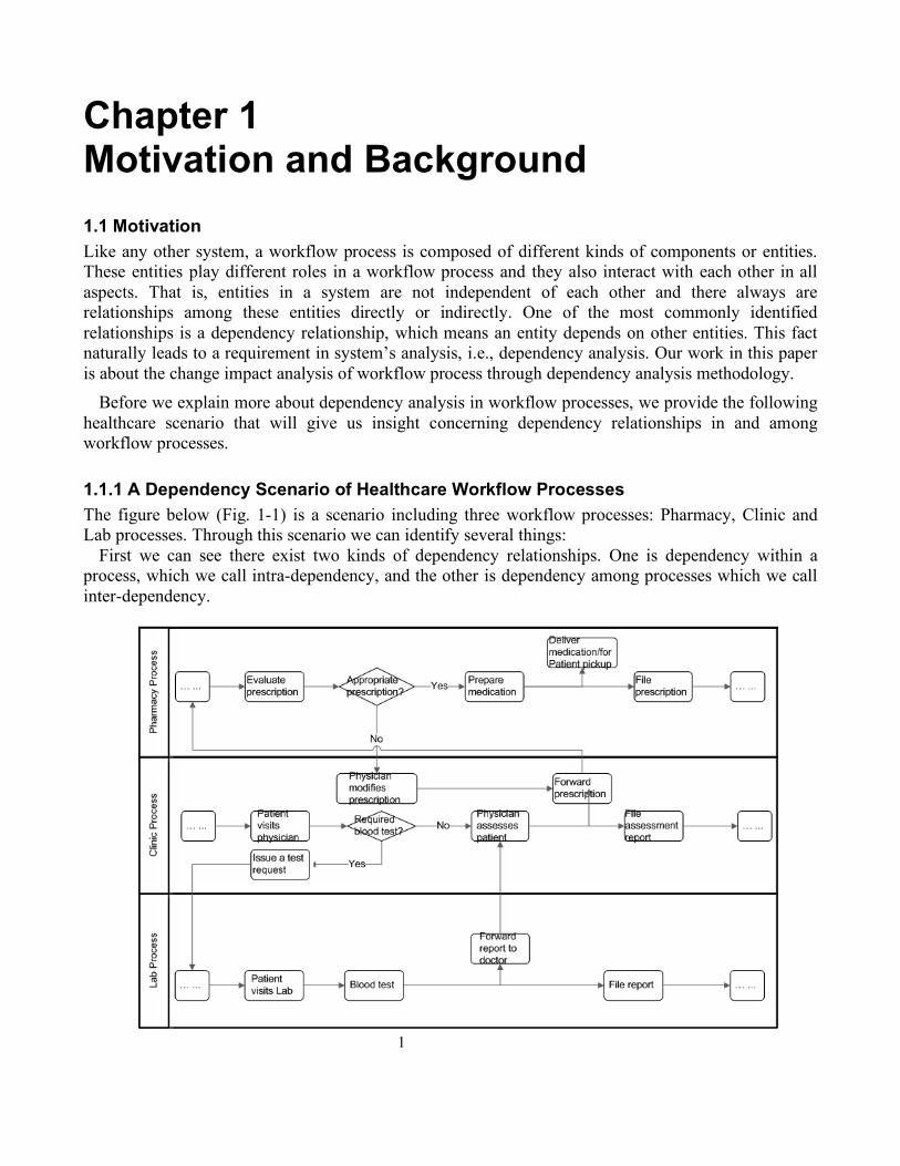
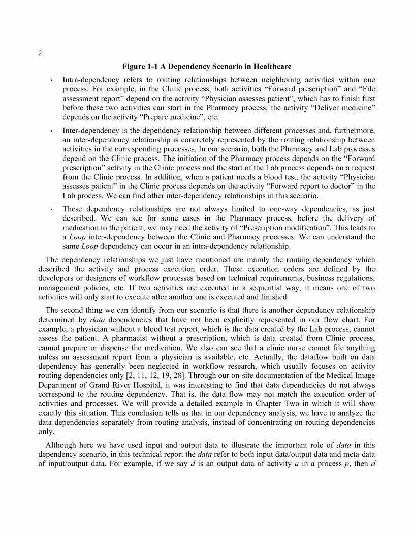
1.1.1 A Dependency Scenario of Healthcare Workflow Processes The figure below (Fig. 1-1) is a scenario including three workflow processes: Pharmacy, Clinic and Lab processes. Through this scenario we can identify several things:
First we can see there exist two kinds of dependency relationships. One is dependency within a process, which we call intra-dependency, and the other is dependency among processes which we call inter-dependency.
2
Figure 1-1 A Dependency Scenario in Healthcare
• Intra-dependency refers to routing relationships between neighboring activities within one process. For example, in the Clinic process, both activities “Forward prescription” and “File assessment report” depend on the activity “Physician assesses patient”, which has to finish first before these two activities can start in the Pharmacy process, the activity “Deliver medicine” depends on the activity “Prepare medicine”, etc.
• Inter-dependency is the dependency relationship between different processes and, furthermore, an inter-dependency relationship is concretely represented by the routing relationship between activities in the corresponding processes. In our scenario, both the Pharmacy and Lab processes depend on the Clinic process. The initiation of the Pharmacy process depends on the “Forward prescription” activity in the Clinic process and the start of the Lab process depends on a request from the Clinic process. In addition, when a patient needs a blood test, the activity “Physician assesses patient” in the Clinic process depends on the activity “Forward report to doctor” in the Lab process. We can find other inter-dependency relationships in this scenario.
• These dependency relationships are not always limited to one-way dependencies, as just described. We can see for some cases in the Pharmacy process, before the delivery of medication to the patient, we may need the activity of “Prescription modification”. This leads to a Loop inter-dependency between the Clinic and Pharmacy processes. We can understand the same Loop dependency can occur in an intra-dependency relationship.
The dependency relationships we just have mentioned are mainly the routing dependency which described the activity and process execution order. These execution orders are defined by the developers or designers of workflow processes based on technical requirements, business regulations, management policies, etc. If two activities are executed in a sequential way, it means one of two activities will only start to execute after another one is executed and finished.
The second thing we can identify from our scenario is that there is another dependency relationship determined by data dependencies that have not been explicitly represented in our flow chart. For example, a physician without a blood test report, which is the data created by the Lab process, cannot assess the patient. A pharmacist without a prescription, which is data created from Clinic process, cannot prepare or dispense the medication. We also can see that a clinic nurse cannot file anything unless an assessment report from a physician is available, etc. Actually, the dataflow built on data dependency has generally been neglected in workflow research, which usually focuses on activity routing dependencies only [2, 11, 12, 19, 28]. Through our on-site documentation of the Medical Image Department of Grand River Hospital, it was interesting to find that data dependencies do not always correspond to the routing dependency. That is, the data flow may not match the execution order of activities and processes. We will provide a detailed example in Chapter Two in which it will show exactly this situation. This conclusion tells us that in our dependency analysis, we have to analyze the data dependencies separately from routing analysis, instead of concentrating on routing dependencies only.
Although here we have used input and output data to illustrate the important role of data in this dependency scenario, in this technical report the data refer to both input data/output data and meta-data of input/output data. For example, if we say d is an output data of activity a in a process p, then d
3
denotes both output data and the meta-data of this output data. Hereafter, we will not include meta-data in our analysis separately. That is, if we say there is a data change, it could be the output data itself changed, e.g., a data element may be unavailable or one output report becomes several output reports; or the meta-data changed, e.g., the role that generated the data is changed, the time when the data is generated is changed, the location where the data is available is changed, etc. The purpose of this definition is to simplify our discussions later and keep our notations concise and consistent. We will discuss data dependency again in the following sections and further in Chapter Two when we analyze our multiple dimension dependency relationships, i.e., routing, data and role dependencies.
1.1.2 Workflow Process Change Background In the real world, there are causes of changes to existing workflow processes. For example, the modification of laws or regulations may require the workflow process to be changed to comply with the new laws or regulations; new medical or healthcare knowledge may require healthcare providers to make corresponding changes in their health service process implementations; new technologies may be introduced into business processes, which replace the jobs previously done by humans to increase efficiency; new systems may be deployed to upgrade old ones in current workflow processes, etc.
As we have discussed, there are many factors that change a process. Usually these factors are of two types, which lead to either intentional change or non-intentional change. Intentional change means the change is purposefully undertaken and its effects expected; while non-intentional change may be caused by human mistakes or unpredictable system errors, e.g., coding bugs, hardware configuration errors, etc. Although we realize that non-intentional change may impact the activities and processes, they are not the point of impact analysis. In this technical report, we will focus on intentional change since its impacts are predicable through our system dependency analysis that will be described in later chapters. Hereafter, when we say change, it means intentional change.
Regarding change, typically it occurs in several stages of a process life cycle: during the design, reengineering/redesign, and maintenance of the process. During the design stage, change is usually driven by the customer requirements, as typical in system and software design domains. However, even with today’s modern design methodologies and tools, we still face challenges in dealing with change.
On the other hand, after a process is designed and is deployed in a specific domain, sometimes because of the significant alteration in customer requirements on the domain environment in which the process is deployed, the process may need reengineering. Process reengineering refers to a systematic approach to modifying or redesigning an existing workflow/business process [23, 46]. The purpose of process reengineering is to achieve improved performance often because of competitive pressures. There are two stages involved in a reengineering procedure: analysis and redesign. Analysis means documenting, dissecting, and assessing an existing process and identifying which activities or processes should be modified, replaced or eliminated, while redesign involves modifying an existing activity or process, or designing a whole new activity or process from scratch, depending on our reengineering objectives.
Finally, the same challenge also occurs in workflow process maintenance. As we mentioned before, a workflow process consists of different entities. In addition to activities, there are other entities within a workflow process, e.g. roles, resources, events, control data, applications, etc. In order to make
4
processes satisfy new expectations and requirements, i.e., efficiency and effectiveness, sometimes a modification to an existing process is required. These changes could happen in many ways, for example, tasks could be supported by upgraded systems, human jobs could be replaced by automated applications, new business or industrial standards could be introduced, traditional data/document media could be changed to electronic media, etc. All of these occur after a (re)designed process is deployed and potentially generate impacts on part of or the whole process.
1.1.3 Motivation Analysis Based on what we have observed and discussed in the previous sections, first we know there exist various dependency relationships among workflow processes, and second there always are changes to processes. These two facts naturally lead to the conclusion that there could be impacts on other activities and processes if we change some activities or processes. For example, if data produced by a preceding activity, say a, are for any reason not available, the activities depending on a cannot be activated. This may lead to the whole process not being executed. Another example can be seen in our previous scenario such as when the lab changes the way a report is made available to a physician, e.g., by uploading it to a webpage instead of forwarding it by mail or fax. In this case the medium that carries the data is changed from paper document to web-based electronic document. Such a change will require the physician to make a corresponding change or modification in his/her process, such as setting up an Internet connection to access the laboratory’s webpage. In this case it is the meta-data of the blood test data that is changed, not the contents of the report, i.e., the data itself. In the future when we say data changes, it means either the input/output data changes and/or the meta-data changes. Here both of these are data dependency examples. However, in Chapter Two we will see there are other kinds of dependency relationships.
Since these changes will continue during the entire process life cycle, an analysis is needed when we handle the impacts of changes at different stages and levels. Moreover, given these examples, and the fact that there often is a complex dependency relationship among workflow processes and activities, we think a workflow Process Impact Analysis (PIA) is an effective way to predict what kinds of impacts we will have. Through PIA, we can identify the affected activities and processes and adapt our process appropriately to satisfy new requirements. In addition to this, new business/workflow processes are being deployed everywhere in order to deliver competitive services to customers or clients. Our objective is to help organizations save effort and time, where the alternative can be business failure. It is for this reason we propose dependency analysis.
1.2 Related Work on Impact Analysis Workflow process research has existed for more than thirty years and is gaining increasing attention from both industry and academy. However, we find that little work has been done on workflow process impact analysis. In [4, 39], the authors have categorized current workflow process research into the following areas: workflow modeling and validation, workflow performance analysis, and process reengineering. Another area of workflow research addresses the design of workflow management systems, which provide runtime environments for workflow execution. Even the dependency relationships within and among workflow process have been identified in [2, 11, 12, 19, 20, 28]. However, these authors focus on workflow modeling or representation, and most of their dependency
5
relationships are limited to process structure dependency, i.e., control or routing dependency. We also notice that these structure dependency relationships are limited to intra-dependency without consideration of inter-dependency, as in our example scenario. We can see the limitation of focus to process structure dependency leads to an incomplete understanding of dependencies. In another paper [29], the author introduces a dependency analysis framework consisting of four separate dependency nets, i.e., activity, role, data and actor. However, the goal of this framework is not to deal with changes to processes and the analysis of their impacts, but rather to generate a set of “transition conditions” that later are deployed in a distributed workflow enactment system, i.e., a management system for process execution.
Although there are few references for workflow impact/dependency analysis, we can take advantage of methodologies and techniques widely applied in software impact analysis, as we can note that a workflow process and a software system share many common characteristics. For example, a software method built on another one is like a complex activity composed of simple ones; interaction between different applications or classes is like interactions among activities or processes; a branch path in code is like parallel control flow, software application deployment and execution is like process deployment and execution, etc. Actually we can treat a workflow process as a variant of a software application. Another interesting similarity between software and a process is the stage at which change occurs. Changes usually occur at the same stages of a process life cycle as they occur during the software life cycle, i.e., design, redesign and maintenance. Furthermore, the reasons for changes in software application are the same as those of workflow processes, and these changes have led to today’s research activities in software impact analysis. From this point of view, we believe that the workflow process impact analysis deserves the same attention in workflow process research as impact analysis in software research.
1.2.1 Software Impact Analysis Software impact analysis is often used to assess the effects of a change on a system after that change has been made. However, a more proactive approach uses impact analysis to predict the effects of change before it is instantiated [9, 10]. In fact, currently the main goal of impact analysis is to identify the software products and entities affected by proposed changes and to produce a list of entities that should be addressed during the proposed change process. As a result, we can evaluate the consequences of planned changes as well as the trade-offs among the approaches to implement the changes. Finally, we decide whether or not to make the changes, or we find other ways to make the changes based on our evaluation.
Most researchers follow the partitions in [10] which classifies impact analysis techniques into two broad categories: dependency analysis and traceability analysis. For dependency analysis, tools are developed to detect and capture dependency information in the system source code artifacts. It includes three subcategories: data, control, and component dependency relationships. Among these relationships, data dependencies are relationships among program statements that define or use data. That is, the data dependence exists when a statement provides a value used by another statement in a program. Control dependencies are relationships among program statements that control program execution, while component dependencies refer to the general relationships among source-code components, e.g., modules, files, etc. Traceability analysis generally is manual work that focuses on
6
modeling dependencies from the perspectives of software-engineering environments and documentation systems that contain varied levels of software information. Examples include requirements traceability that identifies parts of the software that may change with changed requirements, software documentation traceability that identifies the component relationships through the use of a document repository, project information database traceability that provides database-query mechanisms to help software engineers determine the potential impacts of changes based on the project management database, etc. Meanwhile some document management systems have been developed to assist this analysis, e.g., document browsers. Although dependency analysis [1, 15, 22, 31, 38, 43] and traceability analysis [6, 7, 30, 35] can be used separately, they also can be used together to achieve an analysis goal as in [32].
1.2.2 Dependency Analysis and Our Approach As an effective and proven methodology, dependency analysis has been the most mature technique available in impact analysis. The dependency relationships are typically represented as graphs or tables that assist people in understanding the dependencies. Dependencies are stored in a dependency graph in which usually each node represents an entity and each directed edge represents a dependency relationship between entities [10].
On the other hand, we can see that the procedure to identify the affected entities, the types of changes, the effects of a change, etc., is time consuming and costly if handled manually as the analysis domain may be contain many entities and have various dependency relationships at different levels. To deal with this problem, researchers have developed various query or lookup mechanisms that usually are associated with the dependency representation, which provides a foundation for the query. These query mechanisms enable users to select the types of dependencies to be analyzed from the identified dependency relationships and infer the affected entities [1, 10, 15, 22, 42, 43] automatically. There are two advantages of using query mechanisms. First, they make the analysis and identification procedure more efficient than the manual procedure because of the well defined dependency representation. Second, we can realize a more accurate identification as manual identification may lead to some affected entities remaining unidentified because of errors, such as missing some relationships.
As we can see in Figure 1-1, the basic flowchart is a graphical representation of dependency relationships within processes and among processes. We have input/output data associated with activities and the whole process. This is the same as would be associated with software applications. From the perspective of control dependency analysis, we also have the routing entities described in Chapter Two that help to decide the execution paths of process instances based on corresponding decisions. Thus, for our purposes, a dependency analysis focused on data, control and component or entity analysis is a natural choice for our impact analysis of changes in workflow processes. Furthermore, we take the advantage of a query mechanism to automate our analysis procedure. We will discuss this in detail in Chapters Two and Three.
1.3 Contribution Our contribution includes a multi-dimensional workflow process dependency model that includes the critical aspects of dependency relationships existing in workflow processes: routing, data and role dependencies. We then formally represent this model by a logic programming language that is Prolog,
7
through a well-defined knowledge base. Furthermore we develop an effective methodology, the use of query rules, to identify the potentially affected entities in the process analysis domain.
1.4 Technical report Outline In the next chapter, first we give a formal description of a workflow process and its graphical representation. We then show the hierarchical process or subprocess architecture. We further introduce our multi-dimensional workflow dependency model based on a multiple perspective of workflow processes. In Chapter Three, we take the advantage of Prolog to define a knowledge base that represents our dependency model. On the basis of this well-defined knowledge base, we develop a set of query rules that can be applied to querying our multi-dimensional dependency model. In Chapter Four, we apply our knowledge base and query rules through case studies through a Prolog tool XSB [51] which provides a runtime query environment of Prolog. Finally we give our conclusions and discuss future work.
8
Chapter 2 Workflow Dependency Analysis In this chapter, first we give an introduction to workflow processes and their graphic representation, i.e., flowcharts. Second we analyze workflow process dependency relationships based on an activity-based view of processes.
2.1 Background on Workflow Process As a concept and technology, workflow processes, or simply “workflows”, have been developed and deployed in industry, business, government, healthcare and other domains. The evolution of workflow processes from traditional manual processes to today’s technology assisted or automated processes has been underway for a long time. The primary goal of workflow has remained the achievement of effective and efficient ways to provide customers and clients with products or services that satisfy their needs. The benefits of workflow processes can be summarized as reduced cost, improved productivity, better service quality and error control, and improved inter-communication [5].
2.1.1 Workflow Process Definition Although people usually have their own intuitive understanding of workflow, What is Workflow? (Process) is a question people have been trying to answer since this concept was introduced. One of the widely accepted definitions is provided by the Workflow Management Coalition (WfMC) [49]. WfMC is a non-profit international organization primarily engaging developing workflow standards and technologies. It has over 300 members worldwide representing all facets of workflow, from academia to industry, from workflow system vendor to user. It has published a range of documents about workflow representation and implementation. One of the documents is a collection of glossary of all useful terms related to workflow. In the latest version [48], it defines workflow as:
The automation of a business process, in whole or part, during which documents, information or tasks are passed from one participant to another for action, according to a set of procedural rules.
In this definition, WfMC defines a workflow process as the automation of all or part of a business process. So what is a business process and what is the difference between business and workflow processes? Actually, there is much discussion and there exist many views about the answers to these two questions in the academic and industrial worlds. In [3, 27, 39], the authors consider “business process” and “workflow” as synonyms, and the author in [3] sees business process as being a marketing concept. This definition has been proven very successful since workflow vendors are renaming their products to be “business process” products. Some see a business process as a model representation at the abstract and conceptual levels, while they consider a workflow process as a representation at the implementation level with enabling technologies such as workflow management systems (WfMS) [8, 11, 13, 21, 26, 36, 37, 41] that execute business process. We can see that the terms workflow process and business process are used ambiguously.
9
In our work, we follow the definition of WfMC and understand a workflow process as a representation of a business process where all or part of it is supported and executed by automated technologies or systems. At the same time, we consider a workflow process and business process to be the same. In this technical report, we will use workflow process instead of using both in order to make a clear and consistent expression.
We define a workflow process as consisting of a set of entities at different levels, i.e., subprocesses, activities (tasks, steps), roles and control routings, etc., where routing decides the execution order and behavior of activities. An activity is a unit of functionality or unit of service that may be entirely automated or can involve manual interaction with a user or workflow participant to achieve a business goal or objective. Control routings are defined in association with business rules or constraints. A workflow (process) instance or case is executed through the workflow management system with or without interacting with human roles, depending on whether or not there are human roles involved in the workflow process. A workflow management system is a system that defines, creates and manages the execution of workflows through the use of software [48]. Modern workflow processes usually are deployed in a distributed environment. One of the examples is the integration of web services. We will see that this trend may lead to more complex entities in workflow processes and make process analyses a greater challenge.
2.1.2 Control Routing In this section, we introduce the basic routing entities of workflow process defined in the WfMC “Terminology & Glossary” [48]. A routing represents the transition type or control flow between activities. These routing entities are important when we analyze the dependency relationships. Additional term we will use in this technical report are described in Appendix A.
Five control routing types are defined in [48] as follows:
• Sequential: A segment of a process instance in which several activities are executed in sequence under a single thread of execution.
• AND-Split: A point where a single thread of control splits into two or more threads which are executed in parallel, allowing multiple activities to be executed simultaneously.
• AND-Join: A point in the workflow where two or more parallel executing activities converge into a single common thread of control.
• OR-Split: A point where a single thread of control makes a decision upon which branch to take when faced with multiple alternative workflow branches.
• OR-Join: A point where two or more alternative workflow branches re-converge to a single common activity as the next step within the workflow.
To understand the difference between the AND-Join and the OR-Join, the AND-Join requires synchronization while the OR-Join does not require it. Synchronization means the activities that follow can only be executed when all the preceding activities are finished. In this technical report, except for Sequential routing, all other routings are represented as boxes containing the corresponding routing type (Fig. 2-1). Since a Sequential routing is trivial, we usually use only the edge with an arrow to represent it instead of using an explicit entity. In [48], the authors define a special routing
10
“Iteration/Loop” which means a workflow activity cycle involving the repetitive execution of one (or more) workflow activity(ies) until a condition is met. However, it is a routing implemented by the combination of “OR” or “AND” routings. Thus, we do not treat “Iteration/Loop” routing as an independent routing. Among these routings, OR-Split routing is a conditional routing and the activities that follow are selected according to the result of the evaluating of the associated conditions.
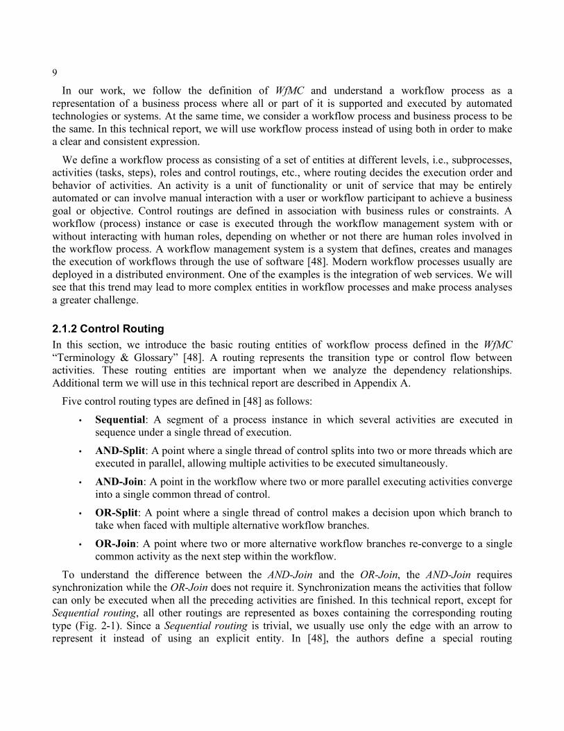
2.1.3 Graphic Representation: Activity Flowchart As we mentioned in dependency analysis, dependency relationships can be represented by a graph. The graphic representation in this technical report is an activity flowchart, which is easy to build and understand. In fact, an activity flowchart is the most often used graphic representation in workflow process research. In an activity flowchart we have two kinds of nodes, one is used to represent activities or (sub)processes; the other is routing entities. Meanwhile, the directed edges show the activity execution order of a process instance determined by the routing entities. Figure 2-1 is a flowchart example with all types of routing entities. Hereafter we will use “flowchart” instead of “activity flowchart”.
In this example and any following workflow process flowcharts, we will use gray boxes to represent activities and (sub)processes while clear boxes represent routings; arrow edges represent the control flow. Figure 2-1 is a simple flowchart example without associated entities. In the following sections, this flowchart construct may be extended when additional entities are introduced.
Figure 2-1 A Flowchart Example
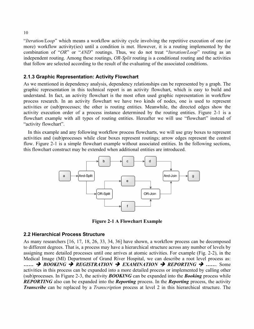
2.2 Hierarchical Process Structure As many researchers [16, 17, 18, 26, 33, 34, 36] have shown, a workflow process can be decomposed to different degrees. That is, a process may have a hierarchical structure across any number of levels by assigning more detailed processes until one arrives at atomic activities. For example (Fig. 2-2), in the Medical Image (MI) Department of Grand River Hospital, we can describe a root level process as: …… BOOKING REGISTRATION EXAMINATION REPORTING ……. Some activities in this process can be expanded into a more detailed process or implemented by calling other (sub)processes. In Figure 2-3, the activity BOOKING can be expanded into the Booking process while REPORTING also can be expanded into the Reporting process. In the Reporting process, the activity Transcribe can be replaced by a Transcription process at level 2 in this hierarchical structure. The
11
same things can be done to other activities in the top level process. However, we don not explicitly show them all.
Figure 2-2 A Hierarchical Structure of Workflow Process in the MI Department Meanwhile a process instance during its execution can call other (sub)processes. In Figure 2-3, we
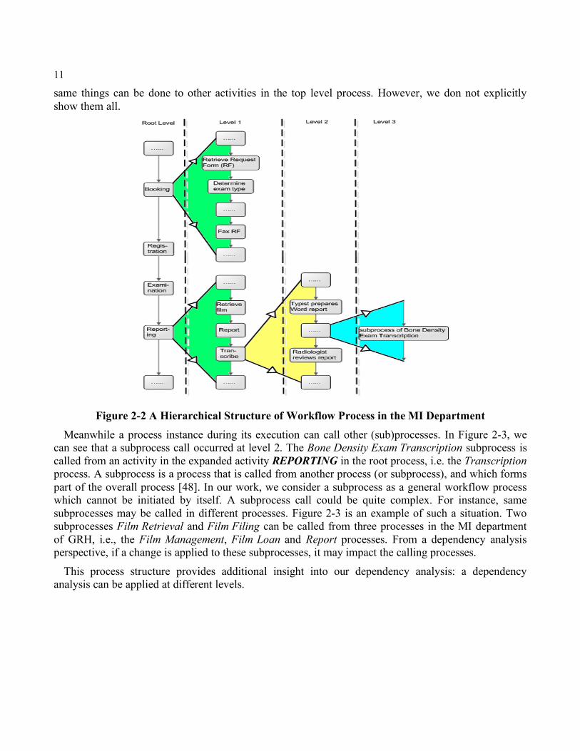
can see that a subprocess call occurred at level 2. The Bone Density Exam Transcription subprocess is called from an activity in the expanded activity REPORTING in the root process, i.e. the Transcription process. A subprocess is a process that is called from another process (or subprocess), and which forms part of the overall process [48]. In our work, we consider a subprocess as a general workflow process which cannot be initiated by itself. A subprocess call could be quite complex. For instance, same subprocesses may be called in different processes. Figure 2-3 is an example of such a situation. Two subprocesses Film Retrieval and Film Filing can be called from three processes in the MI department of GRH, i.e., the Film Management, Film Loan and Report processes. From a dependency analysis perspective, if a change is applied to these subprocesses, it may impact the calling processes.
This process structure provides additional insight into our dependency analysis: a dependency analysis can be applied at different levels.
12
Figure 2-3 A Subprocess Call in the MI Department of GRH
2.3 Workflow Process Dependency Analysis Until now, we have reviewed the related background and knowledge which will be used in our dependency analysis. The most important entities, activity and routing, have been introduced and we can use these entities to build a graphical dependency representation, i.e., an activity flowchart.
Besides activity and routing, depending on the modeling methodologies [19, 26, 27, 28, 34, 36, 45, 48, 50], researchers have identified other entities or elements existing in processes, e.g., role/agent, actor, object, resource, event, rule, goal, exception, organizational unit, enact service, etc. These elements have a common property: they usually cannot exist in a process independently and usually are associated with activities. In workflow process modeling, these elements, under a variety of different names, have been used to represent the workflow processes. We believe that these entities also may have various dependency relationships among them. However, in this technical report we build our dependency analysis model based on a Multiple Perspective Modeling which we describe in detail in the next section.
2.3.1 Multi-Perspective Workflow Process One of the most thorough and detailed modeling views is proposed by Jablonski and Bussler [25], which they call Multiple Perspective Modeling. Actually, many others [28, 36, 47, 40] have used this multi-perspective of workflow process modeling in their workflow process research.
These perspectives are explained below using our own terms:
• Function Perspective, which describes the (recursive) composition of a workflow process out of its subprocesses and activities.
• Operation Perspective, which describes, for each part of the process (subprocesses and activities), which operations it supports and which applications implement these operations.
• Behavior Perspective, which defines the execution order of the workflow process entities (subprocesses and activities).
• Information Perspective, which describes which data is consumed and produced by workflow process and it entities (subprocesses and activities).
13
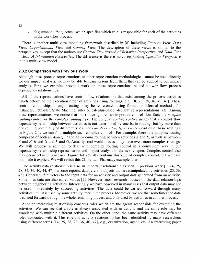
• Organization Perspective, which specifies which role is responsible for each of the activities in the workflow process.
There is another multi-view modeling framework described in [8] including Function View, Data View, Organizational View and Control View. The description of these views is similar to the perspectives, except that the authors use Control View instead of Behavior Perspective, and Data View instead of Information Perspective. The difference is there is no corresponding Operation Perspective in this multi-view model.
2.3.2 Comparison with Previous Work Although these process representations or other representation methodologies cannot be used directly for our impact analysis, we may be able to learn lessons from them that can be applied to our impact analysis. First we examine previous work on these representations related to workflow process dependency relationships.
All of the representations have control flow relationships that exist among the process activities which determine the execution order of activities using routings, e.g., [8, 25, 28, 36, 40, 47]. These control relationships through routings may be represented using formal or informal methods, for instances, Petri-Net, State Machine, rule- or calculus-based, declarative representations, etc. Among these representations, we notice that most have ignored an important control flow fact: the complex routing control or the complex routing type. The complex routing control means that a control flow dependency relationship between activities is not determined by one basic routing, but by more than one routing potentially of different types. The complex routing type is a composition of basic routings. In Figure 2-1, we can find multiple such complex controls. For example, there is a complex routing composed of both an And-Split and an Or-Split routing between activities A and E, as well as between A and F, E and G and F and G. Actually, real world process may have even more complex routings. We will propose a solution to deal with complex routing control in a convenient way in our dependency relationship representation and impact analysis in the next chapter. Complex control also may occur between processes. Figure 1-1 actually contains this kind of complex control, but we have not made it explicit. We will revisit this Clinic-Lab-Pharmacy example later.
The activity data relationship is also an important relationship as seen in previous work [8, 24, 25, 28, 34, 36, 40, 44, 47]. In some reports, data refers to objects that are manipulated by activities [23, 36, 45]. Generally data refers to the input data for an activity and output data generated from an activity. Sometimes data are also called values [2]. However, most research focuses on the data relationships between neighboring activities. Interestingly we have observed in many cases that output data may not be used immediately by succeeding activities. The data could be carried forward through many activities until it is used by some activity later in the process. Moreover, we see that sometimes the data is carried forward through the whole remaining process and only used by activities in another process.
Another interesting relationship concerns roles which are the agents responsible for executing the activities. We can see that a role is always associated with an activity and the same role may be associated with multiple different activities. On the other hand, the same activity may have different roles associated with it. This role and activity relationship has been identified by many researchers using different terms [14, 25, 28, 29, 36, 40, 47], e.g., organization, agent, etc. An interesting paper
14
addresses Agent Assignment [14], i.e., only specific qualified roles can be assigned to or associated with an activity. The reason might be that a business regulation requires a person with certain qualifications to perform a task. This means the change in or replacement of a role is based on whether or not the new role is qualified to perform this activity, i.e., whether or not the new role can carry out the activity with the same features or functionalities as the replaced role. Furthermore, we can imagine that, if an improper change of role in a process occurs, it may lead to unexpected effects on the implementation of the activity or process. The result is either an activity cannot be executed properly with the expected results/output data, or we have to modify the current activities or process to achieve our activity/process objectives. This understanding of the effects of changes in roles is the foundation of our dependency analysis.
We do not include other types of relationships in and among processes in our dependency analysis as separate relationships since they can be understood through other relationships. For example, in the function view/perspective, activity is usually represented in combination with the behavior/control relationship.
As we can see, activity and routing are critical entities in a workflow process and no intra- and inter-process relationships can be built without them. We will next discuss the dependency relationships directly associated with activity and routing and which affect their behaviors.
2.4 Dependency Model for Impact Analysis Based on both the Multiple Perspective Modeling and our analysis of the relationships that are fundamental to our analysis of the impacts of changes in workflow processes, we propose the following multi-dimensional dependency model. It includes three critical dependency relationships: activity routing dependency, data dependency and role dependency. Although we have mentioned other entities and there may exist more dependency relationships, here we focus our analysis on this three-dimensional dependency model other than on every possible dependency relationship. Our purpose is to build an effective and valid model for preliminary impact analysis and thereby establish a solid foundation for future work to include additional dependency relationship analyses.
In this section, we describe thoroughly our dependency model by explaining each dimension of the relationships. The complete formal representation using Prolog will be presented in the following chapter.
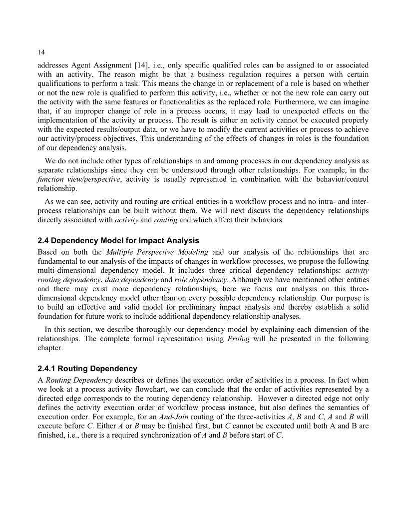
2.4.1 Routing Dependency A Routing Dependency describes or defines the execution order of activities in a process. In fact when we look at a process activity flowchart, we can conclude that the order of activities represented by a directed edge corresponds to the routing dependency relationship. However a directed edge not only defines the activity execution order of workflow process instance, but also defines the semantics of execution order. For example, for an And-Join routing of the three-activities A, B and C, A and B will execute before C. Either A or B may be finished first, but C cannot be executed until both A and B are finished, i.e., there is a required synchronization of A and B before start of C.
15
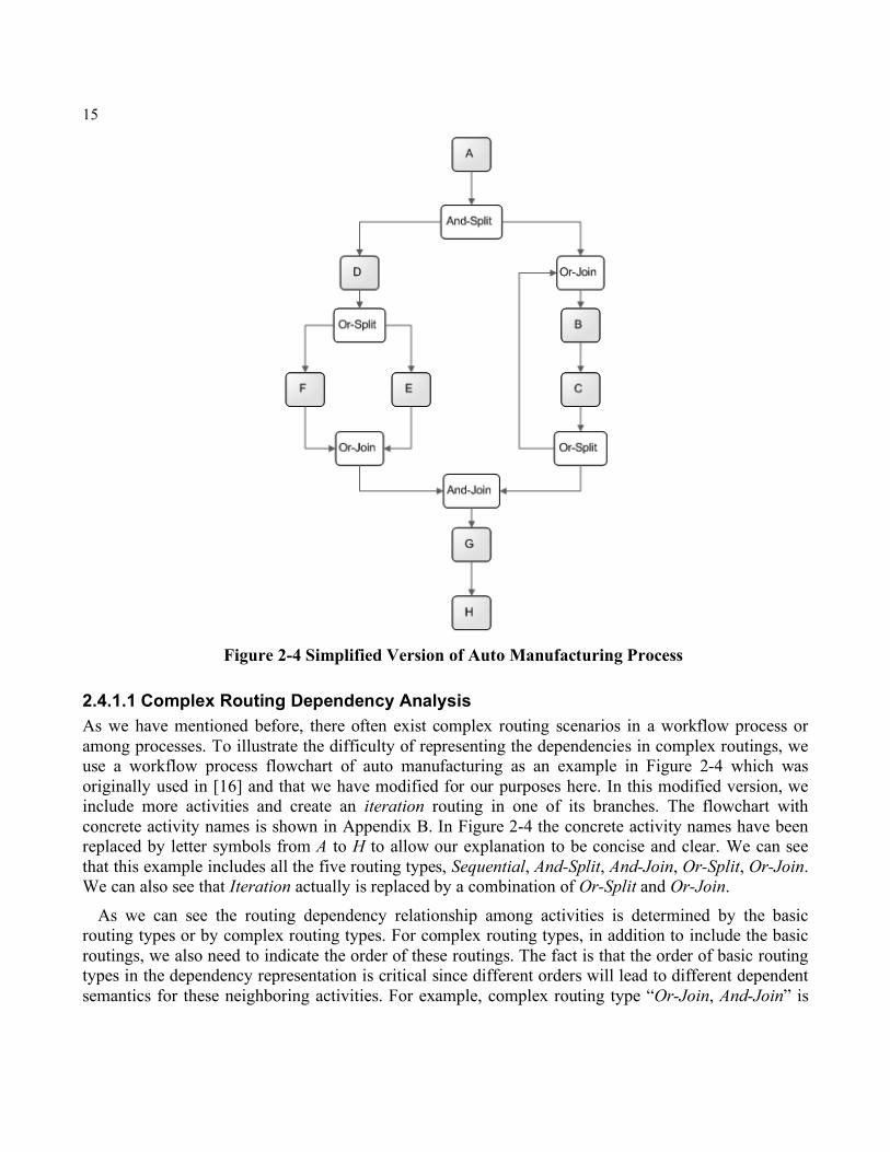
Figure 2-4 Simplified Version of Auto Manufacturing Process
2.4.1.1 Complex Routing Dependency Analysis As we have mentioned before, there often exist complex routing scenarios in a workflow process or among processes. To illustrate the difficulty of representing the dependencies in complex routings, we use a workflow process flowchart of auto manufacturing as an example in Figure 2-4 which was originally used in [16] and that we have modified for our purposes here. In this modified version, we include more activities and create an iteration routing in one of its branches. The flowchart with concrete activity names is shown in Appendix B. In Figure 2-4 the concrete activity names have been replaced by letter symbols from A to H to allow our explanation to be concise and clear. We can see that this example includes all the five routing types, Sequential, And-Split, And-Join, Or-Split, Or-Join. We can also see that Iteration actually is replaced by a combination of Or-Split and Or-Join.
As we can see the routing dependency relationship among activities is determined by the basic routing types or by complex routing types. For complex routing types, in addition to include the basic routings, we also need to indicate the order of these routings. The fact is that the order of basic routing types in the dependency representation is critical since different orders will lead to different dependent semantics for these neighboring activities. For example, complex routing type “Or-Join, And-Join” is
16
different form “And-Join, Or-Join”. In “Or-Join, And-Join” complex type, a synchronization is required just before the succeeding activity’s execution, while in “And-Join, Or-Join” complex type, the synchronization occurs just after the preceding activity’s execution and the succeeding activity does not depend on a synchronization since the “Or-Join” is a non-synchronization routing type. In our example (Fig. 2-4), we can see number of complex types, such as an And-Split followed by an Or-Join, an Or-Join followed by an And-Join, etc. The dependency relationships of neighboring activities, i.e., A B, E G, F G, C B and C G, are determined by more than one basic routing activity. Among them, the dependency between E and G is determined by two routing types: Or-Join and And-Join. Meanwhile, we can see the same routing entities also are shared and used to determine the dependency relationships between other activities, e.g., E G, C G, etc. Although this complex dependency relationship can be understood through a graphic representation, i.e., a flowchart, we can see it leads to a complex and challenging situation when we attempt to describe it formally. This is because a simple combination of multiple routing types cannot give us all of the information related to these routing entities, as we just saw. We are looking for a straightforward dependency representation that enables a clear and unconfused understanding of the complex dependency relationships. We will see in the next chapter that we can take the advantage of Prolog data structure List to represent both the routing combination and order of complex routing types.
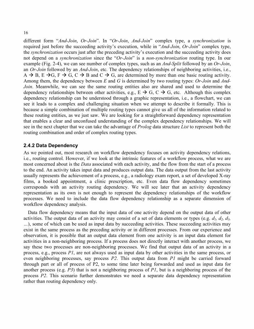
2.4.2 Data Dependency As we pointed out, most research on workflow dependency focuses on activity dependency relations, i.e., routing control. However, if we look at the intrinsic features of a workflow process, what we are most concerned about is the Data associated with each activity, and the flow from the start of a process to the end. An activity takes input data and produces output data. The data output from the last activity usually represents the achievement of a process, e.g., a radiology exam report, a set of developed X-ray films, a booked appointment, a clinic prescription, etc. Even data flow dependency sometimes corresponds with an activity routing dependency. We will see later that an activity dependency representation as its own is not enough to represent the dependency relationships of the workflow processes. We need to include the data flow dependency relationship as a separate dimension of workflow dependency analysis.
Data flow dependency means that the input data of one activity depend on the output data of other activities. The output data of an activity may consist of a set of data elements or types (e.g. d1, d2, d3, …), some of which can be used as input data by succeeding activities. These succeeding activities may exist in the same process as the preceding activity or in different processes. From our experience and observation, it is possible that an output data element from one activity is an input data element for activities in a non-neighboring process. If a process does not directly interact with another process, we say these two processes are non-neighboring processes. We find that output data of an activity in a process, e.g., process P1, are not always used as input data by other activities in the same process, or even neighboring processes, say process P2. This output data from P1 might be carried forward through part or all of process of P2, to some time later being forwarded and used as input data for another process (e.g. P3) that is not a neighboring process of P1, but is a neighboring process of the process P2. This scenario further demonstrates we need a separate data dependency representation rather than routing dependency only.
17
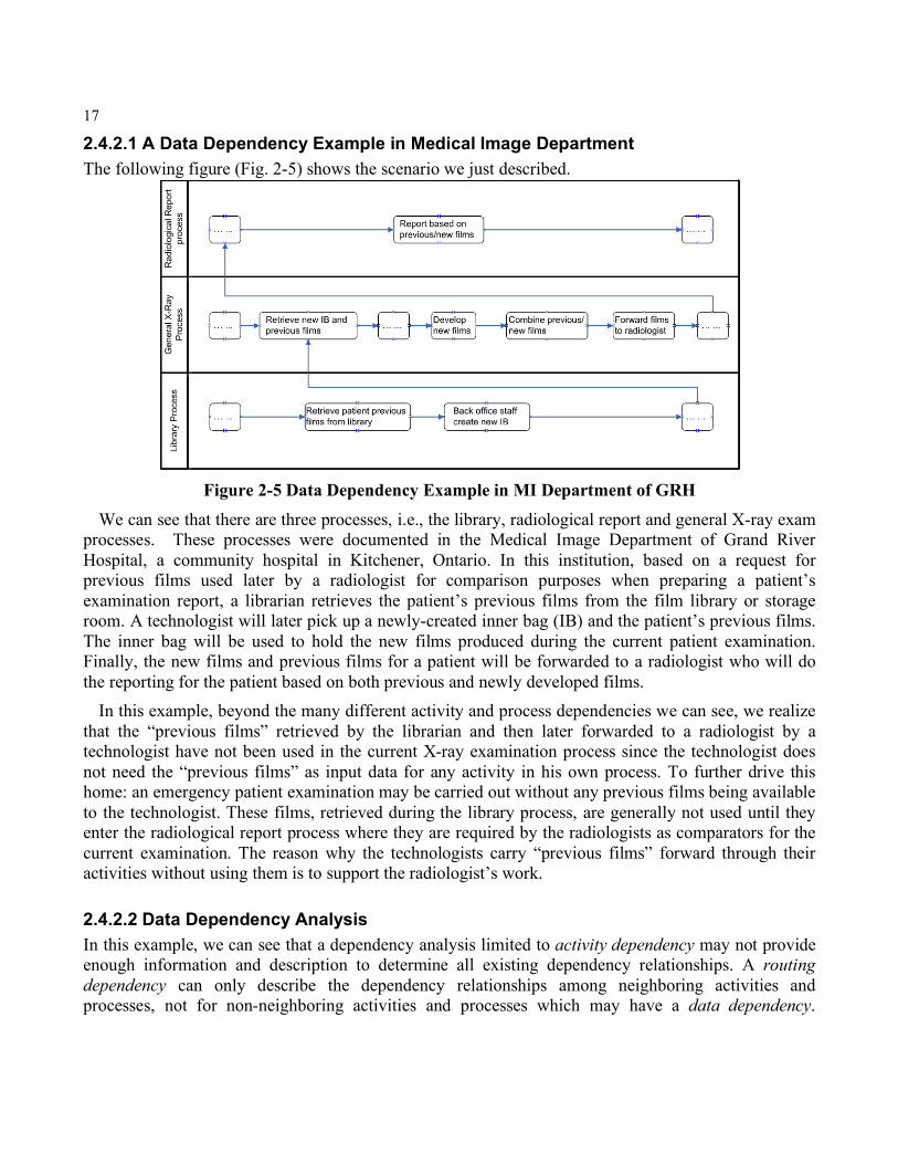
2.4.2.1 A Data Dependency Example in Medical Image Department The following figure (Fig. 2-5) shows the scenario we just described.
Figure 2-5 Data Dependency Example in MI Department of GRH
We can see that there are three processes, i.e., the library, radiological report and general X-ray exam processes. These processes were documented in the Medical Image Department of Grand River Hospital, a community hospital in Kitchener, Ontario. In this institution, based on a request for previous films used later by a radiologist for comparison purposes when preparing a patient’s examination report, a librarian retrieves the patient’s previous films from the film library or storage room. A technologist will later pick up a newly-created inner bag (IB) and the patient’s previous films. The inner bag will be used to hold the new films produced during the current patient examination. Finally, the new films and previous films for a patient will be forwarded to a radiologist who will do the reporting for the patient based on both previous and newly developed films.
In this example, beyond the many different activity and process dependencies we can see, we realize that the “previous films” retrieved by the librarian and then later forwarded to a radiologist by a technologist have not been used in the current X-ray examination process since the technologist does not need the “previous films” as input data for any activity in his own process. To further drive this home: an emergency patient examination may be carried out without any previous films being available to the technologist. These films, retrieved during the library process, are generally not used until they enter the radiological report process where they are required by the radiologists as comparators for the current examination. The reason why the technologists carry “previous films” forward through their activities without using them is to support the radiologist’s work.
2.4.2.2 Data Dependency Analysis In this example, we can see that a dependency analysis limited to activity dependency may not provide enough information and description to determine all existing dependency relationships. A routing dependency can only describe the dependency relationships among neighboring activities and processes, not for non-neighboring activities and processes which may have a data dependency.
18
Therefore we should include a separate data dependency view to supplement our routing dependency for dependency analysis. The activity Reporting in the Radiological Report Process depends not only on the Forward Films to Radiologists activity in the General X-Ray Process, which is a neighboring process to Radiological Report Process, but also on is an activity in the Library Process which is a non-neighboring process to the radiological report process. If we only represent the activity and process dependencies between the Radiological Report and General X-ray processes, we neglect the data dependencies between the Radiological Report and Library processes, an important factor in our impact analysis.
Supposing a PACS (Picture Achieving Communication System) is introduced, we can predict that, within the library process, some activities could be affected since part of the functionality of library process will be replaced by PACS. For example, Retrieve Film, File Film will be affected. However from a data dependency view, the non-neighboring process, the Radiological Report process, is also possibly affected because its input data depend on the Library process. We can see this data dependency between the Library and Radiological Report processes requires the radiologist to find another way to get the “previous films”. The solution is that the radiologist can retrieve this patient’s previous films by accessing the PACS.
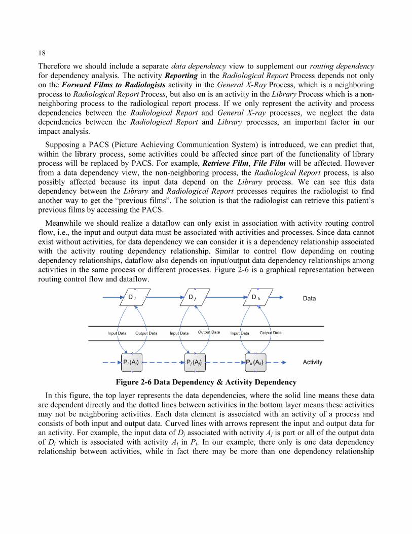
Meanwhile we should realize a dataflow can only exist in association with activity routing control flow, i.e., the input and output data must be associated with activities and processes. Since data cannot exist without activities, for data dependency we can consider it is a dependency relationship associated with the activity routing dependency relationship. Similar to control flow depending on routing dependency relationships, dataflow also depends on input/output data dependency relationships among activities in the same process or different processes. Figure 2-6 is a graphical representation between routing control flow and dataflow.
Figure 2-6 Data Dependency & Activity Dependency
In this figure, the top layer represents the data dependencies, where the solid line means these data are dependent directly and the dotted lines between activities in the bottom layer means these activities may not be neighboring activities. Each data element is associated with an activity of a process and consists of both input and output data. Curved lines with arrows represent the input and output data for an activity. For example, the input data of Dj associated with activity Aj is part or all of the output data of Di which is associated with activity Ai in Pi. In our example, there only is one data dependency relationship between activities, while in fact there may be more than one dependency relationship
19
among multiple data elements, i.e., many to one or one to many. For example, the input data for the activity Aj may come from more than one preceding activity including the activity Ai.
2.4.3 Role Dependency In [29] the author has described the role dependency through a role-net where the implementation of a role-net is achieved by replacing the activity with the role associated with that activity. That is, the activity-based flowchart becomes a role-based flowchart while at the same time the dependency relationships still depend on routing entities. However we will take a different view of role dependency based on the hierarchical structure of organizations and functions rather than using the same flowchart.
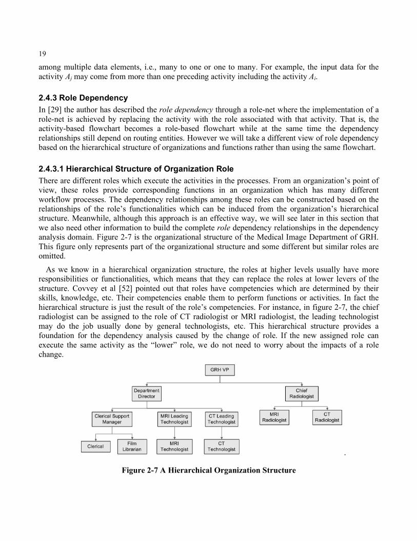
2.4.3.1 Hierarchical Structure of Organization Role There are different roles which execute the activities in the processes. From an organization’s point of view, these roles provide corresponding functions in an organization which has many different workflow processes. The dependency relationships among these roles can be constructed based on the relationships of the role’s functionalities which can be induced from the organization’s hierarchical structure. Meanwhile, although this approach is an effective way, we will see later in this section that we also need other information to build the complete role dependency relationships in the dependency analysis domain. Figure 2-7 is the organizational structure of the Medical Image Department of GRH. This figure only represents part of the organizational structure and some different but similar roles are omitted.
As we know in a hierarchical organization structure, the roles at higher levels usually have more responsibilities or functionalities, which means that they can replace the roles at lower levers of the structure. Covvey et al [52] pointed out that roles have competencies which are determined by their skills, knowledge, etc. Their competencies enable them to perform functions or activities. In fact the hierarchical structure is just the result of the role’s competencies. For instance, in figure 2-7, the chief radiologist can be assigned to the role of CT radiologist or MRI radiologist, the leading technologist may do the job usually done by general technologists, etc. This hierarchical structure provides a foundation for the dependency analysis caused by the change of role. If the new assigned role can execute the same activity as the “lower” role, we do not need to worry about the impacts of a role change.
.
Figure 2-7 A Hierarchical Organization Structure
20
Now we have seen that our role dependency relationships are not based on the flowchart but on the organizational structure. Based on this structure we can identify the relationships among roles. On the other hand, as we previously mentioned, although we are able to utilize the organizational structure to identify the relationships among roles and furthermore to implement our dependency analysis, we also note that in this organizational structure, a role at higher lever may not always be able to implement the functionalities which the role at lower levels usually do. Since the organizational structure is developed by including a management view of roles, i.e. supervision. For example, a MI department director needs to report to the GRH VP because he or she is under the supervision of the VP, but the VP cannot do the job of a department director even that in the figure the VP is at a higher level than the director. To build an appropriate hierarchical role dependency structure, we can start from an organizational structure by combining it with the function view of each role.
2.4.3.2 Dependency Analysis of Role Change The dependency relationships among roles which we have previously described can be explained as follows. If a role, Role A, can be assigned to the same activities that are being executed by another role, Role B, we will say Role B has a dependency relationship on Role A. We can imagine that in some situations, multiple roles, which may be at different higher levels, can be assigned to the activities which are currently executed by another role at a lower level in their hierarchical organizational structure. That is, in role dependency analysis, we may have a one-to-many relationship. In other cases, the same role may be assigned to different activities to replace the current roles, this may lead to the scenario where more than one replacement can occur at different activities of the processes.
Although we can build our role dependency relationships from the organizational and functional hierarchical structures, this kind of dependency still is an activity-based relationship. When we say there is a role dependency, it means this dependency is for a specific activity in a specific process. This exactly corresponds to the fact of role-activity relationship, i.e., a role must be associated with an activity. In next chapter, we will give an example to explain this scenario in detail when we develop our role dependency queries.
In this chapter we have given a clear and complete view of the workflow process and the entities existing in the processes, especially dependency relationships regarding routing, data and role. Meanwhile we also identified some valuable and interesting aspects which have not been identified or clarified in previous research work.
21
Chapter 3 A Logical-Based Dependency Representation and Query In chapter two, we identified and explained our multi-dimensional dependency relationship through a graphical representation. There are three activity-based dependency categories: routing dependency, data dependency and role dependency. In this chapter we first introduce Prolog and its application. We then provide a formal description of workflow process entities and further define a knowledge base using Prolog, which describes our multi-dimensional dependency relationships. Finally, we develop a query mechanism which will be used to retrieve the potential affected entities if changes occur. The defined knowledge base covers the three identified dependency relationships both within process and among processes.
3.1 Prolog Introduction Prolog stands for PROgramming in LOGic which originated in 1970s. The basic idea behind Prolog is that of logic as programming, which sees computation as controlled logical inference. The inference of Prolog is based upon the resolution principle together with mechanisms for extracting answers using linear resolution procedures.
Prolog is a declarative language used to describe problems. It contains facts and rules, where facts state properties which are true of the system we are describing and rules give us a way of deducing new facts from existing ones. A Prolog program is often called a knowledge base because it gives information about a system. This makes a Prolog program different from other programs since we do not “run a program”, instead we query the knowledge base. Given the knowledge base, Prolog will then answer “yes” or “no” to our query. An additional feature of Prolog is that it is a relational program. When we run a query it not only tells us if it is true, but it also lists all the situations which make it true.
Prolog has been widely used in system development and analysis, e.g., expert systems, system simulation, software analysis, etc. In software dependency analysis [1, 10, 15, 22, 42, 43], people usually build a knowledge based model which describes the corresponding dependency relationships among the specified entities, then they define a query or lookup mechanism, e.g., a query manager, query language, impact query rule, etc. The impact analysis is implemented by applying the query mechanism to the knowledge based model. The potentially affected entities are returned or identified through the query. Prolog is a convenient tool to build the Knowledge Base (KB) through defining a set of proper predicates, i.e. facts. A query mechanism can then be developed through existing defined predicates.
3.2 Formal Description of Dependency Entities In this section, we provide a formal definition of dependency entities for workflow processes in the impact analysis domain that we have identified and discussed in previous chapters.
22
The domain to which we will apply our impact analysis consists of a set of processes or subprocesses. In our work, we will treat a subprocess as a special process which is called from or shared by other processes. It is convenient for us to represent a subprocess as a general workflow process in our knowledge base, instead of specifying the subprocesses using a different formalism. Most importantly, this option helps us solve the challenge caused by the need to represent multiple levels of subprocess calling or sharing, e.g., Figure 2-3. We will discuss this again later in the routing query section. In addition to processes in a specific domain, we also have an organizational structure from which we can infer our role dependency relationships through a combination with the role functionality relationship.
As previously mentioned there are many entities that can exist in a process and many potential dependency relationships that can exist among them. In this technical report, we focus on the entities which are directly and internally related to our dependency relationship analysis, i.e., the routing, data and role entities. Among the three entities, the activity is the core entity and other entities are associated with the activity.
The formal description is defined as follows: If M represents the analysis domain and P is the set of processes in M , we can represent the
analysis domain as }{pM = where p is a process in P .
Let E denote the set of entities of process p where p is in P , we have },,,{ RDCAE = where A , C , D and R are four finite sets of entities in process p , A is the set of activities, C is the set of control routings, D is the set of output data associated with activities of p , and R is the set of roles associated with activities of p .
We further define each of A , C , D and R as below:
}{aA = where a represents an activity in process p .
}{cC = where c represents a basic control routing in process p .
)},...,,{(321
aaadddD = where )...( ,2,1 n
ddd denotes the set of output data generated through the execution of activity a in process p .
}{ arR = where r denotes the role assigned to activity a in process p .
In addition to these formal descriptions, we also clarify the following scenario for our knowledge base development. We give the control routing entities in a process unique identifications, even if they are of the same routing type. This is because being of the same type does not indicate they have the same meaning. For instance, routing type Or-Split, depending on the conditions applied to it, will have different semantics for neighboring activities. We give routings in a process their own identifications to differentiate them from one another.
We will use these concepts and definitions in the following section.
23
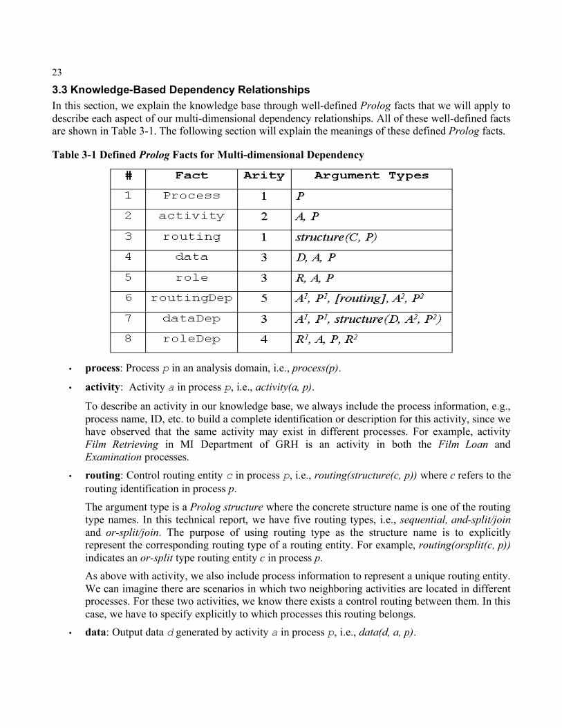
3.3 Knowledge-Based Dependency Relationships In this section, we explain the knowledge base through well-defined Prolog facts that we will apply to describe each aspect of our multi-dimensional dependency relationships. All of these well-defined facts are shown in Table 3-1. The following section will explain the meanings of these defined Prolog facts.
Table 3-1 Defined Prolog Facts for Multi-dimensional Dependency
• process: Process p in an analysis domain, i.e., process(p).
• activity: Activity a in process p, i.e., activity(a, p).
To describe an activity in our knowledge base, we always include the process information, e.g., process name, ID, etc. to build a complete identification or description for this activity, since we have observed that the same activity may exist in different processes. For example, activity Film Retrieving in MI Department of GRH is an activity in both the Film Loan and Examination processes.
• routing: Control routing entity c in process p, i.e., routing(structure(c, p)) where c refers to the routing identification in process p.
The argument type is a Prolog structure where the concrete structure name is one of the routing type names. In this technical report, we have five routing types, i.e., sequential, and-split/join and or-split/join. The purpose of using routing type as the structure name is to explicitly represent the corresponding routing type of a routing entity. For example, routing(orsplit(c, p)) indicates an or-split type routing entity c in process p. As above with activity, we also include process information to represent a unique routing entity. We can imagine there are scenarios in which two neighboring activities are located in different processes. For these two activities, we know there exists a control routing between them. In this case, we have to specify explicitly to which processes this routing belongs.
• data: Output data d generated by activity a in process p, i.e., data(d, a, p).
24
As we often see, multiple data can be generated from one activity. In our defined Prolog fact, one fact denotes one output data. If we have more than one output data, more facts are used to represent these data. For example, if activity a in process p has two output data elements d1 and d2, two facts are required: data(d1, a, p) and data(d2, a, p).
• role: Role r assigned to activity a in process p, i.e., role(r, a, p).
In the real world, for the same activity, it is highly possible that more than one role could be assigned to execute it. For instance, the activity Taking Photo in the process Medical Imaging Examination can be done by roles either Technologist or Radiologist. There are two facts to represent this scenario, i.e., role(Technologist, Taking Photo, Medical Imaging Examination) and role(Radiologist, Taking Photo, Medical Imaging Examination).
• routingDep: Routing dependency relationship between two neighboring activities a1 and a2 in corresponding processes p1 and p2.
In a routing dependency relationship, there are three entities involved: process, activity and routing. Since there may be more than one control routing entity between two neighboring activities, we introduce a prolog list [] to denote these routings. In Prolog, a List represented in [] means an ordered sequence of elements. In our case, the elements refer to basic control routings from pre-activity to post-activity. Meanwhile, we know these basic routings also have to be ordered to express the correct dependency relationship as pointed out in Chapter Two (Section 2.4.1.1). The “ordered” property of List in Prolog exactly matches the “ordered” requirement of routing entities. For example, we can represent the routing dependency between activities a and f in Figure 2-1 as routingDep(a, p, [andsplit(id1, p), orsplit(id2, p)], f, p) where id1 and id2 refer to the identifications of corresponding routing entities and-split and or-split in process p.
• dataDep: Activity a1 in process p1 depends on the output data d from activity a2 in process p2. The structure(D, A2, P2) in fact dataDep is defined as input(d, a2, p2) which indicates the input data d for activity a1 is generated by activity a in process p.
It is evident that one activity may depend on multiple input data, i.e., the output data from preceding activities in the same or other processes. To represent this case, we apply our defined fact dataDep in the same way as fact data. E.g., suppose in process p, if activity c depends on the output data d1 and d2 from activity a and output data d3 from activity b, we can represent these data dependency relationships as dataDep(c, p, input(d1, a, p)), dataDep(c, p, input(d2, a, p)) and dataDep(c, p, input(d3, b, p)). Each fact only represents one input data element.
• roleDep: Role r1 assigned to activity a in process p can be replaced by role r2.
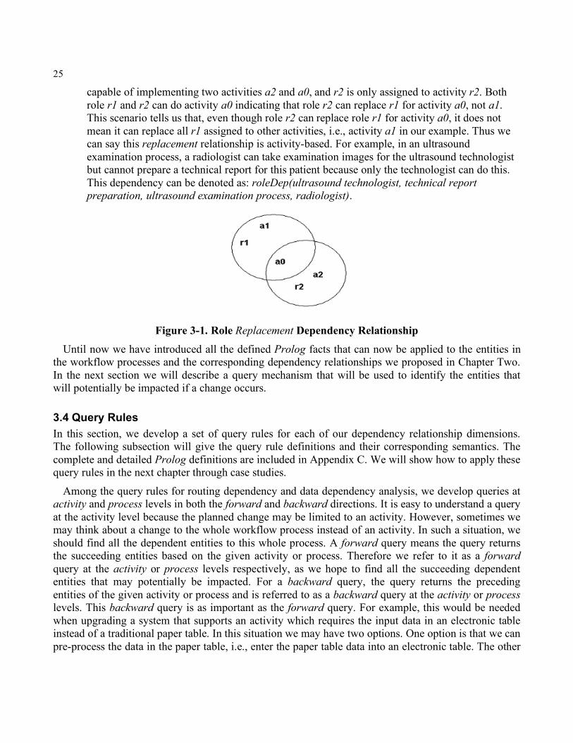
The dependency relationship among roles is a replacement relationship, i.e., one role assigned to an activity can be replaced by another role. Sometimes one role can be replaced by more than one role. Multiple roleDep facts are required to represent this situation. Moreover, we notice this dependency relationship is an activity-based replacement, which means this replacement can only occur related to a specific activity in a specific process. The scenario in Figure 3-1 shows that role r1 can execute and be assigned to two activities a1 and a0. Meanwhile role r2 is
25
capable of implementing two activities a2 and a0, and r2 is only assigned to activity r2. Both role r1 and r2 can do activity a0 indicating that role r2 can replace r1 for activity a0, not a1. This scenario tells us that, even though role r2 can replace role r1 for activity a0, it does not mean it can replace all r1 assigned to other activities, i.e., activity a1 in our example. Thus we can say this replacement relationship is activity-based. For example, in an ultrasound examination process, a radiologist can take examination images for the ultrasound technologist but cannot prepare a technical report for this patient because only the technologist can do this. This dependency can be denoted as: roleDep(ultrasound technologist, technical report preparation, ultrasound examination process, radiologist).
Figure 3-1. Role Replacement Dependency Relationship Until now we have introduced all the defined Prolog facts that can now be applied to the entities in
the workflow processes and the corresponding dependency relationships we proposed in Chapter Two. In the next section we will describe a query mechanism that will be used to identify the entities that will potentially be impacted if a change occurs.
3.4 Query Rules In this section, we develop a set of query rules for each of our dependency relationship dimensions. The following subsection will give the query rule definitions and their corresponding semantics. The complete and detailed Prolog definitions are included in Appendix C. We will show how to apply these query rules in the next chapter through case studies.
Among the query rules for routing dependency and data dependency analysis, we develop queries at activity and process levels in both the forward and backward directions. It is easy to understand a query at the activity level because the planned change may be limited to an activity. However, sometimes we may think about a change to the whole workflow process instead of an activity. In such a situation, we should find all the dependent entities to this whole process. A forward query means the query returns the succeeding entities based on the given activity or process. Therefore we refer to it as a forward query at the activity or process levels respectively, as we hope to find all the succeeding dependent entities that may potentially be impacted. For a backward query, the query returns the preceding entities of the given activity or process and is referred to as a backward query at the activity or process levels. This backward query is as important as the forward query. For example, this would be needed when upgrading a system that supports an activity which requires the input data in an electronic table instead of a traditional paper table. In this situation we may have two options. One option is that we can pre-process the data in the paper table, i.e., enter the paper table data into an electronic table. The other
26
option is to find the preceding activities which generate the paper table to see if they can create an electronic table directly to supply the specific activity’s input data. In such a situation, we can see a backward query is necessary at both activity and process levels.
3.4.1 Routing Dependency Queries A routing dependency relationship represents the execution order relationship of both the activity and process. In fact this order is determined by technical and business requirements as mentioned in Chapter One. When a change occurs to these requirements, the execution order may also require change. If this happens to an activity or a process, we must identify the current routing dependency relationship at both activity and process levels. Based on the results of this identification, we are further able to decide whether the execution orders of activities and processes should be modified to meet the new requirements or not.
Our developed query rules support both forward and backward queries at the activity and process levels respectively. The forward rule queries the succeeding executed activities while the backward rule queries the preceding executed activities. Besides querying the activity routing order, we can also utilize query rules to identify the process execution order and the corresponding activities to which the routing connects, i.e., where this routing dependency relationship exists among the processes. In addition, through a process query, we can identify similar relationships among processes and/or subprocesses. For example, we can determine which processes call a subprocess through a backward process query or which (sub)processes are called from a specified process through a forward process query, etc.
Finally, we define a unique query rule to determine if two given activities are reachable from one to the other. This reachability query is important for impact analysis and has been used in dependency analysis. If the target activity is reachable from the source activity, the target activity then has a direct or indirect routing dependency relationship with the source activity. Otherwise, if a change occurs to the source activity, we do not worry about the potential affect on the target activity since in any case the target activity is not reachable from the source. That is, there is no chance these two activities are executed on the same routing path.
The dependency query rules are included in Table 3-2. The symbols or names in column Type representing arguments or variables refer to different entities and relationships. The variables are required to hold the returned query results in Prolog:
• A and B denote the given activities while P and Q denote the processes in our analysis domain.
• The variable Results refers to the returned results from corresponding query rules.
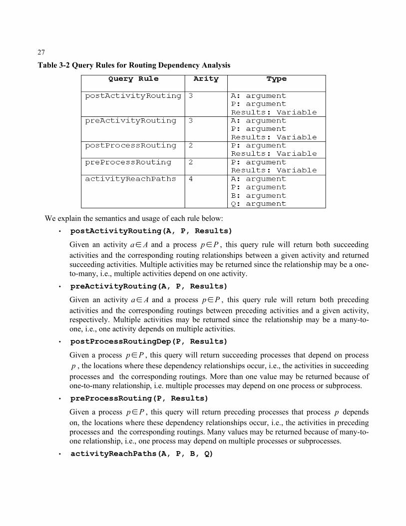
27
Table 3-2 Query Rules for Routing Dependency Analysis
We explain the semantics and usage of each rule below:
• postActivityRouting(A, P, Results)
Given an activity Aa! and a process Pp! , this query rule will return both succeeding activities and the corresponding routing relationships between a given activity and returned succeeding activities. Multiple activities may be returned since the relationship may be a one-to-many, i.e., multiple activities depend on one activity.
• preActivityRouting(A, P, Results)
Given an activity Aa! and a process Pp! , this query rule will return both preceding activities and the corresponding routings between preceding activities and a given activity, respectively. Multiple activities may be returned since the relationship may be a many-to-one, i.e., one activity depends on multiple activities.
• postProcessRoutingDep(P, Results)
Given a process Pp! , this query will return succeeding processes that depend on process p , the locations where these dependency relationships occur, i.e., the activities in succeeding
processes and the corresponding routings. More than one value may be returned because of one-to-many relationship, i.e. multiple processes may depend on one process or subprocess.
• preProcessRouting(P, Results)
Given a process Pp! , this query will return preceding processes that process p depends on, the locations where these dependency relationships occur, i.e., the activities in preceding processes and the corresponding routings. Many values may be returned because of many-to-one relationship, i.e., one process may depend on multiple processes or subprocesses.
• activityReachPaths(A, P, B, Q)
28
Given two activities, source activity Aa! in process Pp! and target activity Ab! in process Pq! . Process p and q may refer to different processes. This query will return a Prolog List or
Nothing where the List indicates it is reachable from source activity (a, p) to target activity (b, q), while Nothing indicates there is no reachability between these two activities. In addition to indicating if they are reachable, the List also contains the paths which start from the source activity and go to the target activity. Each path consists of all of the activities from the source activity to the target activity determined through routing dependency relationships. Multiple paths may be returned since from the start activity we may take different paths to reach the target activity.
The query rules postActivityRouting and postProcessRouting are forward queries at activity and process levels respectively while the rules preActivityRouting and preProcessRouting are backward queries at activity and process levels. Chapter Two described the hierarchical relationships among processes and subprocesses. The postProcessRouting and preProcessRouting query rules will help us identify the dependency relationship existing in this structure.
3.4.2 Data Dependency Queries In previous chapters we showed that data dependency is a critical dimension in our dependency analysis. A change to data has a direct impact on dependent entities. As we have observed that data dependency is not always the same as the dependency relationships of control routing, we develop a separate set of rules to implement our queries.
A data dependency relationship exists because an activity’s input data is the output data of another activity. Since a change to an activity may lead to a change of all of its output data or a specific output data element only, our query rules support both cases. In the former case, all activities depending on any output data will be retrieved. For the latter case we will retrieve only the activities which depend on a specific changed output data element. Meanwhile, similar to routing dependency query rules, we also develop the data dependency query to support both forward and backward queries at the activity and process levels. At the activity level, the forward rule queries the succeeding data-dependent activities, while the backward rule queries the preceding output-data-generating activities. On the other hand, the process level queries will help us identify the data dependency relationship between a given process and other processes. A more detailed description of these queries is given below.
The query rules for data dependency analysis are shown in Table 3-3. As described in the previous section, the symbols or names in column Type representing arguments or variables refer to different entities and relationships. There is a new argument D which denotes the input data or output data depending on the query rules.
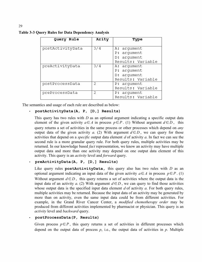
29
Table 3-3 Query Rules for Data Dependency Analysis
The semantics and usage of each rule are described as below:
• postActivityData(A, P, [D,] Results)
This query has two rules with D as an optional argument indicating a specific output data element of the given activity Aa! in process Pp! . (1) Without argument Dd ! , this query returns a set of activities in the same process or other processes which depend on any output data of the given activity a. (2) With argument Dd ! , we can query for those activities that depend on a specific output data element d of activity a. In fact we can see the second rule is a more granular query rule. For both query rules, multiple activities may be returned. In our knowledge based fact representation, we know an activity may have multiple output data and more than one activity may depend on one output data element of this activity. This query is an activity level and forward query.
• preActivityData(A, P, [D,] Results)
Like query rules postActivityData, this query also has two rules with D as an optional argument indicating an input data of the given activity Aa! in process Pp! . (1) Without argument Dd ! , this query returns a set of activities where the output data is the input data of an activity a. (2) With argument Dd ! , we can query to find those activities whose output data is the specified input data element d of activity a. For both query rules, multiple activities may be returned. Because the input data of an activity may be generated by more than on activity, even the same input data could be from different activities. For example, in the Grand River Cancer Center, a modified chemotherapy order may be produced from different activities implemented by pharmacist or physician. This query is an activity level and backward query.
• postProcessData(P, Results)
Given process Pp! , this query returns a set of activities in different processes which depend on the output data of process p, i.e., the output data of activities in p. Multiple
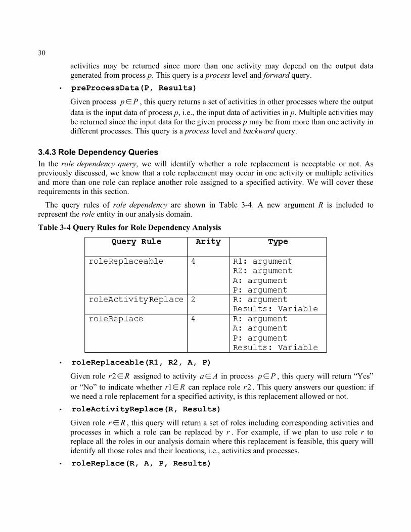
30
activities may be returned since more than one activity may depend on the output data generated from process p. This query is a process level and forward query.
• preProcessData(P, Results)
Given process Pp! , this query returns a set of activities in other processes where the output data is the input data of process p, i.e., the input data of activities in p. Multiple activities may be returned since the input data for the given process p may be from more than one activity in different processes. This query is a process level and backward query.
3.4.3 Role Dependency Queries In the role dependency query, we will identify whether a role replacement is acceptable or not. As previously discussed, we know that a role replacement may occur in one activity or multiple activities and more than one role can replace another role assigned to a specified activity. We will cover these requirements in this section.
The query rules of role dependency are shown in Table 3-4. A new argument R is included to represent the role entity in our analysis domain.
Table 3-4 Query Rules for Role Dependency Analysis
• roleReplaceable(R1, R2, A, P)
Given role Rr !2 assigned to activity Aa! in process Pp! , this query will return “Yes” or “No” to indicate whether Rr !1 can replace role 2r . This query answers our question: if we need a role replacement for a specified activity, is this replacement allowed or not.
• roleActivityReplace(R, Results)
Given role Rr! , this query will return a set of roles including corresponding activities and processes in which a role can be replaced by r . For example, if we plan to use role r to replace all the roles in our analysis domain where this replacement is feasible, this query will identify all those roles and their locations, i.e., activities and processes.
• roleReplace(R, A, P, Results)
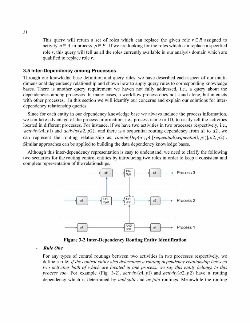
31
This query will return a set of roles which can replace the given role Rr! assigned to activity Aa! in process Pp! . If we are looking for the roles which can replace a specified role r, this query will tell us all the roles currently available in our analysis domain which are qualified to replace role r.
3.5 Inter-Dependency among Processes Through our knowledge base definition and query rules, we have described each aspect of our multi-dimensional dependency relationship and shown how to apply query rules to corresponding knowledge bases. There is another query requirement we haven not fully addressed, i.e., a query about the dependencies among processes. In many cases, a workflow process does not stand alone, but interacts with other processes. In this section we will identify our concerns and explain our solutions for inter-dependency relationship queries.
Since for each entity in our dependency knowledge base we always include the process information, we can take advantage of the process information, i.e., process name or ID, to easily tell the activities located in different processes. For instance, if we have two activities in two processes respectively, i.e.,
)1,1( paactivity and )2,2( paactivity , and there is a sequential routing dependency from 1a to 2a , we can represent the routing relationship as: )2,2)],1,1([,1,1( papsequentialsequentialparoutingDep . Similar approaches can be applied to building the data dependency knowledge bases.
Although this inter-dependency representation is easy to understand, we need to clarify the following two scenarios for the routing control entities by introducing two rules in order to keep a consistent and complete representation of the relationships.
Figure 3-2 Inter-Dependency Routing Entity Identification • Rule One
For any types of control routings between two activities in two processes respectively, we define a rule: if the control entity also determines a routing dependency relationship between two activities both of which are located in one process, we say this entity belongs to this process too. For example (Fig. 3-2), )1,1( paactivity and )2,2( paactivity have a routing dependency which is determined by and-split and or-join routings. Meanwhile the routing
32
dependency relationship between )3,5( paactivity and )2,2( paactivity is composed of or-split and or-join routings. It is noted that this or-join routing is shared by three processes: process 1 (p1), process 2 (p2) and process 3 (p3). We can see that this entity is unnecessary for each process and that it exists because of the inter-dependency relationships among processes as we just described. In such a situation, we need to determine where the location of this routing is, i.e., which process should this routing belong to? After we identify the proper process, we then can represent this routing as a unique entity in our analysis domain. We can see in this example by following Rule 1, there are two activities in the process p2 only, i.e., )2,3( paactivity and )2,2( paactivity , that have a routing dependency relationship containing this or-join routing. So we categorize this or-join entity as a control routing located in the process p2.
• Rule Two Given a routing control that exists as an inter-dependency relationship between two processes, if in either of these two processes there does not exist a pair of activities which have an intra-dependency relationship determined by this routing control, we say that this routing entity belongs to the source process, i.e., this routing entity is in the same process as the pre-activity.
The application of a query rule to an inter-dependency in our knowledge base is the same as with intra-dependency. Furthermore, since we include process information in our entity and dependency representations, the returned values will tell us exactly in which processes these entities are located. This is the reason why at the beginning we defined the Prolog facts and rules by including the process information.
In Chapter Three, we successfully built a knowledge base through a logic programming
representation language using Prolog. We then developed a set of the query rules which we will see in next chapter is an effective mechanism for dependency analysis.

33
Chapter 4 A Healthcare Case Study In this chapter, we introduce a case involving healthcare workflow processes and show how to apply our approach to describe the previously identified multiple dependency relationships. Furthermore we also show the application of our query rules at different levels to identify the entities potentially affected by a change. As intra-dependency and inter-dependency usually occur at the same time in an analysis domain, we will apply these dependency analyses to a case which contains multiple workflow processes.
4.1 Case Implementation Tool and Environment To implement our case studies, we use a Prolog tool XSB. XSB is a research-oriented, commercial-grade Logic Programming system for Unix and Windows-based platforms. It is an extension of the typical Prolog system, introducing additional logic evaluation features beyond Prolog. Meanwhile it also provides a runtime query environment for Prolog. For the purpose of our case study, we choose to implement our dependency analysis queries on a windows-based platform, i.e., Windows 2000 Professional, and start XSB from the DOS command line.
Our knowledge bases for the dependency relationships are stored as files whose names have the suffix .p as required by XSB. After building the process dependency knowledge base for our case, both the knowledge base and our defined query rules are compiled and processed in XSB. We then can do the dependency analysis through applying our query rules to the knowledge base.
4.2 Case Study Analysis Domain and Description For our research purposes, we have documented the current workflow processes of Grand River Region Cancer Center (GRRCC). Our case study will involve these processes related to outpatient chemotherapy. Hereafter, we will use the term patient instead of outpatient. There are four workflow processes in our case study: Patient Clinic Process (PC), Pharmacist Process (PH), Patient Chemotherapy Process (PCH) and Chemo Technician (Sub)process (CT). Among these processes, the Chemo Technician Process is a subprocess since both the outpatient and inpatient chemotherapy processes use it and share it in their respective processes.
Figure 4-1 shows the detailed activities in each process and the relationships among the activities and processes. In fact, these processes are the simplified versions of the actual healthcare processes. The reason is that the actual processes are very detailed, which would make our case study unnecessarily complex and difficult to understand. On the other hand, although they are the simplified processes, we still retain the critical activities and routings, and we are also able to show typical dependency relationships among them.
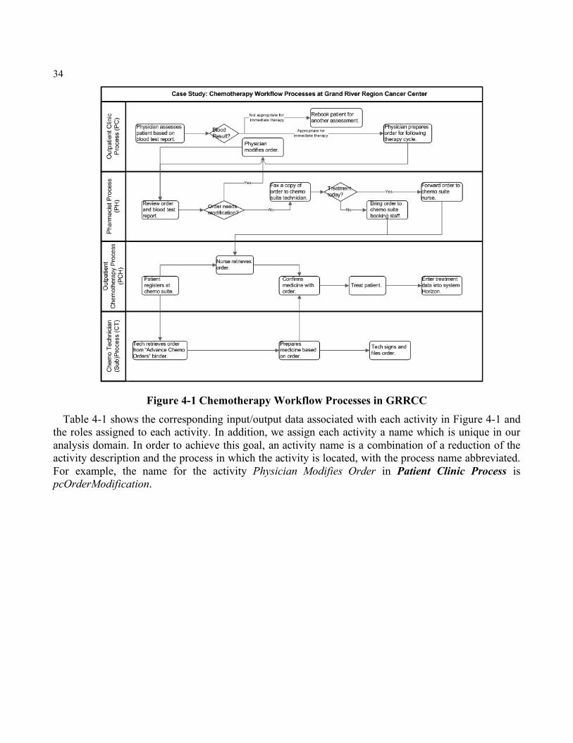
34
Figure 4-1 Chemotherapy Workflow Processes in GRRCC Table 4-1 shows the corresponding input/output data associated with each activity in Figure 4-1 and
the roles assigned to each activity. In addition, we assign each activity a name which is unique in our analysis domain. In order to achieve this goal, an activity name is a combination of a reduction of the activity description and the process in which the activity is located, with the process name abbreviated. For example, the name for the activity Physician Modifies Order in Patient Clinic Process is pcOrderModification.
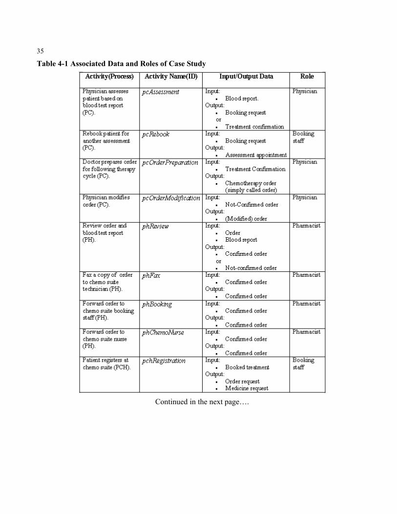
35
Table 4-1 Associated Data and Roles of Case Study
Continued in the next page….
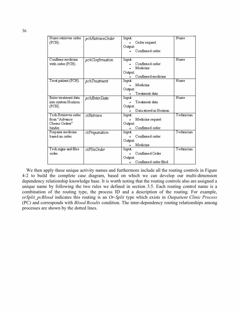
36
We then apply these unique activity names and furthermore include all the routing controls in Figure
4-2 to build the complete case diagram, based on which we can develop our multi-dimension dependency relationship knowledge base. It is worth noting that the routing controls also are assigned a unique name by following the two rules we defined in section 3.5. Each routing control name is a combination of the routing type, the process ID and a description of the routing. For example, orSplit_pcBlood indicates this routing is an Or-Split type which exists in Outpatient Clinic Process (PC) and corresponds with Blood Results condition. The inter-dependency routing relationships among processes are shown by the dotted lines.
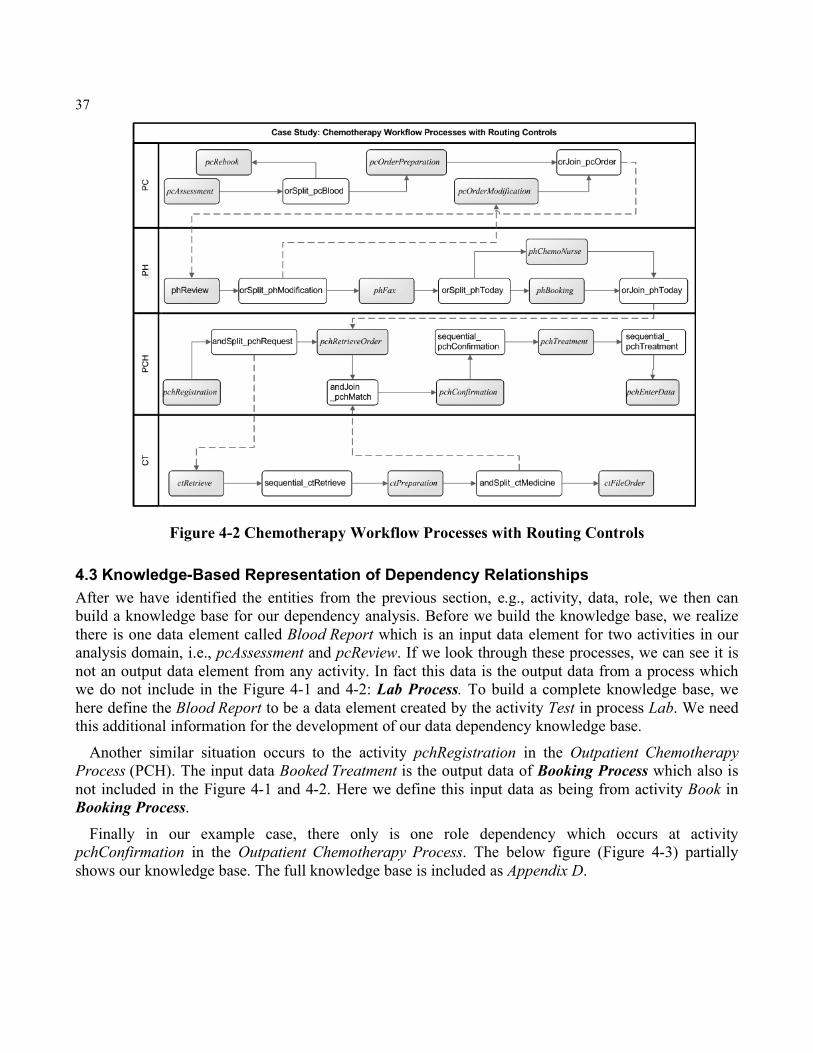
37
Figure 4-2 Chemotherapy Workflow Processes with Routing Controls
4.3 Knowledge-Based Representation of Dependency Relationships After we have identified the entities from the previous section, e.g., activity, data, role, we then can build a knowledge base for our dependency analysis. Before we build the knowledge base, we realize there is one data element called Blood Report which is an input data element for two activities in our analysis domain, i.e., pcAssessment and pcReview. If we look through these processes, we can see it is not an output data element from any activity. In fact this data is the output data from a process which we do not include in the Figure 4-1 and 4-2: Lab Process. To build a complete knowledge base, we here define the Blood Report to be a data element created by the activity Test in process Lab. We need this additional information for the development of our data dependency knowledge base.
Another similar situation occurs to the activity pchRegistration in the Outpatient Chemotherapy Process (PCH). The input data Booked Treatment is the output data of Booking Process which also is not included in the Figure 4-1 and 4-2. Here we define this input data as being from activity Book in Booking Process.
Finally in our example case, there only is one role dependency which occurs at activity pchConfirmation in the Outpatient Chemotherapy Process. The below figure (Figure 4-3) partially shows our knowledge base. The full knowledge base is included as Appendix D.

38
Figure 4-3 Partial Representation of Knowledge Base
4.4 Workflow Process Dependency Analysis In this section, we will apply our query rules to the well-defined knowledge-based dependency model we described in previous sections. The dependency analysis cases will cover all relevant dimensions: routing, data and role. It is noted that we have defined many query rules for various dependency analysis purposes. However in this section we do not apply all of these rules but rather only apply rules that are relevant to typical cases in healthcare.
Table 4-2 is the summary of our analysis of cases. For each case, we specify the corresponding category and the query motivation upon the given entities and the applied query rule. Figure 4-4, 4-5 and 4-6 show the query executions of the analysis cases for routing, data and role dependency analysis respectively. These query executions are in the same order as the cases in Table 4-2.
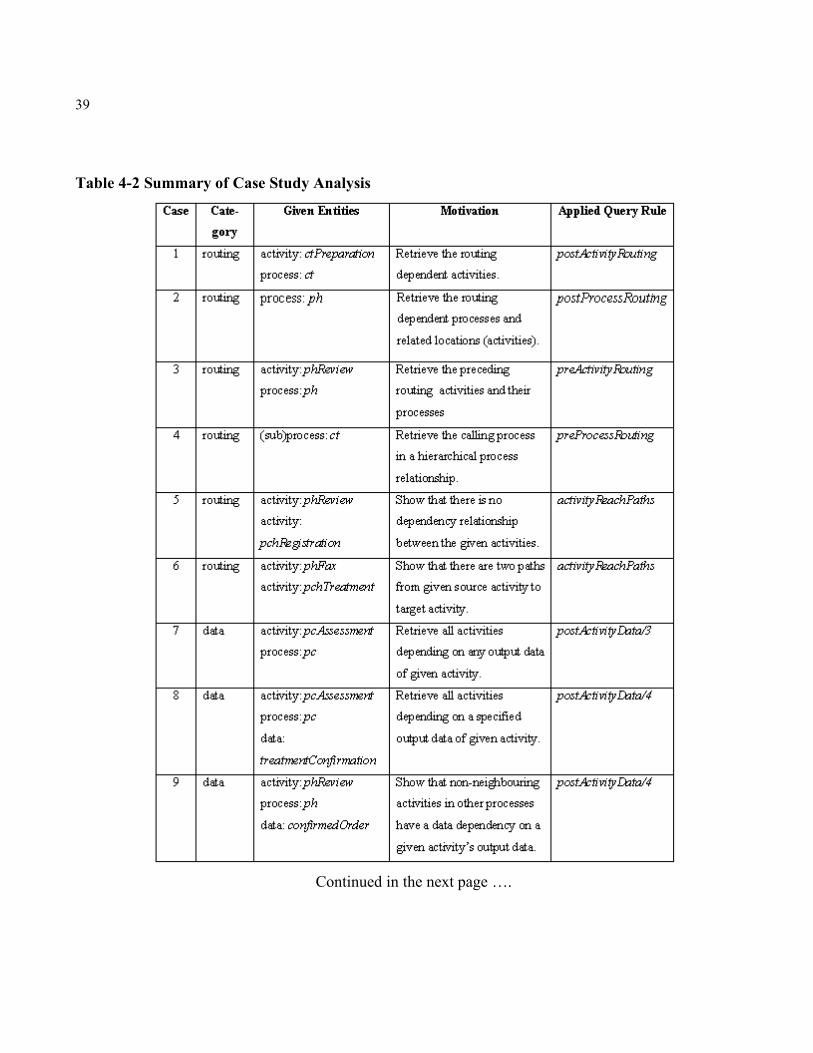
39
Table 4-2 Summary of Case Study Analysis
Continued in the next page ….
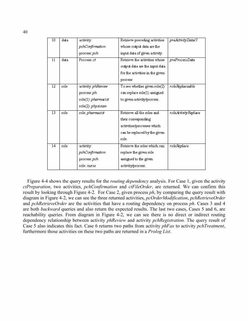
40
Figure 4-4 shows the query results for the routing dependency analysis. For Case 1, given the activity ctPreparation, two activities, pchConfirmation and ctFileOrder, are returned. We can confirm this result by looking through Figure 4-2. For Case 2, given process ph, by comparing the query result with diagram in Figure 4-2, we can see the three returned activities, pcOrderModification, pchRetrieveOrder and pchRetrieveOrder are the activities that have a routing dependency on process ph. Cases 3 and 4 are both backward queries and also return the expected results. The last two cases, Cases 5 and 6, are reachability queries. From diagram in Figure 4-2, we can see there is no direct or indirect routing dependency relationship between activity phReview and activity pchRegistration. The query result of Case 5 also indicates this fact. Case 6 returns two paths from activity phFax to activity pchTreatment, furthermore those activities on these two paths are returned in a Prolog List.
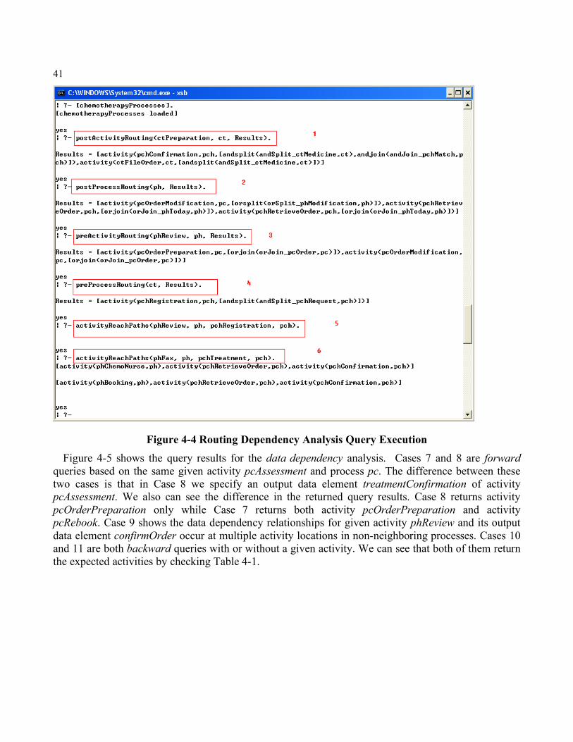
41
Figure 4-4 Routing Dependency Analysis Query Execution Figure 4-5 shows the query results for the data dependency analysis. Cases 7 and 8 are forward
queries based on the same given activity pcAssessment and process pc. The difference between these two cases is that in Case 8 we specify an output data element treatmentConfirmation of activity pcAssessment. We also can see the difference in the returned query results. Case 8 returns activity pcOrderPreparation only while Case 7 returns both activity pcOrderPreparation and activity pcRebook. Case 9 shows the data dependency relationships for given activity phReview and its output data element confirmOrder occur at multiple activity locations in non-neighboring processes. Cases 10 and 11 are both backward queries with or without a given activity. We can see that both of them return the expected activities by checking Table 4-1.
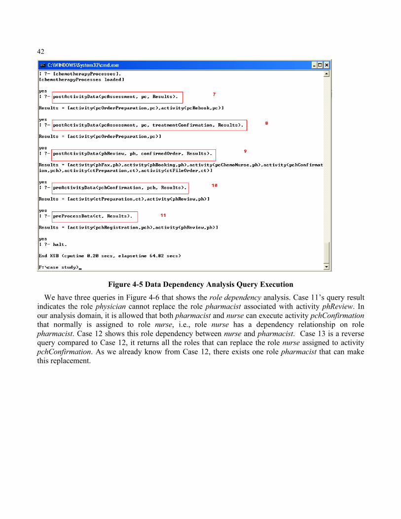
42
Figure 4-5 Data Dependency Analysis Query Execution We have three queries in Figure 4-6 that shows the role dependency analysis. Case 11’s query result
indicates the role physician cannot replace the role pharmacist associated with activity phReview. In our analysis domain, it is allowed that both pharmacist and nurse can execute activity pchConfirmation that normally is assigned to role nurse, i.e., role nurse has a dependency relationship on role pharmacist. Case 12 shows this role dependency between nurse and pharmacist. Case 13 is a reverse query compared to Case 12, it returns all the roles that can replace the role nurse assigned to activity pchConfirmation. As we already know from Case 12, there exists one role pharmacist that can make this replacement.
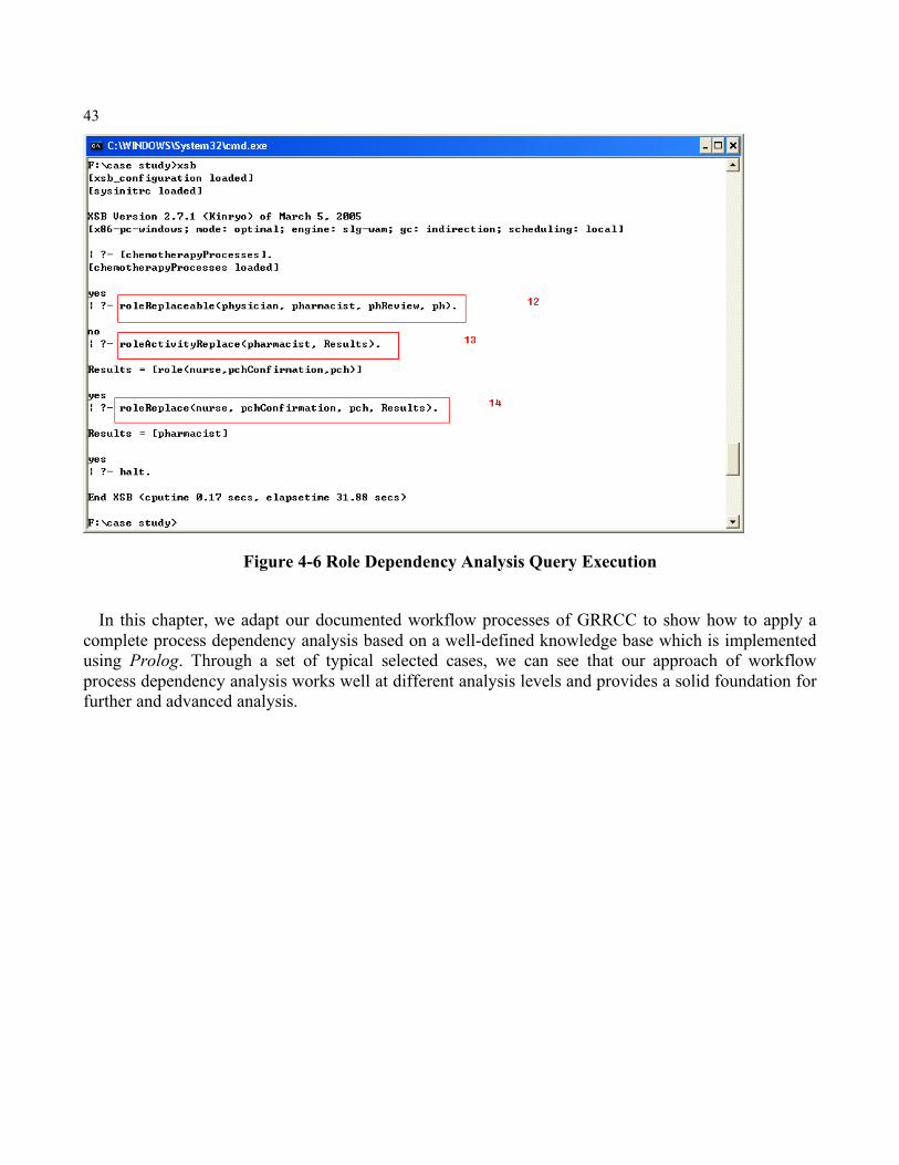
43
Figure 4-6 Role Dependency Analysis Query Execution In this chapter, we adapt our documented workflow processes of GRRCC to show how to apply a
complete process dependency analysis based on a well-defined knowledge base which is implemented using Prolog. Through a set of typical selected cases, we can see that our approach of workflow process dependency analysis works well at different analysis levels and provides a solid foundation for further and advanced analysis.
44
Chapter 5 Conclusion and Future Work Although it is widely known that impact analysis is a very important research topic in systems analysis, we have not seen much attention to impact analysis related to workflow process research. Like in any other type of system, changes in workflow processes are unavoidable and these changes occur at all stages of the process life cycle. The purpose of impact analysis is to reduce the “ripple effect” where making a small change to a system affects many other parts or entities of the system. This is done through identifying and tracing the dependency relationships between the changed part and other potentially affected parts.
This technical report contributes to the area of workflow process impact analysis by analyzing and representing the dependency relationships among the process entities. We have proposed a multi-dimensional view of workflow process dependency relationships: routing dependency, data dependency and role dependency. We have then defined a set of atomic predicates in Prolog and, based on these well-defined predicates, we have constructed a knowledge base for each dimension of our dependency relationships. Finally, we have developed an effective query mechanism, i.e., query rules in Prolog, which can be applied to the knowledge bases to identify the potentially affected entities, given a specific change. In addition, a case study involving multiple healthcare workflow processes has been given to show how our analysis works. This has included the development of a dependency relationship knowledge base and the application of query rules.
Although we have achieved our goals in this technical report, we realize there are many other challenges existing in workflow process impact analysis that are worthy of further attention in future research. We discuss them here.
First, in this technical report we focused on the limited entities: activity, role, routing and data only. In section 2.3, in fact we mentioned a number of other entities related to workflow processes. These entities, e.g., goal, rule, resource, event, exception, etc. also have dependency relationships among themselves and those already identified, i.e., activity, role and data. We can see that a further identification and classification of these dependency relationships and their incorporation into a comprehensive impact analysis will be necessary.
Second, our dependency knowledge is generated based on a graphic representation, i.e., flowcharts that implicitly and explicitly contain these dependency relationships. While we can see that flowcharts are very helpful in identifying these relationships, flowcharts are an inconvenient formalism from which to generate these dependency representations automatically. A better choice would be a declarative representation of workflow processes from which we could directly and automatically identify and generate these dependency relationships.
Third, although we take advantage of software impact analysis, the workflow processes are different from a general software application. In most of the cases, a workflow process instance is executed by a combination of humans and systems. This mixture of manual and automatic agents adds more entities into the design and implementation of a process. Meanwhile, we realize a workflow process usually is
45
deployed in a distributed environment which makes dependency relationships more complicated and harder to analyze. This also makes the dependency analysis more challenging.
Fourth, the building of the dependency relationship among roles is quite complex since the functionalities of a role are not only determined by what this role can do, but also by what this role is allowed to do. Especially since a real workflow process is usually deployed in a distributed networking environment, authentication and authorization are “a must”. When we think about the replacement relationship of roles, at the same time we also have to think about their authentication and authorization. In this technical report we developed our role dependency relationship primarily from the single hierarchical organizational structure. In the future, we will need to generate the role replacement relationships using a more comprehensive and formal representation of the role functionalities.
There are other dependency relationships. One of them is the routing condition whose evaluation depends on other entities, e.g., data, role, etc. In this technical report we have limited the routing conditions to Or-Split routing only. However, in the real world a condition may be associated with other routing controls. For example, a sequential routing may have a temporal condition, i.e., a time condition to indicate that the post-activity can only start after some period of time. In addition, this kind of conditional dependency relationship with other entities could be very versatile. In our documented workflow processes of the Cancer Center at GRH, a condition could be the distance of the patient’s location form the Center, the execution time of an activity, etc. We think this dependency could be a valuable aspect of workflow process impact analysis.
As we have pointed out, there has not been enough attention and research focused on workflow process impact analysis, although the workflow process research and commercial development are attracting more people from both the academic and industrial fields. Our work is a preliminary view and an early initiative in process impact analysis. We have described some unsolved and interesting questions and challenges related to process dependency analysis, and we definitely have not addressed every aspect of this topic. We look to the future for more systematic analyses and more complete dependency relationship representation as these are essential for the advancement of this field.
46
Appendix A Workflow Process Terminology
The following terminologies are excerpted from [48].
• Workflow The automation of a business process, in whole or part, during which documents, information or tasks are passed from one participant to another for action, according to a set of procedural rules.
• Workflow Management System A system that defines, creates and manages the execution of workflows through the use of software.
• Business Process A set of one or more linked procedures or activities which collectively realize a business objective, normally within the context of an organizational structure defining functional roles and relationships.
• Process Definition The process definition consists of a network of activities and their relationships, criteria to indicate the start and termination of the process, and information about the individual activities, such as participants, associated IT applications and data, etc.
• Activity A description of a piece of work that forms one logical step within a process. There are two kinds of activities, manual and automated.
• Instance (Process Instance or Activity Instance) The representation of a single enactment of a process, or activity within a process, including its associated data.
• Workflow Participant (Role) A resource that performs the work represented by a workflow activity instance.
• Subprocess A process that is enacted or called from another (initiating) process (or subprocess), and which forms part of the overall (initiating) process. In our work, we treat a subprocess as a general workflow process.
• Event An occurrence of a particular condition that causes the workflow management software to take one or more actions. An event has two elements: trigger and action.
• Constraint (Rule) A condition that must be met during work processing; failure to meet a constraint may causes an exception condition or other defined procedure.
• Workflow Engine A software service or "engine" that provides the run time execution environment for a process instance.
• Parallel Routing A segment of a process instance where two or more activity instances are executing in parallel within the workflow, giving rise to multiple threads of control.
• Iteration/Loop A workflow activity cycle involving the repetitive execution of one (or more) workflow activity(s) until a condition is met.
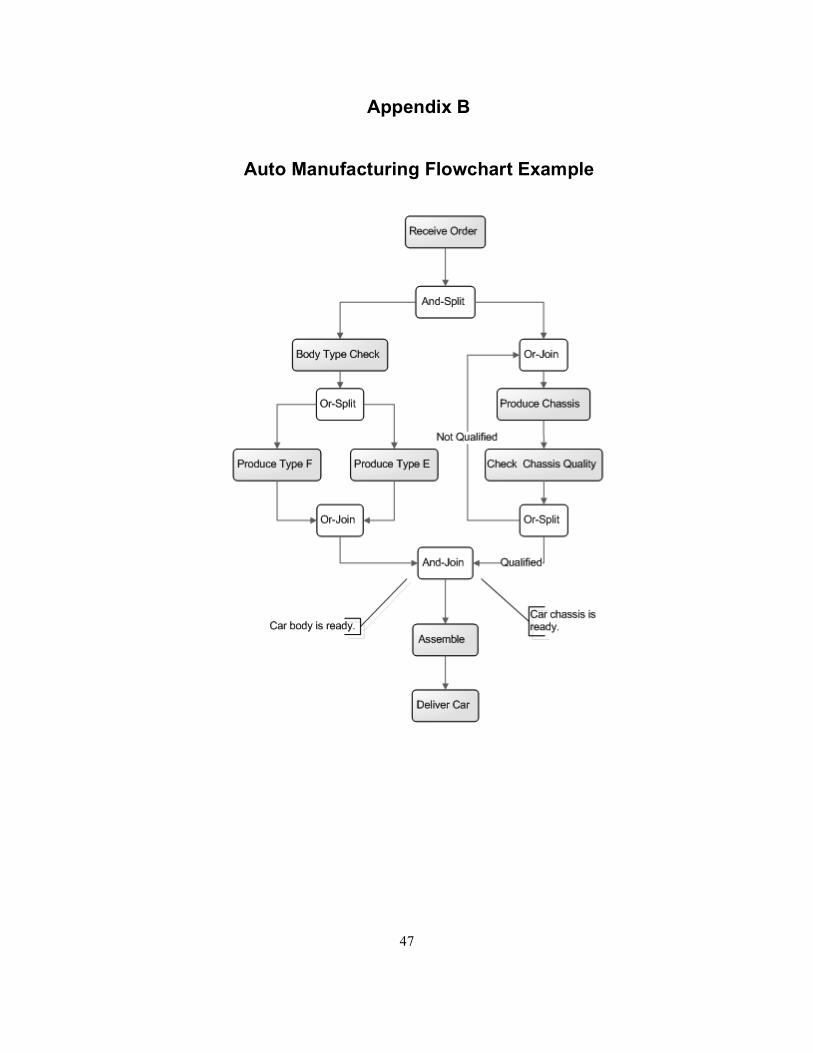
47
Appendix B
Auto Manufacturing Flowchart Example
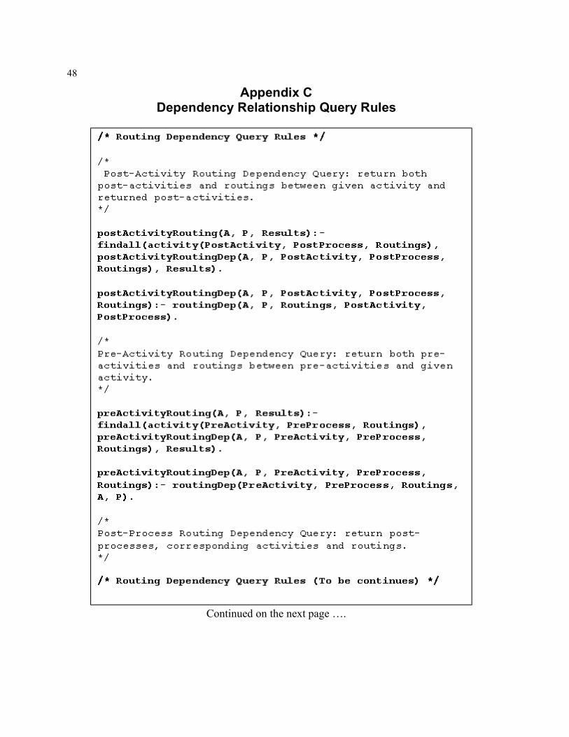
48
Appendix C Dependency Relationship Query Rules
Continued on the next page ….
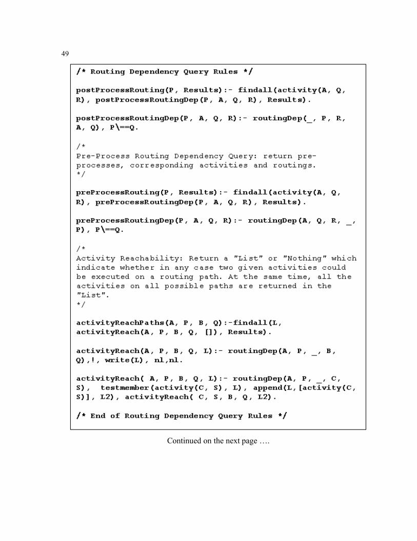
49
Continued on the next page ….
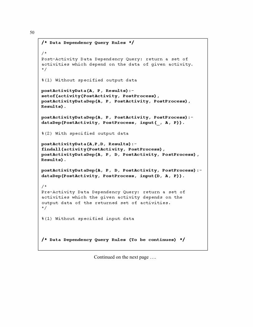
50
Continued on the next page ….
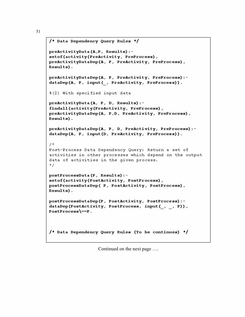
51
Continued on the next page ….
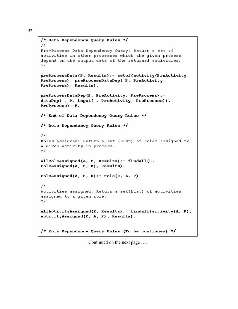
52
Continued on the next page ….
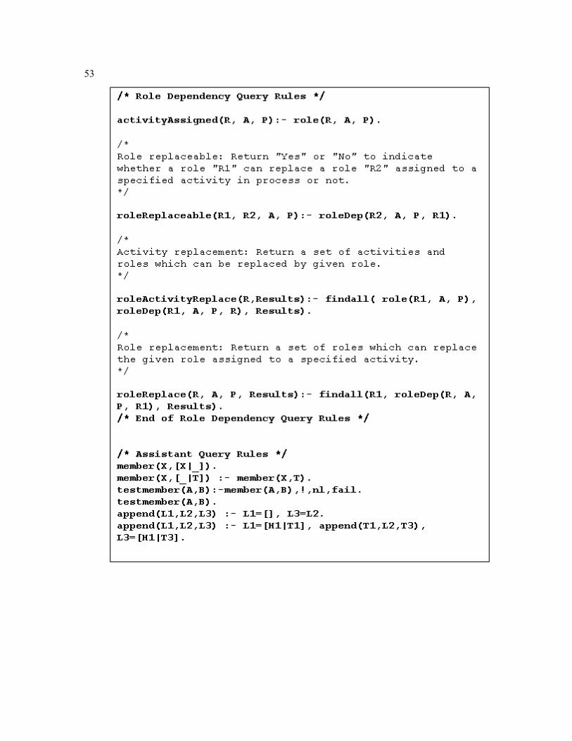
53
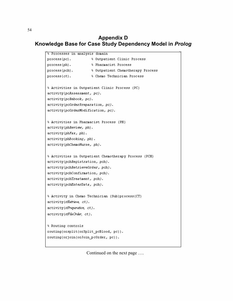
54
Appendix D Knowledge Base for Case Study Dependency Model in Prolog
Continued on the next page ….
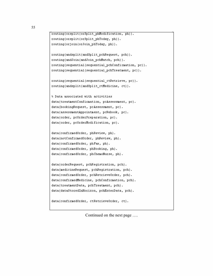
55
Continued on the next page ….
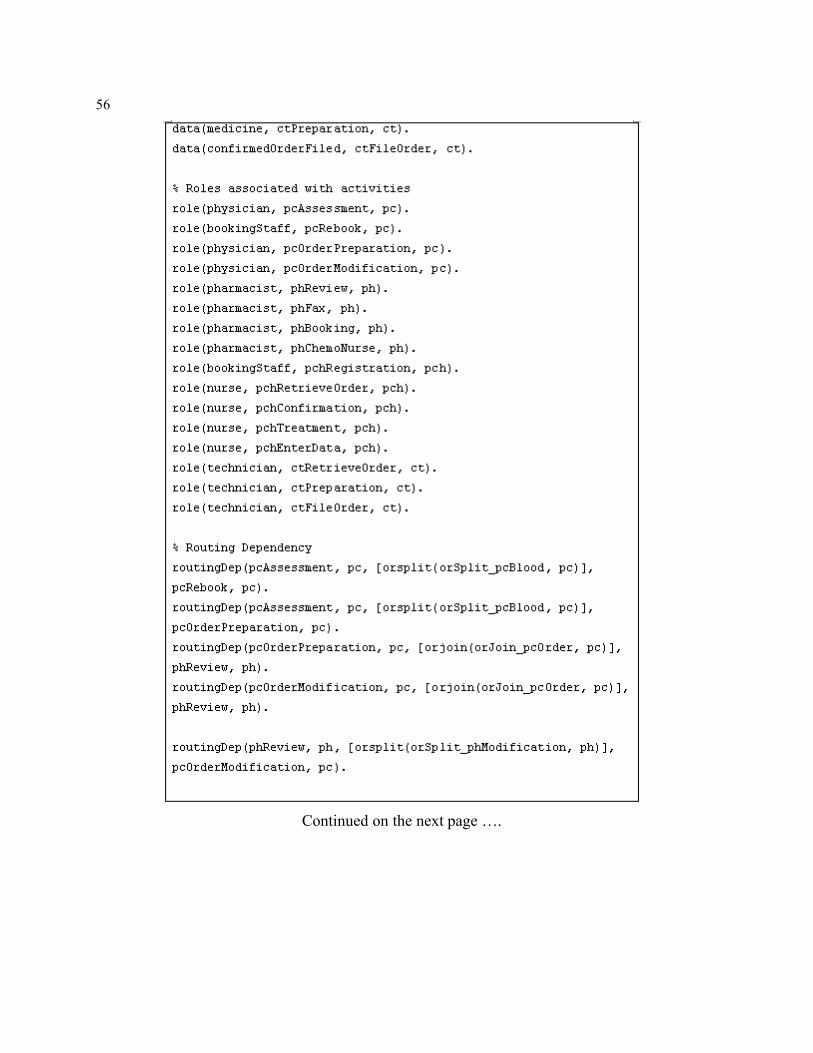
56
Continued on the next page ….
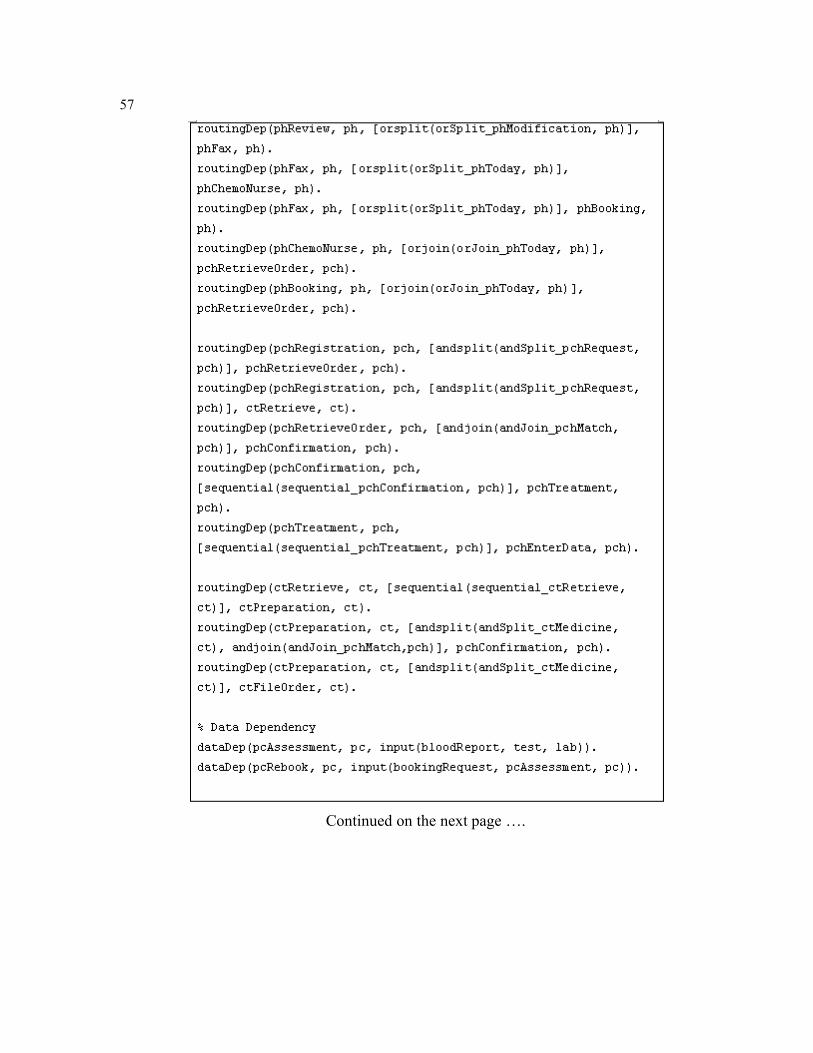
57
Continued on the next page ….
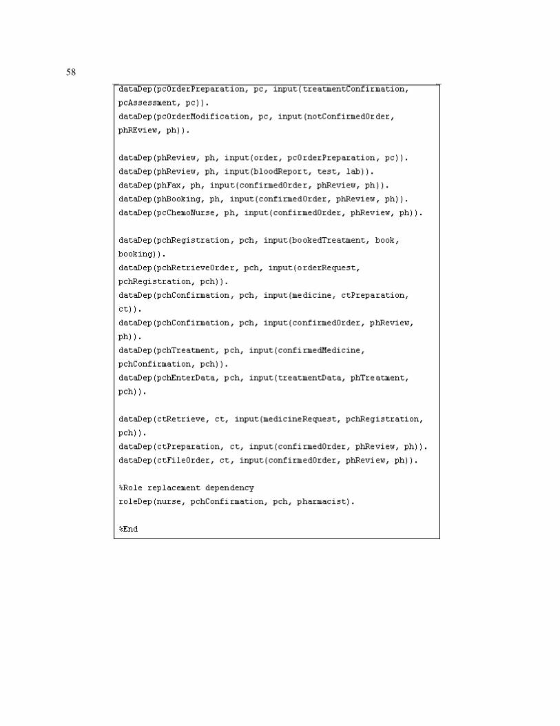
58

59
Bibliography
[1] S. Ajila, Software Maintenance: An Approach to Impact Analysis of Objects Change, Software-Practice and Experience, Vol. 25 (10), pp. 1155 - 1181, 1995. [2] N. R. Adam, V. Atluri, W. Huang, Modeling and Analysis of Workflows Using Petri Nets, Journal of Intelligent Information Systems, Volume 10, Issue 2, Special issue on workflow management systems, pp. 131 - 158, 1998. [3] M. Ader, Workflow & Groupware Strategies, Workflow and Business Process Management Comparative Study, 2003 Edition, Volume I. [4] P. Alencar, Previous Work in Workflow Research (Research Proposal), 2004. [5] R. Allen, Workflow: An Introduction, Workflow Handbook, 2001. [6] G. Arango, E. Schoen and R. Pettengill, A Process for Consolidating and Reusing Design Knowledge, Proceedings of the International Conference on Software Engineering, pp. 231 - 242, 1993. [7] E. Baniassad and S. Clarke, Theme: An Approach for Aspect-Oriented Analysis and Design, Proceedings of the 26th International Conference on Software Engineering, pp. 158 - 167, 2004. [8] J. Becker, M. Rosemann, C. v. Uthmann, Guidelines of Business Process Modeling, Business Process Management: Models, Techniques, and Empirical Studies, W. van der Aalst, J. Desel, A. Oberweis (Eds.), LNCS 1806, pp. 30 - 49, 2000. [9] S. A. Bohner, Software Change Impacts an Evolving Perspective, Proceeding IEEE International conference on Software Maintenance, pp. 263 - 272, 2003. [10] S. A. Boher and R. S. Arnold, An Introduction to Software Change Impact Analysis in S. A. Bohner and R. S. Arnold (Eds.), Software Change Impact Analysis, IEEE Computer Society, pp. 1 - 25, 1996. [11] P. Chountas, I. Petrounias, V. Kodogiannis, Temporal Modelling in Flexible Workflows, Computer and Information Sciences - ISCIS 2003, A. Yazici, C. Sener (Eds.), LNCS 2869, pp. 123 - 130, 2003. [12] S.A.Chun, V. Atluri, N. R. Adam, Domain Knowledge-Based Automatic Workflow Generation, Proceedings of Database and Expert Systems Applications: 13th International Conference, DEXA 2002, R. Cicchetti, et al. (Eds.), LNCS 2453, pp. 81 - 93, 2002. [13] N.K. Cicekli, A Temporal Reasoning Approach to Model Workflow Activities, Proceedings of Next Generation Information Technologies and Systems: 4th International Workshop, NGITS '99, R.Y. Pinter, S. Tsur (Eds.), LNCS1649, pp. 256 - 265, 1999. [14] N. K. Cicekli, Y. Yildirim, Formalizing Workflows Using the Event Calculus, Proceedings of 11th International Conference on Database and Expert Systems Applications, DEXA 2000, M. Ibrahim, J. Küng, and N. Revell (Eds.), LNCS 1873, pp. 222 - 231, 2000. [15] L. Deruelle, M. Bouneffa, N. Melab, H. Basson, G. Goncalves and J.C. Nicolas, A Change Impact Analysis Approach For CORBA-Based Federated Databases, Proceedings of 11th International Conference Database and Expert Systems Applications, M. Ibrahim, J. Küng, N. Revell (Eds.), LNCS1873, pp. 949 - 958, 2000. [16] J. Desel, T. Erwin, Modeling, Simulation and Analysis of Business Processes, Business Process Management: Models, Techniques, and Empirical Studies, W. van der Aalst, J. Desel, A. Oberweis (Eds.), LNCS 1806, pp. 129, 2000.
60
[17] Y. Dong, S. Zhang, Modeling Workflow Process Models with Statechart, Proceedings of 10th IEEE International Conference and Workshop on the Engineering of Computer-Based Systems (ECBS’03), pp. 55, 2003. [18] M. Dumas, A.H.M. ter Hofstede, UML Activity Diagrams as a Workflow Specification Language, Proceedings of UML 2001 - The Unified Modeling Language Modeling Languages, Concepts, and Tools: 4th International Conference, 2001, M. Gogolla, C. Kobryn (Eds.), LNCS 2185, pp. 76, 2001. [19] J. Eder, E. Panagos, M. Rabinovich, Time Constraints in Workflow Systems, Proceedings of Advanced Information Systems Engineering: 11th International Conference, CAiSE'99, M. Jarke, A. Oberweis (Eds.), LNCS 1626, pp. 286 - 300, 1999. [20] J. Eder, E. Panagos, H. Pozewaunig and M. Rabinovich, Time Management in Workflow Systems, BIS'99 3rd International Conference on Business Information Systems, pp. 265 - 280, 1999. [21] R. Endl, M. Meyer, Potential of Business Process Modeling with regard to available Workflow Management Systems, Process Modelling, B.S.-Reiter, H.-D. Stahlmann, A. Nethe (Eds.), 1999. [22] K. Fisler, S. Krishnamurthi, L. A. Meyerovich and M. C. Tschantz, Verification and Change-Impact Analysis of Access-Control Policies, ICSE’05, pp. 196 - 205, 2005. [23] G. Fitzgerald, F.A. Siddiqui, Business Process Reengineering and Flexibility: A Case for Unification, The International Journal of Flexible Manufacturing Systems, 14 (2002), pp. 73 - 86, 2002. [24] W. Ge, B. Song, D. Shen, G. Yu, e_SWDL : An XML Based Workflow Definition Language for Complicated Applications in Web Environments, Proceedings of Web Technologies and Applications: 5th Asia-Pacific Web Conference, APWeb 2003, X. Zhou, Y. Zhang, M.E. Orlowska (Eds.), LNCS 2642, pp. 471 - 482, 2003. [25] S. Jablonski, C. Bussler, Workflow Management: Modeling Concepts, Architectures and Implementation, International Thompson Computer Press, 1996. [26] E. Kafeza, D. K.W. Chiu, I. Kafeza, View-Based Contracts in an E-Service Cross-Organizational Workflow Environment, Proceedings of Technologies for E-Services: Second International Workshop, TES 2001, F. Casati, D. Georgakopoulos, M.-C. Shan (Eds.), LNCS 2193, pp. 74 - 88, 2001. [27] G. Kappel, S. Rausch-Schott, W. Retschitzegger, A Framework for Workflow Management System Based on Objects, Rules and Roles, ACM Computing Surveys (CSUR), Volume 32, Issue 1, Article No. 27, 2000. [28] G. Kappel, S. Rausch-Schott, W. Retschitzegger, Coordination in Workflow Management Systems - A Rule-Based Approach, Coordination Technology for Collaborative Applications - Organizations, Processes, and Agents, W. Conen, G. Neumann (Eds.), Springer LNCS 1364, pp. 99 - 120, 1998. [29] K. Kim, Workflow Dependency Analysis and Its Implications on Distributed Workflow Systems, Proceedings of the 17th International Conference on Advanced Information Networking and Applications, pp. 677 – 682, 2003. [30] A. V. Knethen, A Trace Model for System Requirements Changes on Embedded Systems, Proceedings of the 4th International Workshop on Principles of Software Evolution, pp. 17 – 26, 2001.
61
[31] J. Law, G. Rothermel, Whole Program Path-Based Dynamic Impact Analysis, Proceeding of the 25th International Conference on Software Engineering, pp. 308 – 318, 2003. [32] M. Lindvall, K. Sandahl, Traceability Aspects of Impact Analysis in Object-Oriented Systems, Software Maintenance: Research and Practice, Volume 10, pp. 37 - 57, 1998. [33] P. Loos, T. Allweyer, Object-Orientation in Business Process Modeling through Applying Event Driven Process Chains (EPC) in UML, Proceedings of Second International Enterprise Distributed Object Computing Workshop, EDOC '98, pp. 102 - 112, 1998. [34] P. Loos, P. Fettke, Towards an Integration of Business Process Modeling and Object Oriented Software Development, The Proceedings of the Fifth International Symposium on Economic Informatics, Germany, 2001. [35] A. Marcus and J. I. Maletic, Recovering Documentation to Source Code Traceability Links using Latent Semantic Indexing, Proceedings of the 25th International Conference on Software Engineering, pp. 125 - 135, 2003. [36] M. Millie Kwan, P. R. Balasubramanian, Dynamic Workflow Management: A Framework for Modeling Workflows, Proceedings of the Thirtieth Hawaii International Conference on System Sciences, Volume 4, pp. 367, 1997. [37] R. Mohan, M. A. Cohen, and J. Schiefer, A State Machine Based Approach for a Process Driven Development of Web-Applications, Proceedings of Advanced Information Systems Engineering: 14 International conference, CAiSE 2002 Toronto, A. Banks Pidduck, et al. (Eds.), pp. 52, 2002. [38] L. Moonen, Lightweight Impact Analysis using Island Grammars, Proceedings of the 10th International Workshop on Program Comprehension, pp. 219, 2002. [39] H.A. Reijers, Design and Control of Workflow Processes, LNCS 2617, pp. 1 - 29, 2003. [40] H. A. Reijers, Design and Control of Workflow Processes, LNCS2617, pp. 31 - 59, 2003. [41] Y. Ren, K.F. Wong, B.T. Low, An Integrated Approach for Flexible Workflow Modeling, L.C.-K Hui, D.L. Lee (Eds), ICSC’99, LNCS 1749, pp. 356 - 362, 1999. [42] M. P. Robillard and G. C. Murphy, Concern Graphs Finding and Describing Concerns Using Structural Program Dependencies, Proceedings of the 24th International Conference on Software Engineering, pp. 406 – 416, 2002. [43] B. G. Ryder and F. Tip, Change Impact Analysis for Object-Oriented Programs, PASTE’01, pp. 46 –53, 2001. [44] S. Sadiq, M. Orlowska, W. Sadiq and C. Foulger, Data Flow and Validation in Workflow Modeling, ADC’2004, Conferences in Research and Practice in Information Technology, Vol. 27, K. Schewe, H. Williams (Eds.), pp. 207 –214, 2004. [45] H. Tretteberg, Modeling Work: Workflow and Task Modeling, 1999 International Conference on Computer-Aided Design of User Interfaces, 1999. [46] V. Weerakkody, W. Currie, Integrating Business Process Reengineering with Information Systems Development: Issues & Implications, BPM 2003, W.M.P. van der Aalst et al. (Eds.), LNCS 2678, pp. 302 - 320, 2003. [47] G. Wirtz, H. Giese, Using UML and object-coordination-nets for workflow specification, IEEE International Conference on Systems, Man, and Cybernetics, 2000, Volume: 5, pp. 3159 - 3164, 2000.
62
[48] Workflow Management Coalition, Terminology & Glossary, Document Number WFMC-TC-1101 (Issue 3.0), February 1999. [49] Workflow Management Coalition, http://www.wfmc.org. [50] Workflow Management Coalition, The Workflow Reference Model, Document Number WFMC-TC00-1003 (Issue 1.1), 1995. [51] XSB Programming System, http://www.cs.sunysb.edu/~sbprolog/xsb-page.html. [52] H. D. Covvey, D. Zitner, R. M. Bernstein, Pointing the Way: Competencies and curricula in Health Informatics, 2001.


![Introduction to Dependency Grammar [0.2cm] and Dependency ...ufal.mff.cuni.cz/~bejcek/parseme/prague/Nivre1.pdf · Introduction to Dependency Grammar and Dependency Parsing Joakim](https://img.dokumen.tips/doc/110x75/5b14bded7f8b9a201a8b9282/introduction-to-dependency-grammar-02cm-and-dependency-ufalmffcuniczbejcekparsemeprague.jpg)