Embed Size (px)
Citation preview

Quarry: Digging Up the Gems of Your Data Treasury
Petar JovanovicUniversitat Politècnica deCatalunya, BarcelonaTech
Barcelona, [email protected]
Oscar RomeroUniversitat Politècnica deCatalunya, BarcelonaTech
Barcelona, [email protected]
Alkis SimitsisHP Labs
Palo Alto, CA, [email protected]
Alberto AbellóUniversitat Politècnica deCatalunya, BarcelonaTech
Barcelona, [email protected]
Héctor CandónUniversitat Politècnica deCatalunya, BarcelonaTech
Barcelona, [email protected]
Sergi NadalUniversitat Politècnica deCatalunya, BarcelonaTech
Barcelona, [email protected]
ABSTRACTThe design lifecycle of a data warehousing (DW) system isprimarily led by requirements of its end-users and the com-plexity of underlying data sources. The process of design-ing a multidimensional (MD) schema and back-end extract-transform-load (ETL) processes, is a long-term and mostlymanual task. As enterprises shift to more real-time and ’on-the-fly’ decision making, business intelligence (BI) systemsrequire automated means for e�ciently adapting a physicalDW design to frequent changes of business needs. To ad-dress this problem, we present Quarry, an end-to-end sys-tem for assisting users of various technical skills in manag-ing the incremental design and deployment of MD schemataand ETL processes. Quarry automates the physical designof a DW system from high-level information requirements.Moreover, Quarry provides tools for e�ciently accommodat-ing MD schema and ETL process designs to new or changedinformation needs of its end-users. Finally, Quarry facili-tates the deployment of the generated DW design over anextensible list of execution engines. On-site, we will use avariety of examples to show how Quarry facilitates the com-plexity of the DW design lifecycle.
1. INTRODUCTIONTraditionally, the process of designing a multidimensional
(MD) schema and back-end extract-transform-load (ETL)flows, is a long-term and mostly manual task. It usuallyincludes several rounds of collecting requirements from end-users, reconciliation, and redesigning until the business needsare finally satisfied. Moreover, in today’s BI systems, de-ployed DW systems, satisfying the current set of require-ments is subject to frequent changes as the business evolves.MD schema and ETL process, as other software artifacts, donot lend themselves nicely to evolution events and in general,
c�2015, Copyright is with the authors. Published in Proc. 18th Inter-national Conference on Extending Database Technology (EDBT), March23-27, 2015, Brussels, Belgium: ISBN 978-3-89318-067-7, on OpenPro-ceedings.org. Distribution of this paper is permitted under the terms of theCreative Commons license CC-by-nc-nd 4.0
maintaining them manually is hard. First, for each new,changed, or removed requirement, an updated DW designmust go through a series of validation processes to guaran-tee the satisfaction of the current set of requirements, andthe soundness of the updated design solutions (i.e., meetingMD integrity constraints [9]). Moreover, the proposed de-sign solutions should be further optimized to meet di↵erentquality objectives (e.g., performance, fault tolerance, struc-tural complexity). Lastly, complex BI systems may usuallyinvolve a plethora of execution platforms, each one special-ized for e�ciently performing a specific analytical process-ing. Thus the e�cient deployment over di↵erent executionsystems is an additional challenge.
Translating information requirements into MD schema andETL process designs has been already studied, and variousworks propose either manual (e.g., [8]), guided (e.g., [1]) orautomated [2, 10, 11] approaches for the design of a DWsystem. In addition, in [4] a tool (a.k.a. Clio) is proposed toautomatically generate correspondences (i.e., schema map-pings) among di↵erent existing schemas, while another tool(a.k.a. Orchid) [3] further provides interoperability betweenClio and procedural ETL tools. However, Clio and Orchiddo not tackle the problem of creating a target schema. More-over, none of these approaches have dealt with automatingthe adaptation of a DW design to new information needs ofits end-users, or the complete lifecyle of a DW design.
To address these problems, we built Quarry, an end-to-end system for assisting users in managing the complexityof the DW design lifecycle.
Quarry starts from high-level information requirementsexpressed in terms of analytical queries that follow the well-known MD model. That is, having a subject of analysis andits analysis dimensions (e.g., Analyze the revenue from thelast year’s sales, per products that are ordered from Spain.).Quarry provides a graphical assistance tool for guiding non-expert users in defining such requirements using a domain-specific vocabulary. Moreover, Quarry automates the pro-cess of validating each requirement with regard to the MDintegrity constraints and its translation into MD schema andETL process designs (i.e., partial designs).
Independently of the way end-users translate their infor-mation requirements into the corresponding partial designs,Quarry provides automated means for integrating these MDschema and ETL process designs into a unified DW designsatisfying all requirements met so far.
549 10.5441/002/edbt.2015.55

Figure 1: Quarry: system overview
Quarry automates the complex and time-consuming taskof the incremental DW design. Moreover, while integrat-ing partial designs, Quarry provides an automatic valida-tion, both regarding the soundness (e.g., meeting MD in-tegrity constraints) and the satisfiability of the current busi-ness needs. Finally, for leading the automatic integration ofMD schema and ETL process designs, and creating an opti-mal DW design solution, Quarry accounts for user-specifiedquality factors (e.g., structural design complexity of an MDschema, overall execution time of an ETL process).
Since Quarry assists both MD schema and ETL processdesigns, it also e�ciently supports the additional iterativeoptimization steps of the complete DW design. For example,more complex ETL flows may be required to reduce thecomplexity of an MD schema and improve the performanceof OLAP queries by pre-aggregating and joining source data.
Besides e�ciently supporting the traditional DW design,the automation that Quarry provides, largely suits the needsof modern BI systems requiring rapid accommodation of adesign to satisfy frequent changes.
Outline. We first provide an overview of Quarry andthen, we present its core features to be demonstrated. Lastly,we outline our on-site presentation.
2. DEMONSTRABLE FEATURESQuarry presents an end-to-end system for managing the
DW design lifecycle. Thus, it comprises four main compo-nents (see Figure 1): Requirements Elicitor, RequirementsInterpreter, Design Integrator, and Design Deployer.
For supporting non-expert users in providing their infor-mation requirements at input, Quarry provides a graphicalcomponent, namely Requirements Elicitor (see Figure 2).Requirements Elicitor then connects to a component (i.e.,Requirements Interpreter), which for each information re-quirement at input semi-automatically generates validatedMD schema and ETL process designs (i.e., partial designs).Quarry further o↵ers a component (i.e., Design Integra-tor) comprising two modules for integrating partial MD sch-ema and ETL process designs processed so far, and gener-ating unified design solutions satisfying a complete set ofrequirements. At each step, after integrating partial designsof a new requirement, Quarry guarantees the soundness ofthe unified design solutions and the satisfiability of all re-
Figure 2: Requirements Elicitor
quirements processed so far. The produced DW design solu-tions are further sent to the Design Deployer component forthe initial deployment of a DW schema and an ETL processthat populates it. The deployed design solutions are thenavailable for further user-preferred tunings and use.
To support intra and cross-platform communication, Qua-rry uses the communication & metadata layer (see Figure 1).
2.1 Requirements ElicitorRequirements Elicitor uses a graphical representation of a
domain ontology capturing the underlying data sources. Adomain ontology can be additionally enriched with the busi-ness level vocabulary, to enable non-expert users to expresstheir analytical needs. Notice for example a graphical repre-sentation of an ontology capturing the TPC-H1 data sourcesin top-left part of Figure 2. Apart from manually definingrequirements from scratch, Requirements Elicitor also o↵ersassistance to end-users’ data exploration tasks by analyz-ing the relationships in the domain ontology, and automat-ically suggesting potentially interesting analytical perspec-tives. For example, a user may choose the focus of an anal-
1http://www.tpc.org/tpch/
550
Deployable design solutions
<MDschema> <facts> <fact> <name>fact_table_revenue</name> ...
<MDschema> <facts> <fact> <name>fact_table_revenue</name> ...
<MDschema> <facts> <fact> <name>fact_table_revenue</name> ...
<design> <metadata>...</metadata> <edges> <edge> <from>DATASTORE_Partsupp</from>
<design> <metadata>...</metadata> <edges> <edge> <from>DATASTORE_Partsupp</from>
<design> <metadata>...</metadata> <edges> <edge> <from>DATASTORE_Partsupp</from>...
Partial designs
<MDschema> <facts> <fact> <name>fact_table_revenue</name> ...
<MDschema> <facts> <fact> <name>fact_table_revenue</name> ...
<MDschema> <facts> <fact> <name>fact_table_netprofit</name> ...
<design> <metadata>...</metadata> <edges> <edge> <from>DATASTORE_Partsupp</from>
<design> <metadata>...</metadata> <edges> <edge> <from>DATASTORE_Partsupp</from>
<design> <metadata>...</metadata> <edges> <edge> <from>DATASTORE_Nation</from>...
...
...
IR 1
IR N
IR 1
IR N
MD schema (xMD)
ETL process (xLM)
Unified design solutions (IR 1 – IR N)
<MDschema> <facts> <fact> <name>fact_table_revenue</name> ...
<MDschema> <facts> <fact> <name>fact_table_revenue</name> ...
<MDschema> <facts> <fact> <name>fact_table_revenue</name> …<MDschema> <facts> <fact> <name>fact_table_netprofit</name> ...
<design> <metadata>...</metadata> <edges> <edge> <from>DATASTORE_Partsupp</from>
<design> <metadata>...</metadata> <edges> <edge> <from>DATASTORE_Partsupp</from>
<design> <metadata>...</metadata> <edges> <edge> <from>DATASTORE_Partsupp</from> <to>EXTRACTION_Partsupp</to> <enabled>Y</enabled> </edge> … </edges> <nodes> <node> <name>DATASTORE_Partsupp</name> <type>Datastore</type>...
MDInt.
ETLInt.
CREATE DATABASE demo; CREATE TABLE fact_table_revenue (
Partsupp_PartsuppID BIGINT… ,Orders_OrdersID BIGINT …,revenue double precision ,
PRIMARY KEY( Partsupp_PartsuppID, Orders_OrdersID )
); …CREATE TABLE fact_table_netprofit (
...); ...
<transformation> <connection> … <database>demo</database>...<order> <hop> <from>DATASTORE_Partsupp</from> <to>EXTRACTION_Partsupp</to> <enabled>Y</enabled> </hop> …<step> <name>DATASTORE_Partsupp</name> <type>TableInput</type> ...
MD schema (xMD)
ETL process (xLM)
MD schema (SQL, RDBMS)
MDdep.
ETL process (Pentaho PDI)
ETLdep.
Figure 3: Design integration & deployment example
ysis (e.g., Lineitem), while the system then automaticallysuggests useful dimensions (e.g., Supplier, Nation, Part).The user can further accept or discard the suggestions andsupply her information requirement.
2.2 Requirements InterpreterEach information requirement defined by a user, is then
translated by the Requirements Interpreter to a partial DWdesign. In particular, Requirements Interpreter maps an in-put information requirement to underlying data sources (i.e.,by means of a domain ontology that captures them and cor-responding source schema mappings; see Section 2.5), andsemi-automatically generates MD schema and ETL processdesigns that satisfy such requirement. For more details anda discussion on correctness we refer the reader to [11].
In addition, Quarry allows plugging in other external de-sign tools, with the assumption that the provided partialdesigns are sound (i.e., meet MD integrity constraints) andthat they satisfy an end-user requirement. To enable suchcross-platform interoperability, Quarry provides logical, pla-tform-independent representations (see Section 2.5). Gener-ated designs are stored to the Communication & Metadatalayer using corresponding formats and related to the infor-mation requirements they satisfy.
2.3 Design IntegratorStarting from each information requirement, translated to
corresponding partial MD schema and ETL process designs,Quarry takes care of incrementally consolidating these de-signs and generating unified design solutions satisfying allcurrent requirements (see Figure 3).MD Schema Integrator. This module semi-automatica-
lly integrates partial MD schemas. MD Schema Integrator,comprises four stages, namely matching facts, matching di-mensions, complementing the MD schema design, and in-tegration. The first three stages gradually match di↵erentMD concepts and explore new DW design alternatives. Thelast stage considers these matchings and end-user’s feedbackto generate the final MD schema that accommodates newinformation requirements. To boost the integration of newinformation requirements spanning diverse data sources intothe final MD schema design, we capture the semantics (e.g.,concepts, properties) of the available data sources in terms ofa domain ontology and corresponding source schema map-pings (see Section 2.5). MD Schema Integrator automat-ically guarantees MD-compliant results and produces theoptimal solution by applying cost models that capture dif-ferent quality factors (e.g., structural design complexity).
<MDschema> <facts> <fact> <name>fact_table_revenue</name> ... </facts> <dimensions> <dimension> <name>Part</name> ... </dimensions></MDschema>
<MDschema> <facts> <fact> <name>fact_table_revenue</name> ... </facts> <dimensions> <dimension> <name>Part</name> ... </dimensions></MDschema>
<MDschema> <facts> <fact> <name>fact_table_revenue</name> ... </facts> <dimensions> <dimension> <name>Part</name> ... </dimensions></MDschema>
<cube> <dimensions> <concept id="Part_p_nameATRIBUT"/> <concept id="Supplier_s_nameATRIBUT"/> </dimensions> <measures> <concept id="revenue"> <function> Lineitem_l_extendedpriceATRIBUT * Lineitem_l_discountATRIBUT</function> </concept> </measures> <slicers> <comparison> <concept id="Nation_n_nameATRIBUT"/> <operator>=</operator> <value>Spain</value> </comparison> </slicers>…
... <aggregations> <aggregation order="1"> <dimension refID="Part_p_nameATRIBUT"/> <measure refID="revenue"/> <function>AVERAGE</function> </aggregation> <aggregation order="1"> <dimension refID="Supplier_s_nameATRIBUT"/> <measure refID="revenue"/> <function>AVERAGE</function> </aggregation> </aggregations></cube>
to xRQ
<design> <metadata>...</metadata> <edges> <edge> <from>DATASTORE_Partsupp</from> <to>EXTRACTION_Partsupp</to> <enabled>Y</enabled> </edge> … </edges> <nodes> <node> <name>DATASTORE_Partsupp</name> <type>Datastore</type> <optype>TableInput</optype> ... </nodes> … </design>
<design> <metadata>...</metadata> <edges> <edge> <from>DATASTORE_Partsupp</from> <to>EXTRACTION_Partsupp</to> <enabled>Y</enabled> </edge> … </edges> <nodes> <node> <name>DATASTORE_Partsupp</name> <type>Datastore</type> <optype>TableInput</optype> ... </nodes> … </design>
<design> <metadata>...</metadata> <edges> <edge> <from>DATASTORE_Partsupp</from> <to>EXTRACTION_Partsupp</to> <enabled>Y</enabled> </edge> … </edges> <nodes> <node> <name>DATASTORE_Partsupp</name> <type>Datastore</type> <optype>TableInput</optype> ... </nodes> … </design>
to xMD
to xLM
Partial designs
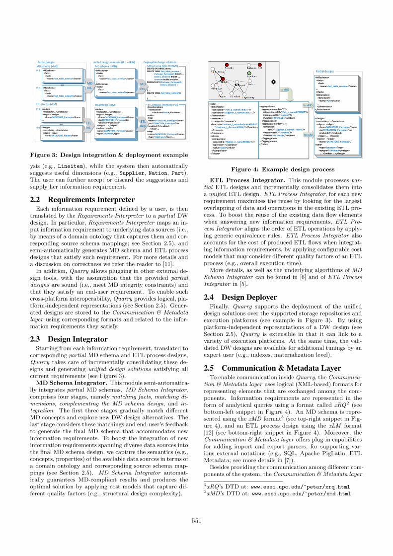
Figure 4: Example design process
ETL Process Integrator. This module processes par-tial ETL designs and incrementally consolidates them intoa unified ETL design. ETL Process Integrator, for each newrequirement maximizes the reuse by looking for the largestoverlapping of data and operations in the existing ETL pro-cess. To boost the reuse of the existing data flow elementswhen answering new information requirements, ETL Pro-cess Integrator aligns the order of ETL operations by apply-ing generic equivalence rules. ETL Process Integrator alsoaccounts for the cost of produced ETL flows when integrat-ing information requirements, by applying configurable costmodels that may consider di↵erent quality factors of an ETLprocess (e.g., overall execution time).
More details, as well as the underlying algorithms of MDSchema Integrator can be found in [6] and of ETL ProcessIntegrator in [5].
2.4 Design DeployerFinally, Quarry supports the deployment of the unified
design solutions over the supported storage repositories andexecution platforms (see example in Figure 3). By usingplatform-independent representations of a DW design (seeSection 2.5), Quarry is extensible in that it can link to avariety of execution platforms. At the same time, the vali-dated DW designs are available for additional tunings by anexpert user (e.g., indexes, materialization level).
2.5 Communication & Metadata LayerTo enable communication inside Quarry, the Communica-
tion & Metadata layer uses logical (XML-based) formats forrepresenting elements that are exchanged among the com-ponents. Information requirements are represented in theform of analytical queries using a format called xRQ2 (seebottom-left snippet in Figure 4). An MD schema is repre-sented using the xMD format3 (see top-right snippet in Fig-ure 4), and an ETL process design using the xLM format[12] (see bottom-right snippet in Figure 4). Moreover, theCommunication & Metadata layer o↵ers plug-in capabilitiesfor adding import and export parsers, for supporting var-ious external notations (e.g., SQL, Apache PigLatin, ETLMetadata; see more details in [7]).
Besides providing the communication among di↵erent com-ponents of the system, the Communication & Metadata layer
2xRQ ’s DTD at: www.essi.upc.edu/~petar/xrq.html3xMD ’s DTD at: www.essi.upc.edu/~petar/xmd.html
551

also serves as a repository for the metadata that are pro-duced and used during the DW design lifecycle. The meta-data used to boost the semantic-aware integration of DW de-signs inside the Quarry platform, are domain ontologies cap-turing the semantics of underlying data sources, and sourceschema mappings that define the mappings of the ontologi-cal concepts in terms of underlying data sources.
2.6 Implementation detailsQuarry has been developed at UPC, BarcelonaTech in the
last three years, using a service-oriented architecture.On the client side, Quarry provides a web-based compo-
nent for assisting end-users during the DW lifecycle (i.e.,Requirements Elicitor). This component is implemented inJavaScript, using the specialized D3 library for visualizingdomain ontologies in form of graphs. The rest of modules(i.e., Requirements Interpreter, MD Schema Integrator, andETL Process Integrator) are deployed on Apache Tomcat7.0.34, with their functionalities o↵ered via HTTP-basedRESTful APIs. Such architecture provides the extensibilityto Quarry for easily plugging and o↵ering new componentsin the future (e.g., design self-tuning). Currently, all mod-ule components are implemented in Java 1.7, whilst newmodules can internally use di↵erent technologies. For gen-erating internal XML formats (i.e., xRQ, xMD, xLM ) wecreated a set of Apache Velocity 1.7 templates, while fortheir parsing we rely on the Java SAX parser. For repre-senting domain ontology inside Quarry, we used Web Ontol-ogy Language (OWL), and for internally handling the ontol-ogy objects inside Java, we used the Apache Jena libraries.Lastly, the Communication & Metadata layer, which im-plements communication protocols among di↵erent compo-nents in Quarry, uses a MongoDB instance as a storagerepository, and a generic XML-JSON-XML parser for read-ing from and writing to the repository.
3. DEMONSTRATIONIn the on-site demonstration, we will present the function-
ality of Quarry, using our end-to-end system for assistingusers in managing the DW design lifecycle (see Figure 1).We will use di↵erent examples of synthetic and real-worlddomains, covering a variety of underlying data sources, anda set of representative information requirements from thesedomains depicting typical scenarios of the DW design life-cycle. Demo participants will be especially encouraged toprovide example analytical needs using Requirements Elici-tor, and play the role of Quarry ’s end-users. The followingscenarios will be covered by our on-site demonstration.DW design. Business users are not expected to have deep
knowledge of the underlying data sources, thus they maychoose to pose their information requirements using the do-main vocabulary. To this end, business users may use thegraphical component of Quarry (i.e., Requirements Elici-tor), and its graphical representation of a domain ontol-ogy. This scenario shows how Quarry supports non-expertusers in the early phases of the DW design lifecycle, to ex-press their analytical needs (i.e., through assisted data ex-ploration of Requirements Elicitor), and to easily obtain theinitial DW design solutions.Accommodating a DW design to changes. Due to possi-
ble changes in a business environment, a new informationrequirement could be posed or existing requirements mightbe changed or even removed from the analysis. Designers
thus must reconsider the complete DW design to take intoaccount the incurred changes. This scenario demonstrateshow Quarry e�ciently accommodates these changes and in-tegrate them by producing an optimal DW design solution.We will consider structural design complexity as an examplequality factor for output MD schemata, and overall execu-tion time for ETL processes. The participants will see thebenefits of integrated DW design solutions (e.g., reducedoverall execution time for integrated ETL processes, exe-cuted in Pentaho PDI).
Design deployment. Finally, after the involved partiesagree upon the provided solution, the chosen design is de-ployed on the available execution platforms. In this sce-nario, we will show how Quarry facilitates this part of thedesign lifecycle and generates corresponding executables forthe chosen platforms. We use PostgreSQL for deploying ourMD schema solutions, while for running the correspondingETL flows, we use Pentaho PDI.
4. REFERENCES[1] Z. E. Akkaoui, E. Zimanyi, J.-N. Mazon, and
J. Trujillo. A BPMN-Based Design and MaintenanceFramework for ETL Processes. IJDWM, 9(3):46–72,2013.
[2] L. Bellatreche, S. Khouri, and N. Berkani. SemanticData Warehouse Design: From ETL to Deployment ala Carte. In DASFAA (2), pages 64–83, 2013.
[3] S. Dessloch, M. A. Hernandez, R. Wisnesky,A. Radwan, and J. Zhou. Orchid: Integrating SchemaMapping and ETL. In ICDE, pages 1307–1316, 2008.
[4] R. Fagin, L. M. Haas, M. A. Hernandez, R. J. Miller,L. Popa, and Y. Velegrakis. Clio: Schema MappingCreation and Data Exchange. In Conceptual Modeling:Foundations and Applications, pages 198–236.Springer, 2009.
[5] P. Jovanovic, O. Romero, A. Simitsis, and A. Abello.Integrating ETL processes from informationrequirements. In DaWaK, pages 65–80, 2012.
[6] P. Jovanovic, O. Romero, A. Simitsis, A. Abello, andD. Mayorova. A requirement-driven approach to thedesign and evolution of data warehouses. Inf. Syst.,44:94–119, 2014.
[7] P. Jovanovic, A. Simitsis, and K. Wilkinson. Engineindependence for logical analytic flows. In ICDE,pages 1060–1071, 2014.
[8] R. Kimball, L. Reeves, W. Thornthwaite, andM. Ross. The Data Warehouse Lifecycle Toolkit. J.Wiley & Sons, 1998.
[9] J.-N. Mazon, J. Lechtenborger, and J. Trujillo. Asurvey on summarizability issues in multidimensionalmodeling. Data Knowl. Eng., 68(12):1452–1469, 2009.
[10] C. Phipps and K. C. Davis. Automating datawarehouse conceptual schema design and evaluation.In DMDW, volume 58 of CEUR WorkshopProceedings, pages 23–32, 2002.
[11] O. Romero, A. Simitsis, and A. Abello. GEM:Requirement-Driven Generation of ETL andMultidimensional Conceptual Designs. In DaWaK,pages 80–95, 2011.
[12] A. Simitsis and K. Wilkinson. The specification forxLM: an encoding for analytic flows, HP TechnicalReport, 2015.
552