Embed Size (px)
Citation preview
ISSN 0025-6544, Mechanics of Solids, 2010, Vol. 45, No. 2, pp. 264–274. c© Allerton Press, Inc., 2010.Original Russian Text c© V.I. Gulyaev, O.V. Glushakova, S.N. Khudolii, 2010, published in Izvestiya Akademii Nauk. Mekhanika Tverdogo Tela, 2010, No. 2, pp. 134–147.
Quantized Attractors in Wave Modelsof Torsion Vibrations of Deep-Hole Drill Strings
V. I. Gulyaev*, O. V. Glushakova**, and S. N. Khudolii***
National Transport University,Suvorova 1, Kiev, 01010 Ukraine
Received October 13, 2008
Abstract—We pose the problem of self-excitation of elastic wave torsional vibrations of a rotatingdrill string, which arise as a result of frictional interaction of the drill bit with the rock at the bottomof the deep hole. We use d’Alembert’s solution of the wave equation to construct a mathematicalmodel of the wave torsion pendulum in the form of a nonlinear ordinary differential equation withretarded argument. We show that there exists a range of variation in the angular velocity ofthe drill string rotation, where, along with the unstable stationary solution characterized by theabsence of vibrations, there are oscillatory solutions in the form of a stable limit cycle (attractor).The self-excitation of these vibrations is soft, and the self-oscillations themselves belong to theclass of relaxation vibrations, because their period can be divided into several separated intervalscorresponding to slow and fast variations in the state of the system. The velocities of the drill bitelastic motions on each of these time intervals remain constant, and the durations of all of them arethe same and equal to the time interval (quantum) of the twist mode propagation from the drill bit tothe drill string top and conversely.
DOI: 10.3103/S0025654410020123
Key words: deep-hole drill string, self-excited torsion vibrations, wave model, Hopf bifurca-tion.
1. INTRODUCTION
The energy problems, which become more and more urgent in the 21st century, are to a large extentcaused by the approaching exhaustion of oil and gas resources and by the progressing complication ofconditions of their production. Since the easily accessible oil and gas fields have been exhausted by theirirrational and careless production during the preceding two centuries, their production at depths of 10 kmbecomes perspective. There arise problems of drilling inclined and horizontal wells with horizontaldeviations from the drill hole by distances up to 15 km. Taking into account that the cost of such wells isvery high [1] and, according to the statistics, one out of every three of them is accidental [2], we can notethat the problem of design of accident-free technological regimes of deep-hole drilling is very topical.
One of the dynamic phenomena contributing to the appearance of an off-optimum situation in theprocess of drilling is the self-excitation of torsion vibrations of the rotating drill string. Since a drill stringis a torsion pendulum in whose lower part the energy outflows to the environment due to the dissipationinteraction between the drill bit and the destructed rock, in the case of any violation of the conditionsof this outflow, the drill string may pass from stationary equilibrium to the state of self-excited torsionvibrations.
In the general case, the self-excited vibrations are undamped periodic motions of a nonlineardissipative system maintained by an external nonoscillatory source of energy [3, 4]. For these motionsto be steady, it is important that the force interaction between separate parts of the system be nonlinear,so that this nonlinearity could control the energy flow and expenditure and thus maintain the vibrationamplitude within certain bounds. In the drilling devices, the cause of self-excitation of torsion vibrations
*e-mail: [email protected]**e-mail: [email protected]
***e-mail: [email protected]
264
QUANTIZED ATTRACTORS IN WAVE MODELS OF TORSION VIBRATIONS 265
is the bifurcational violation of the balance of the moments of the elastic forces in the drill string and ofthe nonlinear friction forces between the drill bit and the well hole.
2. SPECIFIC CHARACTERISTICS OF SELF-EXCITATION OF TORSION VIBRATIONSIN EXTENDED DRILL STRING
In the theory of nonlinear differential equations, the periodic solution is called a cycle, and thechange of the stationary equilibrium solution by a periodic solution while a certain characteristicparameter passes through a critical value is called a bifurcation of cycle generation or a Hopf (Poincare–Andronov–Hopf bifurcation) bifurcation. To the periodic self-excited vibrations in the phase space, therecorresponds a closed trajectory (a stable limit cycle) to which all neighboring trajectories are attracted.Therefore, it is called an attractor [3–5].
In problem of the drill string dynamics, a parameter determining their stationary and self-oscillatingregime is the angular velocity ω of rotation. For the phenomena accompanying the drill string rotation,the study of the possibility of generation of their self-excited vibrations permits answering the followingthree questions: for what values of the system parameter and its operation the generation of self-excitedtorsion vibrations is possible, what type of the regime of self-excited vibrations (soft or hard) is possible,and what measures can remove the possible regimes of self-excited torsion vibrations.
For the drill string in comparatively shallow wells, answers to these questions can be obtained byusing a simplified mathematical model constructed on the basis of the rotating torsion pendulum whoseflywheel–drill bit is under the action of nonlinear friction forces of its interaction with the destructed rock.In this case, we can assume that the flywheel and all the drill string elements execute torsion vibrationswith the same phase, and hence the entire elastic system can be replaced by a single oscillator with asingle degree of freedom [6–10]. Such models are complete applicable for the drill string used in the coalindustry in driving shallow shafts of diameter up to 5 m, because the periods of torsion vibrations of theirdrill bits are large and the time of the twist mode propagation through the drill string length is small.
But if the drill string length is not small, then it is unreasonable to use the torsion oscillatorypendulum model to analyze the drill string dynamics, because its elements can execute in-phasevibrations, and their modelling must be based on the wave theory. The necessity of using this theorywas mentioned in [7, 9, 10], although the attempts to solve this problem made there were based on theapproximation of the incident and reflected torsional waves by a monochromatic harmonic.
Under real conditions, this simplification generally does not hold, because the time of the wavepropagation through the drill string length is not a multiple of the period of the lower flywheel vibrations,and its motion may take a complicated form. The flywheel motion shape may be significantly complicatedbecause of the effect of its vibration freezing typical of systems with dry friction. It consists in short-timedwells of the flywheel motion in the time intervals, where the sum of all moments of active forces andmoments of inertial forces is less than a certain threshold moment of friction forces, which must beovercome for the flywheel to begin the rotation.
In these time intervals, the drive mechanism located at the drill string upper end continues to rotatewith an angular velocity ω, the drill string twists, and the potential energy of elastic strain is accumulatedin it. As the elastic moment in the drill string becomes equal to the threshold value of the momentof friction forces, the lower flywheel (the drill bit) begins to rotate, the drill string untwists, and itspotential energy is transformed into the kinetic energy of the drill string and the flywheel rotation. Thisrotation continues until the sum of the drill string elastic moment and the drill bit moment of inertialforces becomes less than the threshold value of friction forces, as the results of which the flywheel againstops, etc. Since, in the described motion, the functions of angular velocities and accelerations becomediscontinuous, the drill string rotation takes the character of impacts, which is most dangerous for thedynamical strength and stability of the entire system. It is nonrational to describe such oscillations bytrigonometric functions, and it is necessary to use numerical methods.
An important factor complicating this effect and the statement of the problem is also the effect ofaction on the flywheel of the torsional waves formed as a result of elastic interaction between the flywheeland the drill string, coming to the upper end of the drill string, reflected from it, and returning to the lowerend with a delay equal to their travel time. The influence of this effect has yet to be studied.
In the present paper, taking the nonlinear frictional interaction between the drill bit and the destructedrock into account, we pose the problem of studying the self-excitation of wave and oscillatory torsionalmotions in the vertical deep-hole drill string and the influence of the effect of the incident twist modedelay on the dynamical process.
MECHANICS OF SOLIDS Vol. 45 No. 2 2010
266 GULYAEV et al.
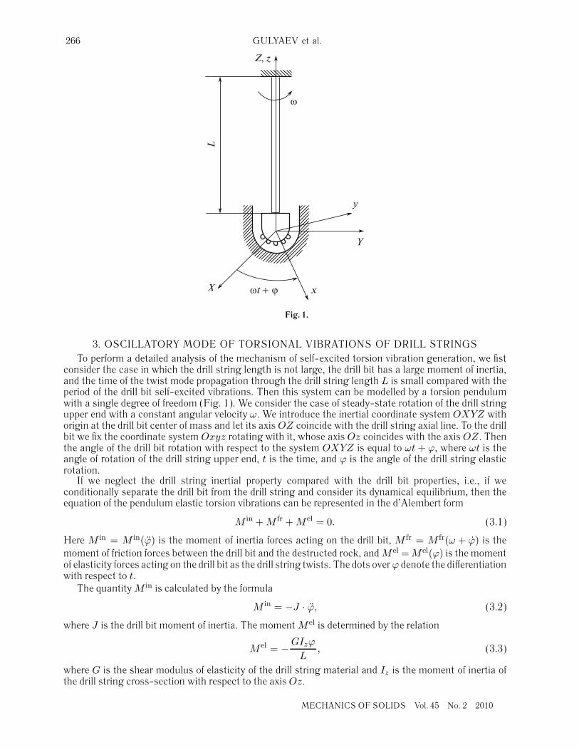
Fig. 1.
3. OSCILLATORY MODE OF TORSIONAL VIBRATIONS OF DRILL STRINGSTo perform a detailed analysis of the mechanism of self-excited torsion vibration generation, we fist
consider the case in which the drill string length is not large, the drill bit has a large moment of inertia,and the time of the twist mode propagation through the drill string length L is small compared with theperiod of the drill bit self-excited vibrations. Then this system can be modelled by a torsion pendulumwith a single degree of freedom (Fig. 1). We consider the case of steady-state rotation of the drill stringupper end with a constant angular velocity ω. We introduce the inertial coordinate system OXYZ withorigin at the drill bit center of mass and let its axis OZ coincide with the drill string axial line. To the drillbit we fix the coordinate system Oxyz rotating with it, whose axis Oz coincides with the axis OZ. Thenthe angle of the drill bit rotation with respect to the system OXYZ is equal to ωt + ϕ, where ωt is theangle of rotation of the drill string upper end, t is the time, and ϕ is the angle of the drill string elasticrotation.
If we neglect the drill string inertial property compared with the drill bit properties, i.e., if weconditionally separate the drill bit from the drill string and consider its dynamical equilibrium, then theequation of the pendulum elastic torsion vibrations can be represented in the d’Alembert form
M in + M fr + M el = 0. (3.1)
Here M in = M in(ϕ) is the moment of inertia forces acting on the drill bit, M fr = M fr(ω + ϕ) is themoment of friction forces between the drill bit and the destructed rock, and M el = M el(ϕ) is the momentof elasticity forces acting on the drill bit as the drill string twists. The dots over ϕ denote the differentiationwith respect to t.
The quantity M in is calculated by the formula
M in = −J · ϕ, (3.2)
where J is the drill bit moment of inertia. The moment M el is determined by the relation
M el = − GIzϕ
L, (3.3)
where G is the shear modulus of elasticity of the drill string material and Iz is the moment of inertia ofthe drill string cross-section with respect to the axis Oz.
MECHANICS OF SOLIDS Vol. 45 No. 2 2010
QUANTIZED ATTRACTORS IN WAVE MODELS OF TORSION VIBRATIONS 267
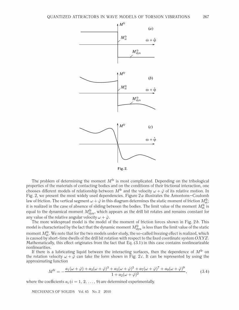
Fig. 2.
The problem of determining the moment M fr is most complicated. Depending on the tribologicalproperties of the materials of contacting bodies and on the conditions of their frictional interaction, onechooses different models of relationship between M fr and the velocity ω + ϕ of its relative motion. InFig. 2, we present the most widely used dependencies. Figure 2 a illustrates the Amontons–Coulomblaw of friction. The vertical segment ω + ϕ in this diagram determines the static moment of friction M fr
st ;it is realized in the case of absence of sliding between the bodies. The limit value of the moment M fr
st isequal to the dynamical moment M fr
dyn, which appears as the drill bit rotates and remains constant forany value of the relative angular velocity ω + ϕ.
The more widespread model is the model of the moment of friction forces shown in Fig. 2 b. Thismodel is characterized by the fact that the dynamic moment M fr
dyn is less than the limit value of the static
moment M frst . We note that for the two models under study, the so-called freezing effect is realized, which
is caused by short-time dwells of the drill bit rotation with respect to the fixed coordinate system OXYZ.Mathematically, this effect originates from the fact that Eq. (3.1) in this case contains nonlinearizablenonlinearities.
If there is a lubricating liquid between the interacting surfaces, then the dependence of M fr onthe rotation velocity ω + ϕ can take the form shown in Fig. 2 c. It can be represented by using theapproximating function
M fr = − a1(ω + ϕ) + a3(ω + ϕ)3 + a5(ω + ϕ)5 + a7(ω + ϕ)7 + a9(ω + ϕ)9
1 + a2(ω + ϕ)2, (3.4)
where the coefficients ai (i = 1, 2, . . . , 9) are determined experimentally.
MECHANICS OF SOLIDS Vol. 45 No. 2 2010
268 GULYAEV et al.
Since the this curve does not have a part with static frictional interaction, the pure freezing effect isimpossible for such an interaction.
We perform the changes (3.2)–(3.4) and write Eq. (3.1) as
Jϕ − M fr(ω + ϕ) +GIz
Lϕ = 0. (3.5)
Its solution for a given ω depends on the form of the function M fr(ω + ϕ). It can be constructednumerically for specific initial conditions with respect to ϕ(0) and ϕ(0). These conditions must be chosentaking into account the fact that the self-excitation of vibrations can be either soft or hard.
4. WAVE MODEL OF TORSION VIBRATIONS OF LONG DRILL STRINGS
The dynamics of rotation of the drill bit suspended at the end of a deep-hole drill string has specificcharacteristics typical of waveguide systems. Since, for such systems, the perturbation applied to oneend attains the other end in a finite time interval, one must take the retardation of such perturbations intoaccount. Indeed, if, for example, the drill string is made of steel, then the velocities of the longitudinaland transverse waves expressed in terms of the moduli of elasticity E, G and the density ρ are equalto α =
√E/ρ ≈ 5100 m/s and β =
√G/ρ ≈ 3200 m/s, respectively, and for L = 600 m, the twisting
perturbation applied to one of its ends attains the other end and returns only in 4 s. Therefore, it isnecessary to study the dynamics of torsion vibrations of such a drill string by using the wave equation
ρIz∂2ϕ
∂t2− GIz
∂2ϕ
∂z2= 0.
By using the substitution β =√
G/ρ, we reduce it to the standard form
∂2ϕ
∂t2− β2 ∂2ϕ
∂z2= 0. (4.1)
It has a solution in the d’Alembert form
ϕ(z, t) = f(z − βt) + g(z + βt), (4.2)
where f(z − βt) and g(z + βt) are arbitrary continuous not necessarily differentiable functions. Thefirst determines the wave propagating in the positive direction of the axis Oz, the second, the wavepropagating in the opposite direction. Since these waves are nondispersive, they propagate preservingtheir profile, which significantly simplifies the process of solving the problem. Indeed, in this case, thefunctions f(z − βt) and g(z + βt) for t > 0 are determined only by the initial conditions
f(z − 0) = f0(z), g(z + 0) = g0(z) (4.3)
and the boundary conditions
F [f(0 − βt), g(0 + βt)] = 0, f(L − βt) + g(L + βt) = 0, (4.4)
where F is a nonlinear differential operator describing the drill bit motion.The first condition in system (4.4) is formed by Eq. (3.1), where M in is determined by formula (3.2),
M fr is represented by one of the diagrams in Fig. 2, and M el is calculated by using the relation
M el = GIz∂ϕ
∂z, (4.5)
where the angular strain ∂ϕ/∂z is calculated as
∂ϕ
∂z
∣∣∣∣z=0
=∂
∂z[f(z − βt) + g(z + βt)]z=0.
From the second relation in system (4.4), we obtain
g(L + βt) = −f(L − βt).
MECHANICS OF SOLIDS Vol. 45 No. 2 2010
QUANTIZED ATTRACTORS IN WAVE MODELS OF TORSION VIBRATIONS 269
Then
ϕ = f(z − βt) − f(2L − z − βt) = f(u) − f(w),u = z − βt, w = 2L − z − βt.
(4.6)
For z = 0, we have
ϕ(0, t) = f(−βt) − f(2L − βt) = f(−βt) − f [−β(t − 2L/β)]. (4.7)
Thus, at the point z = 0 of the drill bit junction to the drill string, the angle of the drill stringtwist ϕ(0, t) is determined by the current values of the function f(−βt) and by its past value f(2L− βt),which took place at this point at the time instant shift to the past by the value T = 2L/β. This meansthat the angle ϕ(0, t) is a function not only of the current value of the argument t but also of theargument (t − 2L/β) with time delay.
It follows from (4.6) that
∂ϕ
∂z=
∂f(u)∂z
− ∂f(w)∂z
=∂f(u)
∂u+
∂f(w)∂w
,
∂ϕ
∂t=
∂f(u)∂t
− ∂f(w)∂t
= −β∂f(u)
∂u+ β
∂f(w)∂w
.
Comparing these relations, we obtain
∂ϕ
∂z= − ∂f(z − βt)
β ∂t− ∂f(2L − z − βt)
β ∂t, (4.8)
and hence
M el = −GIz
[∂f(z − βt)
β ∂t+
∂f(2L − z − βt)β ∂t
]
z=0
= − GIz
β
[∂f(−βt)
∂t+
∂f(2L − βt)∂t
]
z=0
. (4.9)
Substituting (3.2), (3.4), and (4.9) into (3.1) and taking (4.7) into account, we obtain the nonlinearsecond-order ordinary differential equation with retarded argument
L[f(−βt) − f(2L − βt)] − a1[ω + f(−βt) − f(2L − βt)]1 + a2[ω + f(−βt) − f(2L − βt)]2
+ . . .
+a9[ω + f(−βt) − f(2L − βt)]9
1 + a2[ω + f(−βt) − f(2L − βt)]2+
GIz
β[f(−βt) − f(2L − βt)] = 0. (4.10)
This equation is completely equivalent to the system of the partial differential wave equation (4.1) andthe boundary conditions (4.4), which follows from the condition of the drill bit torsion vibrations at z = 0and the interaction between the incident and reflected waves in the case of rigid (but rotating) fixationat z = L. One can note that Eq. (4.10) does not contain the function f(t) but depends only on its firstand second derivatives. This fact permits decreasing the order of the equation by one, but in practicethe method for constructing the total solution of this equation does not become simpler because of itssignificant nonlinearity. It is more convenient to use the Runge-Kutta method. To this end, we denote
q1(t) = f(−βt), q2(t) = f(−βt),
p1(t) = f(2L − βt), p2(t) = f(2L − βt).(4.11)
Substituting (4.11) into (4.10), we obtain
q1 = q2,
q2 =a1(ω + q2 − p2) + . . . + a9(ω + q2 − p2)9
J [1 + a2(ω + q2 − p2)2]− GIz
Jβ(q2 + p2) + p2.
(4.12)
Here the variables q1(t) and q2(t) are desired, and the functions p1(t), p2(t), and p2(t) are known;they are respectively equal to the functions q1(t − 2L/β), q2(t − 2L/β), and q2(t − 2L/β), which werecalculated earlier at time t − 2L/β.
MECHANICS OF SOLIDS Vol. 45 No. 2 2010
270 GULYAEV et al.
System (4.12) can be integrated numerically for a constant angular velocity ω and the given initial
conditions q1(0) = q(0)1 and q2(0) = q
(0)2 . If we model the process of the beginning of drilling, when
the rotating drill string is lowered and the drill bit enters in contact with the rock on the hole bottom,
then we can set q(0)1 = 0, q
(0)2 = 0, p1(−2L/β) = 0, p2(−2L/β) = 0, and p2(−2L/β) = 0, and, only
after the time t = 2L/β, the variables p1(t), p2(t), p2(t) can take their obtained values. In a similar way,we can solve the problem for the moments of friction forces M fr(ω + ϕ) whose functions are shown inFig. 2 a, b. After these solutions are obtained, we can find the drilling regimes at which the self-excitationof torsion vibrations of the drill bit and the deep-hole drill string is realized, construct the shapes of thesevibrations, and choose the drilling conditions eliminating the system self-excited vibrations.
The above-posed problem concerns the case of stationary rotation, where ω = const. But its state-ment can easily be generalized to unsteady states of the drill string rotation related to the acceleration orbraking regimes.
5. SELF-EXCITATION OF WAVE TORSION VIBRATIONS OF DRILL STRINGS
Depending on the chosen regime of drilling, in the process of operation, the drill string can be in statesof steady-state rotation or self-excited torsion vibrations. The type of these states is determined by thesolution of Eq. (4.10) first depending on the form (3.4) of the function torsion vibrations M fr(ω + ϕ), theangular velocity torsion vibrations ω, the length L, and the inertial and rigidity properties of the system.
An analysis of the drill string dynamics by using the wave torsion pendulum model permits not onlyconfirming the general laws of origination of limit cycles in self-excited systems, but also determiningthe time-quantized character of these oscillations, which is related to the wave torsional motions of thestring body. We used Eqs. (4.12) to study the dynamic behavior of a drill string of length L = 1200 m withthe following rigidity and inertia parameters: G = 8.076 · 1010 Pa, β = 3218 m/s, Iz = 3.12 · 10−5 m4,and J = 3.1 kg·m2. The chosen function M fr(ω + ϕ) is shown in Fig. 2 c; it corresponds to thecoefficient values: a1 = 2400 N·m·s, a2 = 225 s2, a3 = 15000 N·m·s3, a5 = 1 N·m·s5, a7 = 4 N·m·s7,and a9 = −130 N·m·s9.
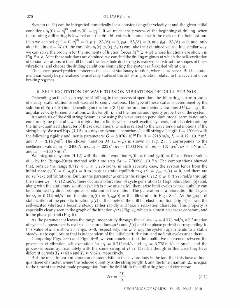
We integrated system (4.12) with the initial condition q1(0) = 0 and q2(0) = 0 for different valuesof ω by the Runge-Kutta method with time step Δt = 7.76898 · 10−6 s. The computations showedthat, outside the range 0.712 � ω � 3.775 rad/s, in each separate case, the system tends from theinitial state q1(0) = 0, q2(0) = 0 to its quasistatic equilibrium q1(t) = ϕst, q2(t) = 0, and there areno self-excited vibrations. But, as the parameter ω enters the range 0.712 � ω � 3.775 rad/s throughthe values ω1 = 0.712 rad/s, there occurs a bifurcation of cycle generation (a Hopf bifurcation [5]) and,along with the stationary solution (which is now unsteady), there arise limit cycles whose stability canbe confirmed by direct computer simulation of the motion. The generation of a bifurcation limit cyclefor ω1 = 0.712 rad/s from the state q1(0) = 0, q2(0) = 0 is illustrated in Figs. 3–5. As the graph ofstabilization of the periodic function ϕ(t) of the angle of the drill bit elastic rotation (Fig. 3) shows, theself-excited vibrations become steady rather rapidly and take a relaxation character. This property isespecially clearly seen in the graph of the function ϕ(t) (Fig. 4), which is almost piecewise constant, andin the phase portrait (Fig. 5).
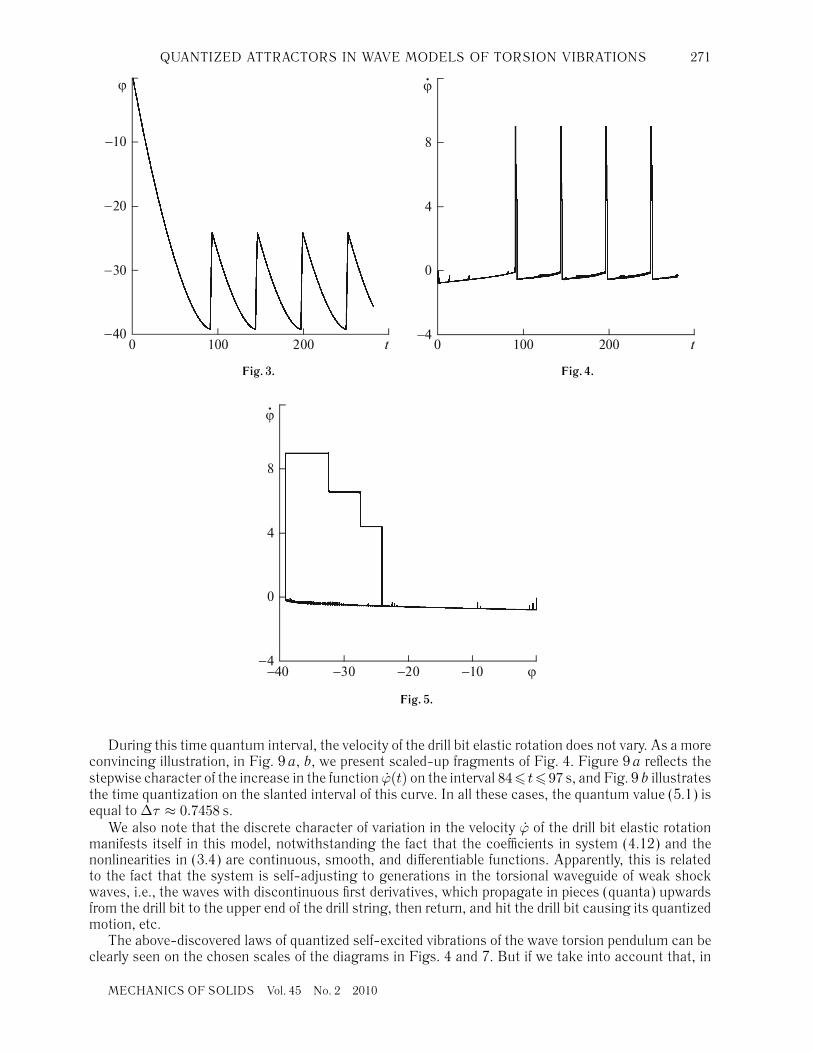
As the parameter ω leaves the range under study through the values ω2 = 3.775 rad/s, a bifurcationof cycle disappearance is realized. The functions ϕ(t) and ϕ(t) and the phase portrait corresponding tothis value of ω are shown in Figs. 6–8, respectively. For ω > ω2, the system again tends to a stablesteady-state equilibrium that is independent of the initial perturbation, and no limit cycles arise there.
Comparing Figs. 3–5 and Figs. 6–8, we can conclude that the qualitative difference between theprocesses of vibration self-excitation for ω1 = 0.712 rad/s and ω2 = 3.775 rad/s is small, and theprocesses occur approximately with the same swing of D ≈ 15 rad, although in this case they havedifferent periods T1 ≈ 53 s and T2 ≈ 9.67 s, respectively.
But the most important common characteristic of these vibrations is the fact that this have a time-quantized character, where the reduced quantity is the string length L and the time quantum Δτ is equalto the time of the twist mode propagation from the drill bit to the drill string top and vice versa:
Δτ =2Lβ
. (5.1)
MECHANICS OF SOLIDS Vol. 45 No. 2 2010
QUANTIZED ATTRACTORS IN WAVE MODELS OF TORSION VIBRATIONS 271
Fig. 3. Fig. 4.
Fig. 5.
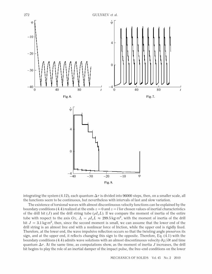
During this time quantum interval, the velocity of the drill bit elastic rotation does not vary. As a moreconvincing illustration, in Fig. 9 a, b, we present scaled-up fragments of Fig. 4. Figure 9 a reflects thestepwise character of the increase in the function ϕ(t) on the interval 84� t�97 s, and Fig. 9 b illustratesthe time quantization on the slanted interval of this curve. In all these cases, the quantum value (5.1) isequal to Δτ ≈ 0.7458 s.
We also note that the discrete character of variation in the velocity ϕ of the drill bit elastic rotationmanifests itself in this model, notwithstanding the fact that the coefficients in system (4.12) and thenonlinearities in (3.4) are continuous, smooth, and differentiable functions. Apparently, this is relatedto the fact that the system is self-adjusting to generations in the torsional waveguide of weak shockwaves, i.e., the waves with discontinuous first derivatives, which propagate in pieces (quanta) upwardsfrom the drill bit to the upper end of the drill string, then return, and hit the drill bit causing its quantizedmotion, etc.
The above-discovered laws of quantized self-excited vibrations of the wave torsion pendulum can beclearly seen on the chosen scales of the diagrams in Figs. 4 and 7. But if we take into account that, in
MECHANICS OF SOLIDS Vol. 45 No. 2 2010
272 GULYAEV et al.
Fig. 6. Fig. 7.
Fig. 8.
integrating the system (4.12), each quantum Δτ is divided into 96000 steps, then, on a smaller scale, allthe functions seem to be continuous, but nevertheless with intervals of fast and slow variation.
The existence of torsional waves with almost discontinuous velocity functions can be explained by theboundary conditions (4.4) realized at the ends z = 0 and z = l for chosen values of inertial characteristicsof the drill bit (J) and the drill string tube (ρIzL). If we compare the moment of inertia of the entiretube with respect to the axis Oz, Jt = ρIzL ≈ 299.5 kg·m2, with the moment of inertia of the drillbit J = 3.1 kg·m2, then, since the second moment is small, we can assume that the lower end of thedrill string is an almost free end with a nonlinear force of friction, while the upper end is rigidly fixed.Therefore, at the lower end, the wave impulsive reflection occurs so that the twisting angle preserves itssign, and at the upper end, it reflects changing this sign to the opposite. Therefore, Eq. (4.1) with theboundary conditions (4.4) admits wave solutions with an almost discontinuous velocity ∂ϕ/∂t and timequantum Δτ . At the same time, as computations show, as the moment of inertia J increases, the drillbit begins to play the role of an inertial damper of the impact pulse, the free-end conditions on the lower
MECHANICS OF SOLIDS Vol. 45 No. 2 2010
QUANTIZED ATTRACTORS IN WAVE MODELS OF TORSION VIBRATIONS 273
Fig. 9.
end do not hold any more, the function of the drill bit angular velocities ceases to be piecewise constant,and the discovered effect of vibration quantization does not manifest itself.
In the cases, where no additional impact is required for a mechanical system to pass from a certaininitial state into the regime of self-excited vibrations, such a passage is called a soft self-excitation. If thevibrations begin spontaneously increase starting only from a certain limit amplitude, then the excitationis said to be hard. For an elastic system to pass to the operation mode of stable hard generation ofvibrations, an initial excitation (pulse) with amplitude greater than a certain critical value is necessary.
Attempts to integrate system (4.12) with initial conditions other than the above-chosen conditionsdo not affect the shapes of limit cycles in any way. This means that the self-excitation is soft. At thesame time, the shape of the attractor is significantly affected by the value of ω. As calculations showed,the vibration period T decreases as ω increases, but since the quantum Δτ remains unchanged in allthe cases, the number of quanta in which a single limit cycle is realized decreases with increasing ω anddecreasing T . In this connection, the shapes of limit cycles become more complicated as ω increases(Fig. 5–8).
To find the dependence of the vibration self-excitation process parameters on the pendulum length,we also consider the case L = 600 m in which the other parameters remain unchanged. The calculationsshowed that, as the length becomes twice as short, the values of the rate of generation and disappearanceof cycles are almost the same and are equal to ω1 = 0.71 s−1 and ω2 = 3.72 s−1, respectively, whilethe values of the vibration periods (T1 ≈ 28.75 s and T2 ≈ 4.87 s) and their swings (D1 ≈ 7.6 radand D2 ≈ 7.5 rad) became approximately halved.
It is of interest to compare the range of frequencies of the drill string self-excited torsion vibrationswith the frequencies of its natural vibrations. Taking into account the fact that the drill bit mass is smallcompared with the mass of the entire drill string, in calculations of its frequencies, we assume that thedrill string is rigidly fixed at the upper end z =L and ϕ(L)=0, while the free end condition ∂ϕ/∂z
∣∣z=0
=0is realized at the lower end z = 0. Then, for the lowest frequency k, the solution of Eq. (4.1) can berepresented in the form
ϕ(z, t) = A sinπ
2L(L − z) · sin kt, k =
πβ
2L.
For the drill string with lengths L = 600 m and L = 1200 m, the values of k and T are equalto k = 8.425 s−1, T = 2π/k = 0.746 s and k = 4.213 s−1, T = 1.492 s. Thus, the drill string self-excitedvibrations occur in the ranges of periods that significantly exceed the periods of their free vibrations.
The above-described properties of the dynamic behavior of wave torsion pendulums were formulatedby considering their generating and disappearing limit cycles. They are also completely confirmed by thelimit cycles constructed inside the ranges ω1 < ω < ω2.
MECHANICS OF SOLIDS Vol. 45 No. 2 2010
274 GULYAEV et al.
It follows from these properties that in the drill strings, as a result of self-excitation, there may arisethe drill bit torsion vibrations, in which the angular velocity function is piecewise constant. This meansthat, in the framework of the above-accepted mathematical model, at the points of discontinuity of thesefunctions, the angular accelerations along with the torques acting on the drill bit take pulse values.Therefore, such regimes of the drill bit self-excited vibrations are significantly dangerous for the dynamicstrength of the system, and they cannot be assumed to be admissible.
CONCLUSIONSIn the present paper, we propose a mathematical model of wave torsion pendulum, which describes
the effects of self-excitation of torsion vibrations of deep-hole drill strings. This model leads to a nonlinearordinary differential equation with a retarded argument. The model was also used to find the followinglaws of self-excitation of torsion vibrations.
There exists a range of variation in the angular velocity of the drill string rotation, where the self-excitation of its periodic torsion vibrations occurs. Outside this range, the drill string is in states ofstable stationary equilibrium.
The process of vibration self-excitation and their shapes are independent of the initial conditions, andtherefore, the self-excitation is soft.
The self-excited vibrations are relaxation oscillations, because they are described by discontinuous(in the framework of the above-accepted wave model) functions of the angular velocity and acceleration.
The self-excited vibrations are time-quantized with the quantum length equal to the time of propa-gation of the twist wave from the drill bit to the drill string top and vice versa.
REFERENCES1. A. W. Iyoho, R. A. Meize, K. K. Millheim, and M. J. Crumrine, “Lessons from Integrated Analysis of GOM
Drilling Performance,” SPE Dril. Comp. 20 (1), 6–16 (2005).2. B. Foster, “‘Network Diagrams’ Improving the Performance of Well-Drilling with Horizontal Displacement
of the Hole Bottom,” Neftegaz. Tekhnol., No. 3, 19–24 (2005).3. P. S. Landa, Self-Excited Oscillations in Systems with Finitely Many Degrees of Freedom (Nauka,
Moscow, 1980) [in Russian].4. M. I. Rabinovich and D. I. Trubetskov, Introduction to the Theory of Vibrations and Waves (Nauka,
Moscow, 1984) [in Russian].5. B. D. Hassard, N. D. Kazarinov, and Y.-H. Wan, Theory and Application of the Hopf Bifurcation
(Cambridge Univ. Press, Cambridge, 1981; Mir, Moscow, 1985).6. N. Challamel, “Rock Destruction Effect on the Stability of a Drilling Structure,” J. Sound Vibr. 233 (2),
235–254 (2000).7. J. Ford Brett, “The Genesis of Torsional Drillstring Vibrations,” SPE Dril. Egngn 7 (3), 168–174 (1992).8. J. D. Jansen and L. Van den Steen, “Active Damping of Self-Excited Torsional Vibrations in Oil Well
Drillstrings,” J. Sound Vibr. 179 (4), 647–668 (1995).9. R. W. Tucker and C. Wang, “On the Effective Control of Torsional Vibrations in Drilling Systems,” J. Sound
Vibr. 224 (1), 101–122 (1999).10. R. W. Tucker and C. Wang, “An Integrated Model for Drill-String Dynamics,” J. Sound Vibr. 224 (1),
123–165 (1999).
MECHANICS OF SOLIDS Vol. 45 No. 2 2010