Embed Size (px)
Citation preview
Office of Research and DevelopmentNational Risk Management Research Laboratory - Water Supply and Water Resources Division
EPA/600/R-11/017 | February 2011 | www.epa.gov /nrmrl
Quality Assurance and Quality Control Practices for Rehabilitation of Sewer and Water Mains
EPA/600/R-11/017
February 2011
Quality Assurance and Quality Control Practices
for
Rehabilitation of Sewer and Water Mains
by
Ed Kampbell
Jason Consultants, LLC
Dec Downey
Jason Consultants, LLC
Wendy Condit, P.E.
Battelle Memorial Institute
Contract No. EP-C-05-057
Task Order No. 58
for
Ariamalar Selvakumar, Ph.D., P.E.
Task Order Manager
U.S. Environmental Protection Agency
National Risk Management Research Laboratory
Water Supply and Water Resources Division
2890 Woodbridge Avenue (MS-104)
Edison, NJ 08837
National Risk Management Research Laboratory
Office of Research and Development
U.S. Environmental Protection Agency
Cincinnati, Ohio 45268

DISCLAIMER
The work reported in this document was funded by the United States Environmental Protection Agency
(EPA) under Task Order (TO) 58 of Contract No. EP-C-05-057 to Battelle. The EPA, through its Office
of Research and Development, funded and managed, or partially funded and collaborated in, the research
described herein. This document has been subjected to the Agency‟s peer and administrative review and
has been approved for publication. Any opinions expressed in this report are those of the author(s) and do
not necessarily reflect the views of the Agency, therefore, no official endorsement should be inferred.
Any mention of trade names or commercial products does not constitute endorsement or recommendation
for use.
iii
EXECUTIVE SUMMARY
As part of the US Environmental Protection Agency (EPA)‟s Aging Water Infrastructure Research
Program, several areas of research are being pursued, including a review of quality assurance and quality
control (QA/QC) practices and acceptance testing during the installation of rehabilitation systems. The
objectives of this research effort were to collect, analyze, and summarize information on the installation
and QA/QC practices for the trenchless rehabilitation of sewer mains and water transmission mains. In
addition, consideration was given to practices related to water service lines, sewer service laterals, force
mains, siphons, sewer manholes, pumping stations, associated wet wells, and other appurtenances. This
review was accomplished primarily by conducting interviews directly with rehabilitation technology
vendors, design engineers, and water and wastewater utilities that have a track record of using trenchless
rehabilitation technologies within their network.
The report provides an overview of how QA/QC issues have been handled in North America for
trenchless rehabilitation technologies. Section 1 provides an overall background on current and historical
practices for inspection and QA/QC of trenchless rehabilitation projects, including definitions of key
terminology. The issues discussed include qualification testing (done to confirm suitability for a
particular application), design considerations for these often proprietary technologies, the impact that the
technologies have on the traditional QA/QC model for engineering projects (i.e., construction observation
roles), and the level of emphasis placed on the QA/QC of the completed works versus more traditional
replacement or new construction techniques.
In Section 2, the various trenchless technologies currently available in North America are introduced and
recommended QA/QC practices are summarized based on consultation with the technology vendors.
Each major type of technology (including those that are relatively new and/or just now emerging) are
discussed from the vendor‟s point of view including the QA/QC criteria that they consider important to
the successful use of their technologies in wastewater collection and water distribution systems.
Section 3 presents QA/QC practices from the perspective of the utilities and/or the owner‟s engineering
representative. In this section, the authors explore not only this perspective from a North American point
of view, but also from a review of how these technologies are treated in the European Union. European
Union standards have been written in a framework that seeks to address the technical requirements of a
particular application. The European Union standards require the individual technologies to be type-
tested for the suitability of the materials in service in that operating environment, to prove the suitability
of their in-situ installation process, and to establish the requisite QA/QC for installers. This inclusive
framework is quite different than the traditional North American model of materials and installation
standards (e.g., American Society for Testing and Materials [ASTM] standards) that tend to be exclusive
to particular technologies. Additionally, the European Union standards set a requirement for continued
installation process verification testing (referred to as audit testing) to maintain the qualification for a
particular technology‟s suitability in an approved application. It would appear from their written
approach that a great deal of emphasis is placed on a quality finished product; although it is known to
often fall short of this ideal in actual practice.
Section 4 addresses the question of how North American utilities use the QA/QC documentation and
other as-built information obtained from their rehabilitation projects to bolster their condition assessment
and asset management activities. Given the demands on their time and shortfalls in budget, it is difficult
for many utilities to adequately carry out QA/QC programs to provide the up-to-date information that is
vital to asset management. Recognizing the value of the as-built information to future system
maintenance, utilities should plan to commit the necessary resources to this effort.
iv
Section 5 summarizes the research findings and discusses gaps or needed improvements that could and/or
should be made to QA/QC steps currently being employed on trenchless rehabilitation projects. The
authors present technology-specific recommendations for best practices to help to ensure that the as-built
improvements are consistent with the engineering design-life calculations.
Good QA/QC practices promote a healthy bid environment and ultimately lead to higher performing
installations of trenchless technologies. Practitioners of a well executed QA/QC program benefit from the
overall lower cost of these improvements and the lower in-house costs of managing these assets over
time. Contractors and technology vendors will respond accordingly to this call for quality once in place.
Better trained construction observers and the proper allocation of their time to monitor the installation
process are key elements of a good QA/QC program. As-built information that is readily available to the
operations engineering team aids in the real-time performance assessment and feedback to the capital
improvements engineering team for the rehabilitation technologies being utilized. Successful QA/QC
programs help to ensure that trenchless technologies will meet their designed service life expectations.
v
FOREWORD
The US Environmental Protection Agency (EPA) is charged by Congress with protecting the Nation‟s
land, air, and water resources. Under a mandate of national environmental laws, the Agency strives to
formulate and implement actions leading to a compatible balance between human activities and the ability
of natural systems to support and nurture life. To meet this mandate, EPA‟s research program is
providing data and technical support for solving environmental problems today and building a science
knowledge base necessary to manage our ecological resources wisely, understand how pollutants affect
our health, and prevent or reduce environmental risks in the future.
The National Risk Management Research Laboratory (NRMRL) is the Agency‟s center for investigation
of technological and management approaches for preventing and reducing risks from pollution that
threaten human health and the environment. The focus of the Laboratory‟s research program is on
methods and their cost-effectiveness for prevention and control of pollution to air, land, water, and sub
surface resources; protection of water quality in public water systems; remediation of contaminated sites,
sediments and ground water; prevention and control of indoor air pollution; and restoration of eco
systems. NRMRL collaborates with both public and private sector partners to foster technologies that
reduce the cost of compliance and to anticipate emerging problems. NRMRL‟s research provides
solutions to environmental problems by: developing and promoting technologies that protect and improve
the environment; advancing scientific and engineering information to support regulatory and policy
decisions; and providing the technical support and information transfer to ensure implementation of
environmental regulations and strategies at the national, state, and community levels.
This publication has been produced as part of the Laboratory‟s strategic long-term research plan. It is
published and made available by EPA‟s Office of Research and Development to assist the user
community and to link researchers with their clients.
Sally Gutierrez, Director
National Risk Management Research Laboratory
vi
ACKNOWLEDGMENTS
This report has been prepared by Jason Consultants with input from the research team, which includes
Battelle and the Trenchless Technology Center (TTC) at Louisiana Tech University. The technical
direction and coordination for this project was provided by Dr. Ariamalar Selvakumar of the Urban
Watershed Management Branch. The project team would like to acknowledge the technology vendors
and utilities that contributed to the review of current QA/QC practices. Sincere appreciation is extended
to their representatives who took the time to provide input and to make valuable contributions to the
report. The authors would like to thank the stakeholder group members (Dr. David Hughes of American
Water and Dr. Walter Graf of Water Environment Research Foundation) for providing written comments.
vii
CONTENTS
DISCLAIMER .............................................................................................................................................iii
EXECUTIVE SUMMARY ......................................................................................................................... iv
FOREWORD ...............................................................................................................................................vi
ACKNOWLEDGEMENT ..........................................................................................................................vii
CONTENTS...............................................................................................................................................viii
FIGURES..................................................................................................................................................... ix
TABLES ...................................................................................................................................................... ix
ACRONYMS AND ABBREVIATIONS ..................................................................................................... x
1.0 INTRODUCTION ................................................................................................................................. 1
1.1 Objectives ................................................................................................................................... 1
1.2 Overview of Inspection and QA/QC for Trenchless Rehabilitation Projects ............................. 1
1.2.1 Qualification Testing for Trenchless Rehabilitation Projects ........................................ 2
1.2.2 QA/QC Procedures for Trenchless Rehabilitation Projects ........................................... 4
1.3 Historical Perspective on Inspection and QA/QC for Trenchless Rehabilitation Projects ......... 5
2.0 QA/QC FROM THE VENDOR‟S PERSPECTIVE .............................................................................. 7
2.1 Technology Vendors Participating in this Study ........................................................................ 7
2.2 QA/QC Practices and Field Inspection Advocated by Vendors ................................................. 8
2.2.1 CIPP QA/QC Practices .................................................................................................. 8
2.2.2 Close-Fit Liner QA/QC Practices ................................................................................ 12
2.2.3 Sprayed-On Coating QA/QC Practices........................................................................ 15
2.2.4 GIPL QA/QC Practices................................................................................................ 17
2.2.5 Pipe Bursting QA/QC Practices................................................................................... 21
3.0 QA/QC FROM THE OWNER‟S PERSPECTIVE .............................................................................. 24
3.1 Utilities Participating in this Study ........................................................................................... 24
3.2 Current QA/QC Practices by Utilities for Trenchless Rehabilitation Projects ......................... 24
3.3 Future Trends in QA Practices by Utilities for Trenchless Rehabilitation Projects.................. 27
3.4 Overview of QA/QC Practices in Europe ................................................................................. 29
3.4.1 QA/QC Practices in Germany...................................................................................... 32
3.4.2 QA/QC Practices in the United Kingdom.................................................................... 35
3.4.3 QA/QC Practices in France.......................................................................................... 36
3.4.4 QA/QC Practices in Denmark...................................................................................... 36
4.0 QA/QC DATA COLLECTION AND ASSET MANAGEMENT ...................................................... 37
4.1 Quantity and Quality of As-Built Data Collected ..................................................................... 38
4.2 Use of As-Built Information in Utility Asset Management Programs...................................... 40
4.3 Desired Use of As-Built Information and Potential Benefits from Its Collection .................... 44
5.0 RECOMMENDATIONS FOR IMPROVING QA/QC PRACTICES................................................. 45
5.1 Technology Specific Recommendations for QA/QC Best Practices ........................................ 45
5.1.1 CIPP Best Practices Recommendations....................................................................... 45
5.1.2 Close Fit Liner Systems Best Practices Recommendations ......................................... 46
5.1.3 Sprayed-on Polymeric Coating Best Practices Recommendations .............................. 47
5.1.4 GIPL Best Practices Recommendations ...................................................................... 48
5.1.5 Pipe Bursting Best Practices Recommendations ......................................................... 50
5.2 Encouraging and Achieving the Owner‟s Implementation of Best Practice Methodologies.... 51
6.0 REFERENCES .................................................................................................................................... 54
viii
FIGURES
Figure 1-1. Example of a Long-Term Structural Performance Test of a CIPP Resin Material ................ 3
Figure 2-1. Inversion Set-Up .................................................................................................................. 11
Figure 2-2. CIPP Inversion in Progress .................................................................................................. 11
Figure 2-3. Finished CIPP Showing a Tight Fit ..................................................................................... 11
Figure 2-4. FnF Liners Before and After Expansion .............................................................................. 12
Figure 2-5. HDPE FnF Being Inserted in a Pipeline .............................................................................. 13
Figure 2-6. PVC FnF Material Heated and Being Pulled into Position .................................................. 13
Figure 2-7. Winching Liner in Place....................................................................................................... 13
Figure 2-8. Outlet Control Station .......................................................................................................... 14
Figure 2-9. Post Installation CCTV Inspection....................................................................................... 14
Figure 2-10. Spray-Applied Polyurethane in a Man-Entry Size Pipe....................................................... 16
Figure 2-11. Strip Style GIPL................................................................................................................... 18
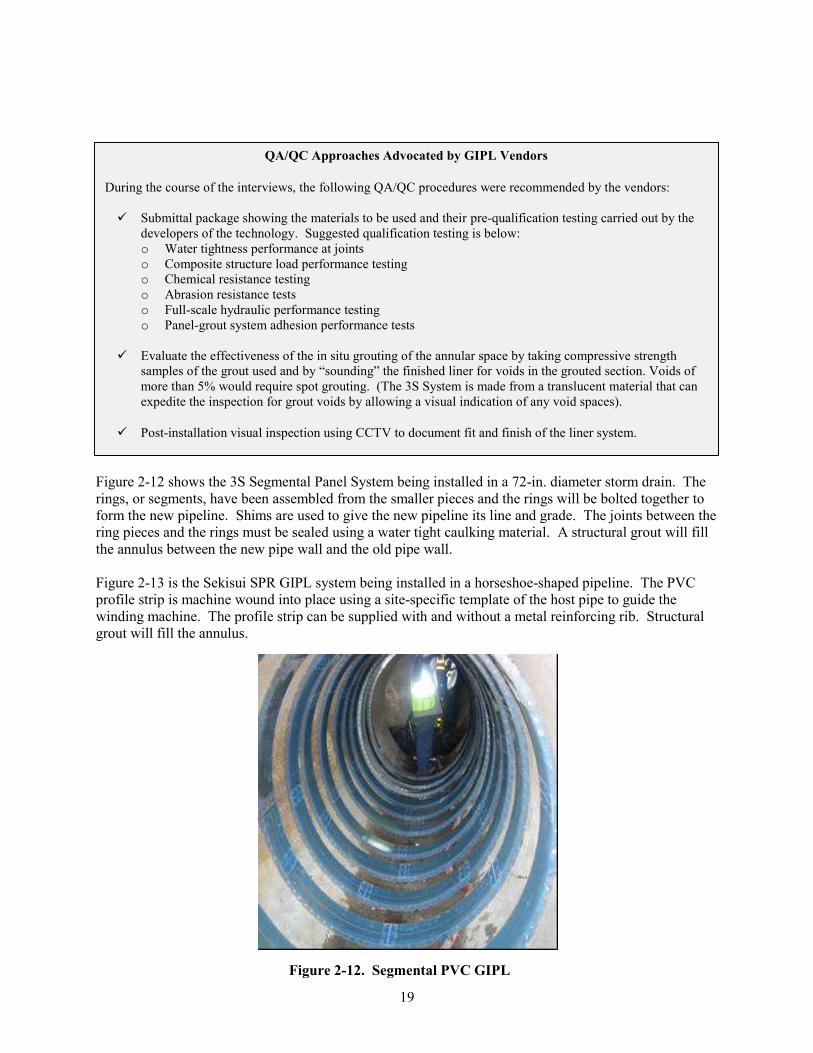
Figure 2-12. Segmental PVC GIPL .......................................................................................................... 19
Figure 2-13. Machine Wound in Place Liner System............................................................................... 19
Figure 2-14. Grouting Operation Setup .................................................................................................... 20
Figure 2-15. Visual of Grout Filling Operation ........................................................................................ 20
Figure 2-16. GIPL Composite Cross-Section ........................................................................................... 20
Figure 2-17. Typical Pipe Bursting Setup................................................................................................. 23
Figure 2-18. Pipe Splitting Tool ............................................................................................................... 23
Figure 3-1. Format of the Renovation Standards.................................................................................... 31
Figure 4-1. Field Sample Test Report..................................................................................................... 38
Figure 4-2. Ultrasonic Thickness Gage .................................................................................................. 39
Figure 4-3. Pipeline Location Probe ....................................................................................................... 40
TABLES
Table 2-1. Summary of Rehabilitation Technology Vendor Study Participation ........................................ 7
Table 3-1. Summary of European Standards for Trenchless Rehabilitation Technologies ....................... 30
Table 3-2. Example of QA/QC Tests Performed by IKT on CIPP Liners (IKT, 2008)............................. 33
ix
AASHTO
ANSI
American Association of State Highway and Transportation Officials
American National Standards Institute
ASCE
ASTM
ATV
AWWA
American Society of Civil Engineers
American Society for Testing and Materials
Abwassertechnische Vereinigung (German Wastewater Technical Association)
American Water Works Association
CCTV Closed-Circuit Television
CEN
CESWI
CIPP
COFRAC
CSO
Comité Européen de Normalisation (European Committee for Standardization)
Civil Engineering Specification for the Water Industry (UK)
Cured-In-Place Pipe
Comité Francais d'Accréditation (French Committee for Certification)
Combined Sewer Overflow
CSTB
CUPPS
Centre Scientifique et Technique du Bâtiment (Scientific and Technical Centre for
Building)
Check-Up Program for Small Systems
DIBt
DIN
DoE
DOSD
DSC
DVWK
DWA
Deutches Institut für Bautechnik (German Institute for Civil Engineering)
Deutsches Institut für Normung (German Institute for Standardization)
Department of the Environment (UK)
Division of Sewerage and Drainage
Differential Scanning Calorimetry
Deutscher Verband für Wasserwirtschaft und Kulturbau (German Association for Water
and Land)
Deutsche Vereinigung für Wasserwirtschaft, Abwasser und Abfall e.V. (German
Association for Water, Wastewater, and Waste)
EPA
ETV
Environmental Protection Agency
Environmental Testing and Verification
FnF Fold-and-Form
GIPL Grout-In-Place Liner
GIS Geographic Information System
HDD
HDPE
Horizontal Directional Drilling
High Density Polyethylene
IGN
I/I
IKT
IPBA
ISO
Information and Guidance Notes (UK)
Infiltration and Inflow
Institut für Unterirdische Infrastruktur (Institute for Underground Infrastructure)
International Pipe Bursting Association
International Organization for Standardization
LRWU Little Rock Wastewater Utility
MG Million Gallons
MSDS Material Safety Data Sheet
ACRONYMS AND ABBREVIATIONS
x
NACE National Association of Corrosion Engineers
NASSCO National Association of Sewer Service Companies
NASTT North American Society for Trenchless Technology
NRMRL National Risk Management Research Laboratory
NSF National Sanitary Foundation
NWC National Water Council (UK)
NWIS National Water Information System
PACP Pipeline Assessment and Certification Program
PE Polyethylene
psi Pounds per Square Inch
PWS Performance Work Statement
PVC Polyvinyl Chloride
QA Quality Assurance
QC Quality Control
RAL Reichsausschuss für Lieferbedingungen (RAL) (National Board of Supply Conditions)
RFP Request for Proposal
SDR Standard Dimension Ratio
SRM Sewer Rehabilitation Manual (UK)
TAG-R Trenchless Assessment Guide – Rehabilitation
TDS Technical Data Sheet
TTC Trenchless Technology Center
UK United Kingdom
USGS United States Geological Survey
UV Ultraviolet
WICS Water Industry Certification Scheme (UK)
WIS Water Industry Specifications (UK)
WRc Water Research Centre (UK)
xi
1.0 INTRODUCTION
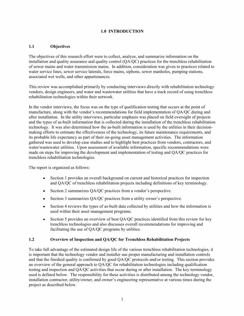
1.1 Objectives
The objectives of this research effort were to collect, analyze, and summarize information on the
installation and quality assurance and quality control (QA/QC) practices for the trenchless rehabilitation
of sewer mains and water transmission mains. In addition, consideration was given to practices related to
water service lines, sewer service laterals, force mains, siphons, sewer manholes, pumping stations,
associated wet wells, and other appurtenances.
This review was accomplished primarily by conducting interviews directly with rehabilitation technology
vendors, design engineers, and water and wastewater utilities that have a track record of using trenchless
rehabilitation technologies within their network.
In the vendor interviews, the focus was on the type of qualification testing that occurs at the point of
manufacture, along with the vendor‟s recommendations for field implementation of QA/QC during and
after installation. In the utility interviews, particular emphasis was placed on field oversight of projects
and the types of as-built information that is collected during the installation of the trenchless rehabilitation
technology. It was also determined how the as-built information is used by the utilities in their decision-
making efforts to estimate the effectiveness of the technology, its future maintenance requirements, and
its probable life expectancy as part of their on-going asset management activities. The information
gathered was used to develop case studies and to highlight best practices from vendors, contractors, and
water/wastewater utilities. Upon assessment of available information, specific recommendations were
made on steps for improving the development and implementation of testing and QA/QC practices for
trenchless rehabilitation technologies.
The report is organized as follows:
Section 1 provides an overall background on current and historical practices for inspection
and QA/QC of trenchless rehabilitation projects including definitions of key terminology.
Section 2 summarizes QA/QC practices from a vendor‟s perspective.
Section 3 summarizes QA/QC practices from a utility owner‟s perspective.
Section 4 reviews the types of as-built data collected by utilities and how the information is
used within their asset management programs.
Section 5 provides an overview of best QA/QC practices identified from this review for key
trenchless technologies and also discusses overall recommendations for improving and
facilitating the use of QA/QC programs by utilities.
Overview of Inspection and QA/QC for Trenchless Rehabilitation Projects
To take full advantage of the estimated design life of the various trenchless rehabilitation technologies, it
is important that the technology vendor and installer use proper manufacturing and installation controls
and that the finished quality is confirmed by good QA/QC protocols and/or testing. This section provides
an overview of the general approach to QA/QC for rehabilitation technologies including qualification
testing and inspection and QA/QC activities that occur during or after installation. The key terminology
used is defined below. The responsibility for these activities is distributed among the technology vendor,
installation contractor, utility/owner, and owner‟s engineering representative at various times during the
project as described below.
1
1.2
Key Definitions for QA/QC Programs
Qualification testing is defined as a series of tests on the materials and/or related installation process to determine
the suitability of a given technology for use in a particular application. Some owners require pre-qualification or
certification of the vendor‟s equipment and materials prior to use at their utility.
Quality control is a system of routine technical activities to measure and control the quality of the product as it is
being produced and/or installed. The QC system is designed to:
1. Provide routine and consistent checks to ensure data integrity, correctness, and process completeness;
2. Identify and address errors and omissions in the installation process; and
3. Document and archive product installations and record all QC activities.
QC activities include general methods such as accuracy checks on the data acquisition and calculations and the
use of approved standardized procedures for making processing measurements, addressing uncertainties in the
installation process, archiving the installation process information, and reporting.
Quality assurance activities include a planned system of review procedures conducted by personnel not directly
involved in the product‟s installation process. Reviews, preferably by independent third parties, should be
performed upon the final product following the implementation of the QC procedures. Reviews verify that the
quality objectives were met, ensure that the total installed product is as required, and support the effectiveness of
the QC program being used in the manufacturing and installation process.
Acceptance testing confirms that the installation is consistent with the product that was pre-qualified in the
design phase and that it should live up to its design performance expectations.
1.2.1 Qualification Testing for Trenchless Rehabilitation Projects. Qualification (also referred
to as type testing) is typically the responsibility of the technology vendor in North America. Qualification
testing is performed on the materials and the related installation process to determine the suitability of a
given technology for use in a particular application. The design approach must be supported by the
technology‟s qualification testing to withstand the rigors of the proposed installation process and function
long-term in the environment in which it is being used. As discussed in Section 2, the type of
qualification testing required varies according to the rehabilitation technology vendor. For example,
some manufactured products must meet consensus qualification testing requirements in published
industry standards such as the American Society of Testing and Materials (ASTM), while other
technologies meet proprietary specifications established by the vendor for material and installation
requirements. The latter is typical for a new product that falls outside the range of existing products in
general use. Examples of types of qualification testing include creep testing, hydrostatic or pressure
design basis testing, chemical resistance testing, strain corrosion testing, and other material property
testing requirements. Ideally, such testing is conducted using samples that are as closely representative of
the installed products as possible.
Creep testing is used by the industry to define the long-term performance properties of the materials (e.g.,
polyvinyl chloride [PVC], polyethylene [PE], thermoset resins, etc.) used in the various technologies.
Creep is defined as the time-dependent part of strain resulting from constant stress. The ASTM D2990
method is widely accepted for creep testing and is used to determine the tensile, compressive, and/or
flexural creep-rupture properties of the materials. ASTM D2837 and D2992 are widely used to qualify
2
the internal hydrostatic or pressure design basis for pipelines made from these materials. Utilizing
laboratory prepared plate and/or pipe specimens, the materials are loaded to produce strength-regression
curves that allow for the material‟s long-term performance to be extrapolated from the 10,000 hours of
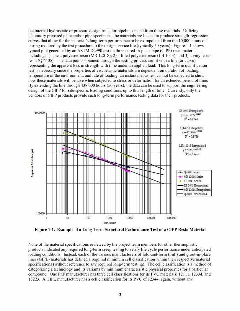
testing required by the test procedure to the design service life (typically 50 years). Figure 1-1 shows a
typical plot generated by an ASTM D2990 test on three cured-in-place pipe (CIPP) resin materials
including: 1) a neat polyester resin (MR 12018); 2) a filled polyester resin (LB 1043); and 3) a vinyl ester
resin (Q 6405). The data points obtained through the testing process are fit with a line (or curve)
representing the apparent loss in strength with time under an applied load. This long-term qualification
test is necessary since the properties of viscoelastic materials are dependent on duration of loading,
temperature of the environment, and rate of loading; an instantaneous test cannot be expected to show
how these materials will behave when subjected to stress or deformation for an extended period of time.
By extending the line through 438,000 hours (50 years), the data can be used to support the engineering
design of the CIPP for site-specific loading conditions up to this length of time. Currently, only the
vendors of CIPP products provide such long-term performance testing data for their products.
Figure 1-1. Example of a Long-Term Structural Performance Test of a CIPP Resin Material
None of the material specifications reviewed by the project team members for other thermoplastic
products indicated any required long-term creep testing to verify life cycle performance under anticipated
loading conditions. Instead, each of the various manufacturers of fold-and-form (FnF) and grout-in-place
liner (GIPL) materials has defined a required minimum cell classification within their respective material
specifications (without reference to any required long-term testing). The cell classification is a method of
categorizing a technology and its variants by minimum characteristic physical properties for a particular
compound. One FnF manufacturer has three cell classifications for its PVC materials: 12111, 12334, and
13223. A GIPL manufacturer has a cell classification for its PVC of 12344, again, without any
3
requirement for long-term creep testing to qualify this minimum cell class as to its long-term acceptability
in service. To design a thermoplastic pipe for long-term performance under a persistent load, the
regressed, long-term strength is used. However, for a thermoplastic pipeline under constant external
pressure, this compressive load causes plastic creep over the long-term that will result in the wall
thickness actually increasing and thus increasing the virtual strength of the liner (Gumbel, 1998). Still,
one would like to see the testing done in such a manner as to predict when, or if, buckling may occur
when subjected to a long-term loading situation, as there are known instances of these failures having
occurred in the field.
Chemical resistance testing is essential to ensure that the materials will survive and perform in their
anticipated operating environment, especially for sanitary sewers. Again, the amount of testing that is
done to this end varies among the various technologies. CIPP‟s material specification, ASTM D5813,
requires that plate samples be made and immersed in seven chemical solutions that define the
approximate range of exposure to corrosive environmental conditions that might be encountered in
sanitary sewers. The duration of testing in these solutions is for a period of one year; samples must retain
at least 80% of their initial physical properties. Pipe samples also must be strain corrosion tested using a
1.0 N solution of sulfuric acid for a period of 10,000 hours; all of the samples must pass. No chemical
resistance testing requirements were cited in the ASTM standards for the FnF PVC materials, the spiral
wound PVC products, the PVC or high density polyethylene (HDPE) GIPL products, or the HDPE
deformed-reformed products. Further, the cell classifications listed previously do not spell out the
chemical resistance performance of the compounds used to meet those designations. However, the
thermoplastic materials covered in this study have been tested for chemical resistance via the 112-day
pickle jar test as outlined in the Greenbook: Standard Specifications for Public Works Construction (Joint
Cooperative Committee of the Southern California Chapter, 2009).
Rehabilitation products including spray applied and cured-in-place materials must be tested for their
suitability for use in drinking water applications. This is accomplished under the National Sanitary
Foundation (NSF) Standard 61 for Drinking Water System Components, which is the health effects
standard for all devices, components, and materials to ensure that these products do not contribute
contaminants to drinking water that could cause adverse health effects.
More details on qualification testing requirements specific to CIPP, close-fit liner, sprayed-on coatings,
GIPL, and pipe bursting are provided in Section 2.
1.2.2 QA/QC Procedures for Trenchless Rehabilitation Projects. Once the trenchless
construction products are qualified as to their materials and method of installation, a good system of
QA/QC procedures is necessary to ensure that the as-built product meets the performance of the qualified
product.
QC procedures for the various trenchless technologies discussed in this report are typically given to the
utility and/or the project engineer and installation contractor by the technology manufacturer or vendor.
The installation process is given control limits by the technology vendor that allow the installer to pre
judge the finished quality of the installation during the execution of the work and prior to acceptance
testing by the utility owner. To further reinforce the commitment to having a quality installation,
manufacturers can also develop a technology-specific ASTM installation standard for their system.
Section 2 provides examples of the current extent of coverage of industry-wide standards for the various
rehabilitation systems available.
QA and acceptance testing confirm that the installation is consistent with the product that was pre-
qualified in the design phase and that it should live up to its design performance expectations. QA is the
responsibility of the utility/owner and/or their designated engineering representative. Whether utilizing
4
1.3
prescriptive or performance specifications, it is important that the type of QA testing to be performed is
communicated with the installer and that the contract documents require follow through on this testing in
the field. At times, trenchless technologies have specifications for prudent QA testing, but those
overseeing the project do not perform the testing stated therein. Samples of the finished installation need
to be taken to confirm that the minimum mechanical properties have been achieved or have gone
unaltered from the rigors of the installation process. Fit and finish should be evaluated in light of the
prior condition of the host pipe and the rehabilitation system being installed. It is generally preferable
that the contractual relationship with the testing laboratory for any QA testing is between the owner and
the laboratory and not the installation contractor and the laboratory (Kampbell and Whittle, 2003).
Specifications come in two basic formats: prescriptive-based or performance-based as described below.
Prescriptive specifications contain detailed information on the materials to be used and the methods to be
followed for their installation. For example, a concrete structure for a particular application would have
the reinforcing steel defined in terms of the mechanical properties of the steel, the sizes of the rebar to be
used and its location in the proposed structural component. Additionally, the 5,000 psi concrete used
would have its mix defined (weight of aggregate, sand, cement, and water), detailed instructions on its
placement in the structure (calls for vibration, maximum drop, etc), and provisions for how it is to be
cured (provisions for cold temperatures, etc.). The project engineer in a prescriptive-based specification
is essentially “in charge” of the work.
Using a performance-based specification, the performance requirements for the structure would be
conveyed to the contractor and it would be the contractor‟s responsibility to design the component, lay
out the materials required to achieve that design, and execute the work of correctly constructing the
designed component. The owner or their representative would simply observe that the work is completed
per the contractor‟s submittals and confirm the quality of the installation by testing to determine whether
or not the required final performance requirements were met. Performance-based specifications may also
include prescriptive remedies for specific deficiencies observed upon final inspection.
Prescriptive specifications require the owner or project engineer to be well trained in the details of the
work to be done. In a performance-based environment, the responsibility for the detailed design and
specifications lies primarily with the contractor and/or technology vendor. When it comes to emerging
and evolving technologies, such as trenchless rehabilitation of pipelines, performance specifications are
currently the more prudent choice.
Historical Perspective on Inspection and QA/QC for Trenchless Rehabilitation Projects
The trenchless rehabilitation technology industry continues to evolve, but two factors have significantly
influenced the limited adoption of QA/QC practices over time. The first factor is that rehabilitation
technologies were treated as “repair” approaches in the past with less rigorous design, installation, and
QA/QC practices. The second factor is the proprietary nature of new and emerging rehabilitation
technologies.
In the past, trenchless technologies have been treated as relatively easy-to-use solutions to piping system
repair and/or reconstruction needs. This resulted in projects being accomplished with a set of contract
documents consisting of one or more plan sheets showing the identity of the reaches to be rehabilitated,
their physical location, and the technology vendor‟s suggested technical specification. The determination
of the design parameters were either defined in very conservative terms or left to the contractor to
determine, essentially requiring much of the work to be “designed” by the installation contractor and/or
technology vendor. Installation observation on these types of projects was intermittent at best and there
was little or no prior training given to the inspector to prepare them for ensuring a quality installation.
5
Most project specifications are currently written in a prescriptive format. Thus, the contractor is only
obliged to meet the required installation procedures, physical property tests, closed circuit television
(CCTV) inspection of the rehabilitated pipe, and the work is routinely accepted.
Another influencing factor to QA/QC is the proprietary nature of some rehabilitation technologies. As the
governing patents expire on many aspects of these rehabilitation technologies, more companies are
encouraged to enter the marketplace and compete with the established technology providers. This
provides increased competition – leading in general to lower prices – but it also may provide an incentive
to cut corners on QC as part of the new price competition. New entrants into the rehabilitation
marketplace may not have as well a developed technical “know how” (staff education level and
experience). This means that systems that have already gone through their learning curve and become
highly reliable techniques may exhibit a more variable performance as the marketplace widens to the non-
developers of the technology.
As use of these technologies widen, it is important that standardized QA/QC procedures are in place and
used effectively - both to provide for a high performance and long-lasting product and also to allow
contractors who provide quality to compete fairly in the marketplace. Currently, there are only a few
standards available to facilitate a more uniform approach to pipeline rehabilitation, especially for drinking
water applications. For example, there are only two American Water Works Association (AWWA)
standards available for the rehabilitation process including AWWA C602 Cement-Mortar Lining of Water
Pipelines in Place and AWWA C620 Spray-Applied In-Place Epoxy Lining of Water Pipelines.
In summary, better QA/QC-related procedures are an important part of providing improved rehabilitation
technologies for wastewater collection and water distribution systems, especially as the governing patents
expire and proprietary systems become non-proprietary or commodity products.
6
2.1
2.0 QA/QC FROM THE VENDOR’S PERSPECTIVE
Most trenchless rehabilitation methods are the result of proprietary ideas, which have developed into
proprietary systems. As such, the standards for their design and use have been developed on a technique
by-technique basis. Many technical innovations evolve in this way with the design, construction, and
several aspects of QA/QC being provided exclusively by the company offering the technology. The
downside to this approach is the lack of control over the design details by the owners and their
consultants. Over time, these proprietary technologies will make a transition from this situation into one
where most aspects of the design process are handled by the design engineer working on behalf of the
owner. However, this transition period can take many years to occur. For example, CIPP has been more
widely available for the past 14 years, but is still in the transitional period in terms of design and QA/QC
practices.
Technology Vendors Participating in this Study
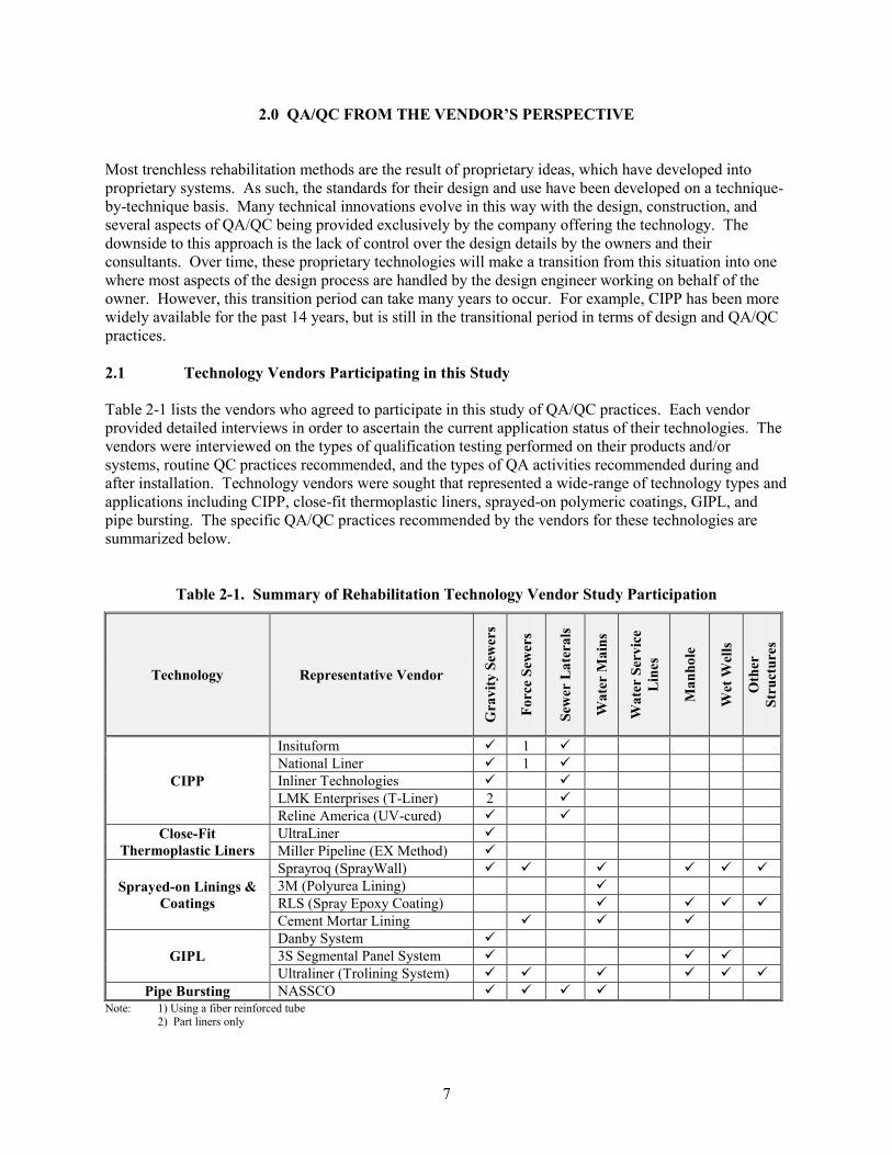
Table 2-1 lists the vendors who agreed to participate in this study of QA/QC practices. Each vendor
provided detailed interviews in order to ascertain the current application status of their technologies. The
vendors were interviewed on the types of qualification testing performed on their products and/or
systems, routine QC practices recommended, and the types of QA activities recommended during and
after installation. Technology vendors were sought that represented a wide-range of technology types and
applications including CIPP, close-fit thermoplastic liners, sprayed-on polymeric coatings, GIPL, and
pipe bursting. The specific QA/QC practices recommended by the vendors for these technologies are
summarized below.
Table 2-1. Summary of Rehabilitation Technology Vendor Study Participation
Technology Representative Vendor
Gra
vit
y S
ewer
s
Fo
rce
Sew
ers
Sew
er L
ate
ra
ls
Wa
ter
Ma
ins
Wa
ter
Ser
vic
e
Lin
es
Ma
nh
ole
Wet
Wel
ls
Oth
er
Str
uct
ure
s
Insituform 1
National Liner 1
CIPP Inliner Technologies
LMK Enterprises (T-Liner) 2
Reline America (UV-cured)
Close-Fit UltraLiner
Thermoplastic Liners Miller Pipeline (EX Method)
Sprayroq (SprayWall)
Sprayed-on Linings & 3M (Polyurea Lining)
Coatings RLS (Spray Epoxy Coating)
Cement Mortar Lining
Danby System
GIPL 3S Segmental Panel System
Ultraliner (Trolining System)
Pipe Bursting NASSCO
Note: 1) Using a fiber reinforced tube
2) Part liners only
7
2.2 QA/QC Practices and Field Inspection Advocated by Vendors
During the course of interviews with the technology vendors, they were asked to address their
recommendations for QA/QC practices. Qualification of the materials to be used by a particular
technology and the installation process that must be used in its placement is vendor driven for the most
part with these relatively new and developing technologies. As discussed below, CIPP has reached a
point along its developmental curve where a general materials qualification test has been developed; but
none of the recent ultraviolet (UV) light cured entries have undergone this generic qualifications testing.
Life cycle or long-term performance testing is crucial to qualify a particular technology. Service life
claims must be supported by adequate qualification testing. This section summarizes the information
received from the vendor interviews, along with a summary of the relevant industry standards for each
type of technology.
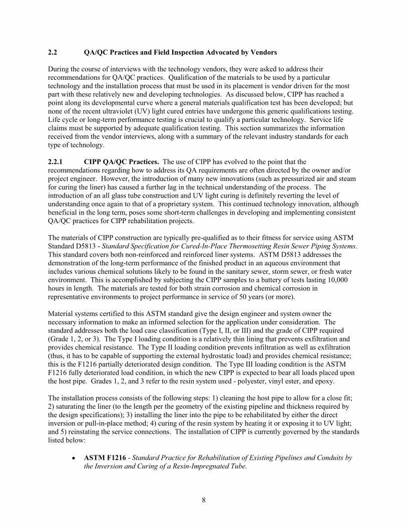
2.2.1 CIPP QA/QC Practices. The use of CIPP has evolved to the point that the
recommendations regarding how to address its QA requirements are often directed by the owner and/or
project engineer. However, the introduction of many new innovations (such as pressurized air and steam
for curing the liner) has caused a further lag in the technical understanding of the process. The
introduction of an all glass tube construction and UV light curing is definitely reverting the level of
understanding once again to that of a proprietary system. This continued technology innovation, although
beneficial in the long term, poses some short-term challenges in developing and implementing consistent
QA/QC practices for CIPP rehabilitation projects.
The materials of CIPP construction are typically pre-qualified as to their fitness for service using ASTM
Standard D5813 - Standard Specification for Cured-In-Place Thermosetting Resin Sewer Piping Systems.
This standard covers both non-reinforced and reinforced liner systems. ASTM D5813 addresses the
demonstration of the long-term performance of the finished product in an aqueous environment that
includes various chemical solutions likely to be found in the sanitary sewer, storm sewer, or fresh water
environment. This is accomplished by subjecting the CIPP samples to a battery of tests lasting 10,000
hours in length. The materials are tested for both strain corrosion and chemical corrosion in
representative environments to project performance in service of 50 years (or more).
Material systems certified to this ASTM standard give the design engineer and system owner the
necessary information to make an informed selection for the application under consideration. The
standard addresses both the load case classification (Type I, II, or III) and the grade of CIPP required
(Grade 1, 2, or 3). The Type I loading condition is a relatively thin lining that prevents exfiltration and
provides chemical resistance. The Type II loading condition prevents infiltration as well as exfiltration
(thus, it has to be capable of supporting the external hydrostatic load) and provides chemical resistance;
this is the F1216 partially deteriorated design condition. The Type III loading condition is the ASTM
F1216 fully deteriorated load condition, in which the new CIPP is expected to bear all loads placed upon
the host pipe. Grades 1, 2, and 3 refer to the resin system used - polyester, vinyl ester, and epoxy.
The installation process consists of the following steps: 1) cleaning the host pipe to allow for a close fit;
2) saturating the liner (to the length per the geometry of the existing pipeline and thickness required by
the design specifications); 3) installing the liner into the pipe to be rehabilitated by either the direct
inversion or pull-in-place method; 4) curing of the resin system by heating it or exposing it to UV light;
and 5) reinstating the service connections. The installation of CIPP is currently governed by the standards
listed below:
ASTM F1216 - Standard Practice for Rehabilitation of Existing Pipelines and Conduits by
the Inversion and Curing of a Resin-Impregnated Tube.
8
ASTM F1743 - Standard Practice for Rehabilitation of Existing Pipelines and Conduits by
Pulled-in-Place Installation of Cured-in-Place Thermosetting Resin Pipe.
ASTM F2019 - Standard Practice for Rehabilitation of Existing Pipelines and Conduits by
the Pulled-in-Place Installation of Glass Reinforced Plastic (GRP) Cured-in-Place
Thermosetting Resin Pipe.
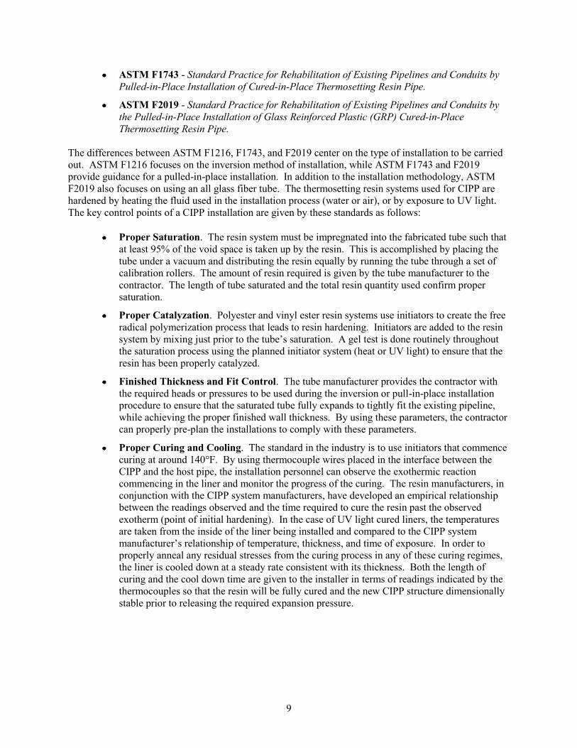
The differences between ASTM F1216, F1743, and F2019 center on the type of installation to be carried
out. ASTM F1216 focuses on the inversion method of installation, while ASTM F1743 and F2019
provide guidance for a pulled-in-place installation. In addition to the installation methodology, ASTM
F2019 also focuses on using an all glass fiber tube. The thermosetting resin systems used for CIPP are
hardened by heating the fluid used in the installation process (water or air), or by exposure to UV light.
The key control points of a CIPP installation are given by these standards as follows:
Proper Saturation. The resin system must be impregnated into the fabricated tube such that
at least 95% of the void space is taken up by the resin. This is accomplished by placing the
tube under a vacuum and distributing the resin equally by running the tube through a set of
calibration rollers. The amount of resin required is given by the tube manufacturer to the
contractor. The length of tube saturated and the total resin quantity used confirm proper
saturation.
Proper Catalyzation. Polyester and vinyl ester resin systems use initiators to create the free
radical polymerization process that leads to resin hardening. Initiators are added to the resin
system by mixing just prior to the tube‟s saturation. A gel test is done routinely throughout
the saturation process using the planned initiator system (heat or UV light) to ensure that the
resin has been properly catalyzed.
Finished Thickness and Fit Control. The tube manufacturer provides the contractor with
the required heads or pressures to be used during the inversion or pull-in-place installation
procedure to ensure that the saturated tube fully expands to tightly fit the existing pipeline,
while achieving the proper finished wall thickness. By using these parameters, the contractor
can properly pre-plan the installations to comply with these parameters.
Proper Curing and Cooling. The standard in the industry is to use initiators that commence
curing at around 140°F. By using thermocouple wires placed in the interface between the
CIPP and the host pipe, the installation personnel can observe the exothermic reaction
commencing in the liner and monitor the progress of the curing. The resin manufacturers, in
conjunction with the CIPP system manufacturers, have developed an empirical relationship
between the readings observed and the time required to cure the resin past the observed
exotherm (point of initial hardening). In the case of UV light cured liners, the temperatures
are taken from the inside of the liner being installed and compared to the CIPP system
manufacturer‟s relationship of temperature, thickness, and time of exposure. In order to
properly anneal any residual stresses from the curing process in any of these curing regimes,
the liner is cooled down at a steady rate consistent with its thickness. Both the length of
curing and the cool down time are given to the installer in terms of readings indicated by the
thermocouples so that the resin will be fully cured and the new CIPP structure dimensionally
stable prior to releasing the required expansion pressure.
9
During the course of interviews with the technology vendors as part of this study, the following QA/QC
practices were advocated by CIPP vendors (see text box).
QA/QC Approach Advocated by CIPP Vendors
During the course of the interviews, the following QA/QC procedures were recommended by the vendors:
Submittal documents detailing the material pre-qualification testing that has been accomplished
o Resin or resin-tube long-term strength performance using ASTM D2990
o Chemical corrosion performance per ASTM D5813, Sections 6.4.1 and 6.4.3
o Strain corrosion performance per ASTM D5813, Sections 6.4.2 and 6.4.3
In situ sampling either by restrained tube or flat plate to verify the finished CIPP structural properties.
(Note: this was not recommended for the UV light cure systems due to a cited conflict of the
installation equipment with the area in which the sampling would have to take place.)
o Sample type
Restrained for pipe diameters up to 18-in.
Flat plate for pipe diameters greater than 18-in.
o Structural properties to be measured from sample
Restrained tube
Thickness
Flexural modulus of elasticity
Tensile strength (if application requires internal pressure performance)
Flat Plate Sample
Flexural modulus of elasticity
Tensile strength (if application requires internal pressure performance)
In situ thickness by the restrained tube or ultrasonic testing of the liner in the host pipeline
o Restrained tube per ASTM D5813, Section 8.1.2 using ASTM D3567
o In situ by ultrasonic gage using ASTM E797 methodology, Section 6.1.2
Post-installation CCTV inspection to confirm the liner‟s close fit and interior finish
o Verify tight fit at ends and any opened lateral connections
o Verify CIPP is not leaking through the wall at any location
o Verify that CIPP has no lifts or reversals of curvature
o Verify that CIPP has a uniform appearance with no “dry spots”
o Verify any fins or wrinkles are within industry standards and acceptable for this application
o Verify re-instated lateral openings are fully open and smooth; no resin slug in lateral opening
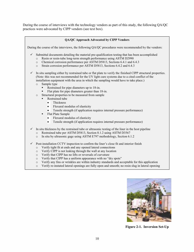
Figure 2-1. Inversion Set-Up
10
11
Figure 2-1 shows a typical direct inversion installation of CIPP using a column of water. The height of
the platform is selected by consideration of the tube‟s required minimum installation pressure to properly
expand tightly inside the existing pipeline and the amount of head estimated to propel the inversion of the
tube for the length being installed. These heads have been empirically derived by the tube manufacturers
and are given to the installation contractor. Failure to maintain the minimum inversion pressure at the
nose of the advancing tube can result in longitudinal finning of the CIPP inner-most layer, which is the
interior surface of the new pipeline. Failure to account for the required head to propel the inversion
(overcoming the frictional resistance of this process) can also result in the liner stopping and refusing to
complete the inversion process.
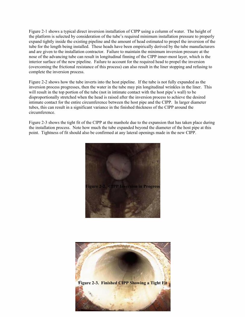
Figure 2-2 shows how the tube inverts into the host pipeline. If the tube is not fully expanded as the
inversion process progresses, then the water in the tube may pin longitudinal wrinkles in the liner. This
will result in the top portion of the tube (not in intimate contact with the host pipe‟s wall) to be
disproportionally stretched when the head is raised after the inversion process to achieve the desired
intimate contact for the entire circumference between the host pipe and the CIPP. In larger diameter
tubes, this can result in a significant variance in the finished thickness of the CIPP around the
circumference.
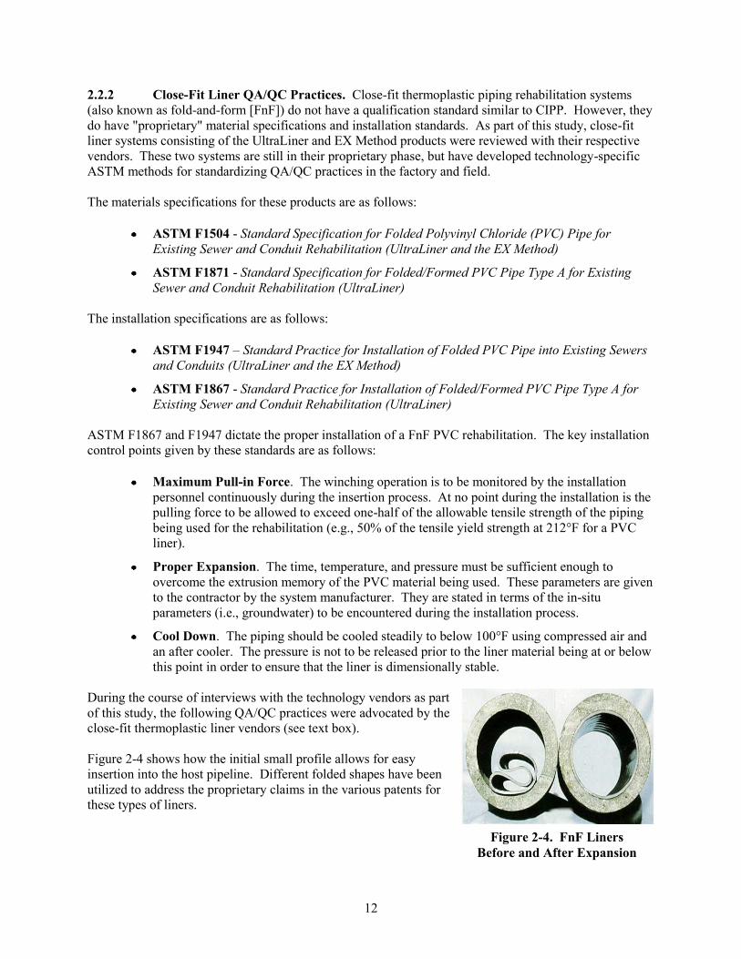
Figure 2-3 shows the tight fit of the CIPP at the manhole due to the expansion that has taken place during
the installation process. Note how much the tube expanded beyond the diameter of the host pipe at this
point. Tightness of fit should also be confirmed at any lateral openings made in the new CIPP.
Figure 2-2. CIPP Inversion in Progress
Figure 2-3. Finished CIPP Showing a Tight Fit
2.2.2 Close-Fit Liner QA/QC Practices. Close-fit thermoplastic piping rehabilitation systems
(also known as fold-and-form [FnF]) do not have a qualification standard similar to CIPP. However, they
do have "proprietary" material specifications and installation standards. As part of this study, close-fit
liner systems consisting of the UltraLiner and EX Method products were reviewed with their respective
vendors. These two systems are still in their proprietary phase, but have developed technology-specific
ASTM methods for standardizing QA/QC practices in the factory and field.
The materials specifications for these products are as follows:
ASTM F1504 - Standard Specification for Folded Polyvinyl Chloride (PVC) Pipe for
Existing Sewer and Conduit Rehabilitation (UltraLiner and the EX Method)
ASTM F1871 - Standard Specification for Folded/Formed PVC Pipe Type A for Existing
Sewer and Conduit Rehabilitation (UltraLiner)
The installation specifications are as follows:
ASTM F1947 – Standard Practice for Installation of Folded PVC Pipe into Existing Sewers
and Conduits (UltraLiner and the EX Method)
ASTM F1867 - Standard Practice for Installation of Folded/Formed PVC Pipe Type A for
Existing Sewer and Conduit Rehabilitation (UltraLiner)
ASTM F1867 and F1947 dictate the proper installation of a FnF PVC rehabilitation. The key installation
control points given by these standards are as follows:
Maximum Pull-in Force. The winching operation is to be monitored by the installation
personnel continuously during the insertion process. At no point during the installation is the
pulling force to be allowed to exceed one-half of the allowable tensile strength of the piping
being used for the rehabilitation (e.g., 50% of the tensile yield strength at 212°F for a PVC
liner).
Proper Expansion. The time, temperature, and pressure must be sufficient enough to
overcome the extrusion memory of the PVC material being used. These parameters are given
to the contractor by the system manufacturer. They are stated in terms of the in-situ
parameters (i.e., groundwater) to be encountered during the installation process.
Cool Down. The piping should be cooled steadily to below 100°F using compressed air and
an after cooler. The pressure is not to be released prior to the liner material being at or below
this point in order to ensure that the liner is dimensionally stable.
During the course of interviews with the technology vendors as part
of this study, the following QA/QC practices were advocated by the
close-fit thermoplastic liner vendors (see text box).
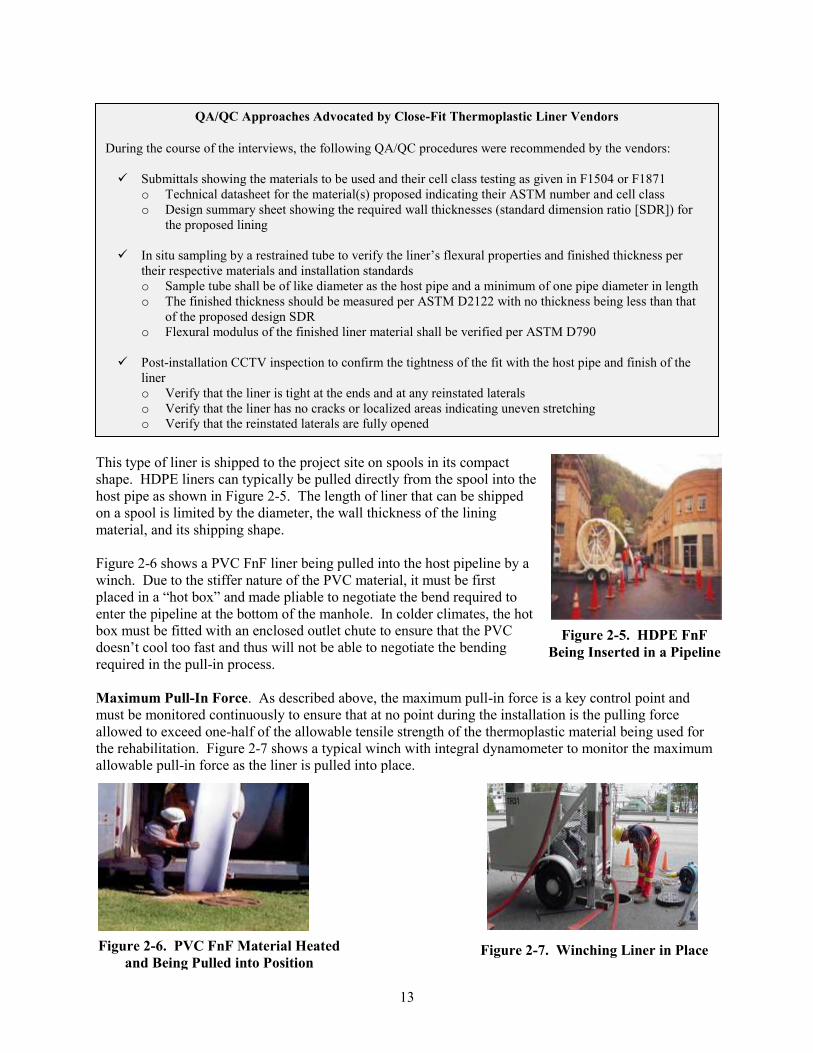
Figure 2-4 shows how the initial small profile allows for easy
insertion into the host pipeline. Different folded shapes have been
utilized to address the proprietary claims in the various patents for
these types of liners.
Figure 2-4. FnF Liners
Before and After Expansion
12
QA/QC Approaches Advocated by Close-Fit Thermoplastic Liner Vendors
During the course of the interviews, the following QA/QC procedures were recommended by the vendors:
Submittals showing the materials to be used and their cell class testing as given in F1504 or F1871
o Technical datasheet for the material(s) proposed indicating their ASTM number and cell class
o Design summary sheet showing the required wall thicknesses (standard dimension ratio [SDR]) for
the proposed lining
In situ sampling by a restrained tube to verify the liner‟s flexural properties and finished thickness per
their respective materials and installation standards
o Sample tube shall be of like diameter as the host pipe and a minimum of one pipe diameter in length
o The finished thickness should be measured per ASTM D2122 with no thickness being less than that
of the proposed design SDR
o Flexural modulus of the finished liner material shall be verified per ASTM D790
Post-installation CCTV inspection to confirm the tightness of the fit with the host pipe and finish of the
liner
o Verify that the liner is tight at the ends and at any reinstated laterals
o Verify that the liner has no cracks or localized areas indicating uneven stretching
o Verify that the reinstated laterals are fully opened
This type of liner is shipped to the project site on spools in its compact
shape. HDPE liners can typically be pulled directly from the spool into the
host pipe as shown in Figure 2-5. The length of liner that can be shipped
on a spool is limited by the diameter, the wall thickness of the lining
material, and its shipping shape.
Figure 2-6 shows a PVC FnF liner being pulled into the host pipeline by a
winch. Due to the stiffer nature of the PVC material, it must be first
placed in a “hot box” and made pliable to negotiate the bend required to
enter the pipeline at the bottom of the manhole. In colder climates, the hot
box must be fitted with an enclosed outlet chute to ensure that the PVC
doesn‟t cool too fast and thus will not be able to negotiate the bending
required in the pull-in process.
Maximum Pull-In Force. As described above, the maximum pull-in force is a key control point and
must be monitored continuously to ensure that at no point during the installation is the pulling force
allowed to exceed one-half of the allowable tensile strength of the thermoplastic material being used for
the rehabilitation. Figure 2-7 shows a typical winch with integral dynamometer to monitor the maximum
allowable pull-in force as the liner is pulled into place.
Figure 2-5. HDPE FnF
Being Inserted in a Pipeline
Figure 2-6. PVC FnF Material Heated
and Being Pulled into Position Figure 2-7. Winching Liner in Place
13
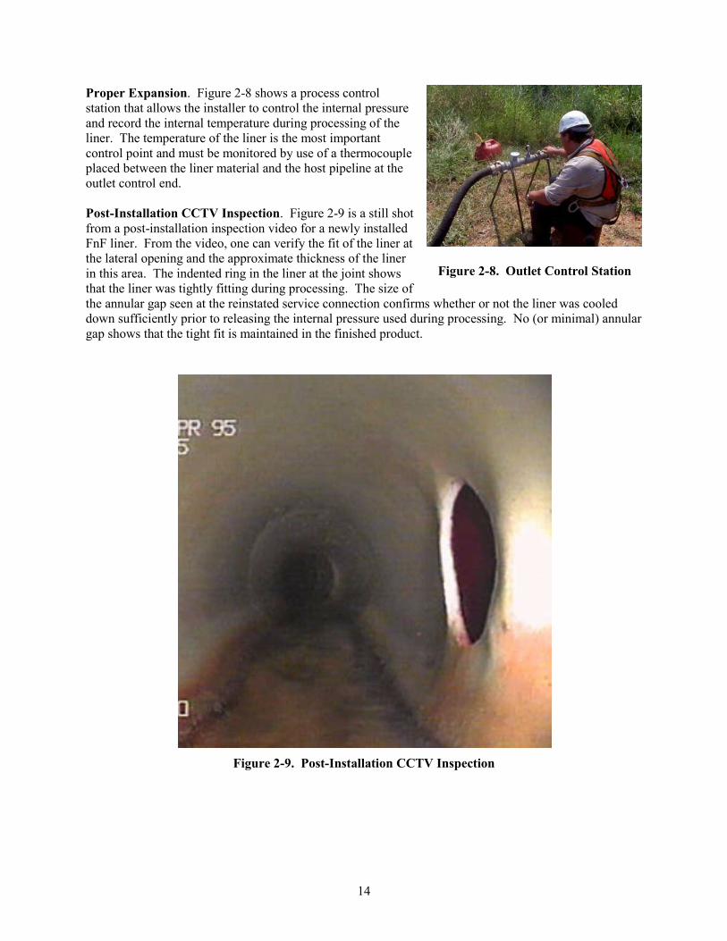
Proper Expansion. Figure 2-8 shows a process control
station that allows the installer to control the internal pressure
and record the internal temperature during processing of the
liner. The temperature of the liner is the most important
control point and must be monitored by use of a thermocouple
placed between the liner material and the host pipeline at the
outlet control end.
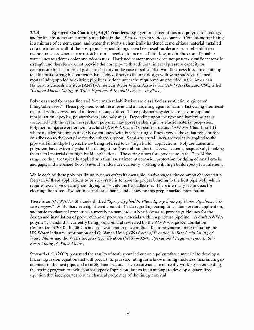
Post-Installation CCTV Inspection. Figure 2-9 is a still shot
from a post-installation inspection video for a newly installed
FnF liner. From the video, one can verify the fit of the liner at
the lateral opening and the approximate thickness of the liner
in this area. The indented ring in the liner at the joint shows Figure 2-8. Outlet Control Station
that the liner was tightly fitting during processing. The size of
the annular gap seen at the reinstated service connection confirms whether or not the liner was cooled
down sufficiently prior to releasing the internal pressure used during processing. No (or minimal) annular
gap shows that the tight fit is maintained in the finished product.
Figure 2-9. Post-Installation CCTV Inspection
14
2.2.3 Sprayed-On Coating QA/QC Practices. Sprayed-on cementitious and polymeric coatings
and/or liner systems are currently available in the US market from various sources. Cement-mortar lining
is a mixture of cement, sand, and water that forms a chemically hardened cementitious material installed
onto the interior wall of the host pipe. Cement linings have been used for decades as a rehabilitation
method in cases where a corrosion barrier is needed, to increase fluid flow, and in the case of potable
water lines to address color and odor issues. Hardened cement mortar does not possess significant tensile
strength and therefore cannot provide the host pipe with additional internal pressure capacity or
compensate for lost internal pressure capacity in the case of substantial wall thickness loss. In an attempt
to add tensile strength, contractors have added fibers to the mix design with some success. Cement
mortar lining applied to existing pipelines is done under the requirements provided in the American
National Standards Institute (ANSI)/American Water Works Association (AWWA) standard C602 titled
“Cement Mortar Lining of Water Pipelines 4-In. and Larger – In Place.”
Polymers used for water line and force main rehabilitation are classified as synthetic “engineered
lining/adhesives.” These polymers combine a resin and a hardening agent to form a fast curing thermoset
material with a cross-linked molecular composition. Three polymeric systems are used in pipeline
rehabilitation: epoxies, polyurethanes, and polyureas. Depending upon the type and hardening agent
combined with the resin, the resultant polymer may posses either rigid or elastic material properties.
Polymer linings are either non-structural (AWWA Class I) or semi-structural (AWWA Class II or III)
where a differentiation is made between liners with inherent ring stiffness versus those that rely entirely
on adhesion to the host pipe for their shape support. Semi-structural liners are typically applied to the
pipe wall in multiple layers, hence being referred to as “high build” applications. Polyurethanes and
polyureas have extremely short hardening times (several minutes to several seconds, respectively) making
them ideal materials for high build applications. The curing times for epoxies are in the 7 to 14 day
range, so they are typically applied as a thin layer aimed at corrosion protection, bridging of small cracks
and gaps, and increased flow. Several vendors are currently working with high build epoxy formulations.
While each of these polymer lining systems offers its own unique advantages, the common characteristic
for each of these applications to be successful is to have the proper bonding to the host pipe wall, which
requires extensive cleaning and drying to provide the best adhesion. There are many techniques for
cleaning the inside of water lines and force mains and achieving this proper surface preparation.
There is an AWWA/ANSI standard titled “Spray-Applied In-Place Epoxy Lining of Water Pipelines, 3 In.
and Larger.” While there is a significant amount of data regarding curing times, temperature application,
and basic mechanical properties, currently no standards in North America provide guidelines for the
design and installation of polyurethane or polyurea materials within a pressure pipeline. A draft AWWA
polymeric standard is currently being prepared and reviewed by the AWWA Pipe Rehabilitation
Committee in 2010. In 2007, standards were put in place in the UK for polymeric lining including the
UK Water Industry Information and Guidance Note (IGN) Code of Practice: In Situ Resin Lining of
Water Mains and the Water Industry Specification (WIS) 4-02-01 Operational Requirements: In Situ
Resin Lining of Water Mains.
Steward et al. (2009) presented the results of testing carried out on a polyurethane material to develop a
linear regression equation that will predict the pressure rating for a known lining thickness, maximum gap
diameter in the host pipe, and a safety factor value. The researchers are currently working on expanding
the testing program to include other types of spray-on linings in an attempt to develop a generalized
equation that incorporates key mechanical properties of the lining material.
15
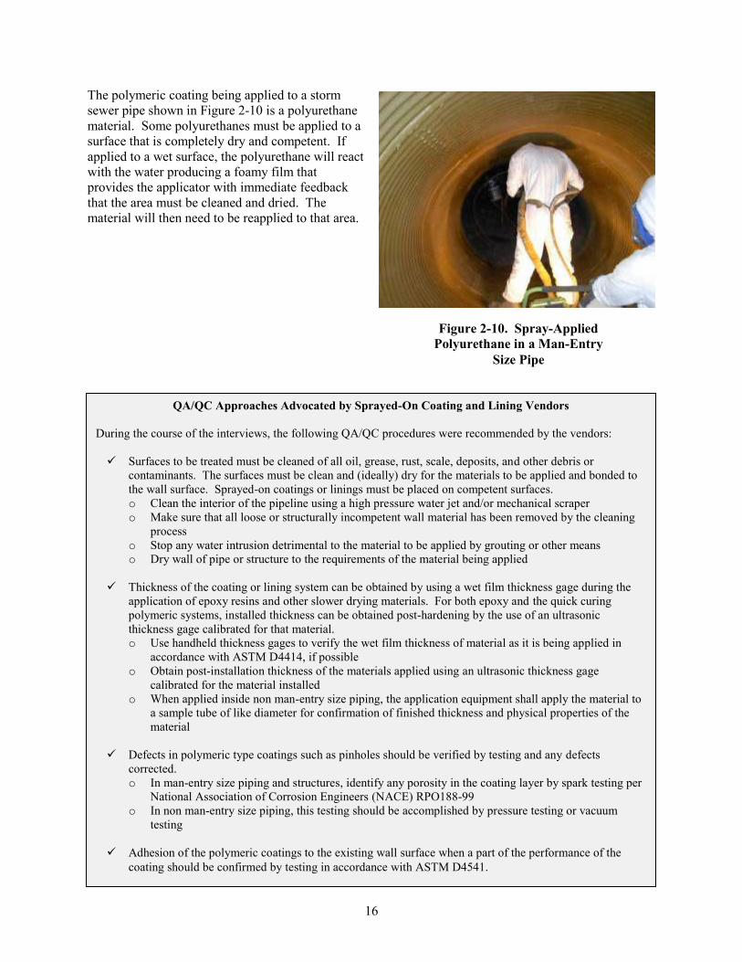
The polymeric coating being applied to a storm
sewer pipe shown in Figure 2-10 is a polyurethane
material. Some polyurethanes must be applied to a
surface that is completely dry and competent. If
applied to a wet surface, the polyurethane will react
with the water producing a foamy film that
provides the applicator with immediate feedback
that the area must be cleaned and dried. The
material will then need to be reapplied to that area.
Figure 2-10. Spray-Applied
Polyurethane in a Man-Entry
Size Pipe
QA/QC Approaches Advocated by Sprayed-On Coating and Lining Vendors
During the course of the interviews, the following QA/QC procedures were recommended by the vendors:
Surfaces to be treated must be cleaned of all oil, grease, rust, scale, deposits, and other debris or
contaminants. The surfaces must be clean and (ideally) dry for the materials to be applied and bonded to
the wall surface. Sprayed-on coatings or linings must be placed on competent surfaces.
o Clean the interior of the pipeline using a high pressure water jet and/or mechanical scraper
o Make sure that all loose or structurally incompetent wall material has been removed by the cleaning
process
o Stop any water intrusion detrimental to the material to be applied by grouting or other means
o Dry wall of pipe or structure to the requirements of the material being applied
Thickness of the coating or lining system can be obtained by using a wet film thickness gage during the
application of epoxy resins and other slower drying materials. For both epoxy and the quick curing
polymeric systems, installed thickness can be obtained post-hardening by the use of an ultrasonic
thickness gage calibrated for that material.
o Use handheld thickness gages to verify the wet film thickness of material as it is being applied in
accordance with ASTM D4414, if possible
o Obtain post-installation thickness of the materials applied using an ultrasonic thickness gage
calibrated for the material installed
o When applied inside non man-entry size piping, the application equipment shall apply the material to
a sample tube of like diameter for confirmation of finished thickness and physical properties of the
material
Defects in polymeric type coatings such as pinholes should be verified by testing and any defects
corrected.
o In man-entry size piping and structures, identify any porosity in the coating layer by spark testing per
National Association of Corrosion Engineers (NACE) RPO188-99
o In non man-entry size piping, this testing should be accomplished by pressure testing or vacuum
testing
Adhesion of the polymeric coatings to the existing wall surface when a part of the performance of the
coating should be confirmed by testing in accordance with ASTM D4541.
16
2.2.4 GIPL QA/QC Practices. GIPL has typically been used in pipes ranging with diameters
from 10 to 78 in. However, it is currently beginning to see much more use in larger diameter piping (48
to 120 in.). These systems place a relatively thin thermoplastic material that has been extruded with a
stiffening profile tightly inside an existing pipeline. The placement is either by machine winding into
place or by hand placement. The resulting annular space between the host pipe and the liner material
must be filled with a cementitious grout material to form a new composite structure (lining/grout/host
pipe) that will be able to withstand the anticipated external loading. As part of this study, GIPL systems
reviewed by the project team were the Danby System, the Sekisui-SPR, the 3S Segmental Panel System,
and Trolining.
The materials specifications for these products are as follows:
ASTM F1735 – Standard Specification for Poly (Vinyl Chloride) (PVC) Profile Strip for
PVC Liners for Rehabilitation of Existing Man-Entry Sewers and Conduits.
ASTM F1697 – Standard Specification for Poly (Vinyl Chloride) (PVC) Profile Strip for
Machine Spiral-Wound Pipe Liner Rehabilitation of Existing Sewers and Conduit.
The installation specifications are as follows:
ASTM F1698 - Standard Practice for Installation of PVC Profile Strip Liner and
Cementitious Grout for Rehabilitation of Existing Man-Entry Sewers and Conduits
ASTM F1741 - Standard Practice for Installation of Machine Spiral Wound PVC Liner Pipe
for Rehabilitation of Existing Sewers and Conduits
The key control points of the installation process are as follows:
Thermoplastic Material Placement. The strips or panel sections are assembled in the host
pipeline to the design inner diameter. Depending on the design thickness of the grout layer,
shims are employed to properly position the assembled liner within the host pipeline.
Shimming also serves to provide proper alignment and grade of the lining placement. These
are checked prior to commencing grouting.
Grout Placement. Grout placement is absolutely crucial to the quality of the finished
installation. With the exception of the 3S Panel System, the installer is blinded by either the
opaque nature of these panels or the procedure used for the grouting process. Trolining fills
the lining with water to confirm complete filling is taking place. To that end, the installer is
advised to make holes in the lining to confirm that grout has reached a certain level in the
annulus. The 3S Panel System uses a translucent panel to provide the installer with a real-
time indicator of the grouting operation‟s quality.
The Danby System has been available in the US market for some time, while the Sekisui SPR, the 3S
Segmental Panel System, and the Trolining System are just starting to make their appearance in North
America. Only the Danby System currently has an ASTM materials standard (F1735). The Danby
System and the 3S System are made exclusively of PVC materials. The Trolining System is
manufactured in HDPE. Sekisui SPR is made of PVC or HDPE and meets or exceeds the requirements in
ASTM F1697 for the PVC product. The Danby System has an ASTM installation specification under
F1698 as listed above. Trolining‟s representatives are currently working with the ASTM Committee
F17.67 to develop a set of specifications for their product. Representatives of the 3S System have not yet
advanced to that point in the market entry process.
17
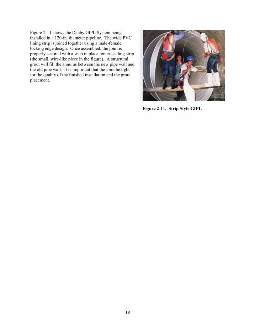
Figure 2-11 shows the Danby GIPL System being
installed in a 120-in. diameter pipeline. The wide PVC
lining strip is joined together using a male-female
locking edge design. Once assembled, the joint is
properly secured with a snap in place joiner-sealing strip
(the small, wire-like piece in the figure). A structural
grout will fill the annulus between the new pipe wall and
the old pipe wall. It is important that the joint be tight
for the quality of the finished installation and the grout
placement.
Figure 2-11. Strip Style GIPL
18
QA/QC Approaches Advocated by GIPL Vendors
During the course of the interviews, the following QA/QC procedures were recommended by the vendors:
Submittal package showing the materials to be used and their pre-qualification testing carried out by the
developers of the technology. Suggested qualification testing is below:
o Water tightness performance at joints
o Composite structure load performance testing
o Chemical resistance testing
o Abrasion resistance tests
o Full-scale hydraulic performance testing
o Panel-grout system adhesion performance tests
Evaluate the effectiveness of the in situ grouting of the annular space by taking compressive strength
samples of the grout used and by “sounding” the finished liner for voids in the grouted section. Voids of
more than 5% would require spot grouting. (The 3S System is made from a translucent material that can
expedite the inspection for grout voids by allowing a visual indication of any void spaces).
Post-installation visual inspection using CCTV to document fit and finish of the liner system.
Figure 2-12 shows the 3S Segmental Panel System being installed in a 72-in. diameter storm drain. The
rings, or segments, have been assembled from the smaller pieces and the rings will be bolted together to
form the new pipeline. Shims are used to give the new pipeline its line and grade. The joints between the
ring pieces and the rings must be sealed using a water tight caulking material. A structural grout will fill
the annulus between the new pipe wall and the old pipe wall.
Figure 2-13 is the Sekisui SPR GIPL system being installed in a horseshoe-shaped pipeline. The PVC
profile strip is machine wound into place using a site-specific template of the host pipe to guide the
winding machine. The profile strip can be supplied with and without a metal reinforcing rib. Structural
grout will fill the annulus.
Figure 2-12. Segmental PVC GIPL
19
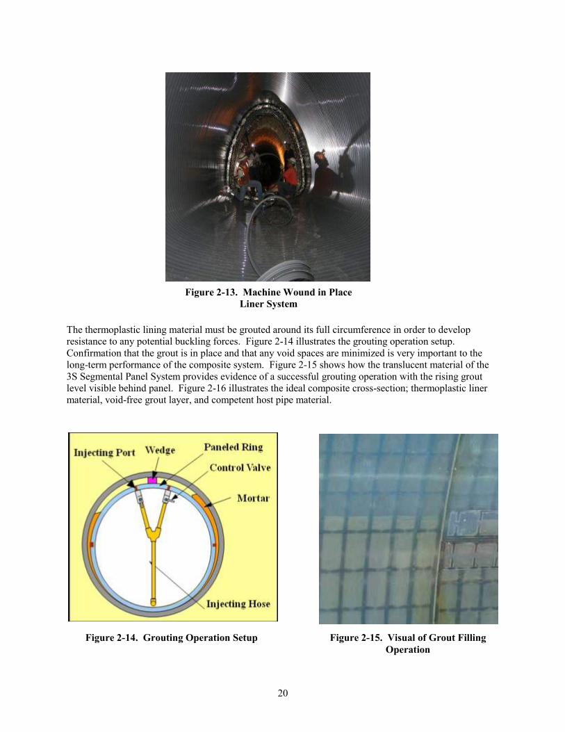
Figure 2-13. Machine Wound in Place
Liner System
The thermoplastic lining material must be grouted around its full circumference in order to develop
resistance to any potential buckling forces. Figure 2-14 illustrates the grouting operation setup.
Confirmation that the grout is in place and that any void spaces are minimized is very important to the
long-term performance of the composite system. Figure 2-15 shows how the translucent material of the
3S Segmental Panel System provides evidence of a successful grouting operation with the rising grout
level visible behind panel. Figure 2-16 illustrates the ideal composite cross-section; thermoplastic liner
material, void-free grout layer, and competent host pipe material.
Figure 2-14. Grouting Operation Setup Figure 2-15. Visual of Grout Filling
Operation
20
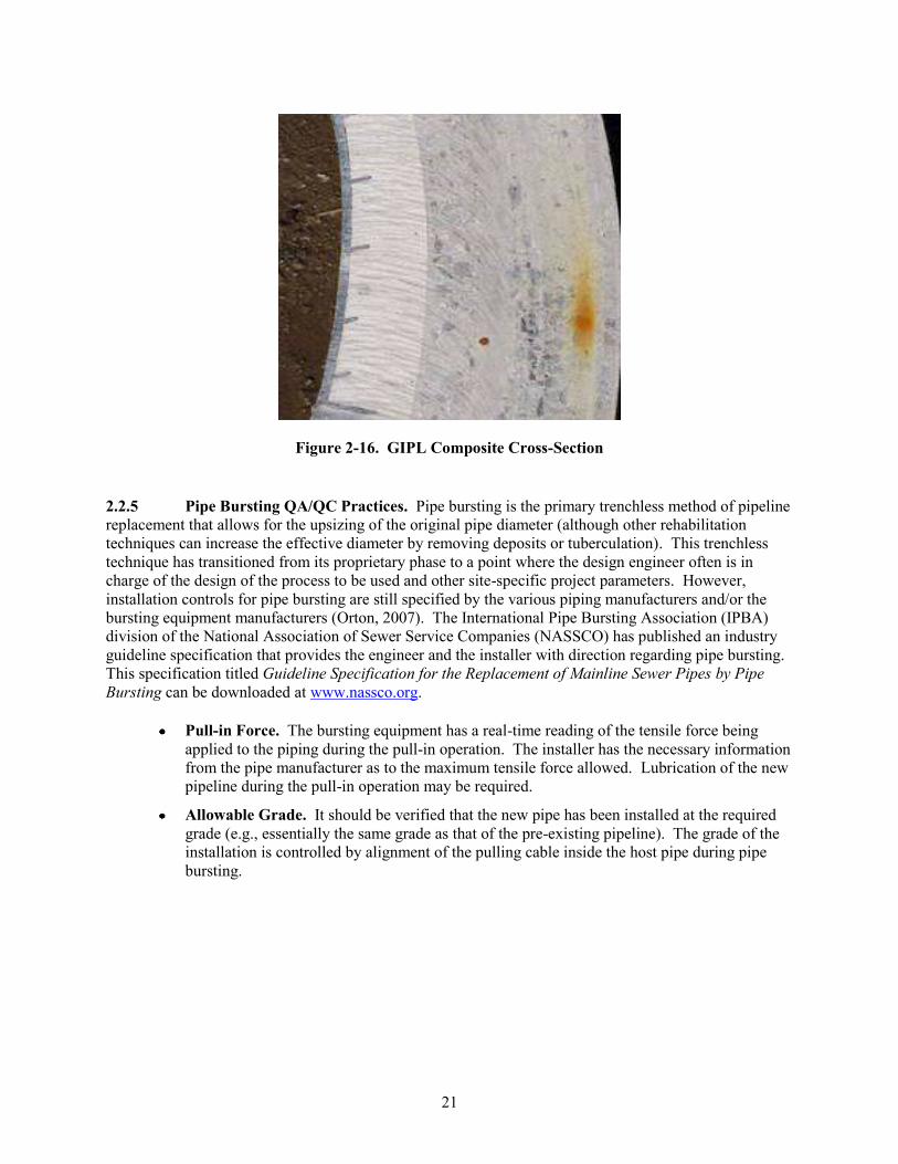
Figure 2-16. GIPL Composite Cross-Section
2.2.5 Pipe Bursting QA/QC Practices. Pipe bursting is the primary trenchless method of pipeline
replacement that allows for the upsizing of the original pipe diameter (although other rehabilitation
techniques can increase the effective diameter by removing deposits or tuberculation). This trenchless
technique has transitioned from its proprietary phase to a point where the design engineer often is in
charge of the design of the process to be used and other site-specific project parameters. However,
installation controls for pipe bursting are still specified by the various piping manufacturers and/or the
bursting equipment manufacturers (Orton, 2007). The International Pipe Bursting Association (IPBA)
division of the National Association of Sewer Service Companies (NASSCO) has published an industry
guideline specification that provides the engineer and the installer with direction regarding pipe bursting.
This specification titled Guideline Specification for the Replacement of Mainline Sewer Pipes by Pipe
Bursting can be downloaded at www.nassco.org.
Pull-in Force. The bursting equipment has a real-time reading of the tensile force being
applied to the piping during the pull-in operation. The installer has the necessary information
from the pipe manufacturer as to the maximum tensile force allowed. Lubrication of the new
pipeline during the pull-in operation may be required.
Allowable Grade. It should be verified that the new pipe has been installed at the required
grade (e.g., essentially the same grade as that of the pre-existing pipeline). The grade of the
installation is controlled by alignment of the pulling cable inside the host pipe during pipe
bursting.
21
QA/QC Approaches Advocated by the Pipe Bursting Industry
Given the widespread use of pipe bursting, the project team reviewed the guideline published by NASSCO for
recommendations on QA/QC approaches for pipe bursting as follows:
Submittals
o Certifications of training by the pipe bursting systems manufacturer
o Certification of training by the piping material manufacturer
o Certification of training by the fusion equipment manufacturer
o Detailed construction procedures and sequence of construction
o Locations, sizes, and construction methods of the service reconnection pits
o Methods of construction, reconnection, and restoration of existing service laterals
o Detailed descriptions of the methods of modifying existing manholes
o Detailed procedures for the installation and bedding of the new pipe in the launching and receiving
pits
o Sewer bypass pumping plans
o Method and disposal of host pipe material (if required)
o Materials submittals
Construction observation
o Inspect the condition of the new pipe subsequent to the bursting operation to confirm structural
integrity has not been compromised
o Evaluate the ground surface for any settlement or heaving
o Observe the fusion process to ensure that proper joining of pipe lengths is occurring
A post-installation CCTV inspection shall be carried out to confirm the as-built condition of the new
pipeline.
22
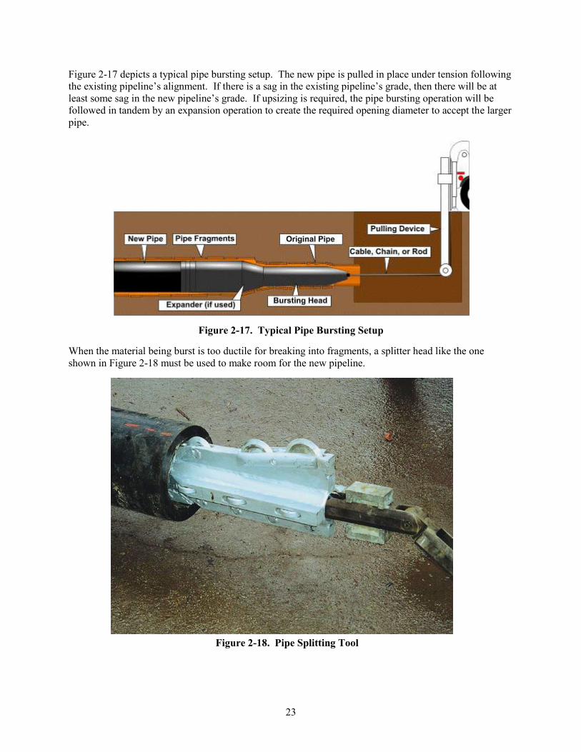
Figure 2-18. Pipe Splitting Tool
Figure 2-17 depicts a typical pipe bursting setup. The new pipe is pulled in place under tension following
the existing pipeline‟s alignment. If there is a sag in the existing pipeline‟s grade, then there will be at
least some sag in the new pipeline‟s grade. If upsizing is required, the pipe bursting operation will be
followed in tandem by an expansion operation to create the required opening diameter to accept the larger
pipe.
Figure 2-17. Typical Pipe Bursting Setup
When the material being burst is too ductile for breaking into fragments, a splitter head like the one
shown in Figure 2-18 must be used to make room for the new pipeline.
23
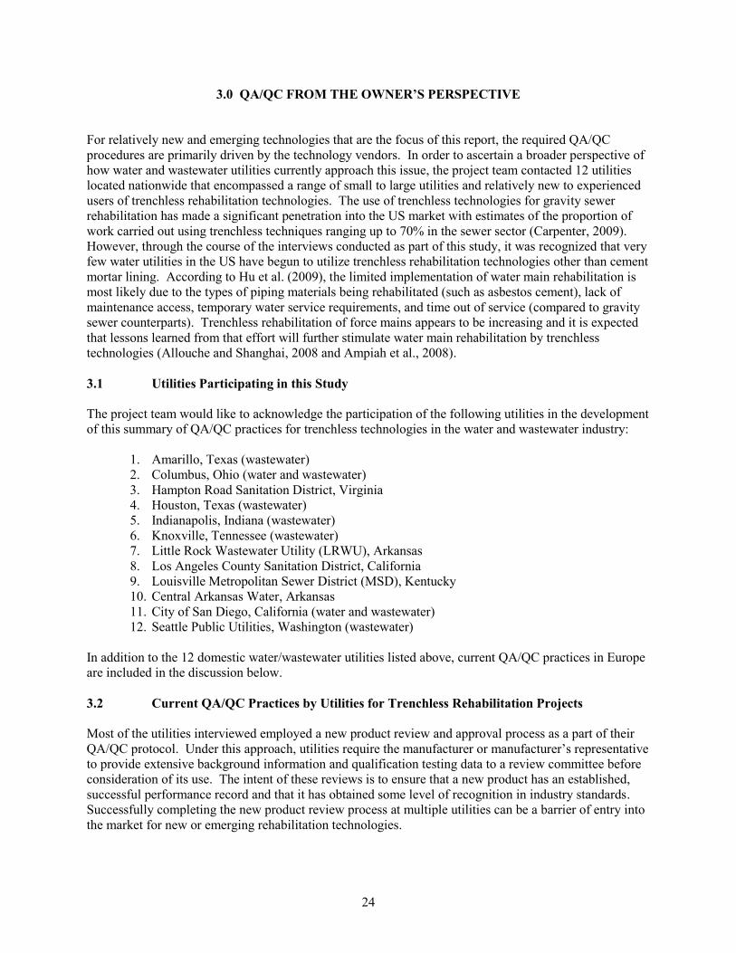
3.0 QA/QC FROM THE OWNER’S PERSPECTIVE
For relatively new and emerging technologies that are the focus of this report, the required QA/QC
procedures are primarily driven by the technology vendors. In order to ascertain a broader perspective of
how water and wastewater utilities currently approach this issue, the project team contacted 12 utilities
located nationwide that encompassed a range of small to large utilities and relatively new to experienced
users of trenchless rehabilitation technologies. The use of trenchless technologies for gravity sewer
rehabilitation has made a significant penetration into the US market with estimates of the proportion of
work carried out using trenchless techniques ranging up to 70% in the sewer sector (Carpenter, 2009).
However, through the course of the interviews conducted as part of this study, it was recognized that very
few water utilities in the US have begun to utilize trenchless rehabilitation technologies other than cement
mortar lining. According to Hu et al. (2009), the limited implementation of water main rehabilitation is
most likely due to the types of piping materials being rehabilitated (such as asbestos cement), lack of
maintenance access, temporary water service requirements, and time out of service (compared to gravity
sewer counterparts). Trenchless rehabilitation of force mains appears to be increasing and it is expected
that lessons learned from that effort will further stimulate water main rehabilitation by trenchless
technologies (Allouche and Shanghai, 2008 and Ampiah et al., 2008).
3.1 Utilities Participating in this Study
The project team would like to acknowledge the participation of the following utilities in the development
of this summary of QA/QC practices for trenchless technologies in the water and wastewater industry:
1. Amarillo, Texas (wastewater)
2. Columbus, Ohio (water and wastewater)
3. Hampton Road Sanitation District, Virginia
4. Houston, Texas (wastewater)
5. Indianapolis, Indiana (wastewater)
6. Knoxville, Tennessee (wastewater)
7. Little Rock Wastewater Utility (LRWU), Arkansas
8. Los Angeles County Sanitation District, California
9. Louisville Metropolitan Sewer District (MSD), Kentucky
10. Central Arkansas Water, Arkansas
11. City of San Diego, California (water and wastewater)
12. Seattle Public Utilities, Washington (wastewater)
In addition to the 12 domestic water/wastewater utilities listed above, current QA/QC practices in Europe
are included in the discussion below.
3.2 Current QA/QC Practices by Utilities for Trenchless Rehabilitation Projects
Most of the utilities interviewed employed a new product review and approval process as a part of their
QA/QC protocol. Under this approach, utilities require the manufacturer or manufacturer‟s representative
to provide extensive background information and qualification testing data to a review committee before
consideration of its use. The intent of these reviews is to ensure that a new product has an established,
successful performance record and that it has obtained some level of recognition in industry standards.
Successfully completing the new product review process at multiple utilities can be a barrier of entry into
the market for new or emerging rehabilitation technologies.
24
Utility Case Study
City of Columbus Evaluation and Approval of New Sewer Collection System Products
The City of Columbus Division of Sewerage and Drainage (DOSD) has established a DOSD New Products Committee to
review and approve products to be used for the construction, maintenance, and rehabilitation of the City‟s sanitary,
combined, and storm sewers (City of Columbus DOSD, 2007). The review process is conducted in four phases
including: 1) a written request from the manufacturer to DOSD for review; 2) a preliminary review of key product
criteria; 3) a certificate of preliminary approval; and 4) then full approval status or rejection of the product based on the
final product evaluation.
In the first phase, the manufacturer requests consideration of their product through a written request to the DOSD
Administrator. The information in the request includes the following: 1) the name of the product and how it is used; 2)
potential cost savings from its use over the project life-cycle; 3) approvals received from other municipalities or agencies;
and 4) the time period on the market.
If the DOSD Administrator decides that the product warrants further consideration, then the manufacturer can request a
preliminary evaluation by submitting a set of eighteen criteria for new sewer collection system products. The key criteria
to be considered include: 1) applicable ASTM, American Association of State Highway and Transportation Officials
(AASHTO), or NASSCO specifications and vendor-recommended construction specifications; 2) recent material testing
data completed within the past 3 years and performed by an independent laboratory; 3) a list of environmental benefits of
the product; 4) three references for municipal users of the technology in the past 3 years; 5) a list of current regional
projects for potential site visits; 6) production facility information for potential plant visit; 7) manufacturer expected
service life of product and supporting data; 8) shop and working drawings; 9) detailed installation, maintenance, and
repair instructions and manuals; 10) storage and handling instructions; 11) list of spare parts and lead time; 12)
instructions on how to make future connections to product; 13) list of suppliers; 14) list of possible installation problems
and defects; 15) available training; 16) points of contact for technical support; 17) notification of any changes to product;
and 18) additional documentation as requested.
If it is determined that the new product meets or exceeds all of the preliminary evaluation criteria based on the
information submittal above, then the DOSD and manufacturer execute a “Certificate of Preliminary Approval of New
Sewer Collection Products.” This certificate is good for a period of three years during which time the manufacturer is
asked to demonstrate their product within a section of the collection system designated by the City and to provide video
or photographic documentation of the installed product. Testing data from this installation is also requested. A warranty
period of three years is requested for all permanent installations. After this time period, the product will be evaluated for
full approval status if appropriate.
Owing to the proprietary nature of the trenchless rehabilitation technologies in this study, it was
determined that the specifications prepared by the utilities for their construction contracts typically follow
the technology vendors‟ recommendations. This practice has led to the use of prescriptive style
specifications for contract documents (see text box). This may lead to less focus from the owner and/or
the owner‟s engineering representative on the needed qualities of the installed improvements over a long-
term operational perspective. Using the short-term testing supplied by the technology vendor as evidence
of suitability for the proposed application, the project specifications are generated for achieving those
finished qualities. It is then the passing or failing of these parameters that determine whether or not a
successful installation has occurred.
During the interview process with the utilities, it was determined that several of the QA steps
recommended by the technology vendors, and incorporated into the contract documents, were being
treated as optional. As such, these QA steps were typically not executed by the owner or the owner‟s
engineering representative during the installation phase of the project. This was especially true in the
case of a contractor or installer who had already completed several projects for a particular owner.
Consequently, many times, the acceptance process for these improvements evolved into a discussion
25
Prescriptive Style Specifications
Prescriptive Style Specifications
Clauses are used that define the means and methods of constructing the improvements
Intended end performance requirements of the improvements are not stated
o Structural end performance
o Water-tightness end performance
Design of improvements
o Design procedure is mandated
o Design parameters are mandated
Acceptance protocol
o Visual documentation of improvements for fit and finish
o Physical properties testing of materials installed
around the submitted final CCTV inspection of the work. This often resulted in any visual imperfections
being noted in the review of the videos and typically defaulting to a discussion seeking a compromise
from the owner to accept the installed improvements “as-is” without testing any physical properties.
The owners are, in essence, banking on the technology vendors to ensure or warranty that the quality
demonstrated in their respective qualification testing was achieved by the installers in the field. In
addition, the utilities are relying on the product‟s life cycle performance claims to be guaranteed by their
agreements with their respective installers and the vendor‟s desire to grow the use of their technology in
the future.
Further hampering the QA process is the fact that construction observation is generally done on an
intermittent basis (if at all) for rehabilitation projects. Without someone representing the owner onsite
during construction, there is no chain-of-custody for physical samples if they are taken to ensure that they
are representative of the actual installation. Further, there is no way for the owner to know if the
contractor is following the specifications and/or the installation procedures that were submitted at the pre-
construction meeting. Of the utilities interviewed, only 2 out of the 12 utilities had full-time construction
observation of their trenchless technology projects. The lack of well trained construction observers
and/or their associated costs were the most cited reasons for not providing rehabilitation projects with
full-time construction observation.
Performance specifications are being used with a greater frequency to overcome the perceived short
comings of the prescriptive style of specification documents and the proprietary nature of the
improvements being implemented (see text box). If the contract documents can be written to properly
convey the project‟s end performance goals, the contractors and technology vendors will be required to
deliver technically appropriate and properly installed solutions to meet the given application needs.
While this trend can overcome issues with the identification of QA needs for the installation, it still does
not address the need for the owner‟s engineer to become technically competent in the suite of available
trenchless technologies. This understanding is essential to making the required analysis during the design
phase of the project in order to select the most cost-effective solution(s) for the owner‟s rehabilitation
needs.
NASSCO realized the need for improved selection of the applicable trenchless technologies during the
design phase and properly crafted performance-based specifications for implementing these choices into
the project specifications. NASSCO worked with the Louisiana Tech University Trenchless Technology
Center (TTC) to develop the Trenchless Assessment Guide – Rehabilitation (TAG-R) to assist the design
26
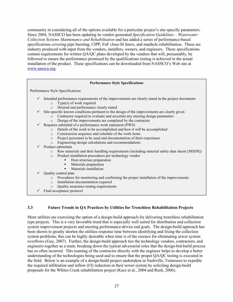
3.3
community in considering all of the options available for a particular project‟s site-specific parameters.
Since 2004, NASSCO has been updating its vendor-generated Specification Guidelines – Wastewater
Collection Systems Maintenance and Rehabilitation and has added a series of performance-based
specifications covering pipe bursting, CIPP, FnF close-fit liners, and manhole rehabilitation. These are
industry produced with input from the vendors, installers, owners, and engineers. These specifications
contain requirements for written QA/QC plans developed by the vendors that will, presumably, be
followed to ensure the performance promised by the qualifications testing is achieved in the actual
installation of the product. These specifications can be downloaded from NASSCO‟s Web site at
www.nassco.org.
Performance Style Specifications
Performance Style Specifications
Intended performance requirements of the improvements are clearly stated in the project documents
o Type(s) of work required
o Desired end performance clearly stated
Site-specific known conditions pertinent to the design of the improvements are clearly given
o Contractor required to evaluate and ascertain any missing design parameters
o Design of the improvements are completed by the contractor
Requires submittal of a performance work statement (PWS)
o Details of the work to be accomplished and how it will be accomplished
o Construction sequence and schedule of the work items
o Project personnel to be used and documentation of their experience
o Engineering design calculations and recommendations
Product submittals
o Raw materials and their handling requirements (including material safety data sheets [MSDS])
o Product installation procedures per technology vendor
Host structure preparation
Materials preparation
Materials installation
Quality control plan
o Procedures for monitoring and confirming the proper installation of the improvements
o Installation documentation required
o Quality assurance testing requirements
Final acceptance protocol
Future Trends in QA Practices by Utilities for Trenchless Rehabilitation Projects
More utilities are exercising the option of a design-build approach for delivering trenchless rehabilitation
type projects. This is a very favorable trend that is especially well suited for distribution and collection
system improvement projects and meeting performance-driven end goals. The design-build approach has
been shown to greatly shorten the utilities response time between identifying and fixing the collection
system problems; this can be highly desirable when time is of the essence for eliminating sewer system
overflows (Guy, 2007). Further, the design-build approach ties the technology vendors, contractors, and
engineers together as a team, breaking down the typical adversarial roles that the design-bid-build process
has so often incurred. This teaming of the contractor directly with the engineer helps to develop a better
understanding of the technologies being used and to ensure that the proper QA/QC testing is executed in
the field. Below is an example of a design-build project undertaken in Nashville, Tennessee to expedite
the required infiltration and inflow (I/I) reduction in their sewer system by soliciting design-build
proposals for the Whites Creek rehabilitation project (Kurz et al., 2004 and Rush, 2006).
27
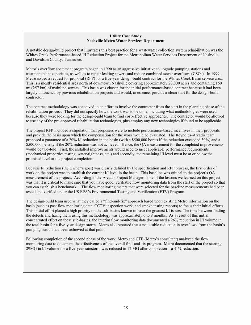
Utility Case Study
Nashville Metro Water Services Department
A notable design-build project that illustrates this best practice for a wastewater collection system rehabilitation was the
Whites Creek Performance-based I/I Reduction Project for the Metropolitan Water Services Department of Nashville
and Davidson County, Tennessee.
Metro‟s overflow abatement program began in 1990 as an aggressive initiative to upgrade pumping stations and
treatment plant capacities, as well as to repair leaking sewers and reduce combined sewer overflows (CSOs). In 1999,
Metro issued a request for proposal (RFP) for a five-year design-build contract for the Whites Creek Basin service area.
This is a mostly residential area north of downtown Nashville covering approximately 20,000 acres and containing 160
mi (257 km) of mainline sewers. This basin was chosen for the initial performance-based contract because it had been
largely untouched by previous rehabilitation projects and would, in essence, provide a clean start for the design-build
contractor.
The contract methodology was conceived in an effort to involve the contractor from the start in the planning phase of the
rehabilitation process. They did not specify how the work was to be done, including what methodologies were used,
because they were looking for the design-build team to find cost-effective approaches. The contractor would be allowed
to use any of the pre-approved rehabilitation technologies, plus employ any new technologies if found to be applicable.
The project RFP included a stipulation that proposers were to include performance-based incentives in their proposals
and provide the basis upon which the compensation for the work would be evaluated. The Reynolds-Arcadis team
proposed a guarantee of a 20% I/I reduction in the basin (with a $500,000 bonus if the reduction exceeded 30%) and a
$500,000 penalty if the 20% reduction was not achieved. Hence, the QA measurement for the completed improvements
would be two-fold. First, the installed improvements would need to meet applicable performance requirements
(mechanical properties testing, water-tightness, etc.) and secondly, the remaining I/I level must be at or below the
promised level at the project completion.
Because I/I reduction (the Owner‟s goal) was clearly defined by the specification and RFP process, the first order of
work on the project was to establish the current I/I level in the basin. This baseline was critical to the project‟s QA
measurement of the project. According to the Arcadis Project Manager, “one of the lessons we learned on this project
was that it is critical to make sure that you have good, verifiable flow monitoring data from the start of the project so that
you can establish a benchmark.“ The flow monitoring meters that were selected for the baseline measurements had been
tested and verified under the US EPA‟s Environmental Testing and Verification (ETV) Program.
The design-build team used what they called a “find-and-fix” approach based upon existing Metro information on the
basin (such as past flow monitoring data, CCTV inspection work, and smoke testing reports) to focus their initial efforts.
This initial effort placed a high priority on the sub-basins known to have the greatest I/I issues. The time between finding
the defects and fixing them using this methodology was approximately 6 to 8 months. As a result of this initial
concentrated effort on these sub-basins, the interim flow monitoring data documented a 26% reduction in I/I volume in
the total basin for a five-year design storm. Metro also reported that a noticeable reduction in overflows from the basin‟s
pumping station had been achieved at that point.
Following completion of the second phase of the work, Metro and CTE (Metro‟s consultant) analyzed the flow
monitoring data to document the effectiveness of the overall find-and-fix program. Metro documented that the starting
29MG in I/I volume for a five-year rainstorm was reduced to 17 MG after completion – a 41% reduction.
28
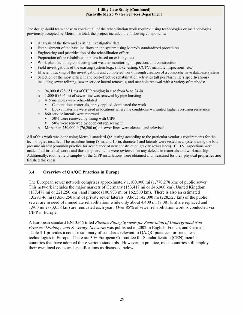
Utility Case Study (Continued)
Nashville Metro Water Services Department
The design-build team chose to conduct all of the rehabilitation work required using technologies or methodologies
previously accepted by Metro. In total, the project included the following components:
Analysis of the flow and existing investigative data
Establishment of the baseline flows in the system using Metro‟s standardized procedures
Engineering and prioritization of the rehabilitation efforts
Preparation of the rehabilitation plans based on existing data
Work plan, including conducting wet weather monitoring, inspection, and construction
Field investigations of the existing system (e.g., smoke testing, CCTV, manhole inspections, etc.)
Efficient tracking of the investigations and completed work through creation of a comprehensive database system
Selection of the most efficient and cost-effective rehabilitation activities (all per Nashville‟s specifications)
including sewer relining, sewer service lateral renewals, and manhole renewal with a variety of methods:
o 94,000 ft (28,651 m) of CIPP r anging in size from 8- to 24-in.
o 1,000 ft (305 m) of sewer line was renewed by pipe bursting
o 415 manholes were rehabilitated
Cementitious materials, spray applied, dominated the work
Epoxy materials were used in locations where the conditions warranted higher corrosion resistance
o 860 service laterals were renewed
50% were renewed by lining with CIPP
50% were renewed by open cut replacement
o More than 250,000 ft (76,200 m) of sewer lines were cleaned and televised
All of this work was done using Metro‟s standard QA testing according to the particular vendor‟s requirements for the
technologies installed. The mainline lining (8-in. and 10-in. diameter) and laterals were tested as a system using the low
pressure air test (common practice for acceptance of new construction gravity sewer lines). CCTV inspections were
made of all installed works and those improvements were reviewed for any defects in materials and workmanship.
Additionally, routine field samples of the CIPP installations were obtained and measured for their physical properties and finished thickness.
3.4 Overview of QA/QC Practices in Europe
The European sewer network comprises approximately 1,100,000 mi (1,770,278 km) of public sewer.
This network includes the major markets of Germany (153,417 mi or 246,900 km), United Kingdom
(137,478 mi or 221,250 km), and France (100,973 mi or 162,500 km). There is also an estimated
1,029,146 mi (1,656,250 km) of private sewer laterals. About 142,000 mi (228,527 km) of the public
sewer are in need of immediate rehabilitation, while only about 4,400 mi (7,081 km) are replaced and
1,900 miles (3,058 km) are renovated each year. Over 85% of sewer rehabilitation work is conducted via
CIPP in Europe.
A European standard EN13566 titled Plastics Piping Systems for Renovation of Underground Non-
Pressure Drainage and Sewerage Networks was published in 2002 in English, French, and German.
Table 3-1 provides a concise summary of standards relevant to QA/QC practices for trenchless
technologies in Europe. There are 30+ European Committee for Standardization (CEN) member
countries that have adopted these various standards. However, in practice, most countries still employ
their own local codes and specifications as discussed below.
29
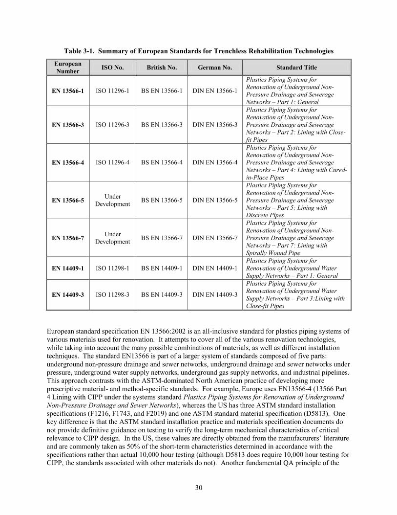
Table 3-1. Summary of European Standards for Trenchless Rehabilitation Technologies
European
Number ISO No. British No. German No. Standard Title
EN 13566-1 ISO 11296-1 BS EN 13566-1 DIN EN 13566-1
Plastics Piping Systems for
Renovation of Underground Non-
Pressure Drainage and Sewerage
Networks – Part 1: General
EN 13566-3 ISO 11296-3 BS EN 13566-3 DIN EN 13566-3
Plastics Piping Systems for
Renovation of Underground Non-
Pressure Drainage and Sewerage
Networks – Part 2: Lining with Close-
fit Pipes
EN 13566-4 ISO 11296-4 BS EN 13566-4 DIN EN 13566-4
Plastics Piping Systems for
Renovation of Underground Non-
Pressure Drainage and Sewerage
Networks – Part 4: Lining with Cured-
in-Place Pipes
EN 13566-5 Under
Development BS EN 13566-5 DIN EN 13566-5
Plastics Piping Systems for
Renovation of Underground Non-
Pressure Drainage and Sewerage
Networks – Part 5: Lining with
Discrete Pipes
EN 13566-7 Under
Development BS EN 13566-7 DIN EN 13566-7
Plastics Piping Systems for
Renovation of Underground Non-
Pressure Drainage and Sewerage
Networks – Part 7: Lining with
Spirally Wound Pipe
EN 14409-1 ISO 11298-1 BS EN 14409-1 DIN EN 14409-1
Plastics Piping Systems for
Renovation of Underground Water
Supply Networks – Part 1: General
EN 14409-3 ISO 11298-3 BS EN 14409-3 DIN EN 14409-3
Plastics Piping Systems for
Renovation of Underground Water
Supply Networks – Part 3:Lining with
Close-fit Pipes
European standard specification EN 13566:2002 is an all-inclusive standard for plastics piping systems of
various materials used for renovation. It attempts to cover all of the various renovation technologies,
while taking into account the many possible combinations of materials, as well as different installation
techniques. The standard EN13566 is part of a larger system of standards composed of five parts:
underground non-pressure drainage and sewer networks, underground drainage and sewer networks under
pressure, underground water supply networks, underground gas supply networks, and industrial pipelines.
This approach contrasts with the ASTM-dominated North American practice of developing more
prescriptive material- and method-specific standards. For example, Europe uses EN13566-4 (13566 Part
4 Lining with CIPP under the systems standard Plastics Piping Systems for Renovation of Underground
Non-Pressure Drainage and Sewer Networks), whereas the US has three ASTM standard installation
specifications (F1216, F1743, and F2019) and one ASTM standard material specification (D5813). One
key difference is that the ASTM standard installation practice and materials specification documents do
not provide definitive guidance on testing to verify the long-term mechanical characteristics of critical
relevance to CIPP design. In the US, these values are directly obtained from the manufacturers‟ literature
and are commonly taken as 50% of the short-term characteristics determined in accordance with the
specifications rather than actual 10,000 hour testing (although D5813 does require 10,000 hour testing for
CIPP, the standards associated with other materials do not). Another fundamental QA principle of the
30
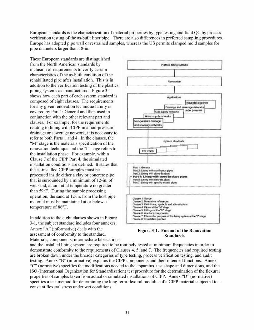
European standards is the characterization of material properties by type testing and field QC by process
verification testing of the as-built liner pipe. There are also differences in preferred sampling procedures.
Europe has adopted pipe wall or restrained samples, whereas the US permits clamped mold samples for
pipe diameters larger than 18-in.
These European standards are distinguished
from the North American standards by
inclusion of requirements to verify certain
characteristics of the as-built condition of the
rehabilitated pipe after installation. This is in
addition to the verification testing of the plastics
piping systems as manufactured. Figure 3-1
shows how each part of each system standard is
composed of eight clauses. The requirements
for any given renovation technique family is
covered by Part 1: General and then used in
conjunction with the other relevant part and
clauses. For example, for the requirements
relating to lining with CIPP in a non-pressure
drainage or sewerage network, it is necessary to
refer to both Parts 1 and 4. In the clauses, the
“M” stage is the materials specification of the
renovation technique and the “I” stage refers to
the installation phase. For example, within
Clause 7 of the CIPP Part 4, the simulated
installation conditions are defined. It states that
the as-installed CIPP samples must be
processed inside either a clay or concrete pipe
that is surrounded by a minimum of 12-in. of
wet sand, at an initial temperature no greater
than 59⁰F. During the sample processing
operation, the sand at 12-in. from the host pipe
material must be maintained at or below a
temperature of 86⁰F.
In addition to the eight clauses shown in Figure
3-1, the subject standard includes four annexes.
Annex “A” (informative) deals with the
assessment of conformity to the standard.
Materials, components, intermediate fabrications,
and the installed lining system are required to be routinely tested at minimum frequencies in order to
demonstrate conformity to the requirements of Clauses 4, 5, and 7. The frequencies and required testing
are broken down under the broader categories of type testing, process verification testing, and audit
testing. Annex “B” (informative) explains the CIPP components and their intended functions. Annex
“C” (normative) specifies the modifications needed to the apparatus, test shape and dimensions, and the
ISO (International Organization for Standardization) test procedure for the determination of the flexural
properties of samples taken from actual or simulated installations of CIPP. Annex “D” (normative)
specifies a test method for determining the long-term flexural modulus of a CIPP material subjected to a
constant flexural stress under wet conditions.
Figure 3-1. Format of the Renovation
Standards
31
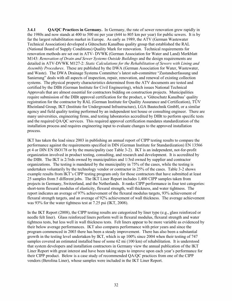
3.4.1 QA/QC Practices in Germany. In Germany, the rate of sewer renovation grew rapidly in
the 1980s and now stands at 400 to 500 mi per year (644 to 805 km per year) for public sewers. It is by
far the largest rehabilitation market in Europe. As early as 1989, the ATV (German Wastewater
Technical Association) developed a Güteschutz Kanalbau quality group that established the RAL
(National Board of Supply Conditions) Quality Mark for renovation. Technical requirements for
renovation methods are set out in ATV- DVWK (German Association for Water and Land) Merkblatt
M143: Renovation of Drain and Sewer Systems Outside Buildings and the design requirements are
detailed in ATV-DVWK M127-2: Static Calculations for the Rehabilitation of Sewers with Lining and
Assembly Procedures. These are published by the DWA (German Association for Water, Wastewater,
and Waste). The DWA Drainage Systems Committee‟s latest sub-committee “Zustandserfassung und
Sanierung” deals with all aspects of inspection, repair, renovation, and renewal of existing collection
systems. The physical property characteristics determined from the ATV documents are tested and
certified by the DIBt (German Institute for Civil Engineering), which issues National Technical
Approvals that are almost essential for contractors bidding on construction projects. Municipalities
require submission of the DIBt approval certification for the product, a „Güteschutz Kanalbau‟ quality
registration for the contractor by RAL (German Institute for Quality Assurance and Certification), TÜV
Rheinland Group, IKT (Institute for Underground Infrastructure), LGA Bautechnik GmbH, or a similar
agency and field quality testing performed by an independent test house or consulting engineer. There are
many universities, engineering firms, and testing laboratories accredited by DIBt to perform specific tests
and the required QA/QC services. This required approval certification mandates standardization of the
installation process and requires engineering input to evaluate changes to the approved installation
process.
IKT has taken the lead since 2003 in publishing an annual report of CIPP testing results to compare the
performance against the requirements specified in DIN (German Institute for Standardization) EN 13566
pt 4 or DIN EN ISO178 or by the municipality (see Table 3-2). IKT is an independent, not-for-profit
organization involved in product testing, consulting, and research and development. It is accredited by
the DIBt. The IKT is 2/3rds owned by municipalities and 1/3rd owned by supplier and contractor
organizations. The testing is mandated by the municipality in 75% of the cases, while the testing is
undertaken voluntarily by the technology vendor or contractor in 25% of the cases. Table 3-2 shows
example results from IKT‟s CIPP testing program only for those contractors that have submitted at least
25 samples from 5 different jobs. The IKT Liner Report includes 1,400 CIPP samples taken from
projects in Germany, Switzerland, and the Netherlands. It ranks CIPP performance in four test categories:
short-term flexural modulus of elasticity, flexural strength, wall thickness, and water tightness. The
report indicates an average of 97% achievement of the flexural modulus targets, 93% achievement of
flexural strength targets, and an average of 92% achievement of wall thickness. The average achievement
was 93% for the water tightness test at 7.25 psi (IKT, 2008).
In the IKT Report (2008), the CIPP testing results are categorized by liner type (e.g., glass reinforced or
needle felt liner). Glass reinforced liners perform well in flexural modulus, flexural strength and water
tightness tests, but less well in wall thickness tests. Felt liners appear to be more variable as evidenced by
their below average performances. IKT also compares performance with prior years and since the
program commenced in 2003 there has been a steady improvement. There has also been a substantial
growth in the testing level undertaken by IKT, which is up 100% since 2004 when their testing of 747
samples covered an estimated installed base of some 62 mi (100 km) of rehabilitation. It is understood
that system developers and installation contractors in Germany view the annual publication of the IKT
Liner Report with great interest and have been taking steps to improve upon each year‟s performance for
their CIPP product. Below is a case study of recommended QA/QC practices from one of the CIPP
vendors (Berolina Liner), whose samples were included in the IKT Liner Report.
32
Table 3-2. Example of QA/QC Tests Performed by IKT on CIPP Liners (IKT, 2008)
33
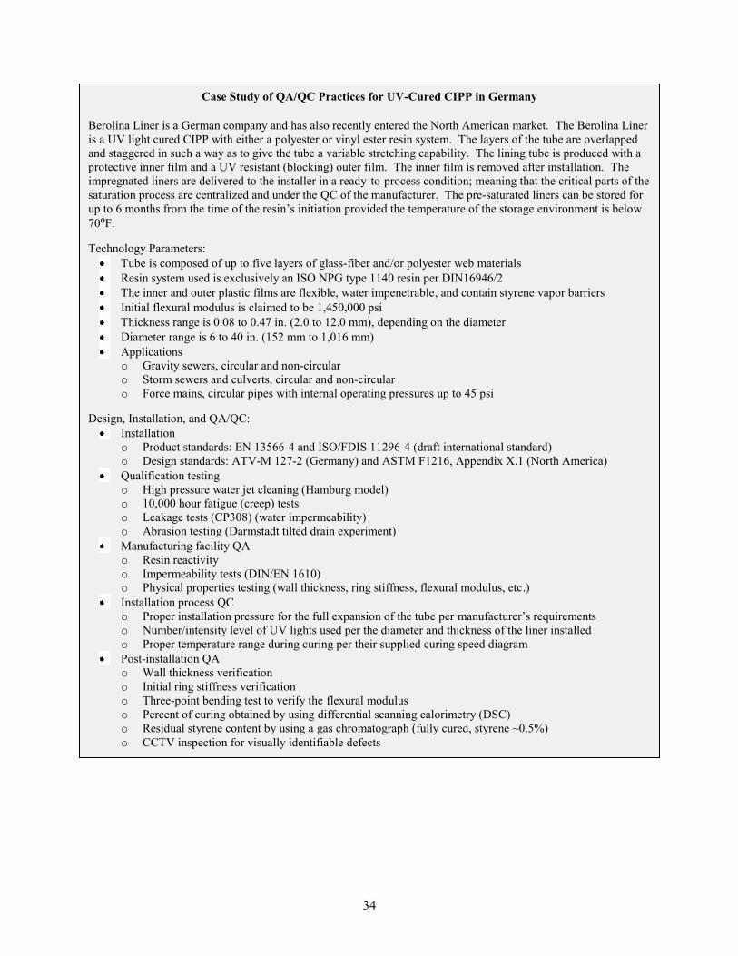
Case Study of QA/QC Practices for UV-Cured CIPP in Germany
Berolina Liner is a German company and has also recently entered the North American market. The Berolina Liner
is a UV light cured CIPP with either a polyester or vinyl ester resin system. The layers of the tube are overlapped
and staggered in such a way as to give the tube a variable stretching capability. The lining tube is produced with a
protective inner film and a UV resistant (blocking) outer film. The inner film is removed after installation. The
impregnated liners are delivered to the installer in a ready-to-process condition; meaning that the critical parts of the
saturation process are centralized and under the QC of the manufacturer. The pre-saturated liners can be stored for
up to 6 months from the time of the resin‟s initiation provided the temperature of the storage environment is below
70⁰F.
Technology Parameters:
Tube is composed of up to five layers of glass-fiber and/or polyester web materials
Resin system used is exclusively an ISO NPG type 1140 resin per DIN16946/2
The inner and outer plastic films are flexible, water impenetrable, and contain styrene vapor barriers
Initial flexural modulus is claimed to be 1,450,000 psi
Thickness range is 0.08 to 0.47 in. (2.0 to 12.0 mm), depending on the diameter
Diameter range is 6 to 40 in. (152 mm to 1,016 mm)
Applications
o Gravity sewers, circular and non-circular
o Storm sewers and culverts, circular and non-circular
o Force mains, circular pipes with internal operating pressures up to 45 psi
Design, Installation, and QA/QC:
Installation
o Product standards: EN 13566-4 and ISO/FDIS 11296-4 (draft international standard)
o Design standards: ATV-M 127-2 (Germany) and ASTM F1216, Appendix X.1 (North America)
Qualification testing
o High pressure water jet cleaning (Hamburg model)
o 10,000 hour fatigue (creep) tests
o Leakage tests (CP308) (water impermeability)
o Abrasion testing (Darmstadt tilted drain experiment)
Manufacturing facility QA
o Resin reactivity
o Impermeability tests (DIN/EN 1610)
o Physical properties testing (wall thickness, ring stiffness, flexural modulus, etc.)
Installation process QC
o Proper installation pressure for the full expansion of the tube per manufacturer‟s requirements
o Number/intensity level of UV lights used per the diameter and thickness of the liner installed
o Proper temperature range during curing per their supplied curing speed diagram
Post-installation QA
o Wall thickness verification
o Initial ring stiffness verification
o Three-point bending test to verify the flexural modulus
o Percent of curing obtained by using differential scanning calorimetry (DSC)
o Residual styrene content by using a gas chromatograph (fully cured, styrene ~0.5%)
o CCTV inspection for visually identifiable defects
34
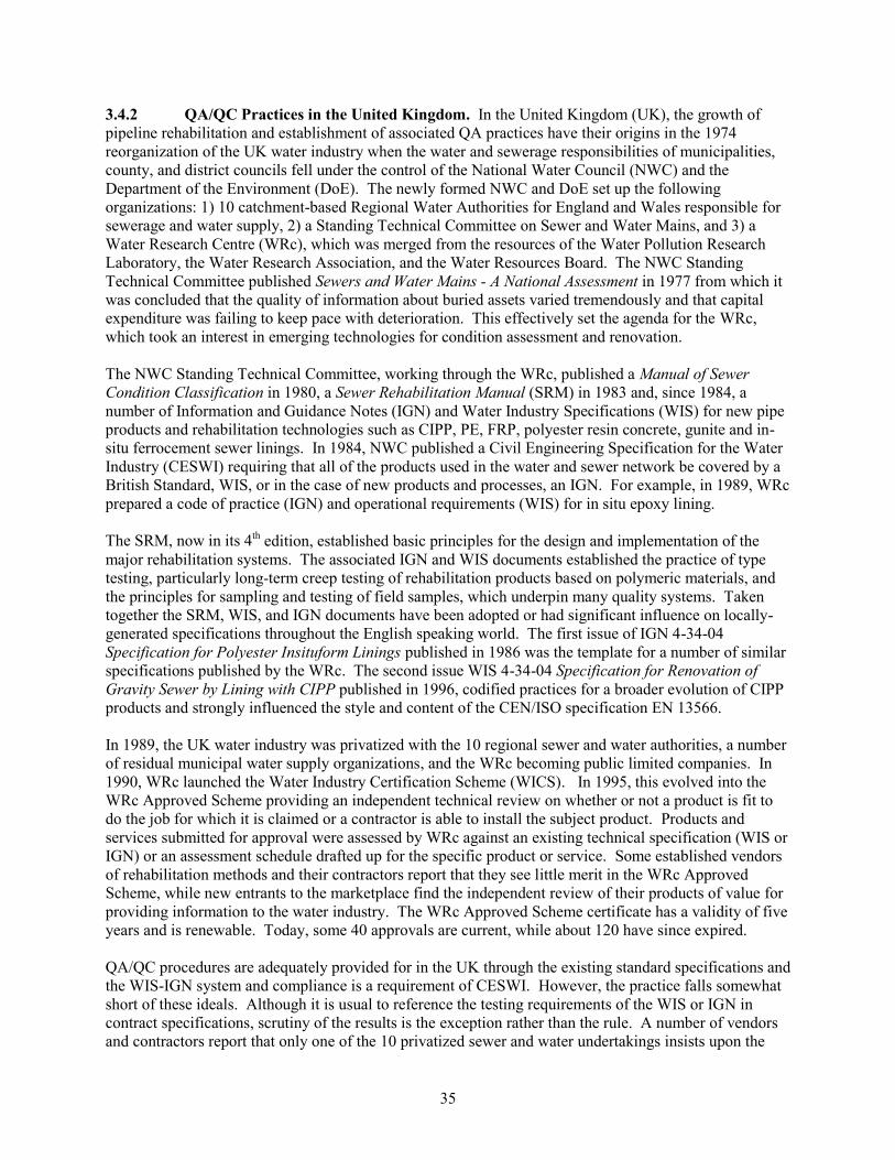
3.4.2 QA/QC Practices in the United Kingdom. In the United Kingdom (UK), the growth of
pipeline rehabilitation and establishment of associated QA practices have their origins in the 1974
reorganization of the UK water industry when the water and sewerage responsibilities of municipalities,
county, and district councils fell under the control of the National Water Council (NWC) and the
Department of the Environment (DoE). The newly formed NWC and DoE set up the following
organizations: 1) 10 catchment-based Regional Water Authorities for England and Wales responsible for
sewerage and water supply, 2) a Standing Technical Committee on Sewer and Water Mains, and 3) a
Water Research Centre (WRc), which was merged from the resources of the Water Pollution Research
Laboratory, the Water Research Association, and the Water Resources Board. The NWC Standing
Technical Committee published Sewers and Water Mains - A National Assessment in 1977 from which it
was concluded that the quality of information about buried assets varied tremendously and that capital
expenditure was failing to keep pace with deterioration. This effectively set the agenda for the WRc,
which took an interest in emerging technologies for condition assessment and renovation.
The NWC Standing Technical Committee, working through the WRc, published a Manual of Sewer
Condition Classification in 1980, a Sewer Rehabilitation Manual (SRM) in 1983 and, since 1984, a
number of Information and Guidance Notes (IGN) and Water Industry Specifications (WIS) for new pipe
products and rehabilitation technologies such as CIPP, PE, FRP, polyester resin concrete, gunite and in-
situ ferrocement sewer linings. In 1984, NWC published a Civil Engineering Specification for the Water
Industry (CESWI) requiring that all of the products used in the water and sewer network be covered by a
British Standard, WIS, or in the case of new products and processes, an IGN. For example, in 1989, WRc
prepared a code of practice (IGN) and operational requirements (WIS) for in situ epoxy lining.
The SRM, now in its 4th edition, established basic principles for the design and implementation of the
major rehabilitation systems. The associated IGN and WIS documents established the practice of type
testing, particularly long-term creep testing of rehabilitation products based on polymeric materials, and
the principles for sampling and testing of field samples, which underpin many quality systems. Taken
together the SRM, WIS, and IGN documents have been adopted or had significant influence on locally-
generated specifications throughout the English speaking world. The first issue of IGN 4-34-04
Specification for Polyester Insituform Linings published in 1986 was the template for a number of similar
specifications published by the WRc. The second issue WIS 4-34-04 Specification for Renovation of
Gravity Sewer by Lining with CIPP published in 1996, codified practices for a broader evolution of CIPP
products and strongly influenced the style and content of the CEN/ISO specification EN 13566.
In 1989, the UK water industry was privatized with the 10 regional sewer and water authorities, a number
of residual municipal water supply organizations, and the WRc becoming public limited companies. In
1990, WRc launched the Water Industry Certification Scheme (WICS). In 1995, this evolved into the
WRc Approved Scheme providing an independent technical review on whether or not a product is fit to
do the job for which it is claimed or a contractor is able to install the subject product. Products and
services submitted for approval were assessed by WRc against an existing technical specification (WIS or
IGN) or an assessment schedule drafted up for the specific product or service. Some established vendors
of rehabilitation methods and their contractors report that they see little merit in the WRc Approved
Scheme, while new entrants to the marketplace find the independent review of their products of value for
providing information to the water industry. The WRc Approved Scheme certificate has a validity of five
years and is renewable. Today, some 40 approvals are current, while about 120 have since expired.
QA/QC procedures are adequately provided for in the UK through the existing standard specifications and
the WIS-IGN system and compliance is a requirement of CESWI. However, the practice falls somewhat
short of these ideals. Although it is usual to reference the testing requirements of the WIS or IGN in
contract specifications, scrutiny of the results is the exception rather than the rule. A number of vendors
and contractors report that only one of the 10 privatized sewer and water undertakings insists upon the
35
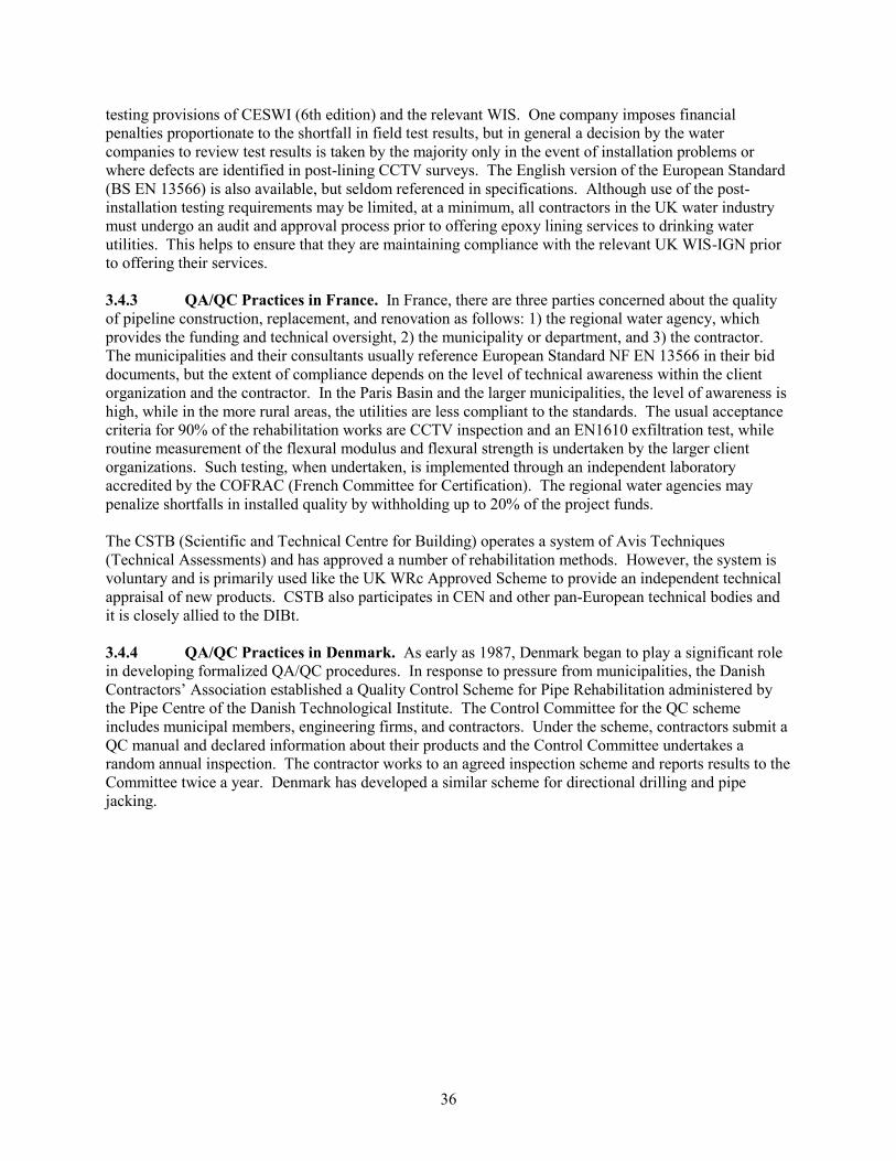
testing provisions of CESWI (6th edition) and the relevant WIS. One company imposes financial
penalties proportionate to the shortfall in field test results, but in general a decision by the water
companies to review test results is taken by the majority only in the event of installation problems or
where defects are identified in post-lining CCTV surveys. The English version of the European Standard
(BS EN 13566) is also available, but seldom referenced in specifications. Although use of the post-
installation testing requirements may be limited, at a minimum, all contractors in the UK water industry
must undergo an audit and approval process prior to offering epoxy lining services to drinking water
utilities. This helps to ensure that they are maintaining compliance with the relevant UK WIS-IGN prior
to offering their services.
3.4.3 QA/QC Practices in France. In France, there are three parties concerned about the quality
of pipeline construction, replacement, and renovation as follows: 1) the regional water agency, which
provides the funding and technical oversight, 2) the municipality or department, and 3) the contractor.
The municipalities and their consultants usually reference European Standard NF EN 13566 in their bid
documents, but the extent of compliance depends on the level of technical awareness within the client
organization and the contractor. In the Paris Basin and the larger municipalities, the level of awareness is
high, while in the more rural areas, the utilities are less compliant to the standards. The usual acceptance
criteria for 90% of the rehabilitation works are CCTV inspection and an EN1610 exfiltration test, while
routine measurement of the flexural modulus and flexural strength is undertaken by the larger client
organizations. Such testing, when undertaken, is implemented through an independent laboratory
accredited by the COFRAC (French Committee for Certification). The regional water agencies may
penalize shortfalls in installed quality by withholding up to 20% of the project funds.
The CSTB (Scientific and Technical Centre for Building) operates a system of Avis Techniques
(Technical Assessments) and has approved a number of rehabilitation methods. However, the system is
voluntary and is primarily used like the UK WRc Approved Scheme to provide an independent technical
appraisal of new products. CSTB also participates in CEN and other pan-European technical bodies and
it is closely allied to the DIBt.
3.4.4 QA/QC Practices in Denmark. As early as 1987, Denmark began to play a significant role
in developing formalized QA/QC procedures. In response to pressure from municipalities, the Danish
Contractors‟ Association established a Quality Control Scheme for Pipe Rehabilitation administered by
the Pipe Centre of the Danish Technological Institute. The Control Committee for the QC scheme
includes municipal members, engineering firms, and contractors. Under the scheme, contractors submit a
QC manual and declared information about their products and the Control Committee undertakes a
random annual inspection. The contractor works to an agreed inspection scheme and reports results to the
Committee twice a year. Denmark has developed a similar scheme for directional drilling and pipe
jacking.
36
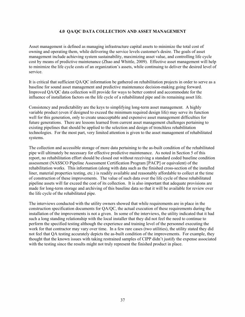
4.0 QA/QC DATA COLLECTION AND ASSET MANAGEMENT
Asset management is defined as managing infrastructure capital assets to minimize the total cost of
owning and operating them, while delivering the service levels customer's desire. The goals of asset
management include achieving system sustainability, maximizing asset value, and controlling life cycle
cost by means of predictive maintenance (Zhao and Whittle, 2009). Effective asset management will help
to minimize the life cycle costs of an organization‟s assets, while continuing to deliver the desired level of
service.
It is critical that sufficient QA/QC information be gathered on rehabilitation projects in order to serve as a
baseline for sound asset management and predictive maintenance decision-making going forward.
Improved QA/QC data collection will provide for ways to better control and accommodate for the
influence of installation factors on the life cycle of a rehabilitated pipe and its remaining asset life.
Consistency and predictability are the keys to simplifying long-term asset management. A highly
variable product (even if designed to exceed the minimum required design life) may serve its function
well for this generation, only to create unacceptable and expensive asset management difficulties for
future generations. There are lessons learned from current asset management challenges pertaining to
existing pipelines that should be applied to the selection and design of trenchless rehabilitation
technologies. For the most part, very limited attention is given to the asset management of rehabilitated
systems.
The collection and accessible storage of more data pertaining to the as-built condition of the rehabilitated
pipe will ultimately be necessary for effective predictive maintenance. As noted in Section 5 of this
report, no rehabilitation effort should be closed out without receiving a standard coded baseline condition
assessment (NASSCO Pipeline Assessment Certification Program [PACP] or equivalent) of the
rehabilitation works. This information (along with data such as the finished cross-section of the installed
liner, material properties testing, etc.) is readily available and reasonably affordable to collect at the time
of construction of these improvements. The value of such data over the life cycle of these rehabilitated
pipeline assets will far exceed the cost of its collection. It is also important that adequate provisions are
made for long-term storage and archiving of this baseline data so that it will be available for review over
the life cycle of the rehabilitated pipe.
The interviews conducted with the utility owners showed that while requirements are in place in the
construction specification documents for QA/QC, the actual execution of these requirements during the
installation of the improvements is not a given. In some of the interviews, the utility indicated that it had
such a long standing relationship with the local installer that they did not feel the need to continue to
perform the specified testing although the experience and training level of the personnel executing the
work for that contractor may vary over time. In a few rare cases (two utilities), the utility stated they did
not feel that QA testing accurately depicts the as-built condition of the improvements. For example, they
thought that the known issues with taking restrained samples of CIPP didn‟t justify the expense associated
with the testing since the results might not truly represent the finished product in place.
37
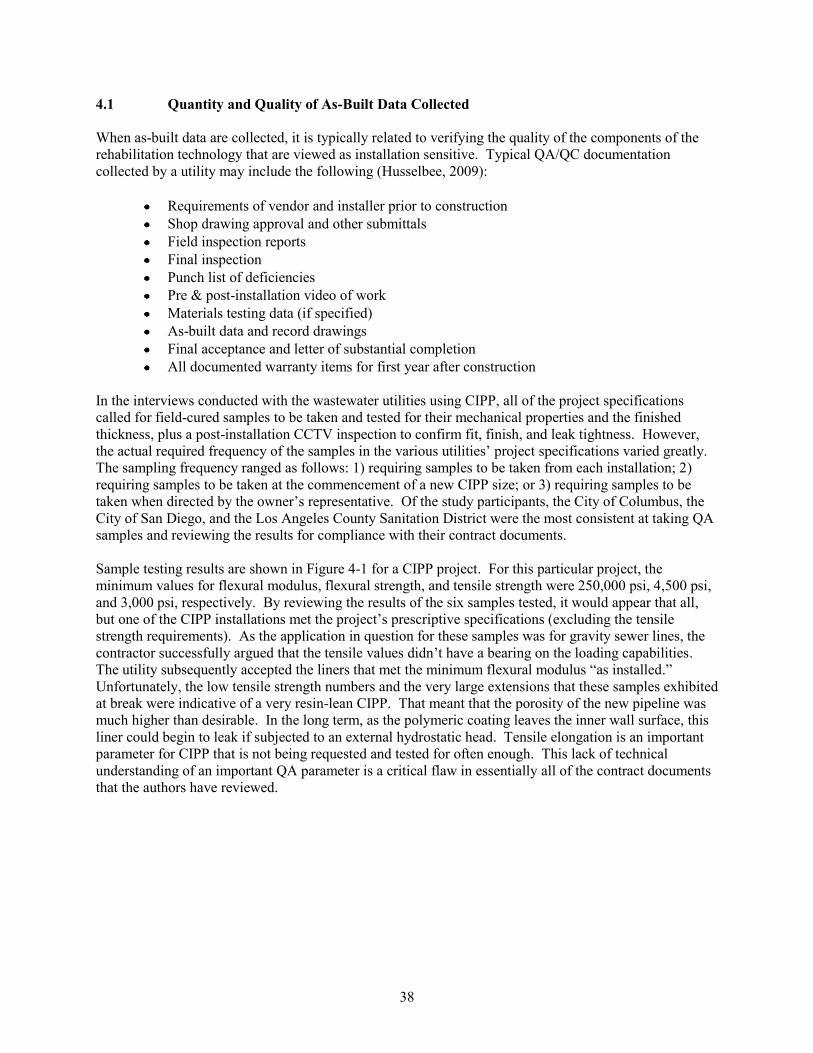
4.1 Quantity and Quality of As-Built Data Collected
When as-built data are collected, it is typically related to verifying the quality of the components of the
rehabilitation technology that are viewed as installation sensitive. Typical QA/QC documentation
collected by a utility may include the following (Husselbee, 2009):
Requirements of vendor and installer prior to construction
Shop drawing approval and other submittals
Field inspection reports
Final inspection
Punch list of deficiencies
Pre & post-installation video of work
Materials testing data (if specified)
As-built data and record drawings
Final acceptance and letter of substantial completion
All documented warranty items for first year after construction
In the interviews conducted with the wastewater utilities using CIPP, all of the project specifications
called for field-cured samples to be taken and tested for their mechanical properties and the finished
thickness, plus a post-installation CCTV inspection to confirm fit, finish, and leak tightness. However,
the actual required frequency of the samples in the various utilities‟ project specifications varied greatly.
The sampling frequency ranged as follows: 1) requiring samples to be taken from each installation; 2)
requiring samples to be taken at the commencement of a new CIPP size; or 3) requiring samples to be
taken when directed by the owner‟s representative. Of the study participants, the City of Columbus, the
City of San Diego, and the Los Angeles County Sanitation District were the most consistent at taking QA
samples and reviewing the results for compliance with their contract documents.
Sample testing results are shown in Figure 4-1 for a CIPP project. For this particular project, the
minimum values for flexural modulus, flexural strength, and tensile strength were 250,000 psi, 4,500 psi,
and 3,000 psi, respectively. By reviewing the results of the six samples tested, it would appear that all,
but one of the CIPP installations met the project‟s prescriptive specifications (excluding the tensile
strength requirements). As the application in question for these samples was for gravity sewer lines, the
contractor successfully argued that the tensile values didn‟t have a bearing on the loading capabilities.
The utility subsequently accepted the liners that met the minimum flexural modulus “as installed.”
Unfortunately, the low tensile strength numbers and the very large extensions that these samples exhibited
at break were indicative of a very resin-lean CIPP. That meant that the porosity of the new pipeline was
much higher than desirable. In the long term, as the polymeric coating leaves the inner wall surface, this
liner could begin to leak if subjected to an external hydrostatic head. Tensile elongation is an important
parameter for CIPP that is not being requested and tested for often enough. This lack of technical
understanding of an important QA parameter is a critical flaw in essentially all of the contract documents
that the authors have reviewed.
38
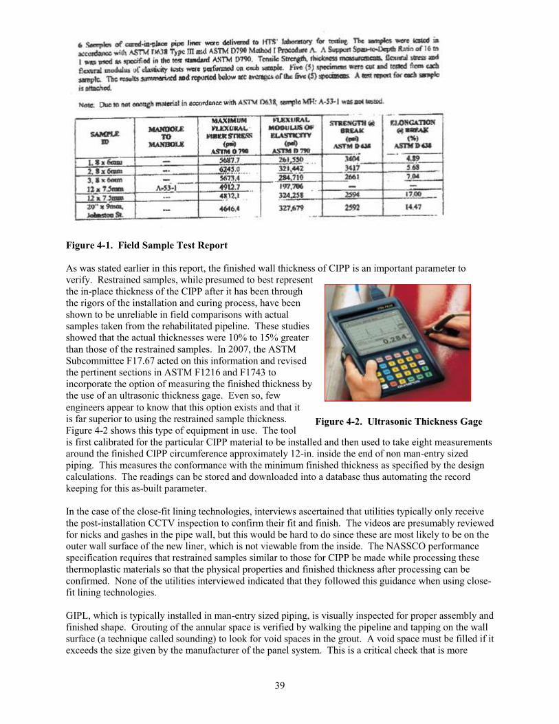
Figure 4-1. Field Sample Test Report
As was stated earlier in this report, the finished wall thickness of CIPP is an important parameter to
verify. Restrained samples, while presumed to best represent
the in-place thickness of the CIPP after it has been through
the rigors of the installation and curing process, have been
shown to be unreliable in field comparisons with actual
samples taken from the rehabilitated pipeline. These studies
showed that the actual thicknesses were 10% to 15% greater
than those of the restrained samples. In 2007, the ASTM
Subcommittee F17.67 acted on this information and revised
the pertinent sections in ASTM F1216 and F1743 to
incorporate the option of measuring the finished thickness by
the use of an ultrasonic thickness gage. Even so, few
engineers appear to know that this option exists and that it
is far superior to using the restrained sample thickness. Figure 4-2. Ultrasonic Thickness Gage Figure 4-2 shows this type of equipment in use. The tool
is first calibrated for the particular CIPP material to be installed and then used to take eight measurements
around the finished CIPP circumference approximately 12-in. inside the end of non man-entry sized
piping. This measures the conformance with the minimum finished thickness as specified by the design
calculations. The readings can be stored and downloaded into a database thus automating the record
keeping for this as-built parameter.
In the case of the close-fit lining technologies, interviews ascertained that utilities typically only receive
the post-installation CCTV inspection to confirm their fit and finish. The videos are presumably reviewed
for nicks and gashes in the pipe wall, but this would be hard to do since these are most likely to be on the
outer wall surface of the new liner, which is not viewable from the inside. The NASSCO performance
specification requires that restrained samples similar to those for CIPP be made while processing these
thermoplastic materials so that the physical properties and finished thickness after processing can be
confirmed. None of the utilities interviewed indicated that they followed this guidance when using close-
fit lining technologies.
GIPL, which is typically installed in man-entry sized piping, is visually inspected for proper assembly and
finished shape. Grouting of the annular space is verified by walking the pipeline and tapping on the wall
surface (a technique called sounding) to look for void spaces in the grout. A void space must be filled if it
exceeds the size given by the manufacturer of the panel system. This is a critical check that is more
39
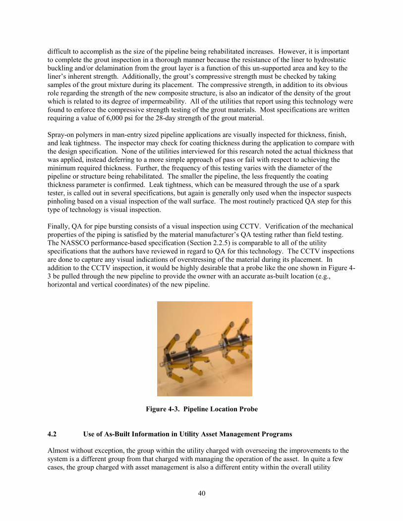
difficult to accomplish as the size of the pipeline being rehabilitated increases. However, it is important
to complete the grout inspection in a thorough manner because the resistance of the liner to hydrostatic
buckling and/or delamination from the grout layer is a function of this un-supported area and key to the
liner‟s inherent strength. Additionally, the grout‟s compressive strength must be checked by taking
samples of the grout mixture during its placement. The compressive strength, in addition to its obvious
role regarding the strength of the new composite structure, is also an indicator of the density of the grout
which is related to its degree of impermeability. All of the utilities that report using this technology were
found to enforce the compressive strength testing of the grout materials. Most specifications are written
requiring a value of 6,000 psi for the 28-day strength of the grout material.
Spray-on polymers in man-entry sized pipeline applications are visually inspected for thickness, finish,
and leak tightness. The inspector may check for coating thickness during the application to compare with
the design specification. None of the utilities interviewed for this research noted the actual thickness that
was applied, instead deferring to a more simple approach of pass or fail with respect to achieving the
minimum required thickness. Further, the frequency of this testing varies with the diameter of the
pipeline or structure being rehabilitated. The smaller the pipeline, the less frequently the coating
thickness parameter is confirmed. Leak tightness, which can be measured through the use of a spark
tester, is called out in several specifications, but again is generally only used when the inspector suspects
pinholing based on a visual inspection of the wall surface. The most routinely practiced QA step for this
type of technology is visual inspection.
Finally, QA for pipe bursting consists of a visual inspection using CCTV. Verification of the mechanical
properties of the piping is satisfied by the material manufacturer‟s QA testing rather than field testing.
The NASSCO performance-based specification (Section 2.2.5) is comparable to all of the utility
specifications that the authors have reviewed in regard to QA for this technology. The CCTV inspections
are done to capture any visual indications of overstressing of the material during its placement. In
addition to the CCTV inspection, it would be highly desirable that a probe like the one shown in Figure 4
3 be pulled through the new pipeline to provide the owner with an accurate as-built location (e.g.,
horizontal and vertical coordinates) of the new pipeline.
Figure 4-3. Pipeline Location Probe
Use of As-Built Information in Utility Asset Management Programs
Almost without exception, the group within the utility charged with overseeing the improvements to the
system is a different group from that charged with managing the operation of the asset. In quite a few
cases, the group charged with asset management is also a different entity within the overall utility
40
4.2
organizational structure. This is due in part to how the utilities have been historically structured for the
work that must be performed to add improvements, maintain those improvements, and perform other
administrative and planning work functions. This separation of key functions within the utility can lead
to challenges in the successful procurement, storage, and archiving of as-built information. Two
examples of successful integration of the functions of rehabilitation and asset management are described
below for the Little Rock Wastewater Utility in Arkansas and the City of San Diego Metropolitan
Wastewater Department in California.
Utility Case Study
Little Rock Wastewater Utility, Arkansas
An example of successful communication of as-built information across internal organizational boundaries is the Little
Rock Wastewater Utility in Arkansas. The Engineering Division advises the Maintenance Division almost immediately
when a CIPP or pipe bursting project has been completed. The maintenance division, in turn, dispatches an asset field
crew to gather the as-built information within 30 days of the project‟s completion. They will gather information on the
materials used (e.g., CIPP, HDPE, PVC, etc.) and re-confirm the surface cover, manhole top elevations, and flow-line
depths. This information is then given to their Geographic Information System (GIS) personnel who post it into the
utility‟s Arc MapTM and Hansen asset management program. The information is then used to update the pipeline‟s new
asset condition ranking using their customized ranking system. They have an in-house goal of getting this update handled
within 90 days of the rehabilitation work‟s acceptance.
41
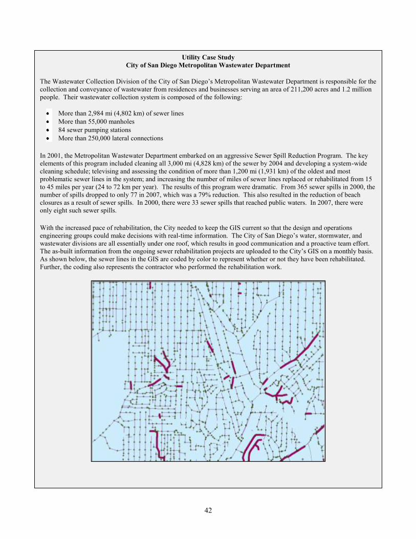
Utility Case Study
City of San Diego Metropolitan Wastewater Department
The Wastewater Collection Division of the City of San Diego‟s Metropolitan Wastewater Department is responsible for the
collection and conveyance of wastewater from residences and businesses serving an area of 211,200 acres and 1.2 million
people. Their wastewater collection system is composed of the following:
More than 2,984 mi (4,802 km) of sewer lines
More than 55,000 manholes
84 sewer pumping stations
More than 250,000 lateral connections
In 2001, the Metropolitan Wastewater Department embarked on an aggressive Sewer Spill Reduction Program. The key
elements of this program included cleaning all 3,000 mi (4,828 km) of the sewer by 2004 and developing a system-wide
cleaning schedule; televising and assessing the condition of more than 1,200 mi (1,931 km) of the oldest and most
problematic sewer lines in the system; and increasing the number of miles of sewer lines replaced or rehabilitated from 15
to 45 miles per year (24 to 72 km per year). The results of this program were dramatic. From 365 sewer spills in 2000, the
number of spills dropped to only 77 in 2007, which was a 79% reduction. This also resulted in the reduction of beach
closures as a result of sewer spills. In 2000, there were 33 sewer spills that reached public waters. In 2007, there were
only eight such sewer spills.
With the increased pace of rehabilitation, the City needed to keep the GIS current so that the design and operations
engineering groups could make decisions with real-time information. The City of San Diego‟s water, stormwater, and
wastewater divisions are all essentially under one roof, which results in good communication and a proactive team effort.
The as-built information from the ongoing sewer rehabilitation projects are uploaded to the City‟s GIS on a monthly basis.
As shown below, the sewer lines in the GIS are coded by color to represent whether or not they have been rehabilitated.
Further, the coding also represents the contractor who performed the rehabilitation work.
42
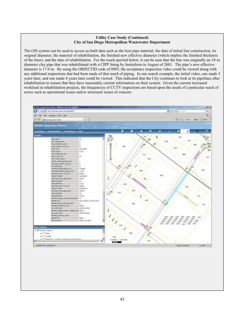
Utility Case Study (Continued)
City of San Diego Metropolitan Wastewater Department
The GIS system can be used to access as-built data such as the host pipe material, the date of initial line construction, its
original diameter, the material of rehabilitation, the finished new effective diameter (which implies the finished thickness
of the liner), and the date of rehabilitation. For the reach queried below, it can be seen that the line was originally an 18-in
diameter clay pipe that was rehabilitated with a CIPP lining by Insituform in August of 2001. The pipe‟s new effective
diameter is 17.0-in. By using the OBJECTID code of 8885, the acceptance inspection video could be viewed along with
any additional inspections that had been made of that reach of piping. In one search example, the initial video, one made 3
years later, and one made 6 years later could be viewed. This indicated that the City continues to look at its pipelines after
rehabilitation to ensure that they have reasonably current information on their system. Given the current increased
workload in rehabilitation projects, the frequencies of CCTV inspections are based upon the needs of a particular reach of
sewer such as operational issues and/or structural issues of concern.
43
4.3 Desired Use of As-Built Information and Potential Benefits from Its Collection
All of the utilities interviewed have recognized that having the as-built information kept with the asset in
an easily retrievable format strengthens their ability to view the real-time status of their wastewater
collection or water distribution system. Of the utilities interviewed, only the Little Rock Wastewater
Utility in Arkansas reported that they routinely use the as-built information gathered to set preventative
maintenance schedules, handle permitting needs, check for potential problems, and other asset
management decision-making efforts. The rehabilitation records for their pipeline segments and
appurtenances go back over 15 years, giving them a large set of historical information with which to
work. A significant downside to their current system is that recording new information about the
rehabilitated pipeline causes them to lose the historical information about the original pipeline material
(such as the date of installation). Realizing this shortcoming in their current system, they have begun
updating their asset management system to allow them to preserve this historical information, along with
recording the new work on an existing asset. The updated asset management system will also contain
improved tools to perform queries and facilitate use of this data.
It should be pointed out that as-built information goes well beyond just those changes made by a
contractor to the system during a rehabilitation project. As-built documentation should also include point
repairs made (especially when a size or shape change had to be made in the interest of time) and any other
changes made by the maintenance team. Poor management of as-built data leads to operational
inefficiency and diminished safety. With facility improvements, data that are both accurate and current
allows one to make decisions with confidence. By properly documenting facility improvements along
with the pertinent engineering data for these assets, utilities can achieve the following benefits from as-
built data collection:
Determine exactly how many items of a specific asset they own,
Identify where each asset is located,
Maintain awareness of the current structural and operational condition of each asset,
Document the rehabilitation cost, as well as the depreciated and market value for each asset,
Track how the condition of the asset has changed over time.
Having a pipeline fail due to a storm event taking out the supporting soil embedment is one thing, while
letting a pipe‟s condition decay over time through a lack of maintenance actions is an entirely different
matter. Today, utility operators know that the efficient operation of the entire system including scheduled
replacement of pipelines and appurtenant works is expected by their customers. By being proactive and
knowing the condition of their assets, the utility can schedule and coordinate all of the required
rehabilitation and maintenance-related tasks for maximum efficiency. As its financial resources become
stretched thin, there becomes an increasing need for the utility‟s efficiency in these matters.
44
5.0 RECOMMENDATIONS FOR IMPROVING QA/QC PRACTICES
A successful QA/QC program is one that measures the finished installation in terms of the desired and/or
required long-term performance requirements. This means tailoring the QA/QC program to be
technology-specific and considering its role in the new soil-structure interaction system that is created by
the improvements. Integral to this effort, the design engineer must make the requisite review of the
current pipeline or structure‟s as-built information and current condition assessment. Parameters
affecting the service life of the proposed improvements such as hydrostatic buckling forces must be
properly investigated and communicated in the contract documents. Site-specific issues related to the
local soils, past repairs, etc. must be accurately conveyed to the installation contractor.
In current practice, the project specifications reviewed typically followed the proprietary QA
recommendations supplied by the vendor for the technologies being used on the project (see Section 2).
Depending on the level of experience of the engineer and the owner with the chosen technologies, these
recommendations were either placed in a prescriptive-based format or a performance-based format.
Although often included in the project specifications, the physical testing requirements of the QA/QC
program were found to be in limited use by most utilities. Construction observation also varied widely
from full-time, to very intermittent, to not at all. In most cases, a great deal of emphasis has been placed
on the final CCTV inspection to determine the finished quality of the installed improvements.
Overall, the interviews indicated that both vendors and utilities tend to value having a QA/QC program
associated with rehabilitation projects. However, depending upon the available resources (both funding
and manpower) at the time the project is carried out, the actual execution of the QA/QC steps may vary in
the field. The more utilities cut back on the execution of their QA/QC program, the greater the risk that
some installers may work only to produce a “good looking installation.” This is not a good formula for
achieving long-life for rehabilitated installations. One observation is that too much emphasis is placed
upon the final CCTV video inspection of which the quality for a large percentage of these videos is
insufficient to detect defects in the installation.
Based upon a review of the current QA/QC practices in use and considering the future needs of well-
constructed asset management programs, the following recommendations were developed for a best
practice QA/QC system listed by technology.
5.1 Technology Specific Recommendations for QA/QC Best Practices
5.1.1 CIPP Best Practices Recommendations. The steps involved in a best practice for QA/QC
of CIPP technology installations are as follows:
During the design phase of the project, confirm the as-built and current condition of the pipe
to be rehabilitated with the following minimum pieces of information: 1) type of material; 2)
diameter and/or geometry; 3) estimated hydrostatic loading and duration based upon field
investigation; 4) maintenance crew experiences; 5) United States Geological Survey (USGS)
National Water Information System (NWIS) groundwater data reports; 6) estimated condition
and future performance of the existing pipeline‟s embedment material; and 7)
characterization of the flow carried by the existing pipeline (Pennington et al., 2008).
A pre-lining CCTV should be conducted to assess the current pipe condition and to
investigate the line for obstructions that would prevent liner insertion such as offset joints,
protruding service connections, or collapsed pipe sections. Point repairs may be needed to
address any identified obstructions.
45
Use a performance-based specification written to convey the end goals of the rehabilitation
effort and the testing that will be employed to confirm that those end goals have been
achieved.
Use an inspector that has been trained in the technology and has been thoroughly briefed on
the project‟s performance goals and technology-specific specifications. The inspector should
perform the following activities during the construction observation phase for CIPP projects:
o Upon arrival of the saturated tubes on the project site, require tube-specific saturation
logs to confirm a full saturation was made based upon the earlier submittals; if not, reject
any tube suspected of containing less than 97% of the manufacturer‟s recommended
quantity of resin from being installed.
o Require an in situ cured sample for each installation performed, including UV light cured
installations. Restrained samples should come from an intermediate manhole if possible.
Measure the finished thickness of the liner in place using a non-destructive testing gage
such as an ultrasonic thickness gage.
o Review results of the cured sample testing. The sample testing should include verifying
the flexural modulus, the flexural strength, and the tensile strength. If elongation at break
during the tensile strength testing (ASTM D638) is larger than that stated for the resin
material per its technical data sheet (TDS), require additional testing to verify that the
proper amount of resin is present in the liner and that the porosity of the installed liner is
in keeping with the specified water tightness performance expectation in the contract
documents.
o Require that the post-installation CCTV inspection be conducted with the camera at the
approximate center of the pipeline, while traveling no faster than 30 ft per min (9.1 m per
min) with adequate lighting and no water in the invert to allow for a full 360 view of the
finished liner. Blemishes in the coating and other deviations from an ideal installation
should be given a thorough documentation by the camera operator.
The project engineer should review the construction observation documentation with the
project inspector and certify that the work was performed to the standards set forth in the
project specifications (Stinson and Struzziery, 2007).
A CCTV inspection should be conducted by the asset management team to code the condition
of the rehabilitated pipeline in a standardized format and update the utility‟s asset database as
soon as is practical after the project is accepted. A follow-up inspection should also be made
30 to 60 days prior to the end of the installation warranty period again coding the new
pipeline‟s condition so that any construction-related defects not found with the above steps
can be identified and scheduled for repair under warranty by the contractor.
5.1.2 Close Fit Liner Systems Best Practices Recommendations. Close fit liner systems are
promoted as being relatively easy to install and less vulnerable to deviations in their installed mechanical
properties as they are manufactured in a controlled plant environment. The following steps are
recommendations of a best practice for the QA/QC of close fit liner installations:
During the design phase of the project, confirm the as-built and current condition of the pipe
to be rehabilitated with the following minimum pieces of information: 1) type of material; 2)
diameter and/or geometry; 3) estimated hydrostatic loading and duration thereof based upon
field investigation; 4) maintenance crew experiences; 5) USGS NWIS groundwater data
reports; 6) estimated condition and future performance of the existing pipeline‟s embedment
material; and 7) characterization of the flow carried by the existing pipeline.
46
Conduct a CCTV inspection to verify that the pipe is ready to receive the lining, to note if
there are any pipe openings not detected, to see if there are any protruding services or other
defects that would preclude lining, to track the location of service connections to be renewed.
Use a performance-based specification written to convey the end goals of the rehabilitation
effort and the testing that will be employed to confirm that those end goals have been
achieved.
Use an inspector that has been trained in the technology and has been thoroughly briefed on
the project‟s performance goals and technology-specific specifications. The inspector should
perform the following activities during the construction observation phase for close fit lining
projects:
o Upon arrival of the lining materials on the project site, the inspector should confirm that
the materials have the required markings identifying them as the correct materials and
that they are of the correct thickness.
o Require that an in situ sample be made during the processing of each installation using a
mold of like diameter.
o Have the sample tested to verify the following:
Thickness includes looking for areas of uneven stretching
Mechanical properties (should match those performed at the time of manufacture)
No residual stresses are present (perform an oven test on a ring of the reformed
material to ensure that the liner stays round and is dimensionally stable as specified
in ASTM F1057 Practice for Estimating the Quality of Extruded Poly (Vinyl
Chloride) (PVC)Pipe by the Heat Reversion Technique).
o Require that a post-installation CCTV inspection be made with the camera at the center
of the pipeline, while traveling no faster than 30 ft per min (9.1 m per min) with adequate
lighting and no water in the invert to allow for a full 360 view of the finished liner.
Excessive local stretching and poor fit at the lateral connections (not tight with the host
pipe) should be given a thorough review and visual documentation by the camera
operator.
The project engineer should review the construction observation documentation with the
project inspector and certify that the work was performed to the standards set forth in the
project specifications.
A CCTV inspection should be conducted by the asset management team to code the condition
of the rehabilitated pipeline in a standardized format and update the utility‟s asset database as
soon as is practical after the project is accepted. A follow-up inspection should also be made
30 to 60 days prior to the end of the installation warranty period again coding the new
pipeline‟s condition, so that any construction-related defects not discovered with the above
steps can be identified and scheduled for repair under warranty by the contractor.
5.1.3 Sprayed-on Polymeric Coating Best Practices Recommendations. The recommended best
practices for QA/QC of a sprayed-on polymeric coating system are as follows:
During the design phase of the project, confirm the as-built and current condition of the pipe
to be rehabilitated with the following minimum pieces of information: 1) type of material; 2)
diameter and/or geometry; 3) estimated hydrostatic loading and duration thereof based upon
field investigation; 4) maintenance crew experiences; 5) USGS NWIS groundwater data
reports; 6) estimated condition and future performance of the existing pipeline‟s embedment
material; and 7) characterization of the flow carried by the existing pipeline.
47
Use a performance-based specification written to convey the end goals of the rehabilitation
effort and the testing that will be employed to confirm that those end goals have been
achieved.
Use an inspector that has been trained in the technology and has been thoroughly briefed on
the project‟s performance goals and technology-specific specifications. The inspector should
perform the following activities during the construction observation phase for sprayed-on
coating projects:
o Upon arrival of the raw materials on the project site, review the products‟ labeling to
ensure that the correct products have been delivered.
o Prior to commencing work, review with the project superintendent the proposed
methodology for cleaning and preparing the pipe wall for lining. This will be dependent
upon the existing pipeline‟s material and the current condition of the wall structure. The
pipe wall must be completely dry and competent (solid) to accept the lining material and
achieve the proper adherence between the polymer and the host pipe material.
o Conduct a CCTV inspection of the pipeline to verify that there is no standing water and
the pipe is suitably free of debris just prior to applying the polymeric coating.
o Require the contractor to prepare samples in a manner consistent with the application
technique being used. Curing should be done in the same environment in which the
lining will be cured.
o Review results of the cured sample testing. The sample should be tested for bond
strength, mechanical properties, and porosity. In situ thickness should also be measured
using an ultrasonic thickness gage calibrated for the particular polymeric material being
applied.
o Require that the post-installation for non man-entry size piping CCTV inspection be
conducted with the camera at the approximate center of the pipeline, while traveling no
faster than 30 ft per min (9.1 m per min) with adequate lighting and no water in the invert
to allow for a full 360 view of the finished liner. Blemishes in the coating and other
deviations from an ideal installation should be given a thorough review by the camera.
For man-entry size piping, the inspection should also include still photos of questionable
areas.
The project engineer should review the construction observation documentation with the
project inspector and certify that the work was performed to the performance standards set
forth in the project specifications.
A CCTV inspection should be conducted by the asset management team to code the condition
of the rehabilitated pipeline in a standardized format and update the utility‟s asset database as
soon as is practical after the project has been accepted. A follow-up inspection should also be
made 30 to 60 days prior to the end of the installation warranty period - again coding the new
pipeline‟s condition so that any construction related defects not discovered with the above
steps can be identified and scheduled for repair under warranty by the contractor.
5.1.4 GIPL Best Practices Recommendations. The recommended best practices for QA/QC of a
GIPL system are as follows:
During the design phase of the project, confirm the as-built and current condition of the pipe
and/or structures to be rehabilitated with the following minimum pieces of information: 1)
type of material; 2) diameter and/or geometry; 3) estimated hydrostatic loading and duration
thereof based upon field investigation; 4) maintenance crew experiences; 5) USGS NWIS
48
groundwater data reports; 6) estimated condition and future performance of the existing
pipeline or structure‟s embedment material; and 7) characterization of the flows carried by
the existing pipeline and environmental conditions in the structures.
Use a performance-based specification written to convey the end goals of the rehabilitation
effort and the testing that will be employed to confirm that those end goals have been
achieved.
Use an inspector that has been trained in the technology to be used and has been thoroughly
briefed on the project‟s performance goals and technology-specific specifications. The
inspector should perform the following activities during the construction observation phase
for GIPL projects:
o Upon arrival of the lining materials on the project site, review the products‟ labeling to
ensure that the correct products have been delivered and that they are free from defects.
o Prior to commencing work, review with the project superintendent the proposed
methodology for cleaning and preparing the pipe wall for lining. This will be dependent
upon the existing pipeline‟s material and the current condition of the wall structure. The
pipe wall should be clean with no active leaks that will affect the grout placement. The
host pipe‟s wall should be competent to accept the grout and achieve the proper
interaction between the thermoplastic liner and the host pipe material.
o Require a visual confirmation of the existing pipeline‟s condition just prior to installation
of the lining.
o Once the lining material is in place, the grouting operation should be carried out in lifts
per the technology manufacturer‟s recommendations. Samples of the grout mixture
should be taken at regular intervals throughout the grout‟s placement. Curing of grout
samples should be done in the host pipe‟s environment or similar conditions.
o Review results of the cured grout sample testing. The sample should be tested for
compressive strength. Additionally, the entire length of the installation should be
evaluated for the presence of voids in the grout zone. At a minimum, this should be done
by “sounding” the liner surface with a small hammer; other non-destructive techniques
such as ultrasonic testing should be used as they become available. Void areas greater
than 5% of the circumference should be spot grouted.
o Require that the post-installation CCTV inspection be conducted with the camera at the
approximate center of the pipeline, while traveling no faster than 30 ft per min (9.1 m per
min) with adequate lighting and no water in the invert to allow for a full 360 view of the
finished liner. Blemishes in the liner and other deviations from an ideal installation
should be given a thorough documentation by the camera operator.
The project engineer should review the construction observation documentation with the
project inspector and certify that the work was performed to the performance standards set
forth in the project specifications.
A CCTV inspection should be conducted by the asset management team to code the condition
of the rehabilitated pipeline in a standardized format and update the utility‟s asset database.
A follow-up inspection should also be made 30 to 60 days prior to the end of the installation
warranty period again coding the new pipeline‟s condition so that any construction-related
defects not discovered with the above steps can be identified and scheduled for repair by the
contractor.
49

5.1.5 Pipe Bursting Best Practices Recommendations. The recommended best practices for
QA/QC of a pipe bursting project are as follows:
During the design phase of the project, confirm the as-built and current condition of the pipe
to be rehabilitated with the following minimum pieces of information: 1) type of material; 2)
diameter and/or geometry; 3) estimated hydrostatic loading and duration thereof based upon
field investigation; 4) maintenance crew experiences; 5) USGS NWIS groundwater data
reports; 6) estimated condition and future performance of the existing pipeline‟s embedment
material (including its classification and the native soil‟s classification if different); 7) a
current video of the existing pipeline condition (including information on sags); and 8)
identification of other piping within the proposed work disturbance zone.
Use a performance-based specification written to convey the end goals of the rehabilitation
effort and the testing that will be employed to confirm those end goals have been achieved.
An industry written performance-based specification guideline on pipe bursting is available
from NASSCO.
Use an inspector that has been trained in the technology and has been thoroughly briefed on
the project‟s performance goals and technology-specific specifications. The inspector should
perform the following activities during the construction observation phase for pipe bursting
projects:
o Upon arrival of the raw materials on the project site, review the products‟ labeling to
ensure that the correct products have been delivered and that they are free from defects.
o Prior to commencing work, review with the project superintendent the proposed
construction sequence and methodology for reconnecting the service laterals. Note that
this will be somewhat dependent upon the existing pipeline‟s material and how much
upsizing (if any) is planned for the project.
o Conduct a CCTV inspection of the pipe to verify that the diameter is consistent, that there
are no unanticipated pipe bends or dips in the pipe and track location of connections.
o During the bursting and pulling in of the new pipeline, the inspector should observe that
the lengths of pipe are joined properly by butt fusion (where fused pipe is employed) and
that no portion of the piping has a gash, blister, abrasion, nick, scar or other deleterious
fault greater in depth than 10% of the pipe‟s thickness. (Note: For pipes expected to
perform under significant internal pressure, the control of scratches and gouges is much
more important and should be more restrictive.)
o Require that a post-installation CCTV inspection be conducted with the camera at the
approximate center of the pipeline while traveling no faster than 30 ft per min (9.1 m per
min) with adequate lighting and no water in the invert to allow for a full 360 view of the
finished liner. Blemishes in the pipe wall and other deviations from an ideal installation
should be given a thorough documentation by the camera operator.
The project engineer should review the construction observation documentation with the
project inspector and certify that the work was performed to the performance standards set
forth in the project specifications.
A follow-up CCTV inspection should also be made 30 to 60 days prior to the end of the
installation warranty period - again coding the new pipeline‟s condition so that any
construction related defects not discovered with the above steps can be identified and
scheduled for repair by the contractor.
50
5.2 Encouraging and Achieving the Owner’s Implementation of Best Practice
Methodologies
The rehabilitation of pipelines generally does not carry the same sense of importance for construction
observation and as-built documentation when compared to new construction. In addition, it doesn‟t
afford the same opportunity for construction observation because access is often limited by nature for
trenchless rehabilitation technologies to the ends of the pipe or a few access pits. This may discourage
utilities from undertaking rehabilitation technologies even if they may cost less.
Better recognition is needed among utilities and vendors that trenchless rehabilitation technologies are
part of a comprehensive re-building program for pipelines and structures. As utilities become aware of
the benefits of more extensive data collection in the field and consistent documentation of as-built data,
their focus on developing and maintaining successful QA/QC programs will increase. Based on the
available information obtained from utility and vendor interviews and engineering judgment, several
recommendations were made for improving testing and QA/QC practices for rehabilitation technologies.
Technology-specific QA/QC best practices were summarized in the previous sections and general steps to
encourage the use of these best practices are as follows:
Development of Protocols for Retrospective Evaluation of Rehabilitation Technologies. The
biggest data gap in asset management involving rehabilitation is the prediction of remaining
asset life and determining how long rehabilitation techniques can extend that life.
Municipalities have expressed a strong desire for some hard data on the current condition of
previously installed systems in order to validate or correct the assumptions made at the time
of rehabilitation. The development of an appropriate protocol for a retrospective look at the
performance of CIPP and its in-service performance has been added to the scope of the
current US EPA research into aging water infrastructure. This investigation and testing
program should yield a preliminary report card on how well the execution of existing QA/QC
programs have delivered on the anticipated design life of the installed improvements and will
be a good first step in supporting implementation of the aforementioned best practices for
CIPP. The outcome of the research will be a retrospective evaluation protocol for CIPP
materials testing and a database template developed with example results based on two CIPP
case studies. The intent of the report and initial database template is to show the value of
such data collection and to provide a road map for how a consistent database of quantitative
performance information can be assembled by utility owners. The protocol could also be
modified to examine the baseline and long-term performance of additional trenchless
rehabilitation technologies. Utilities could then benefit from the widespread use of these
retrospective protocols by tracking the performance of rehabilitated assets over time to
determine if rehabilitation efforts have resulted in a good investment and are likely to last up
to or beyond their design life.
Standardized Approaches for Long-Term Performance Testing of Trenchless Technologies.
One key difference that was identified between European and North American practices was
the lack of a standardized approach to long-term performance testing for trenchless
technologies. The ASTM standard installation practice and materials specification
documents do not provide definitive guidance on testing to verify the long-term mechanical
characteristics of critical relevance to trenchless technology design. In the US, these values
are typically obtained from the manufacturers‟ literature and are commonly taken as 50% of
the short-term characteristics determined in accordance with the specifications rather than
actual 10,000 hour testing (although ASTM D5813 for CIPP does require 10,000 hour
testing, the standards associated with other materials do not).
51
Broader Setting of Standards by ASTM, AWWA, and Other Organizations. The existence of
standardized approaches to QA/QC is limited due primarily to the proprietary nature of new
and emerging rehabilitation technologies. As the governing patents expire on many aspects
of these rehabilitation technologies, more companies are encouraged to enter the marketplace
and compete with the established technology providers. As use of these technologies widen,
it is important that standardized QA/QC procedures are in place and used effectively - both to
provide for a high performance and long-lasting product and also to allow contractors who
provide quality to compete fairly in the marketplace. ASTM, AWWA, and other
organizations can encourage the development of a broader set of standards to improve the
installation practices for key technologies.
Improved Training Programs to Encourage Good QA/QC Practices. The second step to
encouraging the development and implementation of a QA/QC program is educating owners
and their engineers in the specific requirements of innovative and conventional rehabilitation
technologies and to provide an overview of lessons learned to enhance the effectiveness of
construction observation during installation. Owners and engineers may be less reluctant to
take a strong stance regarding their stated QA/QC requirements if they are more confident in
their understanding of innovative rehabilitation technologies and the associated
specifications. This training leads to realistic expectations of the finished look of the
improvements and in-place performance expectations (e.g., hydraulic, structural, leak-
tightness, etc.) and reinforces the need to ensure the quality of installations. Several
organizations such as the North American Society for Trenchless Technology (NASTT) and
NASSCO are undertaking efforts to improve QA/QC practices and to address knowledge
gaps related to rehabilitation technologies through training programs. NASTT has developed
a series of 1-day training seminars regarding good practices related to the design and
construction observation of several of trenchless technologies including CIPP, pipe bursting,
and horizontal directional drilling (HDD). NASSCO has embarked on a more in-depth series
of training classes for the construction observation phase of these technologies such as a two-
day course for CIPP taught by instructors with in-depth knowledge of CIPP‟s proper
installation and quality installation practices. In 2010, NASSCO is developing training
courses for pipe bursting and manhole rehabilitation.
Increased Construction Observation by Owners and Owner‟s Representatives and Timely
Documentation of As-Built Condition. The rehabilitation of pipelines generally does not
carry the same sense of importance for construction observation when compared to new
construction. To the extent possible, utilities should implement the following: 1) full-time
construction observation for rehabilitation projects; 2) coding of the as-built condition of the
improvements shortly after installation to establish a baseline for the renewed asset; and 3)
timely documentation of the as-built condition into the asset management system, while
making provisions for updates as needed to ensure that future changes in condition are
captured and quantified. Material testing results and other QA/QC data should be archived
for long-term record keeping for future reference of baseline conditions.
Increased Use of Standardized Coding to Document Installed Condition. Coupled with the
above changes, improvements to pipeline condition assessment in the areas of standardizing
the coding and making the data entry process easier for the input, transfer, and use of data in
asset management software will further reinforce for owners the value of good QA/QC
practices. For wastewater utilities, programs such as NASSCO‟s PACP encourage vendors
and engineers to create tools that make greater use of their condition assessment data. A
similar more uniform approach for the condition assessment of water mains (both
deteriorated and newly rehabilitated) could be developed.
52

Improved Record-Keeping and Asset Management. Recent improvements in asset
management software allow owners to accomplish several critical tasks including asset
inventory and GIS integration, maintenance planning and scheduling, condition assessment,
risk assessment, capacity assessment, and work flow management. This software can be
especially powerful when you can visualize results. For example, owners were identified in
this review that had software to easily show the location of rehabilitated stretches of their
network. Key information about the project could be rapidly linked in with the pre- and post-
rehabilitation CCTV and other relevant rehabilitated pipe data. However, some care needed
to be taken not to lose historic data with subsequent updates. Without organized digital
information to cover both historical and current data, most projects will require weeks of
work to come up with the results necessary to make good asset management decisions. This
becomes even more difficult if one wishes to combine historical information (such as risk
assessment) with future efforts (such as work management to create an inspection plan).
Asset management software provides insight into the critical balance between the level of
service, risk management, and life cycle costs. Smaller-scale systems exist that handle a few
of these items very well such as Check-Up Program for Small Systems (CUPPS) provided by
the US EPA for small water and wastewater utilities. Many asset owners aspire to make the
transition from simple condition assessment to more evolved risk assessment and decision
support processes in order to base their rehabilitation decisions on well-formed data. Asset
management software can provide this link.
53
6.0 REFERENCES
Allouche, E. and G. Shanghai. 2008. “The Design and Performance of Pressure Pipe Liners under Static
and Cyclical Loading.” Proceedings of the American Society of Civil Engineers (ASCE) Annual
Pipelines Conference: Maximizing Performance of Our Pipeline Infrastructure, Atlanta, Georgia,
July 22-27, 2008.
Ampiah, N., A. Fam, and I. Moore. 2008. “Wavy Imperfections and the Strength of Cast-In-Place
Pressure Pipe Liners.” Proceedings of the ASCE Annual Pipelines Conference: Maximizing
Performance of Our Pipeline Infrastructure, Atlanta, Georgia, July 22-27, 2008.
Carpenter. 2009. “12th Annual Municipal Survey,” Underground Construction, Vol. 64 No. 2, February
2009, Oildom Publishers, Houston TX.
City of Columbus Division of Sewerage and Drainage. 2007. Rule and Regulation Number PN0200
2007: Evaluation and Approval of Sewerage and Drainage New Sewer Collection System
Products.
European Union Standard EN 13566:2002. Plastics Piping Systems for Renovation of Underground Non-
Pressure Drainage and Sewerage Networks.
Gumbel, J. 1998. “Review of Principles, Practice, and Current Developments Worldwide.” Proceedings
of the ASCE Annual Pipelines Conference.
Guy, H. 2007. “Design-Build and Trenchless.” Proceedings of the ASCE Annual Pipelines Conference:
Advances and Experiences with Trenchless Pipeline Projects, Boston, Massachusetts, July 8-11,
2007.
Hu, Y, D. Wang, S. Baker, and K. Cossitt. 2009. “AC Pipe in North America: Rehabilitation /
Replacement Methods and Current Practices.” Proceedings of the ASCE Annual Pipelines
Conference: Infrastructure‟s Hidden Assets, San Diego, CA, August 15-22, 2009.
Husselbee, B. 2009. Personal Communication. Types of QA/QC documentation collected for trenchless
technology projects.
IKT. 2008. IKT Liner Report: Tube Liner Quality in 2007, An Improvement Over Last Year.
http://www.ikt.de/down.php?f=22&lang=english.
Joint Cooperative Committee of the Southern California Chapter. 2009. Greenbook: Standard
Specifications for Public Works Construction. BNI Publications, Inc.
Kampbell, E. and L. Whittle. 2003. “QA/QC for Close-Fit Pipeline Renewal.” Proceedings of the ASCE
Annual Pipelines Conference: New Pipeline Technologies, Security, and Safety, Baltimore,
Maryland, July 13-16, 2003.
Kurz, G., D. Bible, and G. Ballard. 2004. “Nashville’s Performance-Based Sewer Rehabilitation
Progress.” Proceedings of No-Dig 2004 Conference, NASTT, New Orleans, Louisiana, March
22-24, 2004.
54
NASSCO. 2009. Guideline Specification for the Replacement of Mainline Sewer Pipes by Pipe Bursting.
http://www.nassco.org/publications/specs/spec_guidelines/pipebursting-ipba.pdf.
Orton, C. 2007. “Lessons Learned from Large Diameter Sanitary Sewer Pipe Bursting Project:
Conversion of Abandoned Gravity Sewer Main into Upsized Sanitary Force Main South San
Francisco, CA.” Proceedings of the ASCE Annual Pipelines Conference: Advances and
Experiences with Trenchless Pipeline Projects, Boston, Massachusetts, July 8-11, 2007.
Pennington, R., K. Gersley, and A. Gagliostro. 2008. “A Proactive Approach to the Rehabilitation of an
Aging Brick Sewer Infrastructure in Newark, New Jersey.” Proceedings of the ASCE Annual
Pipelines Conference: Maximizing Performance of Our Pipeline Infrastructure, Atlanta, Georgia,
July 22-27, 2008.
Rush, J. 2006. “Whites Creek Performance-Based I/I Reduction Project.” Trenchless Technology
Magazine, October.
Steward, E., E. Allouche, M. Baumert, and J. Gordon. 2009. “Testing of Rigid Polyurethane Spray-On
Lining under Internal Pressure.” Proceedings of the ASCE Annual Pipelines Conference:
Infrastructure‟s Hidden Assets, San Diego, CA, August 15 - 22, 2009.
Stinson, T. and J. Struzziery. 2007. “Lessons Learned –Lining Asbestos Cement Sewer Main.”
Proceedings of the ASCE Annual Pipelines Conference: Advances and Experiences with
Trenchless Pipeline Projects, Boston, Massachusetts, July 8-11, 2007.
Zhao, W. and L. Whittle. 2009. “An Asset Management Definition of Pipe Rehabilitation Success or
Failure.” Proceedings of the ASCE Annual Pipelines Conference: Infrastructure‟s Hidden Assets,
San Diego, CA, August 15 - 22, 2009.
55