Embed Size (px)
Citation preview
Q192 Generation Interconnection
Interconnection Facilities Study Results
APS Contract No. 52750
By
Arizona Public Service Company Transmission Planning
May 5, 2014
Version 1.0

Q192 Facilities Study APS Contract No. 52750
Page i
Q192 FACILITIES STUDY
TABLE OF CONTENTS
Contents 1. Introduction ............................................................................................................................................ 1
2. Q192 INTERCONNECTION FACILITIES .............................................................................................. 4
3. CONSTRUCTION ESTIMATES ............................................................................................................ 5
3.1. Summary of High Level Cost Estimate for SGIA Facilities ........................................................... 6
3.2. Summary of Construction Time Estimates at the POI .................................................................. 7
4. REQUEST FOR TRANSMISSION SERVICE........................................................................................ 9
5. POWER FACTOR REQUIREMENTS ................................................................................................... 9
5.1 Reactive Support .......................................................................................................................... 9
Q192 Facilities Study APS Contract No. 52750
Page ii
List of Acronyms ACC Arizona Corporation Commission ACSS Aluminum Conductor Steel Supported ANPP Arizona Nuclear Power Project APS Arizona Public Service ATC Available Transfer Capability CAISO California Independent System Operator Corporation CAWCD Central Arizona Water Conservation District CCVT Coupling Capacitor Voltage Transformer COD Commercial Operation Date CSP Concentrated Solar Power CT Combustion Turbine or Current Transformer EPE El Paso Electric ER Energy Resource ERIS Energy Resource Interconnection Service FaS Facilities Study FERC Federal Energy Regulatory Commission FeS Feasibility Study GT Gas Turbine IC Interconnection Customer IID Imperial Irrigation District IR Interconnection Request LADWP Los Angeles Department of Water and Power LGIA Large Generator Interconnection Agreement NEC Navopache Electric Cooperative NERC North American Electric Reliability Corporation NR Network Resource NRIS Network Resource Interconnection Service NTUA Navajo Tribal Utility Authority OASIS Open Access Same Time Information System OATT Open Access Transmission Tariff PG&E Pacific Gas & Electric PNM Public Service Company of New Mexico POI Point Of Interconnection PPA Purchase Power Agreement PSLF/PSDS/SCSC Positive Sequence Load Flow/Positive Sequence Dynamic
Simulation/Short-Circuit Saturation Curve PST Phase-Shifting Transformer PV Photovoltaic RAS Remedial Action Scheme (also known as SPS) RFP Request for Proposal SCE Southern California Edison Company SDG&E San Diego Gas & Electric Company SIS System Impact Study SLG fault Single Line-to-Ground fault SPS Special Protection System (also known as RAS) SRP Salt River Project SSVEC Sulphur Springs Valley Electric Cooperative, Inc. SVC Static VAR Compensator SVD Static VAR Device SWTC Southwest Transmission Cooperative TEP Tucson Electric Power TPIF Transmission Provider’s Interconnection Facilities WAPA Western Area Power Administration WECC Western Electricity Coordinating Council

Q192 Facilities Study APS Contract No. 52750
Page 1
1. Introduction Arizona Public Service Company (APS) performed this Generator Interconnection Facilities Study (FaS) in response to a 20 MW solar interconnection request by the Interconnection Customer (IC). The Customer is listed in APS’s Active Generator Interconnection Queue as queue number 192 (Q192). The purpose of the study is to provide cost and construction schedule estimates for the facilities needed to interconnect the IC’s proposed 20 MW solar generation facility located approximately twenty (20) miles south of the town of Buckeye in Maricopa County, Arizona. The IC has requested interconnection into the Komatke 69 kV switchyard (formerly known as the Jojoba 69kV substation). The Point of Interconnection (POI) for this project will therefore be at the Komatke 69 kV switchyard. The Interconnection Customer submitted an interconnection request to APS, which was accepted on March 24, 2011 and has already completed a System Impact Study. This Project is a FERC jurisdictional small generator interconnection request. The Intetrconnection Customer’s original requested In-Service date, as indicated in the application, was May 1, 2013. The Interconnection Customer submitted a revised requested Commercial Operation Date, as per the Facilities Study Agreement for Q192 for June 30, 2017. Additionally, the Interconnection Customer’s requested date to have the interconnection initially energized in order to take back feed power is March 15, 2017. APS anticipates having the Komatke 69 kV switchyard energized in December of 2016; therefore, the Interconnection Customer’s requested Commercial Operation Date of June 30, 2017 can be met. Please note that the Commercial Operation Date must be within the seven (7) years of the APS acceptance of the Interconnection Customer’s Interconnection Request. All reasonable efforts will be used by APS to meet the Interconnection Customer’s proposed project dates. The Interconnection Customer’s project will interconnect with the APS Transmission System as an Energy Resource Interconnection Service. Delivery of the Q192 output beyond the POI would be on an “as-available” basis only. The delivery of the Q192 output would be subject to the firm or non-firm transmission capacity that may be available when a Transmission Service Request is made. Figure 1 shows a general location of Q192, as well as a general depiction of the subtransmission system around Q192’s proposed POI. The Interconnection Customer will be responsible to construct, own and operate the 69kV line from the Q192 generation station up to and including the last pole before the APS substation fence, also known as the Point of Change of Ownership. APS will be responsible for taking the 69kV line from that pole and into the 69kV bus, shown as Transmission Provider’s Interconnection Facilities. The build-out of the Q192 project’s interconnection facilities are depicted in a simple one-line diagram in Figure 2.

Q192 Facilities Study APS Contract No. 52750
Page 2
Figure 1. Project Location & Transmsission System in the Q192 Vicinity

Q192 Facilities Study APS Contract No. 52750
Page 3
Figure 2. New Q192 Switchyard one-line
Q192 Facilities Study APS Contract No. 52750
Page 4
Disclaimer Nothing in this report constitutes an offer of transmission service or confers upon the Interconnection Customer (“IC”) any right to receive transmission service. APS and other interconnected utilities may not have the Available Transmission Capacity to support the interconnection described in this report. It should also be noted that all results for the FAS are highly dependent upon the assumed topology and timing of new projects in the vicinity of the interconnection, which are subject to change.
2. Q192 INTERCONNECTION FACILITIES An Interconnection Customer owned visibly-open Disconnect Device equipped with grounding provisions acceptable to APS; and system protection facilities is required. The Interconnection Customer will be responsible for a monthly Direct Assignment Charge (“DAC”) that covers the cost of Operations and Maintenance of the line extensions and its associated equipment. After construction of the required line extension and supporting facilities, the DAC will be identified and charged monthly to the Customer based on the actual cost of construction. The actual-cost-based DAC will be a fixed monthly charge for the life of the FERC Interconnection Agreement beginning on the In-Service Date. Replacement of failed equipment, at actual cost, is at Interconnection Customer’s expense and invoiced by APS. (a) Description of Transmission Provider's Interconnection Facilities: The communication cost estimate required for the Q192 project includes equipment as well as work estimates to construct, install and/or terminate the fiber optic line(s) from the Q192 site to the Komatke switchyard and into the APS ECC, and perhaps to a second substation for a “transfer-trip relay scheme”. APS will construct, own and operate the facilities in the Komatke switchyard and the portion of 69 kV line from the Komatke 69 kV bus up to the first structure outside the switchyard fence. The Interconnection Customer will construct, own and maintain the 69 kV generation tie-line from the first structure outside the switchyard fence to the Q192 site. The estimate for this portion of line includes work for site preparation, including above grade and below grade; foundations; conduits; grounding; 69 kV PTs; 69 kV CTs and 69 kV switches; structures; bi-directional metering equipment; and RTUs. (b) Description of Network Upgrades: There is one type of upgrade associated with this Project: Network Upgrades. Network Upgrades only apply to some upgrades to the system at or above 69kV. Network Upgrades do not include Distribution Upgrades. Theses upgrades are defined by FERC as:
Distribution Upgrades—The additions, modifications, and upgrades to the Transmission Provider’s Distribution System required at or beyond the Point of Interconnection to facilitate interconnection of the Small Generating Facility and render the transmission service necessary to effect the Interconnection Customer’s wholesale sale of electricity in interstate commerce. Distribution Upgrades do not include Interconnection Facilities. Network Upgrades—The additions, modifications, and upgrades to the Transmission Provider’s Transmission System required at or beyond the point at which the Small Generating Facility Interconnects with the Transmission Provider’s Transmission System to accommodate the interconnection with the Small Generating Facility to the Transmission Provider’s Transmission System. Network Upgrades do not include Distribution Upgrades. Stand Alone Network Upgrades—The Network Upgrades that an Interconnection Customer may construct without affecting day-to-day operations of the Transmission System during their
Q192 Facilities Study APS Contract No. 52750
Page 5
construction. Both the Transmission Provider and the Interconnection Customer must agree as to what constitutes Stand Along Network Upgrades and identify them in Appendix A to the Standard Large Generator Interconnection Agreement.
Network Upgrades are typically repaid by APS via transmission service credits over a twenty year period. Any amount remaining at the end of the twenty years, if any, are repaid to the Interconnection Customer, including such interest as defined by FERC. APS estimates the following with regards to Network Upgrades:
• Construction of a new 69 kV bay for Q192 at the Komatke switchyard; o One 69kV breaker o Steel structures
Figure 2 is a one-line diagram of the proposed configuration and interconnection of Q192’s Project. In Figure 2, the facilities shown in black are the APS planned facilities. In Figure 2, the facilities shown in blue are the Network Upgrades. In Figure 2, the facilities shown in red are the Transmission Provider’s Interconnection Facilities (TPIF). The TPIF includes the portion of the 69 kV gen-tie line that is within the Komatke switchyard fence. APS will own, operate, and maintain the portion of that line from the 69 kV bus up to the first structure outside of the substation fence, at which point the Interconnection Customer would pick-up ownership and responsibility for the line.
3. CONSTRUCTION ESTIMATES The desired in-service date to provide back feed power for the IC’s interconnection facilities is Marchl 15, 2017. The estimated cost of the Q192 interconnection is allocated into the following categories: Network Upgrades and Transmission Provider’s Interconnection Facilities; and is summarized in Table 1 below. Construction schedule estimates are from the date the Interconnection Customer provides written authorization to proceed, provided all interconnection agreements and funding arrangements are in place. Interconnection construction costs and timelines were estimated for Q192 based on the location described in the IC’s Interconnection Appliacation. These good faith non-binding cost estimates are applicable only to the APS system. This study reviewed all capacity, construction, flicker, protection and communications requirements to interconnect this “FERC” generation project. NERC (North American Reliability Corporation) requires that generation facilities provide a primary and secondary (back-up) communications path for data and control. This study does not specifically address any requirements for the Interconnection Customer Generating Facilities. However, the Interconnection Customer shall comply with all APS requirements for a generator operating in parallel with APS’s electrical system.
Q192 Facilities Study APS Contract No. 52750
Page 6
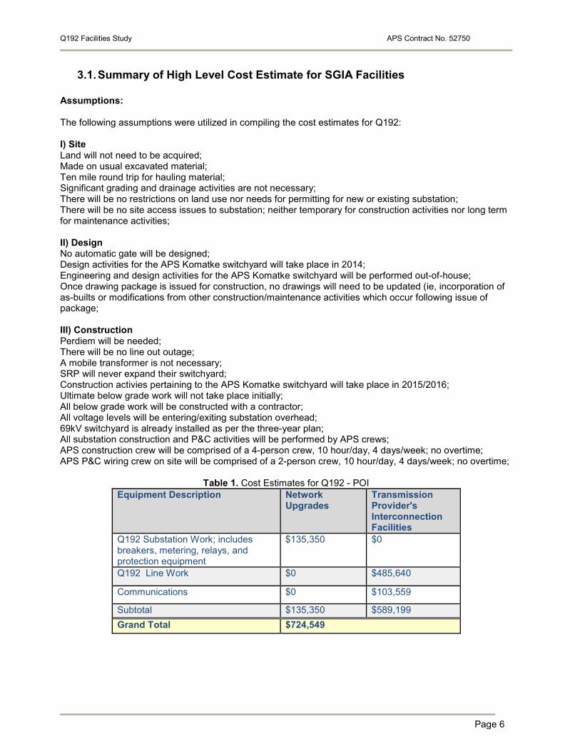
3.1. Summary of High Level Cost Estimate for SGIA Facilities Assumptions: The following assumptions were utilized in compiling the cost estimates for Q192: I) Site Land will not need to be acquired; Made on usual excavated material; Ten mile round trip for hauling material; Significant grading and drainage activities are not necessary; There will be no restrictions on land use nor needs for permitting for new or existing substation; There will be no site access issues to substation; neither temporary for construction activities nor long term for maintenance activities; II) Design No automatic gate will be designed; Design activities for the APS Komatke switchyard will take place in 2014; Engineering and design activities for the APS Komatke switchyard will be performed out-of-house; Once drawing package is issued for construction, no drawings will need to be updated (ie, incorporation of as-builts or modifications from other construction/maintenance activities which occur following issue of package; III) Construction Perdiem will be needed; There will be no line out outage; A mobile transformer is not necessary; SRP will never expand their switchyard; Construction activies pertaining to the APS Komatke switchyard will take place in 2015/2016; Ultimate below grade work will not take place initially; All below grade work will be constructed with a contractor; All voltage levels will be entering/exiting substation overhead; 69kV switchyard is already installed as per the three-year plan; All substation construction and P&C activities will be performed by APS crews; APS construction crew will be comprised of a 4-person crew, 10 hour/day, 4 days/week; no overtime; APS P&C wiring crew on site will be comprised of a 2-person crew, 10 hour/day, 4 days/week; no overtime;
Table 1. Cost Estimates for Q192 - POI Equipment Description Network
Upgrades Transmission Provider's Interconnection Facilities
Q192 Substation Work; includes breakers, metering, relays, and protection equipment
$135,350 $0
Q192 Line Work $0 $485,640
Communications $0 $103,559
Subtotal $135,350 $589,199 Grand Total $724,549
Q192 Facilities Study APS Contract No. 52750
Page 7
PLEASE NOTE: The cost estimates exclude Interconnection Customer costs associated with obtaining permits, easements or income tax or other tax effect and and the cost associated with any Interconnection Customer-owned equipment required for the interconnection of the generators, including protective relaying and a visible open utility disconnect switch. In addition to the construction costs described above, there will be annual operation and maintenance expenses. The estimated cost of annual operation and maintenance expenses is as follows: Common Equipment/ Line Inspections - $3,000 annually
- Two inspections per year - Relay maintenance (estimated at every 4-6 years) - Weed abatement spraying (estimated at 2 times per year)
Breaker Maintenance - $6,000 each time for:
- Overhaul (estimated once every 6 years) Additional actual costs will be charged for:
- Emergency maintenance and repair work such as breaker failure-to-close
3.2. Summary of Construction Time Estimates at the POI The Interconnection Customer’s requested date to energize the interconnection facilities to receive back feed power is March 15, 2017. Table 2 is a preliminary design and construction timeline. Table 2 estimates that it will take approximately 6 months in order to site, certificate, design, permit, procure, and construct the required facilities to interconnect the Q192 project with the exception of lead time for any of the substation materials. The material date noted below is 11/15/2016, but APS may need to order materials prior to the stated date if it is a long lead item or not in stock; putting the earliest possible date for the IC’s project to be energized at 35 months from the date all the appropriate agreements are signed and funded. Given this timeline, the IC’s requested in-servce date of Q2 2013 is not feasible; however, the in-service date of 6/30/17 is feasibile. For the SGIA, a new in-service date will need to be determined. Construction schedule estimates are from the date the Interconnection Customer provides written authorization to proceed, provided all interconnection agreements and funding arrangements are in place.
Q192 Facilities Study APS Contract No. 52750
Page 8
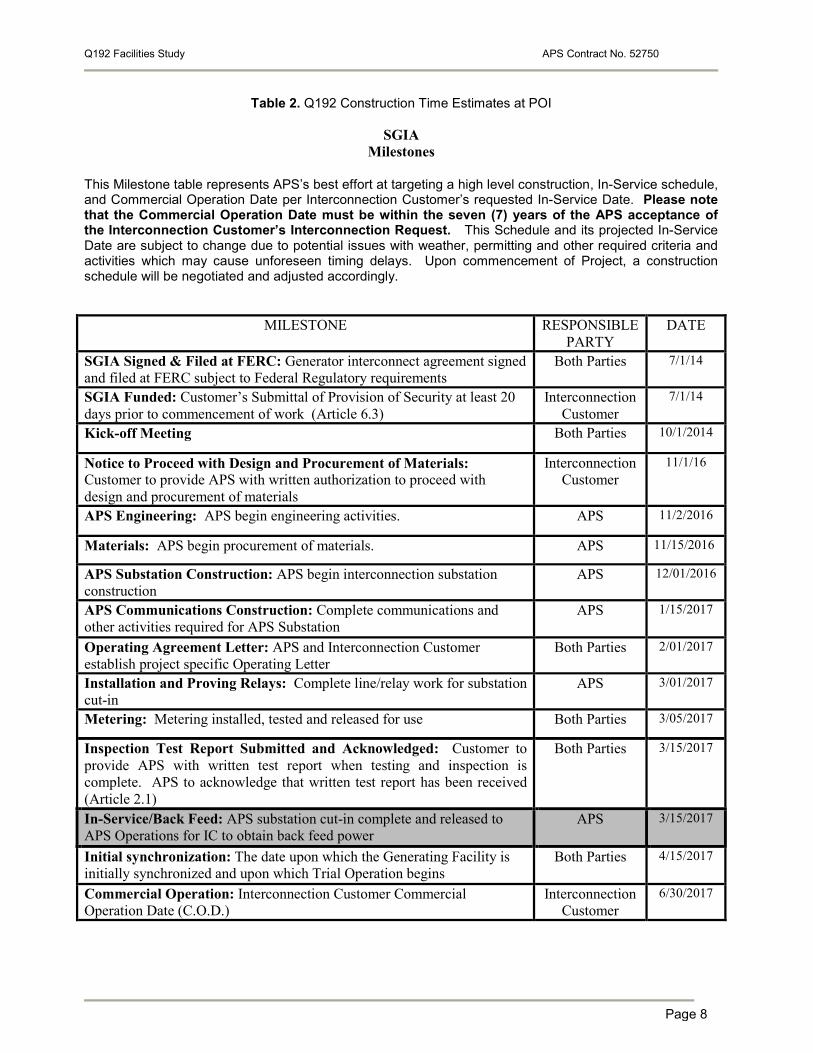
Table 2. Q192 Construction Time Estimates at POI
SGIA Milestones
This Milestone table represents APS’s best effort at targeting a high level construction, In-Service schedule, and Commercial Operation Date per Interconnection Customer’s requested In-Service Date. Please note that the Commercial Operation Date must be within the seven (7) years of the APS acceptance of the Interconnection Customer’s Interconnection Request. This Schedule and its projected In-Service Date are subject to change due to potential issues with weather, permitting and other required criteria and activities which may cause unforeseen timing delays. Upon commencement of Project, a construction schedule will be negotiated and adjusted accordingly.
MILESTONE RESPONSIBLE PARTY
DATE
SGIA Signed & Filed at FERC: Generator interconnect agreement signed and filed at FERC subject to Federal Regulatory requirements
Both Parties 7/1/14
SGIA Funded: Customer’s Submittal of Provision of Security at least 20 days prior to commencement of work (Article 6.3)
Interconnection Customer
7/1/14
Kick-off Meeting Both Parties 10/1/2014
Notice to Proceed with Design and Procurement of Materials: Customer to provide APS with written authorization to proceed with design and procurement of materials
Interconnection Customer
11/1/16
APS Engineering: APS begin engineering activities. APS 11/2/2016
Materials: APS begin procurement of materials. APS 11/15/2016
APS Substation Construction: APS begin interconnection substation construction
APS 12/01/2016
APS Communications Construction: Complete communications and other activities required for APS Substation
APS 1/15/2017
Operating Agreement Letter: APS and Interconnection Customer establish project specific Operating Letter
Both Parties 2/01/2017
Installation and Proving Relays: Complete line/relay work for substation cut-in
APS 3/01/2017
Metering: Metering installed, tested and released for use Both Parties 3/05/2017
Inspection Test Report Submitted and Acknowledged: Customer to provide APS with written test report when testing and inspection is complete. APS to acknowledge that written test report has been received (Article 2.1)
Both Parties 3/15/2017
In-Service/Back Feed: APS substation cut-in complete and released to APS Operations for IC to obtain back feed power
APS 3/15/2017
Initial synchronization: The date upon which the Generating Facility is initially synchronized and upon which Trial Operation begins
Both Parties 4/15/2017
Commercial Operation: Interconnection Customer Commercial Operation Date (C.O.D.)
Interconnection Customer
6/30/2017

Q192 Facilities Study APS Contract No. 52750
Page 9
4. REQUEST FOR TRANSMISSION SERVICE Transmission service was not studied in the Facilities Study. Such a request is required to be made through the APS OASIS site to the APS Transmission Services Trading Group and is outside the scope of the generator Interconnection Request study process.
5. POWER FACTOR REQUIREMENTS The APS Open Access Transmission Tariff (OATT) policy regarding power factor requires all Interconnection Customers, with the exception of wind generators, to maintain an acceptable power factor (typically near unity) at the Point of Interconnection (POI), subject to system conditions. The APS OATT also requires Interconnection Customers to be able to achieve +/- 0.95 power factor at the POI, with the maximum "full-output" VAR capability available at all outputs. Furthermore, APS requires Interconnection Customers to have dynamic voltage control (operational time of less than 5 seconds) and maintain the voltage as specified by the transmission operator within the limitation of +/- 0.95 power factor, as long as the Project is online and generating. If the Project’s equipment is not capable of this type of response, a dynamic reactive device will be required. APS has the right to disconnect the Project from the power grid if system conditions dictate the need to do so in order to maintain system reliability. The method for determining whether or not the generator meets these requirements is to first record the pre-project POI bus voltage. Next, model the generator with zero reactive capabilities at full output. Any shunt devices are turned off. Two synchronous condensers are added to the case with infinite reactive capability. One is at the terminal bus of the unit regulating the bus voltage to 1.0 pu. The other is one bus away from the POI regulating the POI to the pre-project voltage level. The amount of plant losses can be determined by recording the MVAR flow at the POI and adding that to the sum of the synchronous condenser output. Based on the maximum output of the plant, determine the minimum reactive capabilities required to meet the +/-0.95 power factor range. The sum of the two numbers determines the maximum amount of reactive support the project must provide.
5.1 Reactive Support The reactive requirements identified in the SIS are still applicable for this project. Those results may be revisited once the customer has determined the final impedance characteristics of their facility.