Embed Size (px)
Citation preview

Q 79 : Gated spillways and others controlled release facilities 5.28/102.1-R-130
COMMISSION INTERNATIONALE DES GRANDS BARRAGES
------ VINGTIÈME CONGRÈS DES GRANDS BARRAGES
Beijing 2000 ------
INSTALLATION OF GATES ON THE SPILLWAY OF THE PUEBLO VIEJO DAM1
Roger BREMEN Lombardi Engineering Ltd., Minusio, Switzerland
Raúl Ernesto MARTINEZ
Empresa de Generación de Energía Eléctrica, (EGEE), Guatemala
1. INTRODUCTION
The 300 MW Pueblo Viejo-Quixal hydroelectric scheme is located in central Guatemala near the town of Coban. The plant completed in 1986 is the key element of the national electric grid, generating nearly 40% of the national electricity supply once put into operation.
The 130 m high Pueblo Viejo rockfill dam is situated at the entrance of a narrow gorge impounding a reservoir of 460 x 106 m3 capacity with a maximum surface of 14 km2. The general dam layout and the appurtenant structures are shown in Figure 1. After the dam completion, one of the diversion tunnels was plugged, whereas the second was transformed in a bottom outlet (Nr. I) with a capacity of 170 m3/s. A second bottom outlet (Nr. II), on the right bank with a capacity of 460 m3/s was included in the final plant layout to provide an impounding control during the first reservoir filling.
The spillway structure excavated on the left bank consisted of three ungated overflow bays and a spillway chute ending with a flip bucket diverting the flow into the tailrace plunge pool. A 14 m hydraulic head, corresponding to a reservoir at el. 814.00 m a.s.l., was necessary to reach the 3900 m3/s maximum spillway capacity.
1 Installation de vannes sur l’évacuateur de crue de la digue de Pueblo Viejo.

Q 79 : Gated spillways and others controlled release facilities
2
Fig. 1
General layout of the Pueblo Viejo dam.
Vue générale du barrage de Pueblo Viejo
The 26 km long headrace tunnel with a design capacity of 75 m3/s supplies the five Pelton units of the Quixal powerhouse. Figure 2 shows a general downstream view of the dam and of the spillway chute with the tailrace plunge pool in the foreground.

Q 79 : Gated spillways and others controlled release facilities
3
Fig. 2
Downstream view of the dam and the spillway chute.
Vue aval du barrage avec l’évacuateur de crue.
2. PROJECT REVIEW
The feasibility study of the Pueblo Viejo Quixal scheme was completed in 1974 with the construction of the access road started two years later. The strong earthquake affecting Guatemala in 1976 and a severe flood occurring in 1979 during the river diversion caused major design changes of the scheme which had to be incorporated during the construction phase.
One of these changes concerned the design flood hydrograph, whose return period was increased from 1'000 to 10'000 years, resulting in a peak design inflow of 7'500 m3/s and an estimated flood volume of 450 x 106 m3. Due to the advanced construction stage, it was decided to maintain the overall spillway design, but to postpone the installation of the radial gates on the overflow sill until the construction of the Serchil scheme located upstream. Following the completion of this scheme, the additionally available retention capacity of the Serchil reservoir was assumed to sufficiently reduce the peak inflow rate in the Chixoy reservoir thus allowing the installation of the spillway gates.
With a 3.0 m heightening of the Pueblo Viejo dam crest (815 m a.s.l.) and the provisional limit of the Normal Water Level (N.W.L.) to el. 800.00 m a.s.l.

Q 79 : Gated spillways and others controlled release facilities
4
obtained with the postponing of the gate installation, the available flood surcharge was provisionally considered sufficient to pass the revised design flood. However, the completion of the spillway civil works without the installation of the radial gates on the overflow crest resulted in a loss of storage capacity of 15%.
Figure 3 shows the general layout of the ungated spillway bays when put into operation in 1986.
Fig. 3
Layout of the spillway bays prior to the modification works.
Configuration des passes de l’évacuateur de crue avant les travaux de modification.
Due to technical and administrative reasons, the construction of the Serchil scheme was abandoned by the National Electric Company, Instituto Nacional de Electrificación (INDE), presently Empresa de Generación Electrica (EGEE) of Guatemala. To recover the loss of active storage capacity, various solutions were examined in recent years to raise the impounding level to the original design elevation without affecting dam safety.
3. HEIGHTENING OF THE IMPOUNDING LEVEL
The "Instituto Nacional de Electrificación" commissioned Lombardi Engineering Ltd. with the design and construction supervision of the works related to the

Q 79 : Gated spillways and others controlled release facilities
5
heightening of the impounding level of the Chixoy reservoir. The first project step consisted in identifying the most appropriate design solution taking into account safety, operational and cost aspects. In particular, due to the dam type and the central role of the scheme for the national power supply, no temporary or permanent deterioration of its operational and safety conditions were considered acceptable.
A hydrological study including, in particular, the flood records analysis during the dam operation, revealed the suitability of the flood hydrographs considered for the dam design, in order that the same hydrograph could be assumed for the present study. With a maximum inflow rate for the design flood of 7500 m3/s and the initial water level in the reservoir at el. 800.00 m a.s.l corresponding to the sill crest of the ungated spillway, the flood routing analyses indicated a maximum outflow of 3960 m3/s with the reservoir reaching el. 814.18 m a.s.l., thus confirming the ability of the ungated spillway to discharge the 10'000 years flood.
The significant reduction of the peak outflow in comparison with the maximum inflow is achieved by the 200 x 106 m3 available flood storage capacity allowing the temporary impoundment of nearly 45% of the flood volume.
An unchanged Maximum Water Level (M.W.L.) in case of an extreme flood with a higher N.W.L. may only be obtained with an increased capacity of the outflow structures or by a preventive drawdown of the reservoir prior to the flood event.
Concerning the latter solution, it was felt that a meteorological forecasting system in conjunction with a real-time flood prediction was not sufficiently reliable to ensure the safety of the dam during exceptional events. Therefore, only a capacity increase of the outlet structures was considered apt to maintain or increase the flood safety in conjunction with the reservoir heightening.
Preliminary flood routing calculations indicated that for a 3.0 m heightening of the N.W.L. up to el. 803.00 m a.s.l., the required increase of the spillway capacity to maintain an identical M.W.L. corresponds to 400 m3/s, whereas a 4.0 m heightening results in a necessary capacity increase of 600 m3/s. According to the previous evaluations, the following basic solutions, including their combinations, were examined: − operation of both bottom outlets during any flood event, − construction of an auxiliary spillway, and − modification of the existing spillway to increase the discharge capacity.
Without a reliable prediction of the peak inflow, to be effective, the opening of both bottom outlets has to be carried out at the beginning of any flood and not only in the case of extreme events. The frequent and prolonged operation of the outlets with possible structural damages of the outlet tunnels needing periodic repairs and the risks of inappropriate gate opening resulted in the abandon of this solution.

Q 79 : Gated spillways and others controlled release facilities
6
Regarding the construction of an auxiliary spillway, the limited space available on both dam abutments would require the excavation of an additional tunnel. With a minimum internal diameter evaluated of 6.0 m and relatively significant intake and outlet structures, the construction costs of an auxiliary spillway would have been relatively high although the solution would be technically feasible.
Finally, regarding the modification of the existing spillway, basically two options or their combination were considered, namely: − lowering of the weir crest elevation to increase the specific discharge, and − increasing the length of the weir crest (labyrinth or similar).
For a N.W.L. at el. 803.00 m a.s.l., a developed overflow sill length of nearly 60 m would be needed to discharge the design flood, which corresponds almost to the double of the present crest length. Solutions including a combination of a gated spillway and a labyrinth weir were also studied. These alternatives implied, however, relatively significant concrete demolition works of both the overflow crest and the already built spillway piers, which could hardly be carried out during one single summer season.
The lowering of the spillway crest combined with the installation of radial gates was finally found to be the most adequate solution to increase the spillway capacity, although some negative aspects of this alternative had to be compensated for, as will be discussed further on.
Flood routing analyses revealed that for a N.W.L. at el. 803.00 m a.s.l., a 1.10 m lowering of the existing overflow crest down to el. 798.90 m a.s.l. was necessary to maintain a minimum freeboard of 1.0 m (M.W.L. at el. 814.00 m a.s.l.) in the case of design flood. Model tests carried out at the Laboratory of Hydraulic Constructions of the Swiss Federal Institute of Technology in Lausanne confirmed an overall satisfactory behaviour of the modified spillway for a peak outflow discharge of 4370 m3/s. The finally adopted design for the spillway modification works is shown in Figure 4, in which the existing and the modified spillway sections are compared.
In comparison with other alternatives, the proposed design to increase the spillway capacity presented the following advantages: − minimum modification of the flow conditions in the spillway approaching
channel, overflow crest, spillway chute and tailrace plunge pool, − limited civil works to be carried out over one single summer, maintaining as
much of the actual layout of the spillway structure as possible, and − no need for any preventive measures in case of floods. The gate operation is
controlled only by the reservoir level.
The primary weak aspect of the suggested solution concerns the operational safety of the gated spillway. The reliability and maintenance of the gates and of the hoisting mechanism are essential factors of dam safety, considering in

Q 79 : Gated spillways and others controlled release facilities
7
particular the severe local conditions regarding power shutdowns, accessibility and climate.
Fig. 4
Spillway modification works: a) existing spillway, and b) modified spillway without installed gates.
Travaux de modification de l’évacuateur de crues: a) evacuateur avant travaux, et b) évacuateur modifié avec l’installation de vannes.

Q 79 : Gated spillways and others controlled release facilities
8
To reduce the risks of inadequate gate operation and/or malfunctioning, various specific technical solutions and operation rules were adopted for the hydro-mechanical equipment as described hereafter.
4. SAFETY REQUIREMENTS OF THE GATED SPILLWAY
The safety of a dam equipped with gates is highly affected by the reliability of the hydro-mechanical and electrical equipment during floods. Their satisfactory operation depends on the selected gate mechanism and operating system as well as on the correct application of operating and maintenance rules by the local staff. Measures to reduce the operational risks of gates must therefore cover both the gate design and the equipment maintenance. After a detailed analysis of the various factors affecting the operational reliability of the gates and the safety of the dam, the following basic measures were adopted within the project: − A concrete counterweight fixed on a prolongation of the gate arms provides an
opening tendency of the radial gates. Pressure losses in the hydraulic circuit exceeding a given value will automatically result in the gates opening. No valves or mechanical devices were installed which could cause a blockage of the gates in the closed position.
− Each gate is equipped with a completely independent hydraulic circuit. Gate opening requires no power supply and may be activated by pressing one single button. To remain closed, the hydraulic circuit of the gate must be active.
− In case of a gate malfunction or blockage in the closed position, a rising water level above the upper gate edge (803.40 m a.s.l.) will result in a subsequent gate failure with the corresponding hydraulic section becoming free for flow release.
In addition to the previous measures, a diesel generator for the emergency power supply and the habitually adopted alarm systems were installed.
Regarding the maintenance of the equipment, it must be mentioned that the system is designed in order that any major malfunctioning results in the gates opening with the subsequent water loss the maintenance staff to carry out any required repair work as quickly as possible. Furthermore, the services provided by the consultant include a 5 years monitoring of the dam and of the equipment as well as its maintenance.
5. CIVIL WORKS
The civil works carried out on the site may be summarised as follows: − lowering of the overflow weir by demolition and concreting works to achieve
the 12% capacity increase required by the project,

Q 79 : Gated spillways and others controlled release facilities
9
− optimisation of the hydraulic behaviour of the spillway, in particular for the design flood by a prolongation of the central piers (see Fig.4b),
− stabilisation works on the access road between the dam and the power intake building to ensure the accessibility of the dam under any condition, and
− minor adaptations of the existing civil structures required for the equipment installation and construction of an additional control building.
The need to keep the spillway operational during the rainy season and to avoid, if possible, any water loss had to be taken into account during the design and planning of the civil works. The contractor's installations and the works on the access road, as well as the construction of the additional control building, were therefore carried out at the beginning of the summer immediately after the start of the reservoir lowering of the reservoir.
Only by mid-January 1998 the reservoir descended below el. 798.00 m a.s.l., allowing the beginning of the works on the spillway structure. For the removal of the 1200 m3 concrete to be demolished, different methodologies were used depending on the concrete properties. The highly reinforced superficial concrete of the overflow weir was removed up to an average thickness of 20 cm using robotised hydro-demolition equipment with a pressure of 2000 bars. The same equipment was used for superficial concrete removal on the spillway piers as shown in Figure 5. Following the cutting of the superficial reinforcement bars, a 50 cm x 50 cm mesh of vertical drills down to the lower demolition limit (see Fig. 4) was executed on each spillway bay. The demolition and removal of the mass concrete was then carried out using various hydro-splitting jacks combined with pneumatic hammers. The demolition down to a maximum concrete thickness of 2.1 m was time consuming and somewhat difficult due to the locally dense reinforcement and the excellent mechanical properties of the concrete.
For the reconstruction of the modified weir, each spillway bay was subdivided into three elements in the upstream-downstream direction. After the placement of the reinforcement bars and of the formworks, the upstream and downstream elements were poured in parallel, whereas the central element was concreted only after the complete shrinkage of the lateral blocks.
Extensive laboratory tests were performed both on the aggregates and on the concrete mix in order to identify the most suitable mix. To limit the pouring temperatures, ice was added to the concrete. Finally, to avoid superficial cracking, the concrete surface was protected using jute bags for approximately one month after concreting.

Q 79 : Gated spillways and others controlled release facilities
10
Fig. 5
General view of the demolition works on the spillway.
Vue générale des travaux de démolition de l’évacuateur.
6. DESIGN AND INSTALLATION OF THE RADIAL GATES
The main functional characteristics of the 40 tons radial gates and of the hoisting equipment may be summarised as follows : − Each gate is connected to one hydraulic servomotor and operated
automatically or manually from the control building. − The automatic opening tendency of each gate is assured by the concrete
counterweight and no external devices interfere with this process while the closing operation is being performed by the hydraulic servomotor, which is in traction to keep the gate closed.
− Each gate is equipped with an individual oil pumping unit of compact construction with a completely independent hydraulic circuit. For the normal operation, each pumping set is connected to one gate, but in case of maintenance, it can be connected to any gate to ensure the operation of the plant. Each pumping unit is oversized to operate all the gates from one unit if needed.
− A reserve electro-pump was installed on each pumping unit, as well as a manual pump.

Q 79 : Gated spillways and others controlled release facilities
11
− In the case of a power shutdown of the grid exceeding 1 min., the diesel generator starts automatically supplying the hydraulic units and the control cubicles.
The structural parts of the gates were manufactured in various sub-assemblies in Switzerland and Europe (skin plate, tubular beam, main arms, axles, tubular stiffeners, counterweight and counterweight arms), painted with a primer coat and pre-assembled in the workshop for quality and dimensional control by EGEE. Following 6 weeks shipping, the structural parts arrived on the job site in containers in the same sub-assemblies as manufactured to facilitate local transportation.
Since only 7 months were available to complete the civil and erection works on the spillway, a precise working programme was established and periodically updated in co-ordination with the civil subcontractor. Due to the very tight working schedule, the gate assembly on each bay had to be carried out in parallel with the two working shifts of the civil subcontractor.
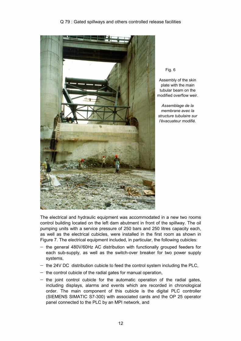
The gate sub-assemblies were lowered from the existing bridge by means of mobile cranes and the final assembly (welding and bolting) was performed directly on the spillway floor as shown in Figure 6. After the final assembly of the structural parts of the gates, the sand-blasting of site-welded joints and final coats of paint were carried out using the mobile cranes. Strong winds and heavy rainfall at the beginning of the winter season caused additional difficulties during painting and erection works.
The installation of the electrical cubicles and wiring, as well as the hydraulic units including the hydraulic piping system, were performed in parallel with the mechanical assembling works. Just after the preliminary functional tests of the hydraulic units, the servomotors were attached to the gate arms and upper supports.
For safety reasons, the concrete filling of the counterweight envelopes was done only at the end of the assembling works and, in particular, after the servomotor installation and operation tests to avoid any sudden gate opening without control.
Q 79 : Gated spillways and others controlled release facilities
12
The electrical and hydraulic equipment was accommodated in a new two rooms control building located on the left dam abutment in front of the spillway. The oil pumping units with a service pressure of 250 bars and 250 litres capacity each, as well as the electrical cubicles, were installed in the first room as shown in Figure 7. The electrical equipment included, in particular, the following cubicles: − the general 480V/60Hz AC distribution with functionally grouped feeders for
each sub-supply, as well as the switch-over breaker for two power supply systems,
− the 24V DC distribution cubicle to feed the control system including the PLC, − the control cubicle of the radial gates for manual operation, − the joint control cubicle for the automatic operation of the radial gates,
including displays, alarms and events which are recorded in chronological order. The main component of this cubicle is the digital PLC controller (SIEMENS SIMATIC S7-300) with associated cards and the OP 25 operator panel connected to the PLC by an MPI network, and
Fig. 6
Assembly of the skin plate with the main
tubular beam on the modified overflow weir.
Assemblage de la membrane avec la
structure tubulaire sur l’évacuateur modifié.

Q 79 : Gated spillways and others controlled release facilities
13
− the control cubicle for the bottom outlet gate to enable its remote control, including the wiring connection to the existing local control cubicle.
The diesel generator set with its cubicle and the diary fuel tank were installed in the second room of the new control building.
In the automatic mode, the gate operation is controlled by the reservoir water level according to the sequence shown in the following table.
Fig. 7
Control room with oil pumping sets and electrical cubicles.
Local de commande avec groupe
hydrauliques et armoires de commande.

Q 79 : Gated spillways and others controlled release facilities
14
TABLE 1Sequence of events for gate operation
Reservoir elevation [m a.s.l.] Gate operation sequence in automatic mode
Water level Water level Left gate Central gate Right gate
increasing decreasing opening [m] opening [m] opening [m]
803.00 below 803.00 closed closed closed
803.05 803.00 closed 2.0 closed
803.10 803.05 1.0 complete 1.0
803.15 803.10 2.0 complete 2.0
803.20 803.15 complete complete complete
For the provisional commissioning, only dry functional tests of the equipment were performed due to the low water level in the reservoir. A general view of the equipment at the provisional commissioning is shown in Figure 8.
Fig. 8
General downstream view of the modified spillway with the installed radial gates.
Vue générale de l’évacuateur de crue modifié avec l’installation des vannes secteur.
The reservoir reached the operating water level at el. 803.00 m a.s.l only 6 weeks after commissioning and maximum load tests were performed. The functional capacity of the gates was successfully tested under severe flood conditions

Q 79 : Gated spillways and others controlled release facilities
15
caused by the passage of the hurricane Mitch. The hurricane, which affected the Chixoy watershed only marginally caused one of the most severe floods to be passed by the spillway since the beginning of the plant operation.
7. GENERAL WORK SCHEDULES AND COSTS
After the award of the supply and construction contract in Autumn 1997 by the Instituto Nacional de Electrificación of Guatemala to Noell Stahl- und Maschinenbau GmbH (NOELL), Hydropower Engineering Division, Switzerland, the civil works started on site in January 1998 at the beginning of the dry season. The civil works were carried out by the local subcontractor Swissboring with the exception of the hydro-demolition works, for which a U.S. firm was selected.
The radial gates and the control system were manufactured by several subcontracting companies in Switzerland and in Europe, under the supervision and quality control management of NOELL.
The engineering services including all design phases and construction supervision were provided by Lombardi Engineering Ltd. of Switzerland supported by Colenco Power Consulting for the preparation of the equipment specifications.
With a reservoir surface of approx. 14 km2, the 3.0 m heightening of the N.W.L. offers additional active storage of 42 x 106 m3. According to the hydrological data available, the additional average power generation with the gates installed can be estimated at nearly 40 GWh per year.
The costs of the spillway modification works, financed under a Swiss mixed credit agreement, including civil works, hydromechanical equipment and consultant services are approx. US$ 3.5 mio. Assuming a 30 year life time of the gates and including yearly operation and maintenance costs (2% of the equipment costs) leads to a unit cost for the additional power of only US$ 0.01/kWh.
Considering a reference cost for electric power of US$ 0.05/kWh, results in a yearly benefit of approx. 2.0 mio US$, which is of the order of magnitude as the costs of the spillway modification works. Figure 9 shows the operation of the flip bucket shortly after the completion of the gate installation.

Q 79 : Gated spillways and others controlled release facilities
16
Fig. 9
Operation of the spillway's flip bucket during the Mitch hurricane, 2 months after the gate installation.
Opération de saut de ski denté pendant le hurricaine Mitch 2 mois après l’installation des vannes.
ABSTRACT
The 300 MW Pueblo Viejo-Quixal hydroelectric scheme located in central Guatemala and completed in 1986, includes a 130 m high rockfill dam with an ungated spillway of 3900 m3/s maximum capacity.
A severe flood occurred in 1979 during the dam construction leading to a re-evaluation of the design flood hydrograph from 1’000-years to a 10’000-years event. As part of the design modifications, it was suggested, for safety reasons, to complete all civil works according to the original design, but to postpone the installation of the radial gates on the spillway.
The report presents the analyses and the characteristics of the finally adopted solution including a description of the construction details insuring an appropriate gate operation under any condition. The project mainly consists in an increase of the spillway capacity by lowering the weir crest elevation of the fixed weir combined with the installation of three 4.5 m high and 12.00 m wide radial gates equipped with concrete counterweights. The design of the spillway modification

Q 79 : Gated spillways and others controlled release facilities
17
works and the selection of the hydromechanical equipment characteristics were dictated by unusually severe safety requirements.
Shortly after completion, the hurricane “Mitch” affected in November 1998 the watershed of the Chixoy river, resulting in relevant floods safety discharges by the new spillway structure.
RESUME
L’aménagement hydroélectrique de Pueblo Viejo Quixal avec une puissance installée de 300 MW, se situe dans la partie centrale du Guatemala. Mis en service en 1986, l’aménagement comporte une digue en enrochement de 130 m avec un évacuateur de crues non vanné d’une capacité maximale de 3900 m3/s.
Une crue importante survenue en 1979 pendant la construction du barrage a amenée à considérer une crue de projet avec une période de retour de 10'000 ans au lieu de celle de 1'000 , retenue dans le cadre du projet initial. Cette modification avait conduit à compléter les ouvrage de génie civil, mais à retarder l’installation des vannes sur l’évacuateur.
Le rapport présente l’analyse et les caractéristiques de la solution adoptée ainsi qu’une description détaillée de la construction assurant les opérations de ouverture e de fermeture des vannes en toutes conditions. Le projet consiste principalement à augmenter la capacité de l’évacuateur de crue par un abaissement du seuil d’évacuation de l’évacuateur fixe et l’installation de 3 vannes de 4.5 m de hauteur et de 12 m de longueur équipés de contrepoids en béton. L’étude de la modification de l’évacuateur de crue et les caractéristiques de l’équipement hydroélectrique se basent sur des prescriptions de sécurité particulièrement sévères.
Peut de temps après le fin des travaux, l’ouragan “Mitch” modifia en novembre 1998 le volume du fleuve Chixoy dont la crue fut drainée par la nouvelle structure de l’évacuateur.