Embed Size (px)
Citation preview
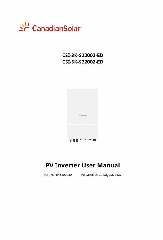
CSI-3K-S22002-ED CSI-5K-S22002-ED
PV Inverter User Manual (Part No: 6431000501 Released Date: August, 2020)
Contents 1 Introduction ................................................................................. 1
1.1 General Information ......................................................... 1 1.2 User Manual Disclaimer .................................................... 1 1.3 Limitation of Liability ......................................................... 1 1.4 Target Group...................................................................... 1 1.5 Symbol Conventions ......................................................... 1
1.5.1 Warnings in the manual ......................................... 2 1.5.2 Labels on product and packaging ......................... 2
2 Safety Instruction......................................................................... 3 2.1 General Safety ................................................................... 3 2.2 Notice for Use .................................................................... 3
2.2.1 Personnel requirements ......................................... 3 2.2.2 Operation requirements ........................................ 3 2.2.3 Protecting labels ..................................................... 3
3 Product Overview ........................................................................ 4 3.1 Product Introduction......................................................... 4 3.2 Appearance ........................................................................ 4 3.3 Product Nameplate ........................................................... 5
4 Storage ......................................................................................... 7 5 Unpackaging and Inspection ...................................................... 7 6 Installation.................................................................................... 8
6.1 Basic Installation Requirements ...................................... 8 6.2 Mounting Wall-mounting Bracket ................................. 10 6.3 Installing Inverter ............................................................ 11
7 Electrical Connection ................................................................. 12 7.1 Safety ................................................................................ 12 7.2 Network Diagram ............................................................ 12 7.3 Meter/CT Connection (Optional) .................................... 12
7.3.1 Meter connection .................................................. 12 7.3.2 CT connection ........................................................ 13
7.4 Cable Description ............................................................ 13 7.5 Wiring PE Cable ............................................................... 13 7.6 Wiring AC Output ............................................................ 14
7.7 Wiring DC Input ............................................................... 16 7.71 Requirement for DC input ..................................... 17 7.72 Wiring ...................................................................... 17 7.73 Connecting PV array (DC input) ............................ 18
7.8 Wiring CT/Meter .............................................................. 19 8 Communication ......................................................................... 20
8.1 Communication Mode .................................................... 20 8.2 RS485 ................................................................................ 20 8.3 External GPRS (Optional) ................................................ 20 8.4 External WiFi .................................................................... 20
9 Commissioning Inverter ........................................................... 21 9.1 Checking Electrical .......................................................... 21 9.2 Checking Mechanical ...................................................... 21 9.3 Start-UP Inverter ............................................................. 21 9.4 LED Indicators.................................................................. 22 9.5 Switch off.......................................................................... 22
10 Daily Maintenance ................................................................... 23 11 SPD Maintenance ..................................................................... 24 12 Trouble Shooting ..................................................................... 25
12.1 Warning .......................................................................... 25 12.2 Errors .............................................................................. 25
13 Handling the Inverter .............................................................. 27 13.1 Removing Inverter ........................................................ 27 13.2 Packing Inverter ............................................................ 27 13.3 Disposing Inverter......................................................... 27
ANNEX A: Acronyms and Abbreviations...................................... 28 ANNEX B: Specification ................................................................. 29
1 Introduction
1 / 30
1 Introduction
1.1 General Information This manual provides important safety information on relating to the installation,
maintenance and usage of single phase PV inverters. Both users and professional
installers must read these guidelines carefully and strictly follow these instructions.
Failure to follow these instructions may result in death, serious injury or
property damage.
Only qualified professionals and service personnel can do the installation and operation
(refer to 62109-1). Installers must inform end-users (consumers) about the aforesaid
information accordingly.
This manual is only valid for the PV inverter types, CSI-3K-S22002-ED and
CSI-5K-S22002-ED produced by Canadian Solar Inc.
1.2 User Manual Disclaimer The information contained in this manual is subject to change by Canadian Solar Inc.
without prior notice. Canadian Solar Inc. gives no warranty of any kind whatsoever,
either explicitly or implicitly, with respect to the information contained herein.
In the event of any inconsistency among different language versions of this document,
the English version shall prevail. Please refer to our product lists and documents
published on our website at: http://www.canadiansolar.com as these lists are updated on
a regular basis.
1.3 Limitation of Liability Canadian Solar Inc. shall not be held responsible for damages of any kind,
including-without limitation-bodily harm, injury or damage to property, in connection
with handling PV inverters, system installation, or compliance or non-compliance with
the instructions set forth in this manual.
1.4 Target Group This document is intended for installers and users.
1.5 Symbol Conventions The symbols that may be found in this document or on the product packaging are
defined as follows.
1 Introduction
2 / 30
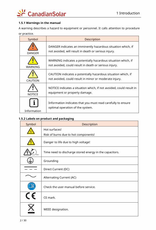
1.5.1 Warnings in the manual
A warning describes a hazard to equipment or personnel. It calls attention to procedure
or practice.
Symbol Description
DANGER
DANGER indicates an imminently hazardous situation which, if not avoided, will result in death or serious injury.
WARNING
WARNING indicates a potentially hazardous situation which, if not avoided, could result in death or serious injury.
CAUTION
CAUTION indicates a potentially hazardous situation which, if not avoided, could result in minor or moderate injury.
NOTICE
NOTICE indicates a situation which, if not avoided, could result in equipment or property damage.
Information
Information indicates that you must read carefully to ensure optimal operation of the system.
1.5.2 Labels on product and packaging
Symbol Description
Hot surfaces!
Risk of burns due to hot components!
Danger to life due to high voltage!
Time need to discharge stored energy in the capacitors.
Grounding
Direct Current (DC)
Alternating Current (AC)
Check the user manual before service.
CE mark.
WEEE designation.
2 Safety Instruction
3 / 30
2 Safety Instruction
2.1 General Safety The Inverter has been designed and tested strictly according to the international safety
codes, however, certain safety precautions must be observed when installing and
operating this inverter. Read and follow all the instructions, cautions and warnings in this
user manual carefully before any work and keep this manual for future reference.
2.2 Notice for Use
2.2.1 Personnel requirements
Only qualified personnel are allowed to install and commission the inverter, they should:
1) Receive professional training and get the authorization.
2) Be familiar with the safety specification about the electrical system.
3) Be familiar with the local requirements, rules and regulations.
4) Understand the composition and working principles of the grid-tied PV system.
2.2.2 Operation requirements
Use the inverter in installations that meet the following specifications only.
1) Permanent installation is required.
2) The electrical installation must meet all the applications and standards.
3) The inverter must be installed according to the instructions stated in this manual.
4) The inverter must be installed according to the correct technical specifications.
5) To startup the inverter, the Grid Main Switch (AC) must be switched on, before the
solar panel’s DC solar switched on. To stop the inverter, the Grid Supply Main Switch (AC)
must be switched off before the solar panel’s DC isolator switched off.
2.2.3 Protecting labels
1) Do not scrawl or damage any labels on the inverter enclosure because these labels
contain important information about safe operation.
2) Do not scrawl or damage the nameplate on the inverter enclosure. This nameplate
contains important product information.
3 Product Overview
4 / 30
3 Product Overview
3.1 Product Introduction The inverters are single-phase gird-connected PV string inverters without transformer,
which can convert the DC power from the photovoltaic (PV) strings into alternating
current (AC) power, and feed the power into the power grid.
This document involves the following product models:
CSI-3K-S22002-ED; CSI-5K-S22002-ED.
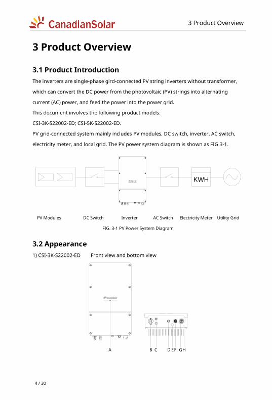
PV grid-connected system mainly includes PV modules, DC switch, inverter, AC switch,
electricity meter, and local grid. The PV power system diagram is shown as FIG.3-1.
KWH
PV Modules DC Switch Inverter AC Switch Electricity Meter Utility Grid
FIG. 3-1 PV Power System Diagram
3.2 Appearance 1) CSI-3K-S22002-ED Front view and bottom view
A B C D EF GH
3 Product Overview
5 / 30
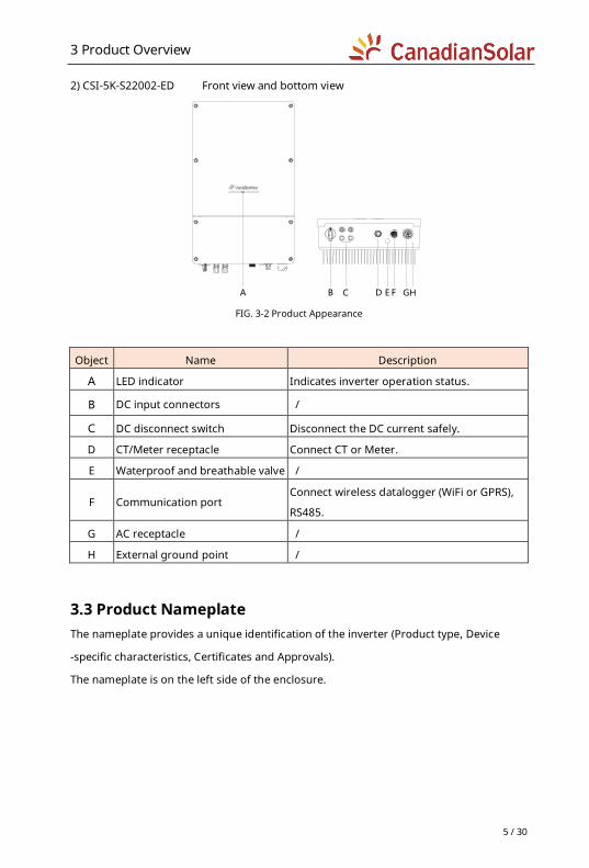
2) CSI-5K-S22002-ED Front view and bottom view
A B C D E F GH
FIG. 3-2 Product Appearance
Object Name Description
A LED indicator Indicates inverter operation status.
B DC input connectors /
C DC disconnect switch Disconnect the DC current safely.
D CT/Meter receptacle Connect CT or Meter.
E Waterproof and breathable valve /
F Communication port Connect wireless datalogger (WiFi or GPRS),
RS485.
G AC receptacle /
H External ground point /
3.3 Product Nameplate The nameplate provides a unique identification of the inverter (Product type, Device
-specific characteristics, Certificates and Approvals).
The nameplate is on the left side of the enclosure.

3 Product Overview
6 / 30
FIG.3-3 Inverter Nameplate (for reference)
4 Storage
7 / 30
4 Storage The following requirements should be met when the inverters need to be stored:
Do not unpack the inverter.
Storage temperature: –40°C ~ +70°C.
Storage humidity: 0% ~ 100%RH (Non-Condensing).
The stored warehouse should be clean, well-ventilated, and non-corrosive gas,
meanwhile it should be in a state of unimpeded access.
No smoking, no illegal use of electricity and fire.
When storing inverters, do not stack more than the allowed layers to avoid damage,
which number marked on the product packaging.
Regular inspection is required during the storage.
After long periods storage, the inverters need to be inspected and tested by qualified
persons before they are put into use.
5 Unpackaging and Inspection Before unpacking the inverter, check the package appearance thoroughly, such as any
holes and cracks, and check the inverter model accordingly. If discover any damage to
the packaging which indicates the inverter may have been damaged, or the inverter
model is not what you requested, do not unpack the product and contact your dealer
immediately.
After opening the package, check all of the accessories carefully in the carton. If any
damage is found or any component is missing, contact your dealer.
Note:
For details information about the components, see the packing list document in the
packing case.
6 Installation
8 / 30
6 Installation
6.1 Basic Installation Requirements 1) Do not install the inverter on the structures constructed of flammable or thermolabile
materials.
2) The installation surface must be strong enough to bear the inverter's weight for a long
period time. (Please check the inverter’s weight in the product specification of ANNEX B).
3) The inverter is protected to IP65, can be installed indoors and outdoors.
4) The humidity of the installation location should be below 100% without condensation.
5) The ambient temperature should be between -25°C to 60°C.
6) Install at eye-level for easy operation.
7) Do not install the inverter near television antenna or any other antennas and antenna
cables.
8) Ensure the inverter is out of children's reach.
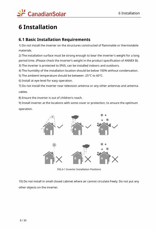
9) Install inverter at the locations with some cover or protection, to ensure the optimum
operation.
FIG.6-1 Inverter Installation Positions
10) Do not install in small closed cabinet where air cannot circulate freely. Do not put any
other objects on the inverter.
6 Installation
9 / 30
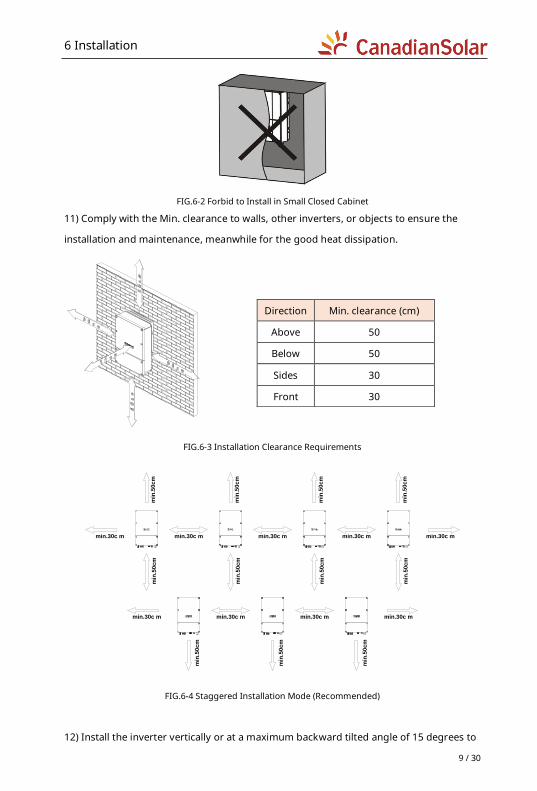
FIG.6-2 Forbid to Install in Small Closed Cabinet
11) Comply with the Min. clearance to walls, other inverters, or objects to ensure the
installation and maintenance, meanwhile for the good heat dissipation.
FIG.6-3 Installation Clearance Requirements
min.30c m
min
.50cm
min
.50cm
min.30c m min.30c m min.30c m min.30c m
min.30c mmin.30c mmin.30c m min.30c m
min
.50cm
min
.50cm
min
.50cm
min
.50cm
min
.50cm
min
.50cm
min
.50cm
min
.50cm
min
.50cm
FIG.6-4 Staggered Installation Mode (Recommended)
12) Install the inverter vertically or at a maximum backward tilted angle of 15 degrees to
Direction Min. clearance (cm)
Above 50
Below 50
Sides 30
Front 30
6 Installation
10 / 30
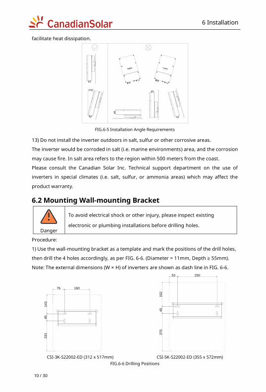
facilitate heat dissipation.
≤15°
FIG.6-5 Installation Angle Requirements
13) Do not install the inverter outdoors in salt, sulfur or other corrosive areas.
The inverter would be corroded in salt (i.e. marine environments) area, and the corrosion
may cause fire. In salt area refers to the region within 500 meters from the coast.
Please consult the Canadian Solar Inc. Technical support department on the use of
inverters in special climates (i.e. salt, sulfur, or ammonia areas) which may affect the
product warranty.
6.2 Mounting Wall-mounting Bracket
Danger
To avoid electrical shock or other injury, please inspect existing
electronic or plumbing installations before drilling holes.
Procedure:
1) Use the wall-mounting bracket as a template and mark the positions of the drill holes,
then drill the 4 holes accordingly, as per FIG. 6-6. (Diameter = 11mm, Depth ≥ 55mm).
Note: The external dimensions (W × H) of inverters are shown as dash line in FIG. 6-6.
33
14
51
43
76 160
37
54
51
52
53 250
CSI-3K-S22002-ED (312 x 517mm) CSI-5K-S22002-ED (355 x 572mm)
FIG.6-6 Drilling Positions
6 Installation
11 / 30
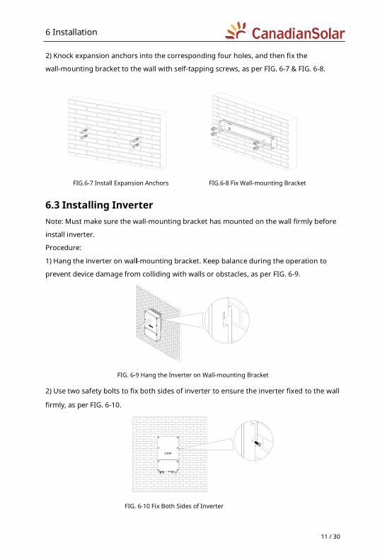
2) Knock expansion anchors into the corresponding four holes, and then fix the
wall-mounting bracket to the wall with self-tapping screws, as per FIG. 6-7 & FIG. 6-8.
FIG.6-7 Install Expansion Anchors FIG.6-8 Fix Wall-mounting Bracket
6.3 Installing Inverter Note: Must make sure the wall-mounting bracket has mounted on the wall firmly before
install inverter.
Procedure:
1) Hang the inverter on wall-mounting bracket. Keep balance during the operation to
prevent device damage from colliding with walls or obstacles, as per FIG. 6-9.
FIG. 6-9 Hang the Inverter on Wall-mounting Bracket
2) Use two safety bolts to fix both sides of inverter to ensure the inverter fixed to the wall
firmly, as per FIG. 6-10.
FIG. 6-10 Fix Both Sides of Inverter
7 Electrical Connection
12 / 30
7 Electrical Connection
7.1 Safety
Danger
Danger to life due to lethal voltages in the inverter!
Before performing any work on the inverter, must disconnect both AC and
DC sides.
Warning
Damage to electronic components may happen due to electrostatic
discharge. Take appropriate ESD precautions when replacing and
installing the inverter.
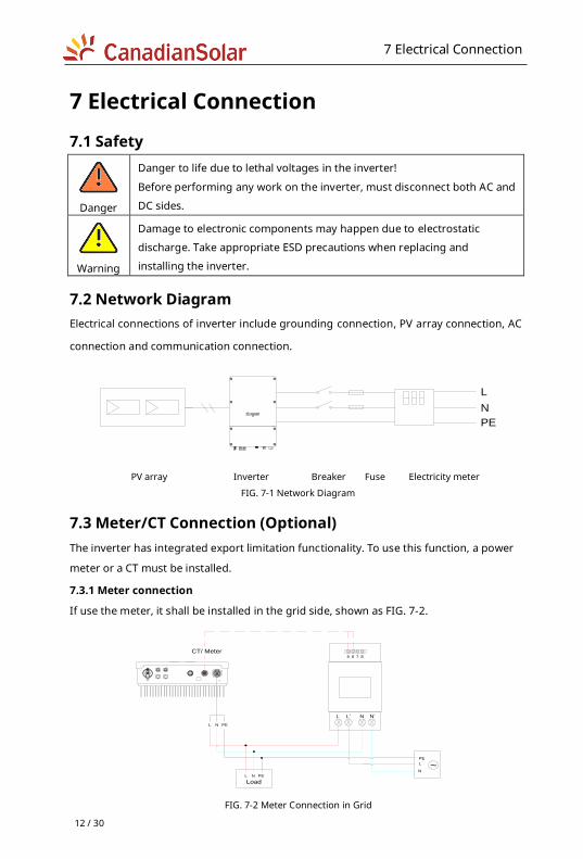
7.2 Network Diagram Electrical connections of inverter include grounding connection, PV array connection, AC
connection and communication connection.
L
N
PE
PV array Inverter Breaker Fuse Electricity meter
FIG. 7-1 Network Diagram
7.3 Meter/CT Connection (Optional) The inverter has integrated export limitation functionality. To use this function, a power
meter or a CT must be installed.
7.3.1 Meter connection
If use the meter, it shall be installed in the grid side, shown as FIG. 7-2.
L L' N N'
5 6 7 8
L N PE
L
N
PE
L N PE
Load
~
CT/ Meter
FIG. 7-2 Meter Connection in Grid
7 Electrical Connection
13 / 30
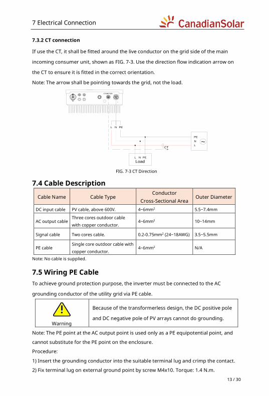
7.3.2 CT connection
If use the CT, it shall be fitted around the live conductor on the grid side of the main
incoming consumer unit, shown as FIG. 7-3. Use the direction flow indication arrow on
the CT to ensure it is fitted in the correct orientation.
Note: The arrow shall be pointing towards the grid, not the load.
L N PE
L
N
PE
~CT
CT/METER
L N PE
Load FIG. 7-3 CT Direction
7.4 Cable Description
Cable Name Cable Type Conductor
Cross-Sectional Area Outer Diameter
DC input cable PV cable, above 600V. 4~6mm2 5.5~7.4mm
AC output cable Three cores outdoor cable
with copper conductor. 4~6mm2 10~14mm
Signal cable Two cores cable. 0.2-0.75mm2 (24~18AWG) 3.5~5.5mm
PE cable Single core outdoor cable with
copper conductor. 4~6mm2 N/A
Note: No cable is supplied.
7.5 Wiring PE Cable To achieve ground protection purpose, the inverter must be connected to the AC
grounding conductor of the utility grid via PE cable.
Warning
Because of the transformerless design, the DC positive pole
and DC negative pole of PV arrays cannot do grounding.
Note: The PE point at the AC output point is used only as a PE equipotential point, and
cannot substitute for the PE point on the enclosure.
Procedure:
1) Insert the grounding conductor into the suitable terminal lug and crimp the contact.
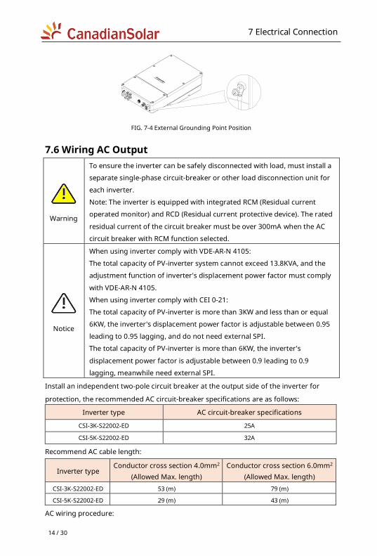
2) Fix terminal lug on external ground point by screw M4x10. Torque: 1.4 N.m.
7 Electrical Connection
14 / 30
FIG. 7-4 External Grounding Point Position
7.6 Wiring AC Output
Warning
To ensure the inverter can be safely disconnected with load, must install a
separate single-phase circuit-breaker or other load disconnection unit for
each inverter.
Note: The inverter is equipped with integrated RCM (Residual current
operated monitor) and RCD (Residual current protective device). The rated
residual current of the circuit breaker must be over 300mA when the AC
circuit breaker with RCM function selected.
Notice
When using inverter comply with VDE-AR-N 4105:
The total capacity of PV-inverter system cannot exceed 13.8KVA, and the
adjustment function of inverter's displacement power factor must comply
with VDE-AR-N 4105.
When using inverter comply with CEI 0-21:
The total capacity of PV-inverter is more than 3KW and less than or equal
6KW, the inverter's displacement power factor is adjustable between 0.95
leading to 0.95 lagging, and do not need external SPI.
The total capacity of PV-inverter is more than 6KW, the inverter's
displacement power factor is adjustable between 0.9 leading to 0.9
lagging, meanwhile need external SPI.
Install an independent two-pole circuit breaker at the output side of the inverter for
protection, the recommended AC circuit-breaker specifications are as follows:
Inverter type AC circuit-breaker specifications
CSI-3K-S22002-ED 25A
CSI-5K-S22002-ED 32A
Recommend AC cable length:
Inverter type Conductor cross section 4.0mm2
(Allowed Max. length) Conductor cross section 6.0mm2
(Allowed Max. length) CSI-3K-S22002-ED 53 (m) 79 (m)
CSI-5K-S22002-ED 29 (m) 43 (m)
AC wiring procedure:
7 Electrical Connection
15 / 30
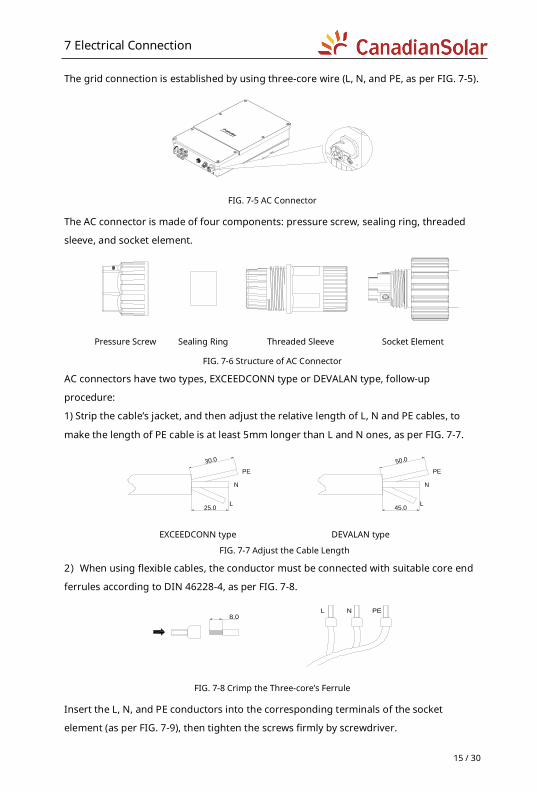
The grid connection is established by using three-core wire (L, N, and PE, as per FIG. 7-5).
FIG. 7-5 AC Connector
The AC connector is made of four components: pressure screw, sealing ring, threaded
sleeve, and socket element.
Pressure Screw Sealing Ring Threaded Sleeve Socket Element
FIG. 7-6 Structure of AC Connector
AC connectors have two types, EXCEEDCONN type or DEVALAN type, follow-up
procedure:
1) Strip the cable’s jacket, and then adjust the relative length of L, N and PE cables, to
make the length of PE cable is at least 5mm longer than L and N ones, as per FIG. 7-7.
30.0
25.0
PE
N
L
50.0
45.0
PE
N
L
EXCEEDCONN type DEVALAN type
FIG. 7-7 Adjust the Cable Length
2)When using flexible cables, the conductor must be connected with suitable core end
ferrules according to DIN 46228-4, as per FIG. 7-8.
8.0L N PE
FIG. 7-8 Crimp the Three-core’s Ferrule
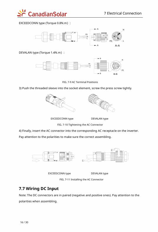
Insert the L, N, and PE conductors into the corresponding terminals of the socket
element (as per FIG. 7-9), then tighten the screws firmly by screwdriver.
7 Electrical Connection
16 / 30
EXCEEDCONN type (Torque 0.8N.m):
PE L
N
LN
PE
A
A A-A
DEVALAN type (Torque 1.4N.m):
LN
PE
B
B B-B
N
PEL
FIG. 7-9 AC Terminal Positions
3) Push the threaded sleeve into the socket element, screw the press screw tightly.
EXCEEDCONN type DEVALAN type
FIG. 7-10 Tightening the AC Connector
4) Finally, insert the AC connector into the corresponding AC receptacle on the inverter.
Pay attention to the polarities to make sure the correct assembling.
2
1
EXCEEDCONN type DEVALAN type
FIG. 7-11 Installing the AC Connector
7.7 Wiring DC Input Note: The DC connectors are in paired (negative and positive ones). Pay attention to the
polarities when assembling.
7 Electrical Connection
17 / 30
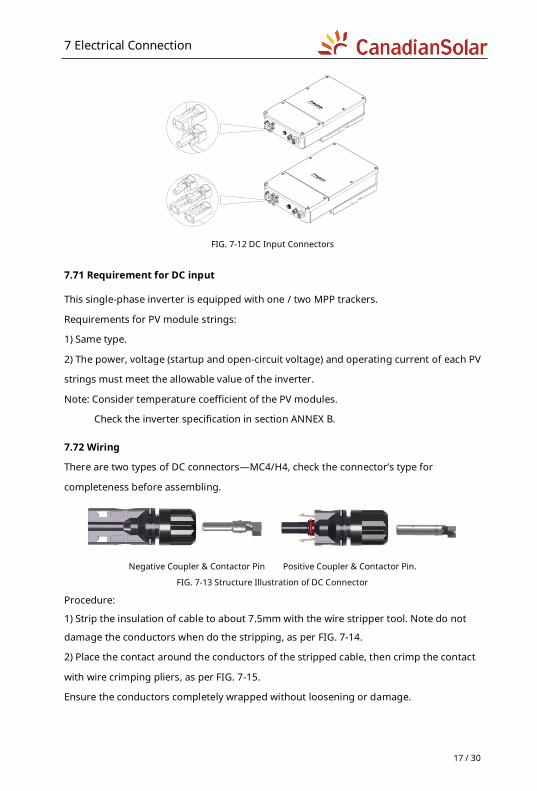
FIG. 7-12 DC Input Connectors
7.71 Requirement for DC input
This single-phase inverter is equipped with one / two MPP trackers.
Requirements for PV module strings:
1) Same type.
2) The power, voltage (startup and open-circuit voltage) and operating current of each PV
strings must meet the allowable value of the inverter.
Note: Consider temperature coefficient of the PV modules.
Check the inverter specification in section ANNEX B.
7.72 Wiring
There are two types of DC connectors—MC4/H4, check the connector’s type for
completeness before assembling.
Negative Coupler & Contactor Pin Positive Coupler & Contactor Pin.
FIG. 7-13 Structure Illustration of DC Connector
Procedure:
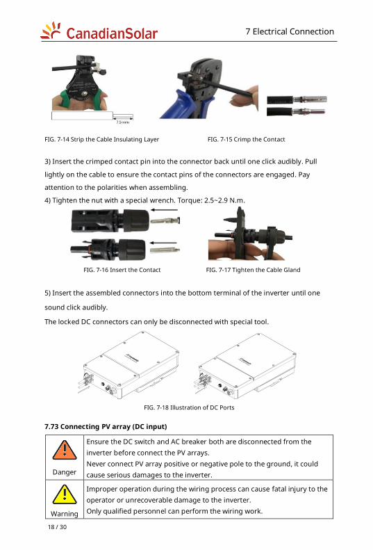
1) Strip the insulation of cable to about 7.5mm with the wire stripper tool. Note do not
damage the conductors when do the stripping, as per FIG. 7-14.
2) Place the contact around the conductors of the stripped cable, then crimp the contact
with wire crimping pliers, as per FIG. 7-15.
Ensure the conductors completely wrapped without loosening or damage.
7 Electrical Connection
18 / 30
FIG. 7-14 Strip the Cable Insulating Layer FIG. 7-15 Crimp the Contact
3) Insert the crimped contact pin into the connector back until one click audibly. Pull
lightly on the cable to ensure the contact pins of the connectors are engaged. Pay
attention to the polarities when assembling.
4) Tighten the nut with a special wrench. Torque: 2.5~2.9 N.m.
FIG. 7-16 Insert the Contact FIG. 7-17 Tighten the Cable Gland
5) Insert the assembled connectors into the bottom terminal of the inverter until one
sound click audibly.
The locked DC connectors can only be disconnected with special tool.
FIG. 7-18 Illustration of DC Ports
7.73 Connecting PV array (DC input)
Danger
Ensure the DC switch and AC breaker both are disconnected from the inverter before connect the PV arrays. Never connect PV array positive or negative pole to the ground, it could cause serious damages to the inverter.
Warning
Improper operation during the wiring process can cause fatal injury to the operator or unrecoverable damage to the inverter. Only qualified personnel can perform the wiring work.
7 Electrical Connection
19 / 30
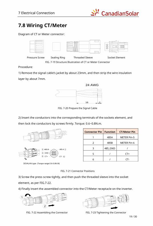
7.8 Wiring CT/Meter Diagram of CT or Meter connector:
Pressure Screw Sealing Ring Threaded Sleeve Socket Element
FIG. 7-19 Structure Illustration of CT or Meter Connector
Procedure:
1) Remove the signal cable’s jacket by about 23mm, and then strip the wire insulation
layer by about 7mm.
16 7
24 AWG
FIG. 7-20 Prepare the Signal Cable
2) Insert the conductors into the corresponding terminals of the sockets element, and
then lock the conductors by screws firmly. Torque: 0.6~0.8N.m.
DEVALAN type (Torque range:0.6-0.8N.M)
485-A485-B
CT-
12
6
GND3
CT+5
FIG. 7-21 Connector Positions
3) Screw the press screw tightly, and then push the threaded sleeve into the socket
element, as per FIG.7-22.
4) Finally insert the assembled connector into the CT/Meter receptacle on the inverter.
1
2
FIG. 7-22 Assembling the Connector FIG. 7-23 Tightening the Connector
Connector Pin Function CT/Meter Pin
1 485A METER Pin-5
2 485B METER Pin-6
3 485_GND /
5 / CT+
6 / CT-
8 Communication
20 / 30
8 Communication
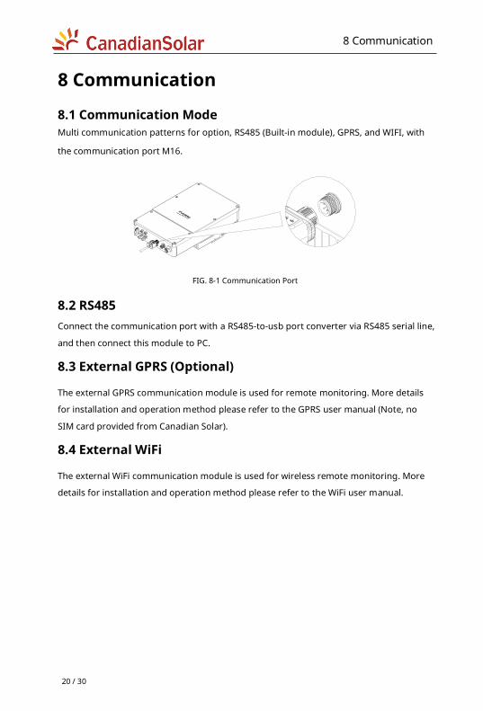
8.1 Communication Mode Multi communication patterns for option, RS485 (Built-in module), GPRS, and WIFI, with
the communication port M16.
FIG. 8-1 Communication Port
8.2 RS485 Connect the communication port with a RS485-to-usb port converter via RS485 serial line,
and then connect this module to PC.
8.3 External GPRS (Optional)
The external GPRS communication module is used for remote monitoring. More details
for installation and operation method please refer to the GPRS user manual (Note, no
SIM card provided from Canadian Solar).
8.4 External WiFi
The external WiFi communication module is used for wireless remote monitoring. More
details for installation and operation method please refer to the WiFi user manual.
9 Commissioning Inverter
21 / 30
9 Commissioning Inverter
9.1 Checking Electrical 1) Check PE connections with multi-meter:
To make sure all the bare metal surfaces of the inverter are grounded.
2) Check DC voltage value:
Check if the DC voltage of the PV string exceeds the allowable range.
3) Check the polarities of the DC voltage:
To make sure the DC polarities are correct.
4) Check the ground insulation of PV array with multi-meter:
Ensure the impedance value of ground insulation is more than 1MOhm.
9.2 Checking Mechanical 1) Ensure the inverter is installed properly, fixed with a Wall-mounting bracket firmly, and
the upper cover is installed correctly.
2) Ensure the AC connectors are installed properly and fixed firmly.
3) Ensure the dust covers are sealed reliably which are used for the empty DC
connectors.
4) Ensure all the cables are connected effectively, fixed firmly, and no visible damages to
the insulation layers.
9.3 Start-UP Inverter After electrical and mechanical inspections, first turn on the AC main switch/breaker,
then turn on the DC switch. The inverter will start automatically when the DC input
voltage meets the performance requirement of the utility grid.
Normally there will be three statuses during the operation (refer to the LED indications):
1) Waiting:
Conditions: The initial DC voltage of the PV strings is greater than the Min. DC input
voltage, but is lower than the DC start-up input voltage.
Inverter cannot start-up normally and cannot feed power into utility grid either.
2) Checking:
Conditions: The initial voltage of the PV strings exceeds the start-up DC input voltage of
the inverter. Meanwhile both the voltage and frequency of the utility grid are normal.
9 Commissioning Inverter
22 / 30
Inverter will check the feeding conditions immediately. If anything wrong during
checking, inverter will switch to the “Fault” mode.
3) Normal:
Conditions: All the checking results are normal.
Inverter will switch to “Normal” mode and feed power into utility grid.
The inverter may turn on and off continuously during the period of low or absent
sunlight due to the shortage of power generated by the PV modules. If such fault occurs
frequently, please contact the maintenance personnel.
Note: For the monitoring and local APP information, please refer to documents
published on our website at: https://monitoring.csisolar.com/platformSelect.
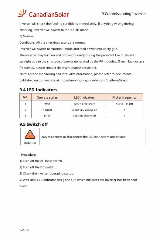
9.4 LED Indicators No. Operate states LED Indicators Flicker frequency
1 Wait Green LED flicker 1s On,1s Off
2 Normal Green LED always on /
3 Error Red LED always on /
9.5 Switch off
DANGER
Never connect or disconnect the DC connectors under load.
Procedure:
1) Turn off the AC main switch.
2) Turn off the DC switch.
3) Check the inverter operating status.
4) Wait until LED indicator has gone out, which indicates the inverter has been shut
down.
10 Daily Maintenance
23 / 30
10 Daily Maintenance
DANGER
Risk of inverter damage or personal injury due to incorrect service!
Always keep in mind that the inverter is powered by dual sources: PV
array and utility grid.
Before any service work, observe the following procedure.
1) Disconnect the inverter from the utility grid side first and then PV
array.
2) Wait at least 5 minutes after shun down the inverter, for inner
capacitors to discharge completely.
3) Verify that no voltage and current existing with appropriate
testing devices.
CAUTION
Keep non-related persons away!
A temporary warning sign or barrier must be posted to keep
non-related persons away while performing electrical connection
and service work.
NOTICE
Risk of inverter damage if it is improperly serviced.
Use accessories and spare parts approved by the inverter
manufacturer only. Never modify the inverter or other components
of the inverter. The loss of any or all warranty rights may follow if
otherwise.
NOTICE
Any malfunction that may impair the inverter safety operation must
be repaired immediately before the inverter is restarted.
Inverter contains no customer serviceable parts inside. Please
contact local authorized personnel if any service work is required.
Information
Servicing of the device in accordance with the manual should never
be undertaken in the absence of proper tools, test equipments or
the more recent revision of the manual with has been clearly and
thoroughly understood.
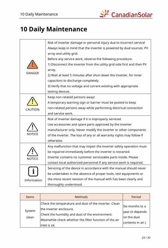
Items Methods Period
System
clean
Check the temperature and dust of the inverter. Clean
the inverter enclosure.
Check the humidity and dust of the environment.
Meanwhile check whether the filter function of the air
inlet is ok.
Six months to a
year (it depends
on the dust
contents in air.)
11 SPD Maintenance
24 / 30
11 SPD Maintenance
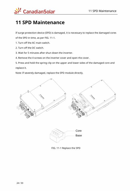
If surge protection device (SPD) is damaged, it is necessary to replace the damaged cores
of the SPD in time, as per FIG. 11-1.
1. Turn off the AC main switch.
2. Turn off the DC switch.
3. Wait for 5 minutes after shun down the inverter.
4. Remove the 4 screws on the inverter cover and open the cover.
5. Press and hold the spring clip on the upper and lower sides of the damaged core and
replace it.
Note: If severely damaged, replace the SPD module directly.
Core
Base
FIG. 11-1 Replace the SPD
12 Trouble Shooting
25 / 30
12 Trouble Shooting
When inverter does not operate normally, we recommend the following actions for quick
troubleshooting. Please review the error list table carefully.
12.1 Warning The different LED colors and flashing status identify the current operation statuses of the
inverter. If the red color is always on, it indicates the inverter fault. Usually the warnings
can be cleared through an orderly shutdown / reset or a self-corrective action performed
by the inverter.
12.2 Errors Error codes identify a possible equipment fault, or incorrect setting/ configuration. Any
and all attempts to correct or clear a fault must be performed by qualified personnel.
Typically, the Errors code can be cleared once the cause or fault is removed.
However, some of the (E) codes may cannot be cleared, in this case please contact the
dealer or Canadian Solar to replace a new one.
Errors as indicated in the table below:
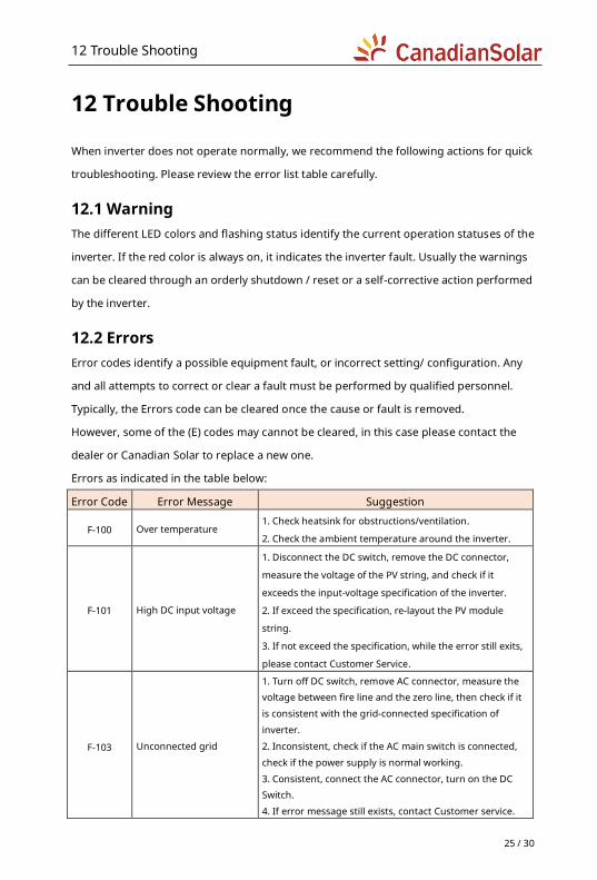
Error Code Error Message Suggestion
F-100 Over temperature 1. Check heatsink for obstructions/ventilation.
2. Check the ambient temperature around the inverter.
F-101 High DC input voltage
1. Disconnect the DC switch, remove the DC connector,
measure the voltage of the PV string, and check if it
exceeds the input-voltage specification of the inverter.
2. If exceed the specification, re-layout the PV module
string.
3. If not exceed the specification, while the error still exits,
please contact Customer Service.
F-103 Unconnected grid
1. Turn off DC switch, remove AC connector, measure the voltage between fire line and the zero line, then check if it
is consistent with the grid-connected specification of
inverter.
2. Inconsistent, check if the AC main switch is connected,
check if the power supply is normal working.
3. Consistent, connect the AC connector, turn on the DC Switch.
4. If error message still exists, contact Customer service.
12 Trouble Shooting
26 / 30
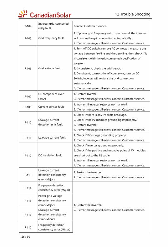
F-104 Inverter grid-connected relay fault
Contact Customer service.
F-105 Grid frequency fault
1. If power grid frequency returns to normal, the inverter
will restore the grid connection automatically.
2. If error message still exists, contact Customer service.
F-106 Grid voltage fault
1. Turn off DC switch, remove AC connector, measure the
voltage between fire line and the zero line, then check if it
is consistent with the grid-connected specification of
inverter.
2. Inconsistent, check the grid layout.
3. Consistent, connect the AC connector, turn on DC
Switch, inverter will restore the grid connection
automatically.
4. If error message still exists, contact Customer service.
F-107 DC component over
range
1. Restart inverter.
2. If error message still exists, contact Customer service.
F-108 Current sensor fault 1. Wait until inverter restores normal work.
2. If error message still exists, contact Customer service.
F-110 Leakage current
detection unit fault
1. Check if there is any PV cable breakage.
2. Check if the PV modules grounding improperly.
3. Restart inverter.
4. If error message still exists, contact Customer service.
F-111 Leakage current fault 1. Check if PV strings grounding properly.
2. If error message still exists, contact Customer service.
F-112 DC insulation fault
1. Check if inverter grounding properly.
2. Check if the positive and negative poles of PV modules
are short out to the PE cable.
3. Wait until inverter restores normal work.
4. If error message still exists, contact Customer service.
F-113
Leakage current detection consistency
error (Major)
1. Restart the inverter.
2. If error message still exists, contact Customer service.
F-114 Frequency detection
consistency error (Major)
1. Restart the inverter.
2. If error message still exists, contact Customer service.
F-115
Power grid voltage
detection consistency
error (Major)
F-116
Leakage current
detection consistency
error (Minor)
F-117 Frequency detection
consistency error (Minor)
13 Handling the Inverter
27 / 30
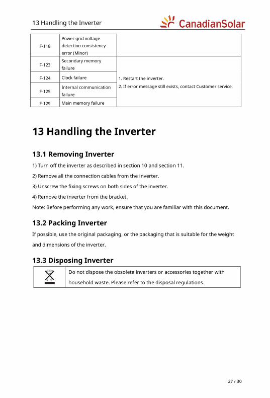
F-118
Power grid voltage detection consistency
error (Minor)
F-123 Secondary memory
failure
1. Restart the inverter.
2. If error message still exists, contact Customer service.
F-124 Clock failure
F-125 Internal communication
failure
F-129 Main memory failure
13 Handling the Inverter
13.1 Removing Inverter 1) Turn off the inverter as described in section 10 and section 11.
2) Remove all the connection cables from the inverter.
3) Unscrew the fixing screws on both sides of the inverter.
4) Remove the inverter from the bracket.
Note: Before performing any work, ensure that you are familiar with this document.
13.2 Packing Inverter If possible, use the original packaging, or the packaging that is suitable for the weight
and dimensions of the inverter.
13.3 Disposing Inverter
Do not dispose the obsolete inverters or accessories together with
household waste. Please refer to the disposal regulations.
ANNEX A: Acronyms and Abbreviations
28 / 30
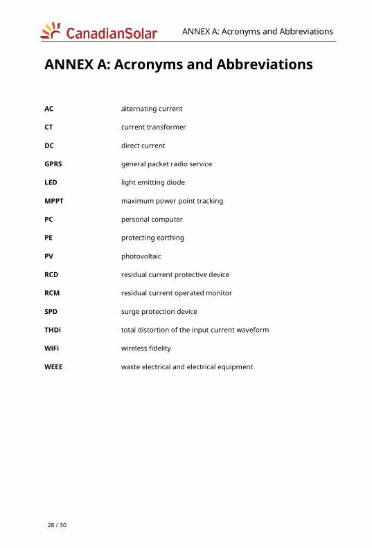
ANNEX A: Acronyms and Abbreviations
AC alternating current
CT current transformer
DC direct current
GPRS general packet radio service
LED light emitting diode
MPPT maximum power point tracking
PC personal computer
PE protecting earthing
PV photovoltaic
RCD residual current protective device
RCM residual current operated monitor
SPD surge protection device
THDi total distortion of the input current waveform
WiFi wireless fidelity
WEEE waste electrical and electrical equipment

ANNEX B: Specification
29 / 30
ANNEX B: Specification Model CSI-3K-S22002-ED CSI-5K-S22002-ED
Input (DC)
Max. DC Input Power (W) 4080 6500
Max. DC Input Voltage (V) 600 600
Startup DC Input Voltage (V) 60 110
MPPT Operating Voltage Range (V) 60 ~ 500 100 ~ 550
Rated Input Voltage (V) 360 360
Max. Input Current (A) 12 12 / 12
Max. Short-Circuit Current (A) 15 15 / 15
Number of MPP Trackers 1 2
Number of DC Inputs 1 / 1 1 / 1
Output (AC)
Rated Output Power (W) 3000 5000
AC Grid Connection Type L / N / PE
AC Nominal Voltage And Range (V) 220 / 230 / 240 (180 ~ 280)
AC Nominal Frequency And Range (Hz) 50 / 60 ( ±5 )
Max. Output Current (A) 13.6 25
Power Factor(@ Rated Output Power) > 0.99
Displacement Power Factor 0.8 leading to 0.8 lagging
Total Harmonic Distortion (THDi) < 3%
Efficiency
Max. Efficiency 97.8 % 98.0 %
European Efficiency 97.1 % 97.5 %
MPPT Efficiency 99.9 % 99.9 %
Safety & Protection
DC SPD Type II
DC Switch Integrated
Anti-Islanding Protection Integrated
DC Reverse-Protection Integrated
Insulation Monitoring Integrated
AC Over Voltage Protection Integrated
AC Over Current Protection Integrated
AC Short-Circuit Protection Integrated
Residual Current Protection Integrated
Overvoltage Class ll (DC), lll (AC)
General Parameters
Dimensions (W × H × D, mm) 312 x 517 x 156 355 x 572 x 158
Net Weight (kg) 10 15
ANNEX B: Specification
30 / 30
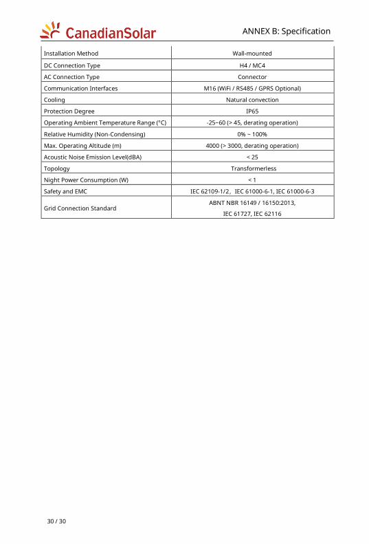
Installation Method Wall-mounted
DC Connection Type H4 / MC4
AC Connection Type Connector
Communication Interfaces M16 (WiFi / RS485 / GPRS Optional)
Cooling Natural convection
Protection Degree IP65
Operating Ambient Temperature Range (°C) -25~60 (> 45, derating operation)
Relative Humidity (Non-Condensing) 0% ~ 100%
Max. Operating Altitude (m) 4000 (> 3000, derating operation)
Acoustic Noise Emission Level(dBA) < 25
Topology Transformerless
Night Power Consumption (W) < 1
Safety and EMC IEC 62109-1/2,IEC 61000-6-1, IEC 61000-6-3
Grid Connection Standard ABNT NBR 16149 / 16150:2013,
IEC 61727, IEC 62116

Canada – Global Headquarters
Canadian Solar Inc.
545 Speedvale Avenue West, Guelph, Ontario, N1K 1E6
P +1 519 837 1881
F +1 519 837 2550
Sales Inquiries Email: [email protected]
Customer Support Email: [email protected]
This manual is subject to change without prior notification. Copyright is reserved.
Duplication of any part of this issue is prohibited without written permission.