Embed Size (px)
DESCRIPTION
4. Pure Bending Basit Eğilme. Pure Bending Other Loading Types Symmetric Member in Pure Bending Bending Deformations Strain Due to Bending Beam Section Properties Properties of American Standard Shapes Deformations in a Transverse Cross Section Sample Problem 4.2 - PowerPoint PPT Presentation
Citation preview

MECHANICS OF MATERIALS
Third Edition
Ferdinand P. Beer
E. Russell Johnston, Jr.
John T. DeWolf
Lecture Notes:
J. Walt Oler
Texas Tech University
CHAPTER
© 2002 The McGraw-Hill Companies, Inc. All rights reserved.
4 Pure Bending
Basit Eğilme

© 2002 The McGraw-Hill Companies, Inc. All rights reserved.
MECHANICS OF MATERIALS
Th
irdE
ditio
n
Beer • Johnston • DeWolf
4 - 2
Pure BendingPure Bending
Other Loading Types
Symmetric Member in Pure Bending
Bending Deformations
Strain Due to Bending
Beam Section Properties
Properties of American Standard Shapes
Deformations in a Transverse Cross Section
Sample Problem 4.2
Bending of Members Made of Several Materials
Example 4.03
Reinforced Concrete Beams
Sample Problem 4.4
Stress Concentrations
Plastic Deformations
Members Made of an Elastoplastic Material
Example 4.03
Reinforced Concrete Beams
Sample Problem 4.4
Stress Concentrations
Plastic Deformations
Members Made of an Elastoplastic Material
Plastic Deformations of Members With a Single Plane of S...
Residual Stresses
Example 4.05, 4.06
Eccentric Axial Loading in a Plane of Symmetry
Example 4.07
Sample Problem 4.8
Unsymmetric Bending
Example 4.08
General Case of Eccentric Axial Loading
© 2002 The McGraw-Hill Companies, Inc. All rights reserved.
MECHANICS OF MATERIALS
Th
irdE
ditio
n
Beer • Johnston • DeWolf
4 - 3
Photo 4.3 Wide-flange steel beams form the frame of many buildings.

© 2002 The McGraw-Hill Companies, Inc. All rights reserved.
MECHANICS OF MATERIALS
Th
irdE
ditio
n
Beer • Johnston • DeWolf
4 - 4
Pure Bending
Pure Bending: Prismatic members subjected to equal and opposite couples acting in the same longitudinal plane

© 2002 The McGraw-Hill Companies, Inc. All rights reserved.
MECHANICS OF MATERIALS
Th
irdE
ditio
n
Beer • Johnston • DeWolf
4 - 5
Other Loading Types
• Eccentric Loading: Axial loading which does not pass through section centroid produces internal forces equivalent to an axial force and a couple
Photo 4.2 Clamp used to glue lumber pieces together.

© 2002 The McGraw-Hill Companies, Inc. All rights reserved.
MECHANICS OF MATERIALS
Th
irdE
ditio
n
Beer • Johnston • DeWolf
4 - 6
Other Loading Types
• Principle of Superposition: The normal stress due to pure bending may be combined with the normal stress due to axial loading and shear stress due to shear loading to find the complete state of stress.
• Transverse Loading: Concentrated or distributed transverse load produces internal forces equivalent to a shear force and a couple

© 2002 The McGraw-Hill Companies, Inc. All rights reserved.
MECHANICS OF MATERIALS
Th
irdE
ditio
n
Beer • Johnston • DeWolf
4 - 7
Symmetric Member in Pure Bending
• Internal forces in any cross section are
equivalent to a couple. The moment of the
couple is the section bending moment.
• From statics, a couple M consists of two equal
and opposite forces.
• The sum of the components of the forces in any
direction is zero.

© 2002 The McGraw-Hill Companies, Inc. All rights reserved.
MECHANICS OF MATERIALS
Th
irdE
ditio
n
Beer • Johnston • DeWolf
4 - 8
Symmetric Member in Pure Bending
MM
MdAyM
dAzM
dAF
z
zxz
xy
xx
0
0
• The moment is the same about any axis
perpendicular to the plane of the couple and zero
about any axis contained in the plane.
• These requirements may be applied to the sums
of the components and moments of the statically
indeterminate elementary internal forces.

© 2002 The McGraw-Hill Companies, Inc. All rights reserved.
MECHANICS OF MATERIALS
Th
irdE
ditio
n
Beer • Johnston • DeWolf
4 - 9
Bending Deformations
• member remains symmetric
• bends uniformly to form a circular arc
• cross-sectional plane passes through arc
center and remains planar
• length of top decreases and length of
bottom increases
Beam with a plane of symmetry in pure bending:

© 2002 The McGraw-Hill Companies, Inc. All rights reserved.
MECHANICS OF MATERIALS
Th
irdE
ditio
n
Beer • Johnston • DeWolf
4 - 10
Bending Deformations
• a neutral surface must exist that is parallel
to the upper and lower surfaces and for
which the length does not change
• stresses and strains are negative
(compressive) above the neutral plane and
positive (tension) below it

© 2002 The McGraw-Hill Companies, Inc. All rights reserved.
MECHANICS OF MATERIALS
Th
irdE
ditio
n
Beer • Johnston • DeWolf
4 - 11
Strain Due to Bending
Consider a beam segment of length L. After
deformation, the length of the neutral surface
remains L. At other sections,
Strain varies linearly
yyLL
yLJK
LDE
mx
mm
x
c
yc
ρc
yy
L
or

© 2002 The McGraw-Hill Companies, Inc. All rights reserved.
MECHANICS OF MATERIALS
Th
irdE
ditio
n
Beer • Johnston • DeWolf
4 - 12
Stress Due to Bending
• For a linearly elastic material,
linearly) varies(stress
mmxx c
y
c
yEE
• For static equilibrium,
0
0
dAyc
dAc
ydAF
m
mxx
First moment with respect to neutral plane is zero. Therefore, the neutral surface must pass through the section centroid.
• For static equilibrium,
zx
mx
m
mm
mx
z
III
Myc
yS
M
I
Mcc
IdAy
cM
dAc
yydAyM
M
where
ngSubstituti
0
2
MM z
y
EE xx

© 2002 The McGraw-Hill Companies, Inc. All rights reserved.
MECHANICS OF MATERIALS
Th
irdE
ditio
n
Beer • Johnston • DeWolf
4 - 13
Bending Radius Due to Bending
• For a linearly elastic material,
zx III
My where
MM z
y
EE xx
I
yMyE
EI
M
1
Curvature
Bending RadiusM
EI
Bending Rigidity:EI

© 2002 The McGraw-Hill Companies, Inc. All rights reserved.
MECHANICS OF MATERIALS
Th
irdE
ditio
n
Beer • Johnston • DeWolf
4 - 14
Beam Section Properties
modulussection
inertia ofmoment section
c
IS
IS
M
I
Mcm
• A beam section with a larger section modulus will have a lower maximum stress
• Consider a rectangular beam cross section,
AhbhS
h
bh
c
IS
6
1
6
1 3
21
3121
• The maximum normal stress due to bending,

© 2002 The McGraw-Hill Companies, Inc. All rights reserved.
MECHANICS OF MATERIALS
Th
irdE
ditio
n
Beer • Johnston • DeWolf
4 - 15
Beam Section Properties
• Between two beams with the same cross
sectional area, the beam with the greater
depth will be more effective in resisting
bending.
• Structural steel beams are designed to
have a large section modulus.

© 2002 The McGraw-Hill Companies, Inc. All rights reserved.
MECHANICS OF MATERIALS
Th
irdE
ditio
n
Beer • Johnston • DeWolf
4 - 16
Properties of American Standard Shapes

© 2002 The McGraw-Hill Companies, Inc. All rights reserved.
MECHANICS OF MATERIALS
Th
irdE
ditio
n
Beer • Johnston • DeWolf
4 - 17
Deformations in a Transverse Cross Section• Deformation due to bending moment M is
quantified by the curvature of the neutral surface
• Although cross sectional planes remain planar when subjected to bending moments, in-plane deformations are nonzero,
yy
xzxy
• Expansion above the neutral surface and contraction below it cause an in-plane curvature,
curvature canticlasti :1
EI
M
I
Mc
EcEccmm
111

© 2002 The McGraw-Hill Companies, Inc. All rights reserved.
MECHANICS OF MATERIALS
Th
irdE
ditio
n
Beer • Johnston • DeWolf
4 - 18
Sample Problem 4.2
A cast-iron machine part is acted upon by a 3 kN-m couple. Knowing E = 165 GPa and neglecting the effects of fillets, determine
a)the maximum tensile and compressive stresses,
b)the radius of curvature.

© 2002 The McGraw-Hill Companies, Inc. All rights reserved.
MECHANICS OF MATERIALS
Th
irdE
ditio
n
Beer • Johnston • DeWolf
4 - 19
SOLUTION:
• Based on the cross section geometry, calculate the location of the section centroid and moment of inertia.
2dAIIA
AyY x
• Apply the elastic flexural formula to find the maximum tensile and compressive stresses.
I
yM
I
yM
x
xz
• Calculate the curvature
EI
M
1

© 2002 The McGraw-Hill Companies, Inc. All rights reserved.
MECHANICS OF MATERIALS
Th
irdE
ditio
n
Beer • Johnston • DeWolf
4 - 20
Sample Problem 4.2SOLUTION:
Based on the cross section geometry, calculate the location of the section centroid and moment of inertia.
mm 383000
10114 3
A
AyY
3
3
3
32
101143000
104220120030402
109050180090201
mm ,mm ,mm Area,
AyA
Ayy
49-43
2312123
121
231212
m10868 mm10868
18120040301218002090
x
yyx
II
dAbhdAII

© 2002 The McGraw-Hill Companies, Inc. All rights reserved.
MECHANICS OF MATERIALS
Th
irdE
ditio
n
Beer • Johnston • DeWolf
4 - 21
Sample Problem 4.2
• Apply the elastic flexural formula to find the maximum tensile and compressive stresses.
43
6
43
6
6
10868
38103
10868
22103
1033
mm
mmNmm
I
cM
mm
mmNmm
I
cM
I
yM
NmmkNmMM
BB
AA
x
MPa 0.76A
MPa 3.131B
• Calculate the curvature
433
6
mm10868MPa 10165
mmN 1031
EI
M
mmmmm.ρ
- 74.47477401095201 16

© 2002 The McGraw-Hill Companies, Inc. All rights reserved.
MECHANICS OF MATERIALS
Th
irdE
ditio
n
Beer • Johnston • DeWolf
4 - 22

© 2002 The McGraw-Hill Companies, Inc. All rights reserved.
MECHANICS OF MATERIALS
Th
irdE
ditio
n
Beer • Johnston • DeWolf
4 - 23
© 2002 The McGraw-Hill Companies, Inc. All rights reserved.
MECHANICS OF MATERIALS
Th
irdE
ditio
n
Beer • Johnston • DeWolf
4 - 24

© 2002 The McGraw-Hill Companies, Inc. All rights reserved.
MECHANICS OF MATERIALS
Th
irdE
ditio
n
Beer • Johnston • DeWolf
4 - 25

© 2002 The McGraw-Hill Companies, Inc. All rights reserved.
MECHANICS OF MATERIALS
Th
irdE
ditio
n
Beer • Johnston • DeWolf
4 - 26

© 2002 The McGraw-Hill Companies, Inc. All rights reserved.
MECHANICS OF MATERIALS
Th
irdE
ditio
n
Beer • Johnston • DeWolf
4 - 27

© 2002 The McGraw-Hill Companies, Inc. All rights reserved.
MECHANICS OF MATERIALS
Th
irdE
ditio
n
Beer • Johnston • DeWolf
4 - 28

© 2002 The McGraw-Hill Companies, Inc. All rights reserved.
MECHANICS OF MATERIALS
Th
irdE
ditio
n
Beer • Johnston • DeWolf
4 - 29

© 2002 The McGraw-Hill Companies, Inc. All rights reserved.
MECHANICS OF MATERIALS
Th
irdE
ditio
n
Beer • Johnston • DeWolf
4 - 30

© 2002 The McGraw-Hill Companies, Inc. All rights reserved.
MECHANICS OF MATERIALS
Th
irdE
ditio
n
Beer • Johnston • DeWolf
4 - 31

© 2002 The McGraw-Hill Companies, Inc. All rights reserved.
MECHANICS OF MATERIALS
Th
irdE
ditio
n
Beer • Johnston • DeWolf
4 - 32

© 2002 The McGraw-Hill Companies, Inc. All rights reserved.
MECHANICS OF MATERIALS
Th
irdE
ditio
n
Beer • Johnston • DeWolf
4 - 33

© 2002 The McGraw-Hill Companies, Inc. All rights reserved.
MECHANICS OF MATERIALS
Th
irdE
ditio
n
Beer • Johnston • DeWolf
4 - 34

© 2002 The McGraw-Hill Companies, Inc. All rights reserved.
MECHANICS OF MATERIALS
Th
irdE
ditio
n
Beer • Johnston • DeWolf
4 - 35

© 2002 The McGraw-Hill Companies, Inc. All rights reserved.
MECHANICS OF MATERIALS
Th
irdE
ditio
n
Beer • Johnston • DeWolf
4 - 36

© 2002 The McGraw-Hill Companies, Inc. All rights reserved.
MECHANICS OF MATERIALS
Th
irdE
ditio
n
Beer • Johnston • DeWolf
4 - 37

© 2002 The McGraw-Hill Companies, Inc. All rights reserved.
MECHANICS OF MATERIALS
Th
irdE
ditio
n
Beer • Johnston • DeWolf
4 - 38

© 2002 The McGraw-Hill Companies, Inc. All rights reserved.
MECHANICS OF MATERIALS
Th
irdE
ditio
n
Beer • Johnston • DeWolf
4 - 39

© 2002 The McGraw-Hill Companies, Inc. All rights reserved.
MECHANICS OF MATERIALS
Th
irdE
ditio
n
Beer • Johnston • DeWolf
4 - 40

© 2002 The McGraw-Hill Companies, Inc. All rights reserved.
MECHANICS OF MATERIALS
Th
irdE
ditio
n
Beer • Johnston • DeWolf
4 - 41

© 2002 The McGraw-Hill Companies, Inc. All rights reserved.
MECHANICS OF MATERIALS
Th
irdE
ditio
n
Beer • Johnston • DeWolf
4 - 42

© 2002 The McGraw-Hill Companies, Inc. All rights reserved.
MECHANICS OF MATERIALS
Th
irdE
ditio
n
Beer • Johnston • DeWolf
4 - 43
© 2002 The McGraw-Hill Companies, Inc. All rights reserved.
MECHANICS OF MATERIALS
Th
irdE
ditio
n
Beer • Johnston • DeWolf
4 - 44

© 2002 The McGraw-Hill Companies, Inc. All rights reserved.
MECHANICS OF MATERIALS
Th
irdE
ditio
n
Beer • Johnston • DeWolf
4 - 45

© 2002 The McGraw-Hill Companies, Inc. All rights reserved.
MECHANICS OF MATERIALS
Th
irdE
ditio
n
Beer • Johnston • DeWolf
4 - 46

© 2002 The McGraw-Hill Companies, Inc. All rights reserved.
MECHANICS OF MATERIALS
Th
irdE
ditio
n
Beer • Johnston • DeWolf
4 - 47

© 2002 The McGraw-Hill Companies, Inc. All rights reserved.
MECHANICS OF MATERIALS
Th
irdE
ditio
n
Beer • Johnston • DeWolf
4 - 48

© 2002 The McGraw-Hill Companies, Inc. All rights reserved.
MECHANICS OF MATERIALS
Th
irdE
ditio
n
Beer • Johnston • DeWolf
4 - 49
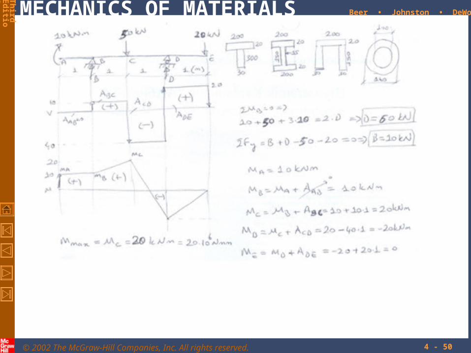
Example: Yükleme durumu ve kesiti görülen kiriş için “n”;
a)Mesnet tepkilerini bulunuz.
b)KKD ve EMD diyagramını çiziniz.
c)Kesitin ağırlık merkezinin yerini bulunuz.
d)Ağırlık merkezinden geçen yatay eksene göre kesitin atalet momentini bulunuz.
e)Kesitin en üst ve altındaki gerilmeleri hesaplayınız.
f) σak =150 MPa olduğuna göre EK=3 alarak kirişin emniyetli olup olmadığını irdeleyiniz.
© 2002 The McGraw-Hill Companies, Inc. All rights reserved.
MECHANICS OF MATERIALS
Th
irdE
ditio
n
Beer • Johnston • DeWolf
4 - 50

© 2002 The McGraw-Hill Companies, Inc. All rights reserved.
MECHANICS OF MATERIALS
Th
irdE
ditio
n
Beer • Johnston • DeWolf
4 - 51

© 2002 The McGraw-Hill Companies, Inc. All rights reserved.
MECHANICS OF MATERIALS
Th
irdE
ditio
n
Beer • Johnston • DeWolf
4 - 52

© 2002 The McGraw-Hill Companies, Inc. All rights reserved.
MECHANICS OF MATERIALS
Th
irdE
ditio
n
Beer • Johnston • DeWolf
4 - 53
Bending of Members Made of Several Materials• Consider a composite beam formed from
two materials with E1 and E2.
• Normal strain varies linearly.
y
x
• Piecewise linear normal stress variation.
yE
EyE
E xx2
221
11
Neutral axis does not pass through section centroid of composite section.
• Elemental forces on the section are
dAyE
dAdFdAyE
dAdF
222
111
1
2112 E
EndAn
yEdA
ynEdF
• Define a transformed section such that
xx
x
nI
My
21
© 2002 The McGraw-Hill Companies, Inc. All rights reserved.
MECHANICS OF MATERIALS
Th
irdE
ditio
n
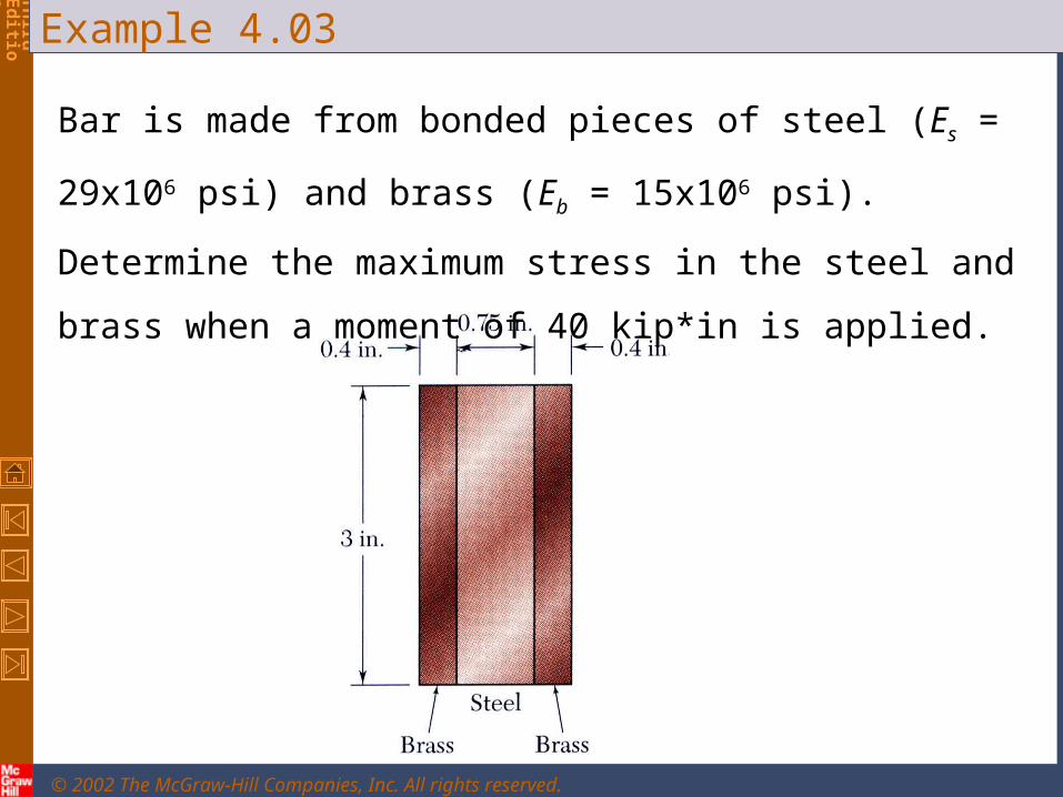
Beer • Johnston • DeWolfExample 4.03
Bar is made from bonded pieces of steel (Es = 29x106 psi) and
brass (Eb = 15x106 psi). Determine the maximum stress in the steel
and brass when a moment of 40 kip*in is applied.
© 2002 The McGraw-Hill Companies, Inc. All rights reserved.
MECHANICS OF MATERIALS
Th
irdE
ditio
n
Beer • Johnston • DeWolf
4 - 554 - 55
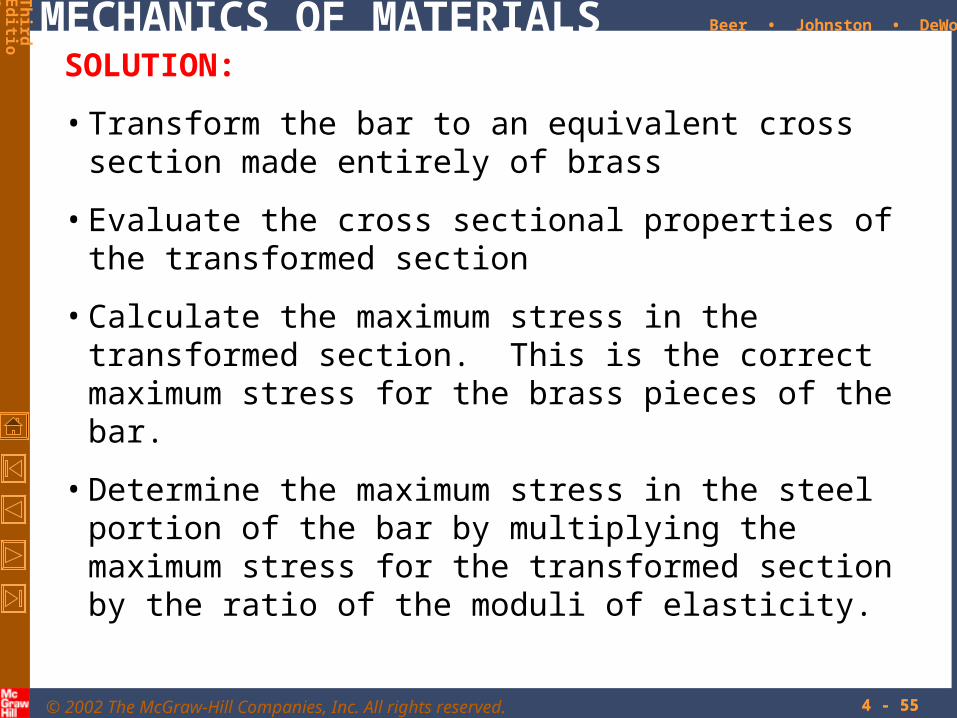
SOLUTION:
• Transform the bar to an equivalent cross section made entirely of brass
• Evaluate the cross sectional properties of the transformed section
• Calculate the maximum stress in the transformed section. This is the correct maximum stress for the brass pieces of the bar.
• Determine the maximum stress in the steel portion of the bar by multiplying the maximum stress for the transformed section by the ratio of the moduli of elasticity.

© 2002 The McGraw-Hill Companies, Inc. All rights reserved.
MECHANICS OF MATERIALS
Th
irdE
ditio
n
Beer • Johnston • DeWolf
4 - 56
Example 4.03
• Evaluate the transformed cross sectional properties
4
31213
121
in 063.5
in 3in. 25.2
hbI T
• Transform the bar to an equivalent cross section made entirely of brass.
in 25.2in 4.0in 75.0933.1in 4.0
933.1psi1015
psi10296
6
T
b
s
b
E
En

© 2002 The McGraw-Hill Companies, Inc. All rights reserved.
MECHANICS OF MATERIALS
Th
irdE
ditio
n
Beer • Johnston • DeWolf
4 - 57
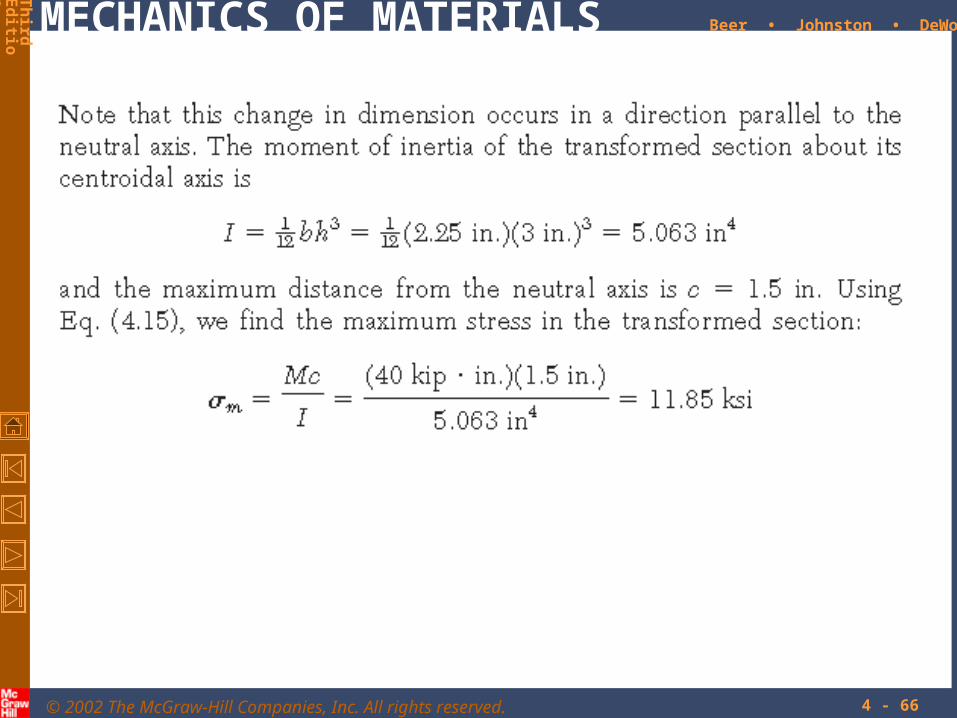
Example 4.03
• Calculate the maximum stresses
ksi 85.11
in 5.063
in 5.1inkip 404
I
Mcm
ksi 85.11933.1max
max
ms
mb
n
ksi 22.9
ksi 85.11
max
max
s
b

© 2002 The McGraw-Hill Companies, Inc. All rights reserved.
MECHANICS OF MATERIALS
Th
irdE
ditio
n
Beer • Johnston • DeWolf
4 - 58
Reinforced Concrete Beams• Concrete beams subjected to bending moments are
reinforced by steel rods.
• The steel rods carry the entire tensile load below the neutral surface. The upper part of the concrete beam carries the compressive load.
• In the transformed section, the cross sectional area of the steel, As, is replaced by the equivalent areanAs where n = Es/Ec.
• To determine the location of the neutral axis,
0
022
21
dAnxAnxb
xdAnx
bx
ss
s
• The normal stress in the concrete and steel
xsxc
x
nI
My

© 2002 The McGraw-Hill Companies, Inc. All rights reserved.
MECHANICS OF MATERIALS
Th
irdE
ditio
n
Beer • Johnston • DeWolf
4 - 59
Sample Problem 4.4
A concrete floor slab is reinforced with 5/8-in-diameter steel rods.
The modulus of elasticity is 29x106psi for steel and 3.6x10⁶psi for
concrete. With an applied bending moment of 40 kip*in for 1-ft
width of the slab, determine the maximum stress in the concrete and
steel.

© 2002 The McGraw-Hill Companies, Inc. All rights reserved.
MECHANICS OF MATERIALS
Th
irdE
ditio
n
Beer • Johnston • DeWolf
4 - 60
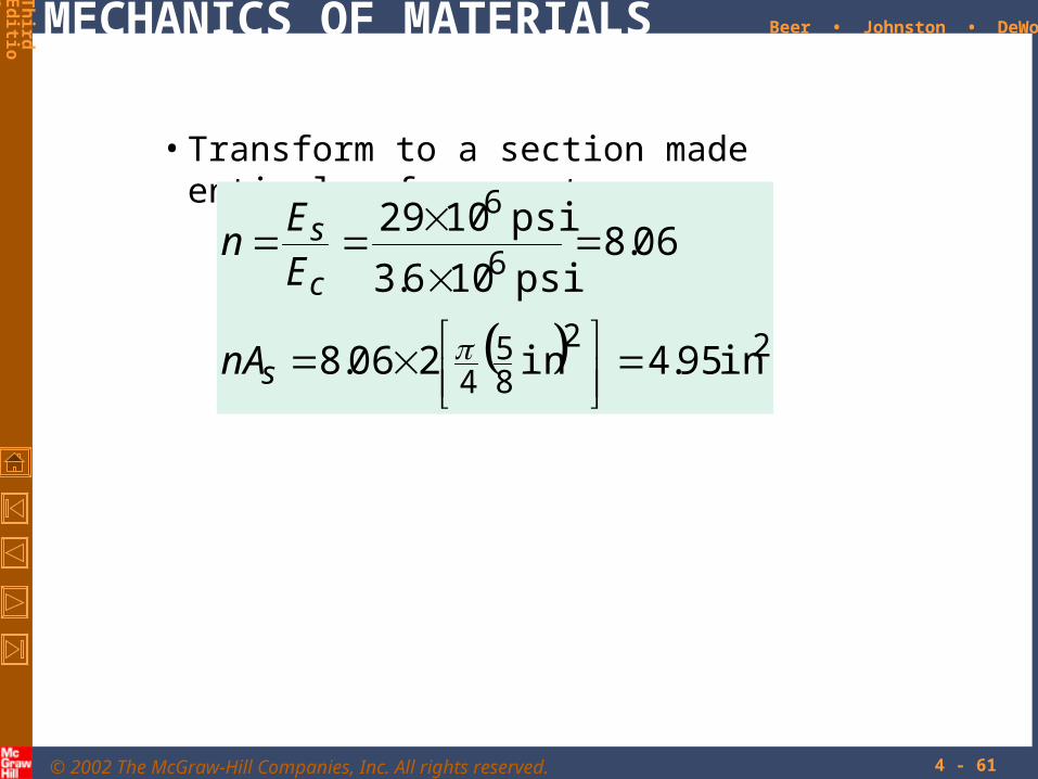
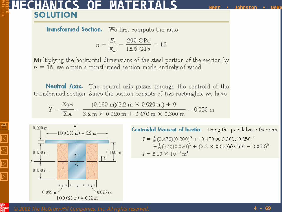
SOLUTION:
• Transform to a section made entirely of concrete.
• Evaluate geometric properties of transformed section.
• Calculate the maximum stresses in the concrete and steel.
© 2002 The McGraw-Hill Companies, Inc. All rights reserved.
MECHANICS OF MATERIALS
Th
irdE
ditio
n
Beer • Johnston • DeWolf
4 - 61
• Transform to a section made entirely of concrete.
22
85
4
6
6
in95.4in 206.8
06.8psi 106.3
psi 1029
s
c
s
nA
E
En

© 2002 The McGraw-Hill Companies, Inc. All rights reserved.
MECHANICS OF MATERIALS
Th
irdE
ditio
n
Beer • Johnston • DeWolf
4 - 62
Solution
• Evaluate the geometric properties of the transformed section.
422331 in4.44in55.2in95.4in45.1in12
in450.10495.42
12
I
xxx
x

© 2002 The McGraw-Hill Companies, Inc. All rights reserved.
MECHANICS OF MATERIALS
Th
irdE
ditio
n
Beer • Johnston • DeWolf
4 - 63
• Calculate the maximum stresses.
42
41
in44.4
in55.2inkip4006.8
in44.4
in1.45inkip40
I
Mcn
I
Mc
s
c
ksi306.1c
ksi52.18s

© 2002 The McGraw-Hill Companies, Inc. All rights reserved.
MECHANICS OF MATERIALS
Th
irdE
ditio
n
Beer • Johnston • DeWolf
4 - 64

© 2002 The McGraw-Hill Companies, Inc. All rights reserved.
MECHANICS OF MATERIALS
Th
irdE
ditio
n
Beer • Johnston • DeWolf
4 - 65
© 2002 The McGraw-Hill Companies, Inc. All rights reserved.
MECHANICS OF MATERIALS
Th
irdE
ditio
n
Beer • Johnston • DeWolf
4 - 66

© 2002 The McGraw-Hill Companies, Inc. All rights reserved.
MECHANICS OF MATERIALS
Th
irdE
ditio
n
Beer • Johnston • DeWolf
4 - 67

© 2002 The McGraw-Hill Companies, Inc. All rights reserved.
MECHANICS OF MATERIALS
Th
irdE
ditio
n
Beer • Johnston • DeWolf
4 - 68
© 2002 The McGraw-Hill Companies, Inc. All rights reserved.
MECHANICS OF MATERIALS
Th
irdE
ditio
n
Beer • Johnston • DeWolf
4 - 69

© 2002 The McGraw-Hill Companies, Inc. All rights reserved.
MECHANICS OF MATERIALS
Th
irdE
ditio
n
Beer • Johnston • DeWolf
4 - 70

© 2002 The McGraw-Hill Companies, Inc. All rights reserved.
MECHANICS OF MATERIALS
Th
irdE
ditio
n
Beer • Johnston • DeWolf
4 - 71

© 2002 The McGraw-Hill Companies, Inc. All rights reserved.
MECHANICS OF MATERIALS
Th
irdE
ditio
n
Beer • Johnston • DeWolf
4 - 72

© 2002 The McGraw-Hill Companies, Inc. All rights reserved.
MECHANICS OF MATERIALS
Th
irdE
ditio
n
Beer • Johnston • DeWolf
4 - 73

© 2002 The McGraw-Hill Companies, Inc. All rights reserved.
MECHANICS OF MATERIALS
Th
irdE
ditio
n
Beer • Johnston • DeWolf
4 - 74

© 2002 The McGraw-Hill Companies, Inc. All rights reserved.
MECHANICS OF MATERIALS
Th
irdE
ditio
n
Beer • Johnston • DeWolf
4 - 75

© 2002 The McGraw-Hill Companies, Inc. All rights reserved.
MECHANICS OF MATERIALS
Th
irdE
ditio
n
Beer • Johnston • DeWolf
4 - 76

© 2002 The McGraw-Hill Companies, Inc. All rights reserved.
MECHANICS OF MATERIALS
Th
irdE
ditio
n
Beer • Johnston • DeWolf
4 - 77

© 2002 The McGraw-Hill Companies, Inc. All rights reserved.
MECHANICS OF MATERIALS
Th
irdE
ditio
n
Beer • Johnston • DeWolf
4 - 78

© 2002 The McGraw-Hill Companies, Inc. All rights reserved.
MECHANICS OF MATERIALS
Th
irdE
ditio
n
Beer • Johnston • DeWolf
4 - 79

© 2002 The McGraw-Hill Companies, Inc. All rights reserved.
MECHANICS OF MATERIALS
Th
irdE
ditio
n
Beer • Johnston • DeWolf
4 - 80

© 2002 The McGraw-Hill Companies, Inc. All rights reserved.
MECHANICS OF MATERIALS
Th
irdE
ditio
n
Beer • Johnston • DeWolf
4 - 81

© 2002 The McGraw-Hill Companies, Inc. All rights reserved.
MECHANICS OF MATERIALS
Th
irdE
ditio
n
Beer • Johnston • DeWolf
4 - 82

© 2002 The McGraw-Hill Companies, Inc. All rights reserved.
MECHANICS OF MATERIALS
Th
irdE
ditio
n
Beer • Johnston • DeWolf
4 - 83

© 2002 The McGraw-Hill Companies, Inc. All rights reserved.
MECHANICS OF MATERIALS
Th
irdE
ditio
n
Beer • Johnston • DeWolf
4 - 84

© 2002 The McGraw-Hill Companies, Inc. All rights reserved.
MECHANICS OF MATERIALS
Th
irdE
ditio
n
Beer • Johnston • DeWolf
4 - 85

© 2002 The McGraw-Hill Companies, Inc. All rights reserved.
MECHANICS OF MATERIALS
Th
irdE
ditio
n
Beer • Johnston • DeWolf
4 - 86

© 2002 The McGraw-Hill Companies, Inc. All rights reserved.
MECHANICS OF MATERIALS
Th
irdE
ditio
n
Beer • Johnston • DeWolf
4 - 87
• Stress due to eccentric loading found by superposing the uniform stress due to a centric load and linear stress distribution due a pure bending moment
I
My
A
P
xxx
bendingcentric
Eccentric Axial Loading in a Plane of Symmetry
• Eccentric loading
PdM
PF
• Validity requires stresses below proportional limit, deformations have negligible effect on geometry, and stresses not evaluated near points of load application.

© 2002 The McGraw-Hill Companies, Inc. All rights reserved.
MECHANICS OF MATERIALS
Th
irdE
ditio
n
Beer • Johnston • DeWolf
4 - 88
Example 4.07
An open-link chain is obtained by bending
low-carbon steel rods into the shape shown.
For 160 lb load, determine (a) maximum
tensile and compressive stresses, (b) distance
between section centroid and neutral axis

© 2002 The McGraw-Hill Companies, Inc. All rights reserved.
MECHANICS OF MATERIALS
Th
irdE
ditio
n
Beer • Johnston • DeWolf
4 - 89
SOLUTION:
• Find the equivalent centric load and bending moment
• Superpose the uniform stress due to the centric load and the linear stress due to the bending moment.
• Evaluate the maximum tensile and compressive stresses at the inner and outer edges, respectively, of the superposed stress distribution.
• Find the neutral axis by determining the location where the normal stress is zero.

© 2002 The McGraw-Hill Companies, Inc. All rights reserved.
MECHANICS OF MATERIALS
Th
irdE
ditio
n
Beer • Johnston • DeWolf
4 - 90
Example 4.07
• Equivalent centric load and bending moment
inlb104
in6.0lb160
lb160
PdM
P
psi815
in1963.0
lb160
in1963.0
in25.0
20
2
22
A
P
cA
• Normal stress due to a centric load
psi8475
in10068.
in25.0inlb104
in10068.3
25.0
43
43
4414
41
I
Mc
cI
m
• Normal stress due to bending moment

© 2002 The McGraw-Hill Companies, Inc. All rights reserved.
MECHANICS OF MATERIALS
Th
irdE
ditio
n
Beer • Johnston • DeWolf
4 - 91
Example 4.07
• Maximum tensile and compressive stresses
8475815
8475815
0
0
mc
mt
psi9260t
psi7660c
• Neutral axis location
inlb105
in10068.3psi815
0
43
0
0
M
I
A
Py
I
My
A
P
in0240.00 y

© 2002 The McGraw-Hill Companies, Inc. All rights reserved.
MECHANICS OF MATERIALS
Th
irdE
ditio
n
Beer • Johnston • DeWolf
4 - 92
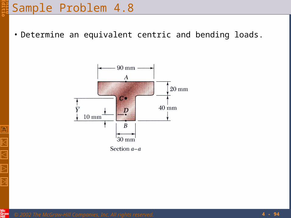
Sample Problem 4.8
The largest allowable stresses for the cast iron link are 30 MPa in
tension and 120 MPa in compression. Determine the largest force
P which can be applied to the link.

© 2002 The McGraw-Hill Companies, Inc. All rights reserved.
MECHANICS OF MATERIALS
Th
irdE
ditio
n
Beer • Johnston • DeWolf
4 - 93
SOLUTION:
• Determine an equivalent centric load and bending moment.
• Superpose the stress due to a centric load and the stress due to bending.
• Evaluate the critical loads for the allowable tensile and compressive stresses.
• The largest allowable load is the smallest of the two critical loads.
From Sample Problem 2.4,
49
23
m10868
m038.0
m103
I
Y
A
© 2002 The McGraw-Hill Companies, Inc. All rights reserved.
MECHANICS OF MATERIALS
Th
irdE
ditio
n
Beer • Johnston • DeWolf
4 - 94
Sample Problem 4.8
• Determine an equivalent centric and bending loads.

© 2002 The McGraw-Hill Companies, Inc. All rights reserved.
MECHANICS OF MATERIALS
Th
irdE
ditio
n
Beer • Johnston • DeWolf
4 - 95
Çözüm
• Determine an equivalent centric and bending loads.
moment bending 028.0
load centric
m028.0010.0038.0
PPdM
P
d
• Evaluate critical loads for allowable stresses.
kN6.79MPa1201559
kN6.79MPa30377
PP
PP
B
A
kN 0.77P• The largest allowable load
• Superpose stresses due to centric and bending loads
P
PP
I
Mc
A
P
PPP
I
Mc
A
P
AB
AA
155910868
022.0028.0
103
37710868
022.0028.0
103
93
93

© 2002 The McGraw-Hill Companies, Inc. All rights reserved.
MECHANICS OF MATERIALS
Th
irdE
ditio
n
Beer • Johnston • DeWolf
4 - 96

© 2002 The McGraw-Hill Companies, Inc. All rights reserved.
MECHANICS OF MATERIALS
Th
irdE
ditio
n
Beer • Johnston • DeWolf
4 - 97

© 2002 The McGraw-Hill Companies, Inc. All rights reserved.
MECHANICS OF MATERIALS
Th
irdE
ditio
n
Beer • Johnston • DeWolf
4 - 98

© 2002 The McGraw-Hill Companies, Inc. All rights reserved.
MECHANICS OF MATERIALS
Th
irdE
ditio
n
Beer • Johnston • DeWolf
4 - 99
Stress Concentrations
Stress concentrations may occur:
• in the vicinity of points where the loads are applied
I
McKm
• in the vicinity of abrupt changes in cross section

© 2002 The McGraw-Hill Companies, Inc. All rights reserved.
MECHANICS OF MATERIALS
Th
irdE
ditio
n
Beer • Johnston • DeWolf
4 - 100
Plastic Deformations• For any member subjected to pure bending
mx c
y strain varies linearly across the section
• If the member is made of a linearly elastic material, the neutral axis passes through the section centroid
I
Myx and
• For a material with a nonlinear stress-strain curve, the neutral axis location is found by satisfying
dAyMdAF xxx 0
• For a member with vertical and horizontal planes of symmetry and a material with the same tensile and compressive stress-strain relationship, the neutral axis is located at the section centroid and the stress-strain relationship may be used to map the strain distribution from the stress distribution.

© 2002 The McGraw-Hill Companies, Inc. All rights reserved.
MECHANICS OF MATERIALS
Th
irdE
ditio
n
Beer • Johnston • DeWolf
4 - 101
Plastic Deformations• When the maximum stress is equal to the ultimate
strength of the material, failure occurs and the corresponding moment MU is referred to as the ultimate bending moment.
• The modulus of rupture in bending, RB, is found from an experimentally determined value of MU and a fictitious linear stress distribution.
I
cMR U
B
• RB may be used to determine MU of any member made of the same material and with the same cross sectional shape but different dimensions.

© 2002 The McGraw-Hill Companies, Inc. All rights reserved.
MECHANICS OF MATERIALS
Th
irdE
ditio
n
Beer • Johnston • DeWolf
4 - 102
Members Made of an Elastoplastic Material• Rectangular beam made of an elastoplastic material
moment elastic maximum
YYYm
mYx
c
IM
I
Mc
• If the moment is increased beyond the maximum elastic moment, plastic zones develop around an elastic core.
thickness-half core elastic 12
2
31
23
Y
YY y
c
yMM
• In the limit as the moment is increased further, the elastic core thickness goes to zero, corresponding to a fully plastic deformation.
shape)section crosson only (dependsfactor shape
moment plastic 23
Y
p
Yp
M
Mk
MM
© 2002 The McGraw-Hill Companies, Inc. All rights reserved.
MECHANICS OF MATERIALS
Th
irdE
ditio
n
Beer • Johnston • DeWolf
4 - 103
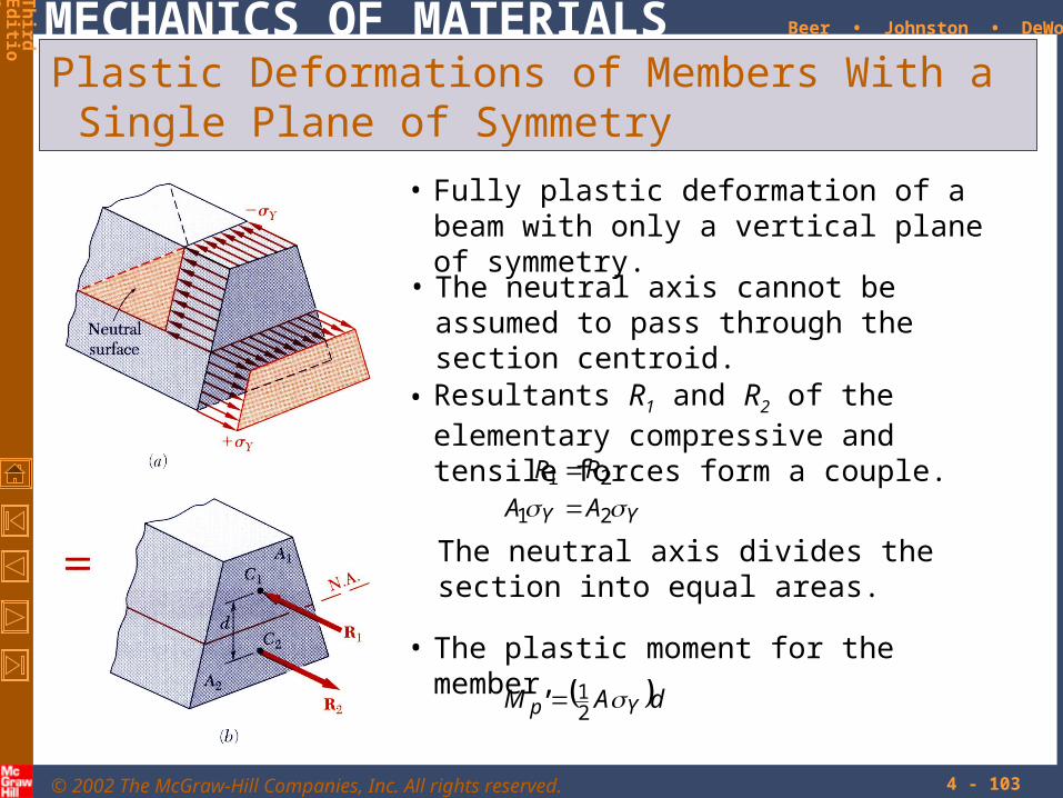
Plastic Deformations of Members With a Single Plane of Symmetry
• Fully plastic deformation of a beam with only a vertical plane of symmetry.
• Resultants R1 and R2 of the elementary compressive and tensile forces form a couple.
YY AA
RR
21
21
The neutral axis divides the section into equal areas.
• The plastic moment for the member,
dAM Yp 21
• The neutral axis cannot be assumed to pass through the section centroid.

© 2002 The McGraw-Hill Companies, Inc. All rights reserved.
MECHANICS OF MATERIALS
Th
irdE
ditio
n
Beer • Johnston • DeWolf
4 - 104
Residual Stresses
• Plastic zones develop in a member made of an elastoplastic material if the bending moment is large enough.
• Since the linear relation between normal stress and strain applies at all points during the unloading phase, it may be handled by assuming the member to be fully elastic.
• Residual stresses are obtained by applying the principle of superposition to combine the stresses due to loading with a moment M (elastoplastic deformation) and unloading with a moment -M (elastic deformation).
• The final value of stress at a point will not, in general, be zero.

© 2002 The McGraw-Hill Companies, Inc. All rights reserved.
MECHANICS OF MATERIALS
Th
irdE
ditio
n
Beer • Johnston • DeWolf
4 - 105
Example 4.05, 4.06
A member of uniform rectangular cross section is subjected to a bending moment M = 36.8 kN-m. The member is made of an elastoplastic material with a yield strength of 240 MPa and a modulus of elasticity of 200 GPa.
Determine (a) the thickness of the elastic core, (b) the radius of curvature of the neutral surface.
After the loading has been reduced back to zero, determine (c) the distribution of residual stresses, (d) radius of curvature.

© 2002 The McGraw-Hill Companies, Inc. All rights reserved.
MECHANICS OF MATERIALS
Th
irdE
ditio
n
Beer • Johnston • DeWolf
4 - 106
Example 4.05, 4.06
mkN 8.28
MPa240m10120
m10120
10601050
36
36
233322
32
YY c
IM
mmbcc
I
• Maximum elastic moment:
• Thickness of elastic core:
666.0mm60
1mkN28.8mkN8.36
1
2
2
31
23
2
2
31
23
YY
Y
YY
y
c
y
c
y
c
yMM
mm802 Yy
• Radius of curvature:
3
3
3
9
6
102.1
m1040
102.1
Pa10200
Pa10240
Y
Y
YY
YY
y
y
E
m3.33

© 2002 The McGraw-Hill Companies, Inc. All rights reserved.
MECHANICS OF MATERIALS
Th
irdE
ditio
n
Beer • Johnston • DeWolf
4 - 107
Example 4.05, 4.06
• M = 36.8 kN-m
MPa240
mm40
Y
Yy
• M = -36.8 kN-m
Y
36
2MPa7.306m10120
mkN8.36
I
Mcm
• M = 0
6
3
6
9
6
105.177
m1040
105.177
Pa10200
Pa105.35
core, elastic theof edge At the
x
Y
xx
y
E
m225

© 2002 The McGraw-Hill Companies, Inc. All rights reserved.
MECHANICS OF MATERIALS
Th
irdE
ditio
n
Beer • Johnston • DeWolf
4 - 108

© 2002 The McGraw-Hill Companies, Inc. All rights reserved.
MECHANICS OF MATERIALS
Th
irdE
ditio
n
Beer • Johnston • DeWolf
4 - 109
Unsymmetric Bending
• Analysis of pure bending has been limited to members subjected to bending couples acting in a plane of symmetry.
• Will now consider situations in which the bending couples do not act in a plane of symmetry.
• In general, the neutral axis of the section will not coincide with the axis of the couple.
• Cannot assume that the member will bend in the plane of the couples.
• The neutral axis of the cross section coincides with the axis of the couple
• Members remain symmetric and bend in the plane of symmetry.

© 2002 The McGraw-Hill Companies, Inc. All rights reserved.
MECHANICS OF MATERIALS
Th
irdE
ditio
n
Beer • Johnston • DeWolf
4 - 110
Unsymmetric Bending
Wish to determine the conditions under which the neutral axis of a cross section of arbitrary shape coincides with the axis of the couple as shown.
•
couple vector must be directed along a principal centroidal axis
inertiaofproductIdAyz
dAc
yzdAzM
yz
mxy
0or
0
• The resultant force and moment from the distribution of elementary forces in the section must satisfy
coupleappliedMMMF zyx 0
•
neutral axis passes through centroid
dAy
dAc
ydAF mxx
0or
0
•
defines stress distribution
inertiaofmomentIIc
Iσ
dAc
yyMM
zm
mz
Mor

© 2002 The McGraw-Hill Companies, Inc. All rights reserved.
MECHANICS OF MATERIALS
Th
irdE
ditio
n
Beer • Johnston • DeWolf
4 - 111
Unsymmetric BendingSuperposition is applied to determine stresses in the most general case of unsymmetric bending.
• Resolve the couple vector into components along the principle centroidal axes.
sincos MMMM yz
• Superpose the component stress distributions
y
y
z
zx I
yM
I
yM
• Along the neutral axis,
tantan
sincos0
y
z
yzy
y
z
zx
I
I
z
y
I
yM
I
yM
I
yM
I
yM

© 2002 The McGraw-Hill Companies, Inc. All rights reserved.
MECHANICS OF MATERIALS
Th
irdE
ditio
n
Beer • Johnston • DeWolf
4 - 112
Example 4.08
A 1600 lb-in couple is applied to a rectangular wooden beam in a plane forming an angle of 30 deg. with the vertical. Determine (a) the maximum stress in the beam, (b) the angle that the neutral axis forms with the horizontal plane.
SOLUTION:
• Resolve the couple vector into components along the principle centroidal axes and calculate the corresponding maximum stresses.
sincos MMMM yz
• Combine the stresses from the component stress distributions.
y
y
z
zx I
yM
I
yM
• Determine the angle of the neutral axis.
tantany
z
I
I
z
y

© 2002 The McGraw-Hill Companies, Inc. All rights reserved.
MECHANICS OF MATERIALS
Th
irdE
ditio
n
Beer • Johnston • DeWolf
4 - 113
Example 4.08• Resolve the couple vector into components and calculate
the corresponding maximum stresses.
psi5.609
in9844.0
in75.0inlb800
along occurs todue stress nsilelargest te The
psi6.452in359.5
in75.1inlb1386
along occurs todue stress nsilelargest te The
in9844.0in5.1in5.3
in359.5in5.3in5.1
inlb80030sininlb1600
inlb138630cosinlb1600
42
41
43121
43121
y
y
z
z
z
z
y
z
y
z
I
zM
ADM
I
yM
ABM
I
I
M
M
• The largest tensile stress due to the combined loading occurs at A.
5.6096.45221max psi1062max

© 2002 The McGraw-Hill Companies, Inc. All rights reserved.
MECHANICS OF MATERIALS
Th
irdE
ditio
n
Beer • Johnston • DeWolf
4 - 114
Example 4.08
• Determine the angle of the neutral axis.
143.3
30tanin9844.0
in359.5tantan
4
4
y
z
I
I
o4.72

© 2002 The McGraw-Hill Companies, Inc. All rights reserved.
MECHANICS OF MATERIALS
Th
irdE
ditio
n
Beer • Johnston • DeWolf
4 - 115
General Case of Eccentric Axial Loading
• Consider a straight member subject to equal and opposite eccentric forces.
• The eccentric force is equivalent to the system of a centric force and two couples.
PbMPaM
P
zy force centric
• By the principle of superposition, the combined stress distribution is
y
y
z
zx I
zM
I
yM
A
P
• If the neutral axis lies on the section, it may be found from
A
Pz
I
My
I
M
y
y
z
z