Embed Size (px)
Citation preview
PURCHASING DEPARTMENT 1772 County Services Parkway Marietta, Georgia 30008-4012 Mark Kohntopp (770) 528-8400/FAX (770) 528-1154 INTERIM DIRECTOR
ADDENDUM No. 4
Sealed Bid # 10-5520 Request for Proposal
HVAC System Improvements Project Cobb County Central Library
266 Roswell Street Marietta, Georgia 30060
DATE: September 2, 2010
Page 1 of 152 The following addendum hereby amends and/or modifies the Proposal Documents and specifications as originally issued for this project. All proposers are subject to the provisions of this Addendum.
Proposers shall acknowledge receipt of this addendum. Include this original form inside your proposal package.
This Addendum consists of:
Specifications omitted from the initial proposal
All bids must be received before 12:00 (noon) by the Bid Opening date. Bids shall be delivered to Cobb County Purchasing Department, 1772 County Services Parkway, Marietta, GA 30008. Electronic / faxed bid response will not be considered.
I acknowledge that I have received Addendum No. 4
Sealed Bid # 10-5520 Request for Proposal
HVAC System Improvements Project Cobb County Central Library
266 Roswell Street Marietta, Georgia 30060
____________________________________ Company Name ____ Signature Date Sent to Purchasing ______ Please Print Name
Please sign, date, and return this form ONLY to:
Cobb County Purchasing Department Fax #: 770-528-1154
E-Mail: [email protected]
Please note: The deadline for questions is: September 7, 2010 by 5:00 pm Any questions received after this deadline will not be considered.
Federal Energy Grant - HVAC Improvements - Cobb County Central Library 23 0513 Common Motor Requirements For HVAC Equipment
SECTION 23 0513
COMMON MOTOR REQUIREMENTS FOR HVAC EQUIPMENT
PART 1 GENERAL
1.01 SECTION INCLUDES
A. Single phase electric motors.
B. Three phase electric motors.
1.02 RELATED REQUIREMENTS
A. Section 26 2419 - Motor Control Centers.
B. Section 26 2717 - Equipment Wiring: Electrical characteristics and wiring connections.
C. Section 23-0514 – Adjustable Frequency Drives with Bypass.
1.03 REFERENCE STANDARDS
A. ABMA STD 9 - Load Ratings and Fatigue Life for Ball Bearings; American Bearing Manufacturers Association, Inc.; 1990 (Reapproved 2000).
B. IEEE 112 - IEEE Standard Test Procedure for Polyphase Induction Motors and Generators; Institute of Electrical and Electronic Engineers; 2004.
C. NEMA MG 1 - Motors and Generators; National Electrical Manufacturers Association; 2007.
D. NFPA 70 - National Electrical Code; National Fire Protection Association; 2008.
1.04 SUBMITTALS
A. See Section 01 3000 - Administrative Requirements, for submittal procedures.
B. Product Data: Provide wiring diagrams with electrical characteristics and connection requirements.
C. Test Reports: Indicate test results verifying nominal efficiency and power factor for three phase motors larger than 5 horsepower.
D. Manufacturer's Installation Instructions: Indicate setting, mechanical connections, lubrication, and wiring instructions.
E. Operation Data: Include instructions for safe operating procedures.
F. Maintenance Data: Include assembly drawings, bearing data including replacement sizes, and lubrication instructions.
1.05 QUALITY ASSURANCE
A. Manufacturer Qualifications: Company specializing in manufacture of electric motors for Commercial use, and their accessories, with minimum five years documented product development, testing, and manufacturing experience.
B. Conform to NFPA 70.
C. Provide certificate of compliance from authority having jurisdiction indicating approval of high efficiency motors.
D. Products Requiring Electrical Connection: Listed and classified by Underwriters Laboratories Inc. as suitable for the purpose specified and indicated.
1.06 DELIVERY, STORAGE, AND HANDLING
A. Protect motors stored on site from weather and moisture by maintaining factory covers and suitable weather-proof covering.
1.07 WARRANTY
A. See Section 01 7800 - Closeout Submittals, for additional warranty requirements.
B. Provide five year manufacturer warranty for motors larger than 20 horsepower.
Common Motor Requirements For HVAC Equipment 23 0513 - 1
Federal Energy Grant - HVAC Improvements - Cobb County Central Library 23 0513 Common Motor Requirements For HVAC Equipment PART 2 PRODUCTS
2.01 MANUFACTURERS
A. Lincoln Motors: www.lincolnmotors.com.
B. A. O. Smith Electrical Products Company: www.aosmithmotors.com.
C. Reliance Electric/Rockwell Automation: www.reliance.com.
D. Substitutions: See Section 01 6000 - Product Requirements.
2.02 GENERAL CONSTRUCTION AND REQUIREMENTS
A. Electrical Service: 480Y / 277V.
B. Electrical Service: 1. Motors 3/4 HP and Smaller: 115 volts, single phase, 60 Hz. 2. Motors Larger than 3/4 Horsepower: 480 volts, three phase, 60 Hz.
C. Nominal Efficiency: 1. Open Motor with Two Poles: 82.5. 2. Open Motor with Four Poles: 82.5. 3. Enclosed Motor with Two Poles: 75.5. 4. Enclosed Motor with Four Poles: 82.5.
D. Construction: 1. Open drip-proof type except where specifically noted otherwise. 2. Design for continuous operation in 40 degrees C environment. 3. Design for temperature rise in accordance with NEMA MG 1 limits for insulation class,
service factor, and motor enclosure type. 4. Motors with frame sizes 254T and larger: Energy Efficient Type.
E. Visible Nameplate: Indicating motor horsepower, voltage, phase, cycles, RPM, full load amps, locked rotor amps, frame size, manufacturer's name and model number, service factor, power factor, efficiency.
F. Wiring Terminations: 1. Provide terminal lugs to match branch circuit conductor quantities, sizes, and materials
indicated. Enclose terminal lugs in terminal box sized to NFPA 70, threaded for conduit. 2. For fractional horsepower motors where connection is made directly, provide threaded
conduit connection in end frame.
2.03 APPLICATIONS
A. Exception: Motors less than 250 watts, for intermittent service may be the equipment manufacturer's standard and need not conform to these specifications.
B. Single phase motors for fans: Capacitor start, capacitor run type.
C. Motors located in air cooled condensers: Totally enclosed type.
D. Motors located in in draw through cooling towers: Totally enclosed weatherproof epoxy-treated type.
2.04 SINGLE PHASE POWER - CAPACITOR START MOTORS
A. Starting Torque: Three times full load torque.
B. Starting Current: Less than five times full load current.
C. Pull-up Torque: Up to 350 percent of full load torque.
D. Breakdown Torque: Approximately 250 percent of full load torque.
E. Motors: Capacitor in series with starting winding; provide capacitor-start/capacitor-run motors with two capacitors in parallel with run capacitor remaining in circuit at operating speeds.
F. Drip-proof Enclosure: Class A (50 degrees C temperature rise) insulation, NEMA Service Factor, prelubricated ball bearings.
Common Motor Requirements For HVAC Equipment 23 0513 - 2

Federal Energy Grant - HVAC Improvements - Cobb County Central Library 23 0513 Common Motor Requirements For HVAC Equipment
G. Enclosed Motors: Class A (50 degrees C temperature rise) insulation, 1.0 Service Factor, prelubricated ball bearings.
2.05 THREE PHASE POWER - SQUIRREL CAGE MOTORS
A. Starting Torque: Between 1 and 1-1/2 times full load torque.
B. Starting Current: Six times full load current.
C. Power Output, Locked Rotor Torque, Breakdown or Pull Out Torque: NEMA Design B characteristics.
D. Design, Construction, Testing, and Performance: Conform to NEMA MG 1 for Design B motors.
E. Insulation System: NEMA Class F.
F. Testing Procedure: In accordance with IEEE 112. Load test motors to determine free from electrical or mechanical defects in compliance with performance data.
G. Motor Frames: NEMA Standard T-Frames of steel, aluminum, or cast iron with end brackets of cast iron or aluminum with steel inserts.
H. Bearings: Grease lubricated anti-friction ball bearings with housings equipped with plugged provision for relubrication, rated for minimum ABMA STD 9, L-10 life of 20,000 hours. Calculate bearing load with NEMA minimum V-belt pulley with belt center line at end of NEMA standard shaft extension. Stamp bearing sizes on nameplate.
I. Sound Power Levels: To NEMA MG 1.
J. Weatherproof Epoxy Sealed Motors: Epoxy seal windings using vacuum and pressure with rotor and starter surfaces protected with epoxy enamel; bearings double shielded with waterproof non-washing grease.
K. Nominal Efficiency: As scheduled at full load and rated voltage when tested in accordance with IEEE 112.
L. Nominal Power Factor: As scheduled at full load and rated voltage when tested in accordance with IEEE 112.
PART 3 EXECUTION
3.01 INSTALLATION
A. Install in accordance with manufacturer's instructions.
B. Install securely on firm foundation. Mount ball bearing motors with shaft in any position.
C. Check line voltage and phase and ensure agreement with nameplate.
3.02 SCHEDULE
A. Three Phase - Energy Efficient, Open Drip-Proof Performance: 1. 1800 rpm.
a. 2 hp: 1) NEMA Frame: 145T. 2) Minimum Percent Power Factor: 85. 3) Minimum Percent Efficiency: 84.
b. 10 hp: 1) NEMA Frame: 215T. 2) Minimum Percent Power Factor: 85. 3) Minimum Percent Efficiency: 89.
c. 15 hp: 1) NEMA Frame: 256T. 2) Minimum Percent Power Factor: 85. 3) Minimum Percent Efficiency: 91.
d. 25 hp: 1) NEMA Frame: 284T.
Common Motor Requirements For HVAC Equipment 23 0513 - 3

Federal Energy Grant - HVAC Improvements - Cobb County Central Library 23 0513 Common Motor Requirements For HVAC Equipment
Common Motor Requirements For HVAC Equipment 23 0513 - 4
2) Minimum Percent Power Factor: 85. 3) Minimum Percent Efficiency: 91.
e. 40 hp: 1) NEMA Frame: 324T. 2) Minimum Percent Power Factor: 83. 3) Minimum Percent Efficiency: 92.
B. Three Phase - Energy Efficient, Totally Enclosed, Fan Cooled Performance: 1. 1800 rpm.
a. 10 hp: 1) NEMA Frame: 215T. 2) Minimum Percent Power Factor: 84. 3) Minimum Percent Efficiency: 90.
TABLE OF MOTORS
MARK HP TYPE VOLTAGE FLA
P1 10 ODP 460 11.9
P2 20 ODP 460 24.2
P3 10 ODP 460 11.9
P4 2 ODP 460 2.8
AH1 15 ODP 460 18.5
AH2 40 ODP 460 46.0
AH4 25 ODP 460 29.2
CT1 10 TEFC 460 12.0
END OF SECTION
Federal Energy Grant - HVAC Improvements - Cobb County Central Library 23 0514 Adjustable Frequency Drives with Bypass
Adjustable Frequency Drives with Bypass 23 0514 - 1
SECTION 23 0514
ADJUSTABLE FREQUENCY DRIVES WITH BYPASS
PART 1 GENERAL
1.01 SCOPE
A. This specification describes the electrical, mechanical, environmental, agency and reliability requirements for three phase, adjustable frequency drives as specified herein and as shown on the contract drawings.
1.02 REFERENCES
A. The adjustable frequency drives and all components shall be designed, manufactured and tested in accordance with the latest applicable standards. 1. Institute of Electrical and Electronic Engineers (IEEE)
a. IEEE 519-1992: Guide for harmonic content and control. 2. Underwriters Laboratories (UL508C: Power Conversion Equipment)
a. UL b. Cul
3. National Electrical Manufacturer’s Association (NEMA) a. ICS 7.0: Industrial Controls & Systems for VSDs.
4. IEC 61800-2 and –3. EN 50082-1 and -2 a. Fulfill all EMC immunity requirements.
B. In case of conflict between the requirements of this section and those of the listed documents, the requirements of this section shall prevail.
1.03 SUBMITTALS
1.03.1 SUBMITTALS FOR REVIEW / APPROVAL
A. The following information shall be submitted to the Engineer. 1. Dimensioned outline drawing. 2. Control Schematic diagram. 3. Power and control connection diagram(s)
B. Submit four (4) copies of the above information.
1.03.2 SUBMITTALS FOR INFORMATION
A. When requested by the Engineer the following product information shall be submitted: 1. Product bulletins. 2. Technical product data sheets. 3. Harmonic analysis result.
1.03.3 SUBMITTALS FOR CLOSE-OUT
A. The following information shall be submitted for record purposes prior to final payment. 1. Final as-built drawings and information for items listed section in 1.04.1. 2. Installation information.
1.04 QUALIFICATIONS
A. The supplier of the assembly shall be the manufacturer of the electromechanical power components used within the assembly, such as bypass contactors, power distribution circuit breakers, when specified. These parts, when specified, shall have a commonality with other manufacturer’s products.
B. For the equipment specified herein, the manufacturer shall be ISO 9002 certified.
C. The supplier of this equipment shall have produced similar electrical equipment for a minimum period of ten (10) years. When requested by the Engineer, an acceptable list of installations with similar equipment shall be provided demonstrating compliance with this requirement.

Federal Energy Grant - HVAC Improvements - Cobb County Central Library 23 0514 Adjustable Frequency Drives with Bypass
Adjustable Frequency Drives with Bypass 23 0514 - 2
D. Adjustable Frequency Drives shall be on the basis of Johnson Controls VSD Series for function and quality. Approved Equal: ABB, Square D, Eaton Electrical.
1.05 DELIVERY, STORAGE, AND HANDLING
A. Equipment shall be handled and stored in accordance with manufacturer's instructions. One (1) copy of these instructions shall be included with the equipment at time of shipment.
1.06 OPERATION AND MAINTENANCE MANUALS
A. Five (5) copies of the equipment operation and maintenance manuals shall be provided.
B. Operation and maintenance manuals shall include the following information: 1. Instruction books. 2. Recommended renewal parts list. 3. Drawings and information required by section 1.04.3.
PART 2 PRODUCTS
2.01 ADJUSTABLE FREQUENCY DRIVES (VSD)
A. Where shown on the drawings, adjustable frequency drives 1 through 150 HP shall have the following features: 1. The VSDs shall be rated for 480 Vac (optional input voltages of 208 Vac through 60 HP, 240 Vac
through 75 HP). The VSD shall provide microprocessor based control for three-phase induction motors. The controller’s full load output current rating shall be based on variable torque application at 40 C ambient and 1-16 kHz switching frequency below 50 HP and 1-10 kHz 50 HP and above to reduce motor noise and avoid increased motor losses.
2. The VSDs shall be of the Pulse Width Modulated (PWM) design converting the utility input voltage and frequency to a variable voltage and frequency output via a two-step operation. Adjustable Current Source VSDs are not accepted. Insulated Gate Bipolar Transistors (IGBTs) shall be used in the inverter section. Bipolar Junction Transistors, GTOs or SCRs are not accepted. The VSD shall run at the above listed switching frequencies.
3. The VSDs shall have efficiency at full load and speed that exceeds 95% for VSDs below 15 HP and 97% for drives 15 HP and above. The efficiency shall exceed 90% at 50% speed and load.
4. The VSDs shall maintain a minimum line side displacement power factor of 0.96, regardless of speed and load.
5. The VSDs shall have a one (1) minute overload current rating of 110% for variable torque applications.
6. The VSDs shall be capable of operating any NEMA design B squirrel cage induction motor, regardless of manufacturer, with a horsepower and current rating within the capacity of the VSD.
7. The VSDs shall have an integral EMI/RFI filter as standard. 8. The VSDs shall limit harmonic distortion reflected onto the utility system to voltage and current
levels as defined by IEEE 519-1992 for general systems applications, by utilizing the standard 3% nominal impedance integral ac three-phase line reactor. DC link chokes are not accepted.
9. Any harmonic calculations shall be done based on the kVA capacity, X/R ratio and the impedance of the utility transformer feeding the installation, as noted on the drawings, and the total system load. The calculations shall be made with the point of common coupling (PCC) being the point where the utility feeds multiple customers.
10. Total harmonic distortion shall be calculated under worst case conditions in accordance with the procedure outlined in IEEE 519-1992. Copies of these calculations are to be made available upon request. The contractor shall provide any needed information to the VSD supplier three ( 3 ) weeks prior to requiring harmonic calculations.
11. The system containing the VSDs shall comply with the 5% level of total harmonic distortion of line voltage and the line current limits as defined in IEEE 519-1992. If the system cannot meet the harmonic levels with the VSDs provided with the standard input line reactor or optional input isolation transformer, the VSD manufacturer shall supply an eighteen pulse, multiple bridge rectifier ac to dc conversion section with phase shifting transformer for all drives above 75 HP. This eighteen pulse rectifier converter shall result in a multiple pulse current waveform that will more nearly approximate a true sinewave to reduce voltage harmonic content on the utility line.

Federal Energy Grant - HVAC Improvements - Cobb County Central Library 23 0514 Adjustable Frequency Drives with Bypass
Adjustable Frequency Drives with Bypass 23 0514 - 3
The phase shifting transformer shall be of a single winding type to optimize its KVA rating and harmonic cancellation capability.
Harmonic filters are not accepted above 75 HP. 12. The VSDs shall be able to start into a spinning motor. The VSDs shall be able to determine the
motor speed in any direction and resume operation without tripping. If the motor is spinning in the reverse direction, the VSDs shall start into the motor in the reverse direction, bring the motor to a controlled stop, and then accelerate the motor to the preset speed.
Standard operating conditions shall be: a. Incoming Power: Three-phase, 208 / 240 / 480 (+10% to -15%) and 50/60 Hz (+/-5 Hz) power
to a fixed potential DC bus level. b. Frequency stability of +/-0.05% for 24 hours with voltage regulation of +/-1% of maximum
rated output voltage. c. Speed regulation of +/- 0.5% of base speed. d. Load inertia dependant carryover ( ridethrough ) during utility loss. e. Insensitive to input line rotation. f. Humidity: 0 to 95% (non-condensing and non-corrosive). g. Altitude: 0 to 3,300 feet (1000 meters) above sea level. h. Ambient Temperature: -10 to 40 C (VT). i. Storage Temperature: -40 to 70 C.
13. Control Functions a. Frequently accessed VSD programmable parameters shall be adjustable from a digital
operator keypad located on the front of the VSD. The VSDs shall have a 3 line alphanumeric programmable display with status indicators. Keypads must use plain English words for parameters, status, and diagnostic messages. Keypads that are difficult to read or understand are not accepted, and particularly those that use alphanumeric code and tables. Keypads shall be adjustable for contrast with large characters easily visible in normal ambient light.
b. The keypad shall include a Hand-Off-Auto membrane selection and an Inverter/Bypass membrane selection. When in “Hand” the VSD will be started and the speed will be controlled from the up/down arrows. When in “Off”, the VSD will be stopped. In “Auto”, the VSD will start via an external contact closure or a communication network and the VSD speed will be controlled via an external speed reference.
c. The keypad shall have copy / paste capability. d. Upon initial power up of the VSD, the keypad shall display a start up guide that will sequence
all the necessary parameter adjustments for general start up. e. Standard advanced programming and trouble-shooting functions shall be available by using a
personal computer’s RS-232 port and Windows™ based software. In addition the software shall permit control and monitoring via the VSD’s RS232 port. The manufacturer shall supply a diskette with the required software. An easily understood instruction manual and software help screens shall also be provided. The computer software shall be used for modifying the drive setup and reviewing diagnostic and trend information as outlined in this section through section 18.
f. The operator shall be able to scroll through the keypad menu to choose between the following: 1) Parameter Menu 2) Keypad Control 3) System Menu 4) Expander Boards 5) Monitoring Menu 6) Operate Menu
g. The following setups and adjustments, at a minimum, are to be available: 1) Start command from keypad, remote or communications port.

Federal Energy Grant - HVAC Improvements - Cobb County Central Library 23 0514 Adjustable Frequency Drives with Bypass
Adjustable Frequency Drives with Bypass 23 0514 - 4
2) Speed command from keypad, remote or communications port. 3) Motor direction selection. 4) Maximum and minimum speed limits. 5) Acceleration and deceleration times, two settable ranges. 6) Critical (skip) frequency avoidance. 7) Torque limit. 8) Multiple attempt restart function. 9) Multiple preset speeds adjustment. 10) Catch a spinning motor start or normal start selection. 11) Programmable analog output.
14. The VSD shall have the following system interfaces: a. Inputs – A minimum of six (6) programmable digital inputs, two (2) analog inputs and serial
communications interface shall be provided with the following available as a minimum: 1) Remote manual/auto. 2) Remote start/stop. 3) Remote forward/reverse. 4) Remote preset speeds. 5) Remote external trip. 6) Remote fault reset. 7) Process control speed reference interface, 4-20mAdc. 8) Potentiometer or process control speed reference interface, 0 -10Vdc. 9) RS232 programming and operation interface port.
b. Outputs – A minimum of two (2) discrete programmable digital outputs, one (1) programmable open collector output, and one (1) programmable analog output shall be provided, with the following available at minimum. 1) Programmable relay outputs with one (1) set of Form C contacts for each, selectable
with the following available at minimum. a) Fault b) Run c) Ready d) Reversing e) Jogging f) At speed g) In torque limit h) Motor rotation direction opposite of commanded i) Overtemperature
2) Programmable open collector output with available 24Vdc power supply and selectable with the following available at minimum: a) Fault b) Run c) Ready d) Reversing e) Jogging f) At speed g) In torque limit h) Motor rotation direction opposite of commanded i) Overtemperature
3) Programmable analog output signal, selectable with the following available at minimum: a) Output frequency b) Frequency reference c) Motor speed d) Output current e) Motor torque f) Motor power

Federal Energy Grant - HVAC Improvements - Cobb County Central Library 23 0514 Adjustable Frequency Drives with Bypass
Adjustable Frequency Drives with Bypass 23 0514 - 5
g) Motor voltage h) DC link voltage i) PID controller reference value j) PID controller actual value 1 k) PID controller actual value 2 l) PID controller error value m) PID controller output
c. Capability of two additional expandable I/O interface cards. Upon installation, software shall automatically identify the interface card and activate the appropriate parameters.
15. Monitoring and Displays a. The VSD’s display shall be a LCD type capable of displaying three (3) lines of text and the
following thirteen (13) status indicators: 1) Run 2) Forward 3) Reverse 4) Stop 5) Ready 6) Alarm 7) Fault 8) I/O Terminal 9) Keypad 10) Bus/comm. 11) Hand 12) Auto 13) Off
b. The VSD’s keypad shall be capable of displaying the following monitoring functions at a minimum: 1) Motor Speed (RPM and %) 2) Frequency reference 3) Output frequency 4) Motor current 5) Motor torque 6) Motor power 7) Motor voltage 8) DC-link voltage 9) Heatsink temperature 10) Motor run time (resetable) 11) Total operating days counter 12) Operating hours (resetable) 13) Total megawatt hours 14) Megawatt hours (resetable) 15) Voltage level of analog input 16) Current level of analog input 17) Digital inputs status 18) Digital and relay outputs status 19) Motor temperature rise 20) PID references
16. Protective Functions a. The VSD shall include the following protective features at minimum:
1) Overcurrent 2) Overvoltage 3) System fault 4) Undervoltage 5) Input line supervision 6) Output phase supervision 7) Undertemperature
Federal Energy Grant - HVAC Improvements - Cobb County Central Library 23 0514 Adjustable Frequency Drives with Bypass
Adjustable Frequency Drives with Bypass 23 0514 - 6
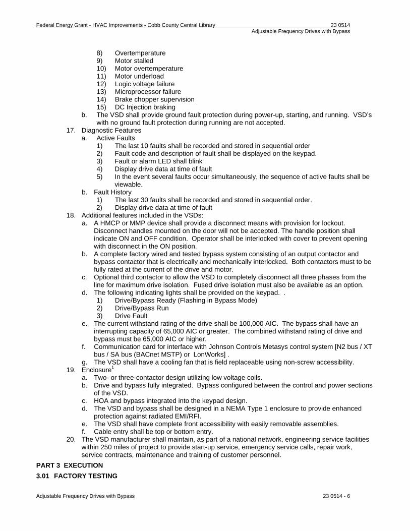
8) Overtemperature 9) Motor stalled 10) Motor overtemperature 11) Motor underload 12) Logic voltage failure 13) Microprocessor failure 14) Brake chopper supervision 15) DC Injection braking
b. The VSD shall provide ground fault protection during power-up, starting, and running. VSD’s with no ground fault protection during running are not accepted.
17. Diagnostic Features a. Active Faults
1) The last 10 faults shall be recorded and stored in sequential order 2) Fault code and description of fault shall be displayed on the keypad. 3) Fault or alarm LED shall blink 4) Display drive data at time of fault 5) In the event several faults occur simultaneously, the sequence of active faults shall be
viewable. b. Fault History
1) The last 30 faults shall be recorded and stored in sequential order. 2) Display drive data at time of fault
18. Additional features included in the VSDs: a. A HMCP or MMP device shall provide a disconnect means with provision for lockout.
Disconnect handles mounted on the door will not be accepted. The handle position shall indicate ON and OFF condition. Operator shall be interlocked with cover to prevent opening with disconnect in the ON position.
b. A complete factory wired and tested bypass system consisting of an output contactor and bypass contactor that is electrically and mechanically interlocked. Both contactors must to be fully rated at the current of the drive and motor.
c. Optional third contactor to allow the VSD to completely disconnect all three phases from the line for maximum drive isolation. Fused drive isolation must also be available as an option.
d. The following indicating lights shall be provided on the keypad. . 1) Drive/Bypass Ready (Flashing in Bypass Mode) 2) Drive/Bypass Run 3) Drive Fault
e. The current withstand rating of the drive shall be 100,000 AIC. The bypass shall have an interrupting capacity of 65,000 AIC or greater. The combined withstand rating of drive and bypass must be 65,000 AIC or higher.
f. Communication card for interface with Johnson Controls Metasys control system [N2 bus / XT bus / SA bus (BACnet MSTP) or LonWorks] .
g. The VSD shall have a cooling fan that is field replaceable using non-screw accessibility. 19. Enclosure1
a. Two- or three-contactor design utilizing low voltage coils. b. Drive and bypass fully integrated. Bypass configured between the control and power sections
of the VSD. c. HOA and bypass integrated into the keypad design. d. The VSD and bypass shall be designed in a NEMA Type 1 enclosure to provide enhanced
protection against radiated EMI/RFI. e. The VSD shall have complete front accessibility with easily removable assemblies. f. Cable entry shall be top or bottom entry.
20. The VSD manufacturer shall maintain, as part of a national network, engineering service facilities within 250 miles of project to provide start-up service, emergency service calls, repair work, service contracts, maintenance and training of customer personnel.
PART 3 EXECUTION
3.01 FACTORY TESTING

Federal Energy Grant - HVAC Improvements - Cobb County Central Library 23 0514 Adjustable Frequency Drives with Bypass
Adjustable Frequency Drives with Bypass 23 0514 - 7
A. The following standard factory tests shall be performed on the equipment provided under this section. All tests shall be in accordance with the latest version of UL and NEMA standards. 1. All printed circuit boards shall be functionally tested via automatic test equipment prior to unit
installation. 2. All final assemblies shall be tested at full load with application of line-to-line and line-to-ground
bolted faults. The Adjustable Frequency Drive shall trip electronically without device failure. 3. After all tests have been performed; each VSD shall undergo a burn-in test. The drive shall be
burned in at 100% inductive or motor load without an unscheduled shutdown. 4. After the burn-in cycle is complete, each VSD shall be put through a motor load test before
inspection and shipping. B. The manufacturer shall provide three (3) certified copies of factory test reports.
C. All testing and manufacturing procedures shall be ISO 9002 certified.
3.02 FIELD QUALITY CONTROL A. Provide the services of a qualified manufacturer's employed Field Service Engineer or authorized
service representative to assist the Contractor in installation and start-up of the equipment specified under this section. The manufacturer's service representative shall provide technical direction and assistance to the Contractor in general assembly of the equipment, installation as specified in manufacturer’s installation instructions, wiring, application dependant adjustments, and verification of proper VSD operation.
B. The following minimum work shall be performed by the Contractor under the technical direction of the manufacturer's service representative. 1. Inspection and final adjustments. 2. Operational and functional checks of VSDs and spare parts. 3. The contractor shall certify that he has read the drive manufacturer’s installation instructions and
has installed the VSD in accordance with those instructions. C. The Contractor shall provide three (3) copies of the manufacturer's field start-up report before final
payment is made.
3.03 MAINTENANCE / WARRANTY SERVICE A. Standard warranty is twenty-four (24) months from the date of shipment and covers the factory repair or
replacement of the defective unit. B. Warranty is thirty-six (36) months from date of shipment when an authorized service representative
performs start up and includes parts.
3.04 FIELD TESTING A. Optional field testing
1. The VSD manufacturer shall perform harmonic measurements at the point where the utility feeds multiple customers (PCC) to verify compliance with IEEE 519-1992. A report of the voltage THD and current TDD shall be sent to the engineer. The contractor shall provide labor, material, and protection as needed to access the test points. The readings shall be taken with all drives and all other loads at full load, or as close as field conditions allow.
3.05 TRAINING A. The Contractor shall provide a training session for up to 5 owner's representatives for 8 Hours with a
maximum of One trip at a job site location determined by the owner. Training and instruction time shall be in addition to that required for start-up service.
B. The training shall be conducted by the manufacturer's qualified representative. C. The training program shall consist of the following:
1. Instructions on the proper operation of the equipment. 2. Instructions on the proper maintenance of the equipment.
END OF SECTION

Federal Energy Grant - HVAC Improvements - Cobb County Central Library 23 0516 Expansion Fittings And Loops For HVAC Piping
SECTION 23 0516
EXPANSION FITTINGS AND LOOPS FOR HVAC PIPING
PART 1 GENERAL
1.01 SECTION INCLUDES
A. Flexible pipe connectors.
1.02 RELATED REQUIREMENTS
A. Section 23 2113 - Hydronic Piping.
1.03 REFERENCE STANDARDS
A. ASTM A 269 - Standard Specification for Seamless and Welded Austenitic Stainless Steel Tubing for General Service; 2008.
1.04 SUBMITTALS
A. See Section 01 3000 - Administrative Requirements, for submittal procedures.
B. Product Data: 1. Flexible Pipe Connectors: Indicate maximum temperature and pressure rating, face-to-
face length, live length, hose wall thickness, hose convolutions per foot (meter) and per assembly, fundamental frequency of assembly, braid structure, and total number of wires in braid.
C. Design Data: Indicate selection calculations.
D. Manufacturer's Instructions: Indicate manufacturer's installation instructions, special procedures, and external controls.
E. Project Record Documents: Record installed locations of flexible pipe connectors, expansion joints, anchors, and guides.
F. Maintenance Data: Include adjustment instructions.
G. Maintenance Materials: Furnish the following for Owner's use in maintenance of project. 1. See Section 01 6000 - Product Requirements, for additional provisions.
1.05 REGULATORY REQUIREMENTS
A. Conform to UL requirements.
PART 2 PRODUCTS
2.01 FLEXIBLE PIPE CONNECTORS - STEEL PIPING
A. Manufacturers: 1. Mercer Rubber Company: www.mercer-rubber.com. 2. Metraflex Company: www.metraflex.com. 3. Substitutions: See Section 01 6000 - Product Requirements.
B. Inner Hose: Stainless Steel.
C. Exterior Sleeve: Double braided,.
D. Exterior Sleeve: None.
E. Pressure Rating: 200 psi and 250 degrees F (1380 kPa and 121 degrees C).
F. Joint: To match equipment connections.
G. Size: Use pipe sized units.
H. Maximum offset: 3/4 inch (20 mm) on each side of installed center line.
PART 3 EXECUTION
3.01 INSTALLATION
A. Install in accordance with manufacturer's instructions.
Expansion Fittings And Loops For HVAC Piping 23 0516 - 1
Federal Energy Grant - HVAC Improvements - Cobb County Central Library 23 0516 Expansion Fittings And Loops For HVAC Piping
Expansion Fittings And Loops For HVAC Piping 23 0516 - 2
B. Install flexible pipe connectors on pipes connected to vibration isolated equipment. Provide line size flexible connectors.
C. Install flexible connectors at right angles to displacement. Install one end immediately adjacent to isolated equipment and anchor other end. Install in horizontal plane unless indicated otherwise.
END OF SECTION

Federal Energy Grant - HVAC Improvements - Cobb County Central Library 23 0519 Meters And Gages For HVAC Piping
SECTION 23 0519
METERS AND GAGES FOR HVAC PIPING
PART 1 GENERAL
1.01 SECTION INCLUDES
A. Flow meters.
B. Pressure gages and pressure gage taps.
C. Thermometers and thermometer wells.
1.02 RELATED REQUIREMENTS
A. Section 23 2113 - Hydronic Piping.
B. Section 23 0923 - Direct-Digital Control System for HVAC.
C. Section 23 0993 - Sequence of Operations for HVAC Controls.
1.03 REFERENCE STANDARDS
A. ASME B40.100 - Pressure Gauges and Gauge Attachments; The American Society of Mechanical Engineers; 2005.
B. ASME MFC-3M - Measurement of Fluid Flow in Pipes Using Orifice, Nozzle and Venturi; The American Society of Mechanical Engineers; 2004.
C. ASTM E 1 - Standard Specification for ASTM Thermometers; 2007.
D. ASTM E 77 - Standard Test Method for Inspection and Verification of Thermometers; 2007.
1.04 SUBMITTALS
A. See Section 01 3000 - Administrative Requirements, for submittal procedures.
B. Product Data: Provide list that indicates use, operating range, total range and location for manufactured components.
C. Project Record Documents: Record actual locations of components and instrumentation.
D. Operation and Maintenance Data.
E. Maintenance Materials: Furnish the following for Owner's use in maintenance of project. 1. See Section 01 6000 - Product Requirements. for additional provisions. 2. Extra Gage Oil for Inclined Manometers: One bottle. 3. Extra Pressure Gages: Two of each type and size.
1.05 FIELD CONDITIONS
A. Do not install instrumentation when areas are under construction, except for required rough-in, taps, supports and test plugs.
PART 2 PRODUCTS
2.01 LIQUID FLOW METERS
A. Manufacturers: 1. Dwyer Instruments, Inc: www.dwyer-inst.com. 2. Venture Measurement Company: www.venturemeasurement.com. 3. McCrometer: www.mccrometer.com. 4. Substitutions: See Section 01 6000 - Product Requirements.
B. ASME MFC-3M Calibrated venturi orifice plate and flanges with valved taps, chart for conversion of differential pressure readings to flow rate, with pressure gage in case.
C. Annular element flow stations with meter set. 1. Measuring Station: Type 316 stainless steel pitot type flow element inserted through
welded threaded couplet; or installed in threaded nipple pipe section, with safety shut-off
Meters And Gages For HVAC Piping 23 0519 - 1

Federal Energy Grant - HVAC Improvements - Cobb County Central Library 23 0519 Meters And Gages For HVAC Piping
valves and quick coupling connections, and permanent metal tag indicating design flow rate, reading for design flow rate, metered fluid, line size, station or location number. a. Pressure rating: 275 psi (1896 kPa). b. Maximum temperature: 400 degrees F (204 degrees C). c. Accuracy: Plus 0.55 percent to minus 2.30 percent.
2. Portable Meter Set: Dry single diaphragm type pressure gage with 6 inch (150 mm) dial pointer, stainless steel wetted metal parts, variable pulsation damper, equalizing valve, two bleed valves, and master chart for direct conversion of meter readings to flow rate, mounted in rust-proof carrying case with two ten foot (3 m) long rubber test hoses with brass valves or quick connections for measuring stations.
2.02 PRESSURE GAGES
A. Manufacturers: 1. Dwyer Instruments, Inc: www.dwyer-inst.com. 2. Moeller Instrument Co., Inc: www.moellerinstrument.com. 3. Omega Engineering, Inc: www.omega.com. 4. Substitutions: See Section 01 6000 - Product Requirements.
B. Pressure Gages: ASME B40.100, UL 393 drawn steel case, phosphor bronze bourdon tube, rotary brass movement, brass socket, with front recalibration adjustment, black scale on white background. 1. Case: Steel with brass bourdon tube. 2. Size: 3-1/2 inch (90 mm) diameter. 3. Mid-Scale Accuracy: One percent. 4. Scale: Psi.
2.03 PRESSURE GAGE TAPPINGS
A. Gage Cock: Tee or lever handle, brass for maximum 150 psi (1034 kPa).
B. Needle Valve: Brass, 1/4 inch (6 mm) NPT for minimum 150 psi (1034 kPa).
C. Pulsation Damper: Pressure snubber, brass with 1/4 inch (6 mm) connections.
D. Syphon: Steel, Schedule 40, 1/4 inch (6 mm) angle or straight pattern.
2.04 STEM TYPE THERMOMETERS
A. Manufacturers: 1. Dwyer Instruments, Inc: www.dwyer-inst.com. 2. Omega Engineering, Inc: www.omega.com. 3. Weksler Glass Thermometer Corp: www.wekslerglass.com. 4. Substitutions: See Section 01 6000 - Product Requirements.
B. Thermometers - Fixed Mounting: Red- or blue-appearing non-toxic liquid in glass; ASTM E 1; lens front tube, cast aluminum case with enamel finish. 1. Size: 7 inch (175 mm) scale. 2. Window: Clear Lexan. 3. Stem: 3/4 inch brass. 4. Accuracy: 2 percent, per ASTM E 77. 5. Calibration: Degrees F.
C. Thermometers - Adjustable Angle: Red- or blue-appearing non-toxic liquid in glass; ASTM E 1; lens front tube, cast aluminum case with enamel finish, cast aluminum adjustable joint with positive locking device; adjustable 360 degrees in horizontal plane, 180 degrees in vertical plane. 1. Size: 7 inch (175 mm) scale. 2. Window: Clear Lexan. 3. Stem: 3/4 inch (20 mm) NPT brass. 4. Accuracy: 2 percent, per ASTM E 77. 5. Calibration: Degrees F.
Meters And Gages For HVAC Piping 23 0519 - 2
Federal Energy Grant - HVAC Improvements - Cobb County Central Library 23 0519 Meters And Gages For HVAC Piping
Meters And Gages For HVAC Piping 23 0519 - 3
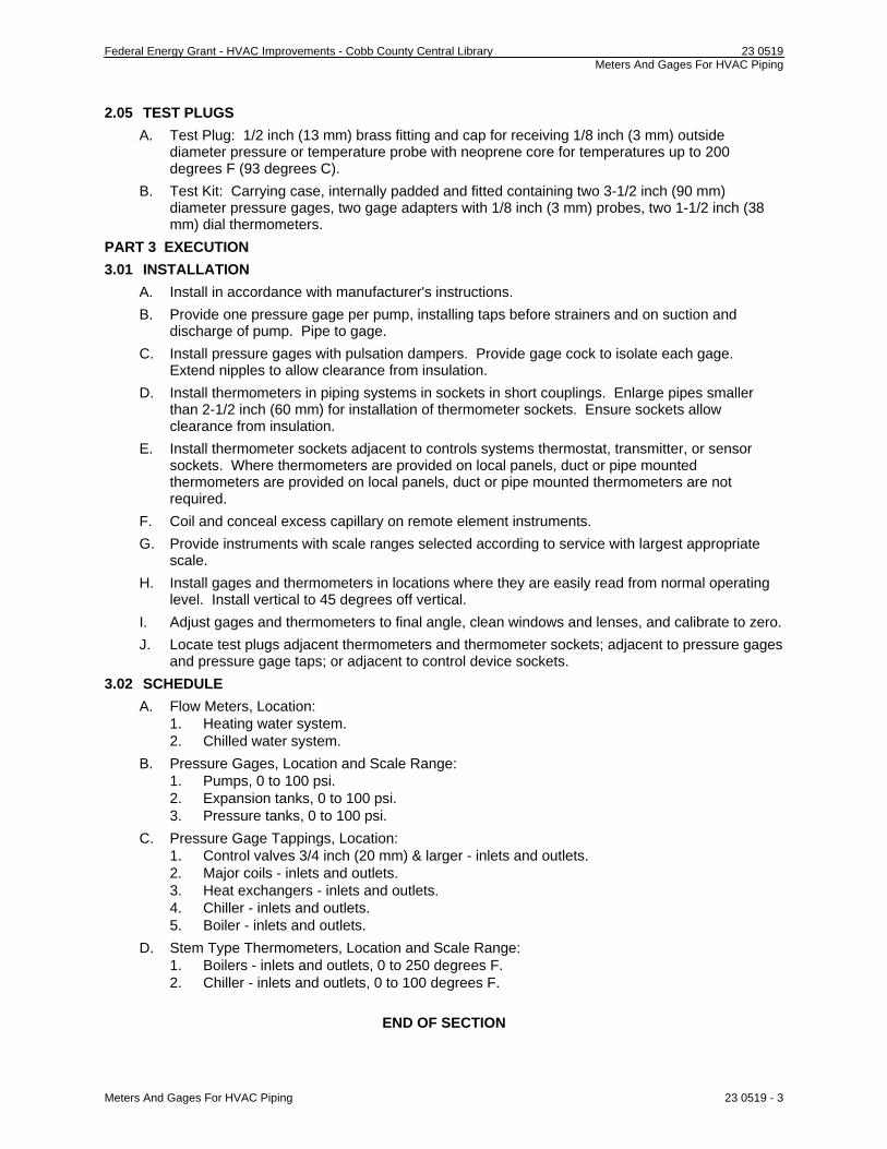
2.05 TEST PLUGS
A. Test Plug: 1/2 inch (13 mm) brass fitting and cap for receiving 1/8 inch (3 mm) outside diameter pressure or temperature probe with neoprene core for temperatures up to 200 degrees F (93 degrees C).
B. Test Kit: Carrying case, internally padded and fitted containing two 3-1/2 inch (90 mm) diameter pressure gages, two gage adapters with 1/8 inch (3 mm) probes, two 1-1/2 inch (38 mm) dial thermometers.
PART 3 EXECUTION
3.01 INSTALLATION
A. Install in accordance with manufacturer's instructions.
B. Provide one pressure gage per pump, installing taps before strainers and on suction and discharge of pump. Pipe to gage.
C. Install pressure gages with pulsation dampers. Provide gage cock to isolate each gage. Extend nipples to allow clearance from insulation.
D. Install thermometers in piping systems in sockets in short couplings. Enlarge pipes smaller than 2-1/2 inch (60 mm) for installation of thermometer sockets. Ensure sockets allow clearance from insulation.
E. Install thermometer sockets adjacent to controls systems thermostat, transmitter, or sensor sockets. Where thermometers are provided on local panels, duct or pipe mounted thermometers are provided on local panels, duct or pipe mounted thermometers are not required.
F. Coil and conceal excess capillary on remote element instruments.
G. Provide instruments with scale ranges selected according to service with largest appropriate scale.
H. Install gages and thermometers in locations where they are easily read from normal operating level. Install vertical to 45 degrees off vertical.
I. Adjust gages and thermometers to final angle, clean windows and lenses, and calibrate to zero.
J. Locate test plugs adjacent thermometers and thermometer sockets; adjacent to pressure gages and pressure gage taps; or adjacent to control device sockets.
3.02 SCHEDULE
A. Flow Meters, Location: 1. Heating water system. 2. Chilled water system.
B. Pressure Gages, Location and Scale Range: 1. Pumps, 0 to 100 psi. 2. Expansion tanks, 0 to 100 psi. 3. Pressure tanks, 0 to 100 psi.
C. Pressure Gage Tappings, Location: 1. Control valves 3/4 inch (20 mm) & larger - inlets and outlets. 2. Major coils - inlets and outlets. 3. Heat exchangers - inlets and outlets. 4. Chiller - inlets and outlets. 5. Boiler - inlets and outlets.
D. Stem Type Thermometers, Location and Scale Range: 1. Boilers - inlets and outlets, 0 to 250 degrees F. 2. Chiller - inlets and outlets, 0 to 100 degrees F.
END OF SECTION
Federal Energy Grant - HVAC Improvements - Cobb County Central Library 23 0548 Vibration And Seismic Controls For HVAC Piping And Equipment
SECTION 23 0548
VIBRATION AND SEISMIC CONTROLS FOR HVAC PIPING AND EQUIPMENT
PART 1 GENERAL
1.01 SECTION INCLUDES
A. Inertia bases.
B. Vibration isolators.
1.02 RELATED REQUIREMENTS
A. Section 03 3000 - Cast-in-Place Concrete.
1.03 SUBMITTALS
A. See Section 01 3000 - Administrative Requirements, for submittal procedures.
B. Product Data: Provide schedule of vibration isolator type with location and load on each.
C. Shop Drawings: Indicate inertia bases and locate vibration isolators, with static and dynamic load on each. Indicate seismic control measures.
D. Manufacturer's Instructions: Indicate installation instructions with special procedures and setting dimensions.
PART 2 PRODUCTS
2.01 MANUFACTURERS
A. Isolation Technology, Inc: www.isolationtech.com.
B. Kinetics Noise Control, Inc: www.kineticsnoise.com.
C. Mason Industries: www.mason-ind.com.
D. Substitutions: See Section 01 6000 - Product Requirements.
2.02 INERTIA BASES
A. Structural Bases: 1. Construction: Welded structural steel with gusseted brackets, to support equipment and
motor, with motor slide rails. 2. Design: Sufficiently rigid to prevent misalignment or undue stress on machine, and to
transmit design loads to isolators and snubbers.
B. Concrete Inertia Bases: 1. Construction: Structural steel channel perimeter frame, with gusseted brackets and
anchor bolts, reinforcing; concrete filled. 2. Mass: Minimum of 1.5 times weight of isolated equipment. 3. Connecting Point: Reinforced to connect isolators and snubbers to base. 4. Concrete: Minimum 3000 psi (20 mPa) concrete.
2.03 VIBRATION ISOLATORS
A. Open Spring Isolators: 1. Springs: Minimum horizontal stiffness equal to 75 percent vertical stiffness, with working
deflection between 0.3 and 0.6 of maximum deflection. Color code springs for load carrying capacity.
2. Spring Mounts: Provide with leveling devices, minimum 0.25 inch (6 mm) thick neoprene sound pads, and zinc chromate plated hardware.
3. Sound Pads: Size for minimum deflection of 0.05 inch (1.2 mm); meet requirements for neoprene pad isolators.
4. For Exterior and Humid Areas: Hot dipped galvanized housings and neoprene coated springs.
B. Restrained Open Spring Isolators:
Vibration And Seismic Controls For HVAC Piping And Equipment 23 0548 - 1

Federal Energy Grant - HVAC Improvements - Cobb County Central Library 23 0548 Vibration And Seismic Controls For HVAC Piping And Equipment
1. Springs: Minimum horizontal stiffness equal to 75 percent vertical stiffness, with working deflection between 0.3 and 0.6 of maximum deflection. Color code springs for load carrying capacity.
2. Spring Mounts: Provide with leveling devices, minimum 0.25 inch (6 mm) thick neoprene sound pads, and zinc chromate plated hardware.
3. Sound Pads: Size for minimum deflection of 0.05 inch (1.2 mm); meet requirements for neoprene pad isolators.
4. Restraint: Provide heavy mounting frame and limit stops.
C. Closed Spring Isolators: 1. Type : Closed spring mount with top and bottom housing separated with neoprene rubber
stabilizers. 2. Springs: Minimum horizontal stiffness equal to 75 percent vertical stiffness, with working
deflection between 0.3 and 0.6 of maximum deflection. Color code springs for load carrying capacity.
3. Housings: Incorporate neoprene isolation pad meeting requirements for neoprene pad isolators, and neoprene side stabilizers with minimum 0.25 inch (7 mm) clearance.
D. Restrained Closed Spring Isolators: 1. Type : Closed spring mount with top and bottom housing separated with neoprene rubber
stabilizers. 2. Springs: Minimum horizontal stiffness equal to 75 percent vertical stiffness, with working
deflection between 0.3 and 0.6 of maximum deflection. Color code springs for load carrying capacity.
3. Housings: Incorporate neoprene isolation pad meeting requirements for neoprene pad isolators, and neoprene side stabilizers with minimum 0.25 inch (7 mm) clearance and limit stops.
E. Spring Hangers: 1. Springs: Minimum horizontal stiffness equal to 75 percent vertical stiffness, with working
deflection between 0.3 and 0.6 of maximum deflection. Color code springs for load carrying capacity.
2. Housings: Incorporate neoprene isolation pad meeting requirements for neoprene pad isolators, or rubber hanger with threaded insert.
3. Misalignment: Capable of 20 degree hanger rod misalignment. 4. For Exterior and Humid Areas: Hot dipped galvanized housings and neoprene coated
springs.
F. Neoprene Pad Isolators: 1. Rubber or neoprene waffle pads.
a. Hardness: 30 durometer. b. Thickness: Minimum 1/2 inch (13 mm). c. Maximum Loading: 50 psi (345 kPa). d. Rib Height: Maximum 0.7 times width.
2. Configuration: Single layer. 3. Configuration: 1/2 inch (13 mm) thick waffle pads bonded each side of 1/4 inch (6 mm)
thick steel plate.
G. Rubber Mount or Hanger: Molded rubber designed for 0.4 inch (10 mm) deflection with threaded insert.
H. Glass Fiber Pads: Neoprene jacketed pre-compressed molded glass fiber.
I. Roof Mounting Curb: 14 inches (350 mm) high with rigid steel lower section containing adjustable spring pockets with restrained spring isolators, steel upper section to support rooftop equipment, and continuous elastomeric membrane extending from upper section for counterflashing over roofing.
PART 3 EXECUTION
3.01 INSTALLATION
Vibration And Seismic Controls For HVAC Piping And Equipment 23 0548 - 2

Federal Energy Grant - HVAC Improvements - Cobb County Central Library 23 0548 Vibration And Seismic Controls For HVAC Piping And Equipment
Vibration And Seismic Controls For HVAC Piping And Equipment 23 0548 - 3
A. Install in accordance with manufacturer's instructions.
B. Bases: 1. Set steel bases for one inch (25 mm) clearance between housekeeping pad and base. 2. Set concrete inertia bases for 2 inches (50 mm) clearance between housekeeping pad
and base. 3. Adjust equipment level.
C. On closed spring isolators, adjust so side stabilizers are clear under normal operating conditions.
D. Prior to making piping connections to equipment with operating weights substantially different from installed weights, block up equipment with temporary shims to final height. When full load is applied, adjust isolators to load to allow shim removal.
E. Support piping connections to equipment mounted on isolators using isolators or resilient hangers as follows: 1. Up to 4 Inches (100 mm) Pipe Size: First three points of support. 2. 5 to 8 Inches (125 to 200 mm) Pipe Size: First four points of support. 3. Select three hangers closest to vibration source for minimum 1.0 inch (25 mm) static
deflection or static deflection of isolated equipment. Select remaining isolators for minimum 1.0 inch (25 mm) static deflection or 1/2 static deflection of isolated equipment.
3.02 FIELD QUALITY CONTROL
A. Inspect isolated equipment after installation and submit report. Include static deflections.
END OF SECTION

Federal Energy Grant - HVAC Improvements - Cobb County Central Library 23 0553 Identification For HVAC Piping And Equipment
SECTION 23 0553
IDENTIFICATION FOR HVAC PIPING AND EQUIPMENT
PART 1 GENERAL
1.01 SECTION INCLUDES
A. Nameplates.
B. Tags.
C. Stencils.
D. Pipe Markers.
1.02 RELATED REQUIREMENTS
A. Section 09 9000 - Paints & Stains: Identification painting.
1.03 REFERENCE STANDARDS
A. ASME A13.1 - Scheme for the Identification of Piping Systems; The American Society of Mechanical Engineers; 2007.
B. ASTM D 709 - Standard Specification for Laminated Thermosetting Materials; 2001 (Reapproved 2007).
1.04 SUBMITTALS
A. See Section 01 3000 - Administrative Requirements, for submittal procedures.
B. List: Submit list of wording, symbols, letter size, and color coding for mechanical identification.
C. Chart and Schedule: Submit valve chart and schedule, including valve tag number, location, function, and valve manufacturer's name and model number.
D. Product Data: Provide manufacturers catalog literature for each product required.
E. Samples: Submit two labels, tags 2 x 2 inch in size.
F. Manufacturer's Installation Instructions: Indicate special procedures, and installation.
G. Project Record Documents: Record actual locations of tagged valves.
PART 2 PRODUCTS
2.01 IDENTIFICATION APPLICATIONS
A. Automatic Controls: Tags. Key to control schematic.
B. Control Panels: Nameplates.
C. Heat Transfer Equipment: Nameplates.
D. Major Control Components: Nameplates.
E. Piping: Tags.
F. Pumps: Nameplates.
G. Tanks: Nameplates.
H. Valves: Tags.
I. Water Treatment Devices: Nameplates.
2.02 NAMEPLATES
A. Manufacturers: 1. Advanced Graphic Engraving: www.advancedgraphicengraving.com. 2. Kolbi Pipe Marker Co.: www.kolbipipemarkers.com. 3. Seton Identification Products: www.seton.com. 4. Letter Color: White. 5. Letter Height: 1/4 inch (6 mm).
Identification For HVAC Piping And Equipment 23 0553 - 1

Federal Energy Grant - HVAC Improvements - Cobb County Central Library 23 0553 Identification For HVAC Piping And Equipment
6. Background Color: Black. 7. Plastic: Conform to ASTM D 709.
2.03 TAGS
A. Manufacturers: 1. Advanced Graphic Engraving: www.advancedgraphicengraving.com. 2. Brady Corporation: www.bradycorp.com. 3. Kolbi Pipe Marker Co.: www.kolbipipemarkers.com. 4. Seton Identification Products: www.seton.com.
B. Plastic Tags: Laminated three-layer plastic with engraved black letters on light contrasting background color. Tag size minimum 1-1/2 inch (40 mm) square.
C. Metal Tags: Brass with stamped letters; tag size minimum 1-1/2 inch (40 mm) square with smooth edges.
D. Valve Tag Chart: Typewritten letter size list in anodized aluminum frame.
2.04 STENCILS
A. Manufacturers: 1. Brady Corporation: www.bradycorp.com. 2. Kolbi Pipe Marker Co.: www.kolbipipemarkers.com. 3. Seton Identification Products: www.seton.com.
B. Stencils: With clean cut symbols and letters of following size: 1. 3/4 to 1-1/4 inch (20-30 mm) Outside Diameter of Insulation or Pipe: 8 inch (200 mm)
long color field, 1/2 inch (15 mm) high letters. 2. 1-1/2 to 2 inch (40-50 mm) Outside Diameter of Insulation or Pipe: 8 inch (200 mm) long
color field, 3/4 inch (20 mm) high letters. 3. 2-1/2 to 6 inch (65-150 mm) Outside Diameter of Insulation or Pipe: 12 inch (300 mm)
long color field, 1-1/4 inch (30 mm) high letters.
C. Stencil Paint: As specified in Section 09 9000, semi-gloss enamel, colors conforming to ASME A13.1.
2.05 PIPE MARKERS
A. Manufacturers: 1. Brady Corporation: www.bradycorp.com. 2. Kolbi Pipe Marker Co.: www.kolbipipemarkers.com. 3. MIFAB, Inc.: www.mifab.com. 4. Seton Identification Products: www.seton.com.
B. Color: Conform to ASME A13.1.
C. Plastic Pipe Markers: Factory fabricated, flexible, semi- rigid plastic, preformed to fit around pipe or pipe covering; minimum information indicating flow direction arrow and identification of fluid being conveyed.
D. Plastic Tape Pipe Markers: Flexible, vinyl film tape with pressure sensitive adhesive backing and printed markings.
E. Underground Plastic Pipe Markers: Bright colored continuously printed plastic ribbon tape, minimum 6 inches (150 mm) wide by 4 mil (0.10 mm) thick, manufactured for direct burial service.
F. Color code as follows: 1. Heating, Cooling, and Boiler Feedwater: Green with white letters.
PART 3 EXECUTION
3.01 PREPARATION
A. Degrease and clean surfaces to receive adhesive for identification materials.
B. Prepare surfaces for stencil painting.
Identification For HVAC Piping And Equipment 23 0553 - 2

Federal Energy Grant - HVAC Improvements - Cobb County Central Library 23 0553 Identification For HVAC Piping And Equipment
Identification For HVAC Piping And Equipment 23 0553 - 3
3.02 INSTALLATION
A. Install nameplates with corrosive-resistant mechanical fasteners, or adhesive. Apply with sufficient adhesive to ensure permanent adhesion and seal with clear lacquer.
B. Install tags with corrosion resistant chain.
C. Install plastic pipe markers in accordance with manufacturer's instructions.
D. Install plastic tape pipe markers complete around pipe in accordance with manufacturer's instructions.
E. Use tags on piping 3/4 inch (20 mm) diameter and smaller. 1. Identify service, flow direction, and pressure. 2. Install in clear view and align with axis of piping. 3. Locate identification not to exceed 20 feet (6 m) on straight runs including risers and
drops, adjacent to each valve and Tee, at each side of penetration of structure or enclosure, and at each obstruction.
END OF SECTION

Federal Energy Grant - HVAC Improvements - Cobb County Central Library 23 0593 Testing, Adjusting, And Balancing For HVAC
SECTION 23 0593
TESTING, ADJUSTING, AND BALANCING FOR HVAC
PART 1 GENERAL
1.01 SECTION INCLUDES
A. Testing, adjustment, and balancing of air systems.
B. Testing, adjustment, and balancing of hydronic systems.
C. Measurement of final operating condition of HVAC systems.
D. Sound measurement of equipment operating conditions.
E. Vibration measurement of equipment operating conditions.
F. Commissioning activities.
1.02 RELATED REQUIREMENTS
A. Section 23 0800 - Commissioning of HVAC.
1.03 PRICE AND PAYMENT PROCEDURES
A. Allowance includes testing, adjusting, and balancing of mechanical systems.
1.04 REFERENCE STANDARDS
A. AABC MN-1 - AABC National Standards for Total System Balance; Associated Air Balance Council; 2002.
B. ASHRAE Std 111 - Practices for Measurement, Testing, Adjusting and Balancing of Building Heating, Ventilation, Air-Conditioning, and Refrigeration Systems; American Society of Heating, Refrigerating and Air-Conditioning Engineers, Inc.
C. NEBB (TAB) - Procedural Standards for Testing Adjusting Balancing of Environmental Systems; National Environmental Balancing Bureau; 2005, Seventh Edition.
D. SMACNA (TAB) - HVAC Systems Testing, Adjusting, and Balancing; Sheet Metal and Air Conditioning Contractors' National Association; 2002.
1.05 SUBMITTALS
A. See Section 01 3000 - Administrative Requirements, for submittal procedures.
B. Qualifications: Submit name of adjusting and balancing agency and TAB supervisor for approval within 30 days after award of Contract.
C. TAB Plan: Submit a written plan indicating the testing, adjusting, and balancing standard to be followed and the specific approach for each system and component. 1. Submit to Engineer. 2. Submit to the Construction Manager. 3. Submit four weeks prior to starting the testing, adjusting, and balancing work. 4. Include certification that the plan developer has reviewed the contract documents, the
equipment and systems, and the control system with the Engineer and other installers to sufficiently understand the design intent for each system.
5. Include at least the following in the plan: a. Preface: An explanation of the intended use of the control system. b. List of all air flow, water flow, sound level, system capacity and efficiency
measurements to be performed and a description of specific test procedures, parameters, formulas to be used.
c. Copy of field checkout sheets and logs to be used, listing each piece of equipment to be tested, adjusted and balanced with the data cells to be gathered for each.
d. Identification and types of measurement instruments to be used and their most recent calibration date.
Testing, Adjusting, And Balancing For HVAC 23 0593 - 1
Federal Energy Grant - HVAC Improvements - Cobb County Central Library 23 0593 Testing, Adjusting, And Balancing For HVAC
e. Discussion of what notations and markings will be made on the duct and piping drawings during the process.
f. Final test report forms to be used. g. Detailed step-by-step procedures for TAB work for each system and issue, including:
1) Total flow calculations. 2) Rechecking. 3) Diversity issues.
h. Expected problems and solutions, etc. i. Criteria for using air flow straighteners or relocating flow stations and sensors ;
analogous explanations for the water side. j. Details of how TOTAL flow will be determined; for example:
1) Air: Sum of terminal flows via control system calibrated readings or via hood readings of all terminals, supply (SA) and return air (RA) pitot traverse, SA or RA flow stations.
2) Water: Pump curves, circuit setter, flow station, ultrasonic, etc. k. Specific procedures that will ensure that both air and water side are operating at the
lowest possible pressures and methods to verify this. l. Confirmation of understanding of the outside air ventilation criteria under all
conditions. m. Method of verifying and setting minimum outside air flow rate will be verified and set
and for what level (total building, zone, etc.). n. Method of checking building static capacity. o. Proposed selection points for sound measurements and sound measurement
methods. p. Methods for making coil or other system plant capacity measurements, if specified. q. Time schedule for TAB work to be done in phases (by floor, etc.). r. Description of TAB work for areas to be built out later, if any. s. Time schedule for deferred or seasonal TAB work, if specified. t. False loading of systems to complete TAB work, if specified. u. Procedures for field technician logs of discrepancies, deficient or uncompleted work
by others, contract interpretation requests and lists of completed tests (scope and frequency).
v. Procedures for formal progress reports, including scope and frequency. w. Procedures for formal deficiency reports, including scope, frequency and distribution.
D. Field Logs: Submit at least once a week to Construction Manager.
E. Control System Coordination Reports: Communicate in writing to the controls installer all setpoint and parameter changes made or problems and discrepancies identified during TAB that affect, or could affect, the control system setup and operation.
F. Progress Reports.
G. Final Report: Indicate deficiencies in systems that would prevent proper testing, adjusting, and balancing of systems and equipment to achieve specified performance. 1. Submit under provisions of Section 01 4000. 2. Submit to the Construction Manager within two weeks after completion of testing,
adjusting, and balancing. 3. Revise TAB plan to reflect actual procedures and submit as part of final report. 4. Submit draft copies of report for review prior to final acceptance of Project. Provide final
copies for Engineer and for inclusion in operating and maintenance manuals. 5. Provide reports in soft cover binder manuals, complete with index page and indexing tabs,
with cover identification at front and side. Include set of reduced drawings with air outlets and equipment identified to correspond with data sheets, and indicating thermostat locations.
6. Include actual instrument list, with manufacturer name, serial number, and date of calibration.
Testing, Adjusting, And Balancing For HVAC 23 0593 - 2
Federal Energy Grant - HVAC Improvements - Cobb County Central Library 23 0593 Testing, Adjusting, And Balancing For HVAC
7. Form of Test Reports: Where the TAB standard being followed recommends a report format use that; otherwise, follow ASHRAE Std 111.
8. Units of Measure: Report data in I-P (inch-pound) units only. 9. Include the following on the title page of each report:
a. Name of Testing, Adjusting, and Balancing Agency. b. Address of Testing, Adjusting, and Balancing Agency. c. Telephone number of Testing, Adjusting, and Balancing Agency. d. Project name. e. Project location. f. Project Engineer. g. Project Contractor. h. Project altitude. i. Report date.
H. Project Record Documents: Record actual locations of flow measuring stations and balancing valves and rough setting.
PART 2 PRODUCTS - NOT USED
PART 3 EXECUTION
3.01 GENERAL REQUIREMENTS
A. Perform total system balance in accordance with one of the following: 1. AABC MN-1, AABC National Standards for Total System Balance. 2. ASHRAE Std 111, Practices for Measurement, Testing, Adjusting and Balancing of
Building Heating, Ventilation, Air-Conditioning, and Refrigeration Systems. 3. NEBB Procedural Standards for Testing Adjusting Balancing of Environmental Systems. 4. SMACNA HVAC Systems Testing, Adjusting, and Balancing. 5. Maintain at least one copy of the standard to be used at project site at all times.
B. Begin work after completion of systems to be tested, adjusted, or balanced and complete work prior to Substantial Completion of the project.
C. Where HVAC systems and/or components interface with life safety systems, including fire and smoke detection, alarm, and control, coordinate scheduling and testing and inspection procedures with the authorities having jurisdiction.
D. TAB Agency Qualifications: 1. Company specializing in the testing, adjusting, and balancing of systems specified in this
section. 2. Having minimum of 10 years documented experience. 3. Certified by one of the following:
a. AABC, Associated Air Balance Council: www.aabchq.com; upon completion submit AABC National Performance Guaranty.
b. NEBB, National Environmental Balancing Bureau: www.nebb.org. c. TABB, The Testing, Adjusting, and Balancing Bureau of National Energy
Management Institute: www.tabbcertified.org.
E. TAB Supervisor and Technician Qualifications: Certified by same organization as TAB agency.
F. TAB Supervisor Qualifications: Professional Engineer licensed in the State in which the Project is located.
3.02 EXAMINATION
A. Verify that systems are complete and operable before commencing work. Ensure the following conditions: 1. Systems are started and operating in a safe and normal condition. 2. Temperature control systems are installed complete and operable. 3. Proper thermal overload protection is in place for electrical equipment. 4. Final filters are clean and in place. If required, install temporary media in addition to final
filters.
Testing, Adjusting, And Balancing For HVAC 23 0593 - 3
Federal Energy Grant - HVAC Improvements - Cobb County Central Library 23 0593 Testing, Adjusting, And Balancing For HVAC
5. Fans are rotating correctly. 6. Hydronic systems are flushed, filled, and vented. 7. Pumps are rotating correctly. 8. Proper strainer baskets are clean and in place. 9. Service and balance valves are open.
B. Submit field reports. Report defects and deficiencies that will or could prevent proper system balance.
C. Beginning of work means acceptance of existing conditions.
3.03 PREPARATION
A. Hold a pre-balancing meeting prior to starting TAB work. 1. Require attendance by all installers whose work will be tested, adjusted, or balanced.
B. Provide instruments required for testing, adjusting, and balancing operations. Make instruments available to Engineer to facilitate spot checks during testing.
C. Provide additional balancing devices as required.
3.04 ADJUSTMENT TOLERANCES
A. Air Handling Systems: Adjust to within plus or minus 5 percent of design for supply systems and plus or minus 5 percent of design for return and outdoor air systems.
B. Hydronic Systems: Adjust to within plus or minus 10 percent of design.
3.05 RECORDING AND ADJUSTING
A. Field Logs: Maintain written logs including: 1. Running log of events and issues. 2. Discrepancies, deficient or uncompleted work by others. 3. Contract interpretation requests. 4. Lists of completed tests.
B. Ensure recorded data represents actual measured or observed conditions.
C. Permanently mark settings of valves, dampers, and other adjustment devices allowing settings to be restored. Set and lock memory stops.
D. Mark on the drawings the locations where traverse and other critical measurements were taken and cross reference the location in the final report.
E. After adjustment, take measurements to verify balance has not been disrupted or that such disruption has been rectified.
F. Leave systems in proper working order, replacing belt guards, closing access doors, closing doors to electrical switch boxes, and restoring thermostats to specified settings.
G. At final inspection, recheck random selections of data recorded in report. Recheck points or areas as selected and witnessed by the Owner.
H. Check and adjust systems approximately six months after final acceptance and submit report.
3.06 AIR SYSTEM PROCEDURE
A. Adjust air handling and distribution systems to provide required or design supply, return, and outdoor air quantities at site altitude.
B. Make air quantity measurements in ducts by Pitot tube traverse of entire cross sectional area of duct.
C. Measure static air pressure conditions on air supply units, including filter and coil pressure drops, and total pressure across the fan. Make allowances for 50 percent loading of filters.
D. Adjust outside air automatic dampers, outside air, return air, and exhaust dampers for design conditions.
E. Measure temperature conditions across outside air, return air, and exhaust dampers to check leakage.
Testing, Adjusting, And Balancing For HVAC 23 0593 - 4

Federal Energy Grant - HVAC Improvements - Cobb County Central Library 23 0593 Testing, Adjusting, And Balancing For HVAC
F. Measure building static pressure and adjust supply, return, and exhaust air systems to provide required relationship between each to maintain approximately 0.05 inches (12.5 Pa) positive static pressure near the building entries.
3.07 WATER SYSTEM PROCEDURE
A. Adjust water systems to provide required or design quantities.
B. Use calibrated fittings and pressure gauges to determine flow rates for system balance. Where flow metering devices are not installed, base flow balance on temperature difference across various heat transfer elements in the system.
C. Adjust systems to provide specified pressure drops and flows through heat transfer elements prior to thermal testing. Perform balancing by measurement of temperature differential in conjunction with air balancing.
D. Effect system balance with automatic control valves fully open to heat transfer elements.
E. Effect adjustment of water distribution systems by means of balancing cocks, valves, and fittings. Do not use service or shut-off valves for balancing unless indexed for balance point.
F. Where available pump capacity is less than total flow requirements or individual system parts, full flow in one part may be simulated by temporary restriction of flow to other parts.
3.08 COMMISSIONING
A. See Section 23 0800 for additional requirements.
B. Perform prerequisites prior to starting commissioning activities.
C. Fill out Prefunctional Checklists for: 1. Air side systems. 2. Water side systems.
D. Furnish to the Commissioning Authority, upon request, any data gathered but not shown in the final TAB report.
E. Re-check minimum outdoor air intake flows and maximum and intermediate total airflow rates for 100 percent of the air handlers. 1. Original TAB agency shall execute the re-checks, witnessed by the Commissioning
Authority. 2. Use the same test instruments as used in the original TAB work. 3. Failure of more than 10 percent of the re-checked items of a given system shall result in
the rejection of the system TAB report; rebalance the system, provide a new system TAB report, and repeat random re-checks.
4. For purposes of re-check, failure is defined as follows: a. Air Flow of Supply and Return: Deviation of more than 10 percent of instrument
reading. b. Minimum Outside Air Flow: Deviation of more than 20 percent of instrument reading;
for inlet vane or VFD OSA compensation system using linear proportional control, deviation of more than 30 percent at intermediate supply flow.
c. Temperatures: Deviation of more than one degree F (0.5 degree C). d. Air and Water Pressures: Deviation of more than 10 percent of full scale of test
instrument reading. e. Sound Pressures: Deviation of more than 3 decibels, with consideration for
variations in background noise. 5. For purposes of re-check, a whole system is defined as one in which inaccuracies will
have little or no impact on connected systems; for example, the air distribution system served by one air handler or the hydronic chilled water supply system served by a chiller or the condenser water system.
F. In the presence of the Commissioning Authority, verify that: 1. Final settings of all valves, splitters, dampers and other adjustment devices have been
permanently marked.
Testing, Adjusting, And Balancing For HVAC 23 0593 - 5

Federal Energy Grant - HVAC Improvements - Cobb County Central Library 23 0593 Testing, Adjusting, And Balancing For HVAC
2. The air system is being controlled to the lowest possible static pressure while still meeting design loads, less diversity; this shall include a review of TAB methods, established control setpoints, and physical verification of at least one leg from fan to diffuser having all balancing dampers wide open and that during full cooling of all terminal units taking off downstream of the static pressure sensor, the terminal unit on the critical leg has its damper 90 percent or more open.
3. The water system is being controlled to the lowest possible pressure while still meeting design loads, less diversity; this shall include a review of TAB methods, established control setpoints, and physical verification of at least one leg from the pump to the coil having all balancing valves wide open and that during full cooling the cooling coil valve of that leg is 90 percent or more open.
3.09 SCOPE
A. Test, adjust, and balance the following: 1. HVAC Pumps 2. Boilers 3. Chillers 4. Cooling Tower 5. Packaged Roof Top Heating/Cooling Units 6. Air Handling Units 7. Air Filters
3.10 MINIMUM DATA TO BE REPORTED
A. Electric Motors: 1. Manufacturer 2. Model/Frame 3. HP/BHP 4. Phase, voltage, amperage; nameplate, actual, no load 5. RPM 6. Service factor 7. Starter size, rating, heater elements 8. Sheave Make/Size/Bore
B. V-Belt Drives: 1. Identification/location 2. Required driven RPM 3. Driven sheave, diameter and RPM 4. Belt, size and quantity 5. Motor sheave diameter and RPM 6. Center to center distance, maximum, minimum, and actual
C. Pumps: 1. Identification/number 2. Manufacturer 3. Size/model 4. Impeller 5. Service 6. Design flow rate, pressure drop, BHP 7. Actual flow rate, pressure drop, BHP 8. Discharge pressure 9. Suction pressure 10. Total operating head pressure 11. Shut off, discharge and suction pressures 12. Shut off, total head pressure
D. Combustion Equipment: 1. Boiler manufacturer
Testing, Adjusting, And Balancing For HVAC 23 0593 - 6

Federal Energy Grant - HVAC Improvements - Cobb County Central Library 23 0593 Testing, Adjusting, And Balancing For HVAC
2. Model number 3. Serial number 4. Firing rate 5. Overfire draft 6. Gas meter timing dial size 7. Gas meter time per revolution 8. Gas pressure at meter outlet 9. Gas flow rate 10. Heat input 11. Burner manifold gas pressure 12. Percent carbon monoxide (CO) 13. Percent carbon dioxide (CO2) 14. Percent oxygen (O2) 15. Percent excess air 16. Flue gas temperature at outlet 17. Ambient temperature 18. Net stack temperature 19. Percent stack loss 20. Percent combustion efficiency 21. Heat output
E. Chillers: 1. Identification/number 2. Manufacturer 3. Capacity 4. Model number 5. Serial number 6. Evaporator entering water temperature, design and actual 7. Evaporator leaving water temperature, design and actual 8. Evaporator pressure drop, design and actual 9. Evaporator water flow rate, design and actual 10. Condenser entering water temperature, design and actual 11. Condenser pressure drop, design and actual 12. Condenser water flow rate, design and actual
F. Cooling Tower: 1. Tower identification/number 2. Manufacturer 3. Model number 4. Serial number 5. Rated capacity 6. Entering air WB temperature, specified and actual 7. Leaving air WB temperature, specified and actual 8. Ambient air DB temperature 9. Condenser water entering temperature 10. Condenser water leaving temperature 11. Condenser water flow rate 12. Fan RPM
G. Air Moving Equipment: 1. Location 2. Manufacturer 3. Model number 4. Serial number 5. Arrangement/Class/Discharge 6. Air flow, specified and actual
Testing, Adjusting, And Balancing For HVAC 23 0593 - 7

Federal Energy Grant - HVAC Improvements - Cobb County Central Library 23 0593 Testing, Adjusting, And Balancing For HVAC
7. Return air flow, specified and actual 8. Outside air flow, specified and actual 9. Total static pressure (total external), specified and actual 10. Inlet pressure 11. Discharge pressure 12. Number of Belts/Make/Size 13. Fan RPM
H. Return Air/Outside Air: 1. Identification/location 2. Design air flow 3. Actual air flow 4. Design return air flow 5. Actual return air flow 6. Design outside air flow 7. Actual outside air flow 8. Return air temperature 9. Outside air temperature 10. Required mixed air temperature 11. Actual mixed air temperature 12. Design outside/return air ratio 13. Actual outside/return air ratio
I. Air Monitoring Stations: 1. Identification/location 2. System 3. Size 4. Area 5. Design velocity 6. Design air flow 7. Test velocity 8. Test air flow
J. Flow Measuring Stations: 1. Identification/number 2. Location 3. Size 4. Manufacturer 5. Model number 6. Serial number 7. Design Flow rate 8. Design pressure drop 9. Actual/final pressure drop 10. Actual/final flow rate 11. Station calibrated setting
K. Sound Level Reports: 1. Location 2. Octave bands - equipment off 3. Octave bands - equipment on
L. Vibration Tests: 1. Location of points:
a. Fan bearing, drive end b. Fan bearing, opposite end c. Motor bearing, center (if applicable) d. Motor bearing, drive end
Testing, Adjusting, And Balancing For HVAC 23 0593 - 8
Federal Energy Grant - HVAC Improvements - Cobb County Central Library 23 0593 Testing, Adjusting, And Balancing For HVAC
Testing, Adjusting, And Balancing For HVAC 23 0593 - 9
e. Motor bearing, opposite end f. Casing (bottom or top) g. Casing (side) h. Duct after flexible connection (discharge) i. Duct after flexible connection (suction)
2. Test readings: a. Horizontal, velocity and displacement b. Vertical, velocity and displacement c. Axial, velocity and displacement
3. Normally acceptable readings, velocity and acceleration 4. Unusual conditions at time of test 5. Vibration source (if non-complying)
END OF SECTION

Federal Energy Grant - HVAC Improvements - Cobb County Central Library 23 0713 Duct Insulation
SECTION 23 0713
DUCT INSULATION
PART 1 GENERAL
1.01 SECTION INCLUDES
A. Duct insulation.
B. Duct Liner.
C. Insulation jackets.
1.02 RELATED REQUIREMENTS
A. Section 23 3100 - HVAC Ducts and Casings: Glass fiber ducts.
1.03 REFERENCE STANDARDS
A. ASTM C 518 - Standard Test Method for Steady-State Thermal Transmission Properties by Means of the Heat Flow Meter Apparatus; 2004.
B. ASTM C 916 - Standard Specification for Adhesives for Duct Thermal Insulation; 1985 (Reapproved 2007).
C. ASTM C 1071 - Standard Specification for Fibrous Glass Duct Lining Insulation (Thermal and Sound Absorbing Material); 2005.
D. ASTM C 1290 - Standard Specification for Flexible Fibrous Glass Blanket Insulation Used to Externally Insulate HVAC Ducts; 2006.
E. ASTM E 84 - Standard Test Method for Surface Burning Characteristics of Building Materials; 2010.
F. ASTM E 96/E 96M - Standard Test Methods for Water Vapor Transmission of Materials; 2005.
G. NFPA 255 - Standard Method of Test of Surface Burning Characteristics of Building Materials; National Fire Protection Association; 2006.
H. SMACNA (DCS) - HVAC Duct Construction Standards - Metal and Flexible; Sheet Metal and Air Conditioning Contractors' National Association; 2005.
I. UL 723 - Standard for Test for Surface Burning Characteristics of Building Materials; Underwriters Laboratories Inc.; Current Edition, Including All Revisions.
1.04 SUBMITTALS
A. See Section 01 3000 - Administrative Requirements, for submittal procedures.
B. Product Data: Provide product description, thermal characteristics, list of materials and thickness for each service, and locations.
C. Manufacturer's Instructions: Indicate installation procedures necessary to ensure acceptable workmanship and that installation standards will be achieved.
1.05 QUALITY ASSURANCE
A. Manufacturer Qualifications: Company specializing in manufacturing products of the type specified in this section with not less than three years of documented experience.
B. Applicator Qualifications: Company specializing in performing the type of work specified in this section, documented experience and approved by manufacturer.
1.06 DELIVERY, STORAGE, AND HANDLING
A. Accept materials on site in original factory packaging, labelled with manufacturer's identification, including product density and thickness.
B. Protect insulation from weather and construction traffic, dirt, water, chemical, and mechanical damage, by storing in original wrapping.
Duct Insulation 23 0713 - 1

Federal Energy Grant - HVAC Improvements - Cobb County Central Library 23 0713 Duct Insulation
1.07 FIELD CONDITIONS
A. Maintain ambient temperatures and conditions required by manufacturers of adhesives, mastics, and insulation cements.
B. Maintain temperature during and after installation for minimum period of 24 hours.
PART 2 PRODUCTS
2.01 REQUIREMENTS FOR ALL PRODUCTS OF THIS SECTION
A. Surface Burning Characteristics: Flame spread/Smoke developed index of 25/50, maximum, when tested in accordance with ASTM E 84.
2.02 GLASS FIBER, FLEXIBLE
A. Manufacturer: 1. Knauf Insulation: www.knaufusa.com. 2. Johns Manville Corporation: www.jm.com. 3. Owens Corning Corp: www.owenscorning.com. 4. CertainTeed Corporation: www.certainteed.com. 5. Substitutions: As approved by Engineer.
B. Insulation: ASTM C 553; flexible, noncombustible blanket. 1. 'K' ('Ksi') value: 0.25 at 75 degrees F (0.036 at 24 degrees C), when tested in accordance
with ASTM C 518. 2. Maximum Service Temperature: 250 degrees F (121 degrees C). 3. Maximum Water Vapor Sorption: 5.0 percent by weight.
C. Vapor Barrier Jacket: 1. Kraft paper with glass fiber yarn and bonded to aluminized film. 2. Moisture Vapor Permeability: 0.02 perm inch (0.029 ng/Pa s m), when tested in
accordance with ASTM E 96/E 96M. 3. Secure with pressure sensitive tape.
D. Vapor Barrier Tape: 1. Kraft paper reinforced with glass fiber yarn and bonded to aluminized film, with pressure
sensitive rubber based adhesive.
E. Tie Wire: Annealed steel, 16 gage (1.5 mm).
2.03 DUCT LINER
A. Manufacturers: 1. Knauf Insulation: www.knaufusa.com. 2. Johns Manville Corporation: www.jm.com. 3. Owens Corning Corp; Model: www.owenscorning.com. 4. CertainTeed Corporation: www.certainteed.com. 5. Substitutions: As approved by Engineer.
B. Insulation: Non-corrosive, incombustible glass fiber complying with ASTM C 1071; impregnated surface and edges coated with acrylic polymer. 1. Fungi Resistance: ASTM G 21. 2. Apparent Thermal Conductivity: Maximum of .25 at 75 degrees F. 3. Service Temperature: Up to 250 degrees F (121 degrees C). 4. Rated Velocity on Coated Air Side for Air Erosion: 5,000 fpm (25.4 m/s), minimum. 5. Minimum Noise Reduction Coefficients:
a. 1/2 inch (13 mm) Thickness: 0.30. b. 1 inch (25 mm) Thickness: 0.45. c. 1-1/2 inches (40 mm) Thickness: 0.60. d. 2 inch (50 mm) Thickness: 0.70.
C. Adhesive: Waterproof, fire-retardant type, ASTM C 916.
D. Liner Fasteners: Galvanized steel with integral head.
Duct Insulation 23 0713 - 2

Federal Energy Grant - HVAC Improvements - Cobb County Central Library 23 0713 Duct Insulation
Duct Insulation 23 0713 - 3
PART 3 EXECUTION
3.01 EXAMINATION
A. Verify that ducts have been tested before applying insulation materials.
B. Verify that surfaces are clean, foreign material removed, and dry.
3.02 INSTALLATION
A. Install in accordance with manufacturer's instructions.
B. Install in accordance with NAIMA National Insulation Standards.
C. Insulated ducts conveying air below ambient temperature: 1. Provide insulation with vapor barrier jackets. 2. Finish with tape and vapor barrier jacket. 3. Continue insulation through walls, sleeves, hangers, and other duct penetrations. 4. Insulate entire system including fittings, joints, flanges, fire dampers, flexible connections,
and expansion joints.
D. Insulated ducts conveying air above ambient temperature: 1. Provide with or without standard vapor barrier jacket. 2. Insulate fittings and joints. Where service access is required, bevel and seal ends of
insulation.
E. Ducts Exposed in Mechanical Equipment Rooms or Finished Spaces (below 10 feet (3 meters) above finished floor): Finish with canvas jacket sized for finish painting.
F. Duct and Plenum Liner Application: 1. Adhere insulation with adhesive for 90 percent coverage. 2. Secure insulation with mechanical liner fasteners. Refer to SMACNA HVAC Duct
Construction Standards - Metal and Flexible for spacing. 3. Seal and smooth joints. Seal and coat transverse joints. 4. Seal liner surface penetrations with adhesive. 5. Duct dimensions indicated are net inside dimensions required for air flow. Increase duct
size to allow for insulation thickness.
END OF SECTION

Federal Energy Grant - HVAC Improvements - Cobb County Central Library 23 0719 HVAC Piping Insulation
SECTION 23 0719
HVAC PIPING INSULATION
PART 1 GENERAL
1.01 SECTION INCLUDES
A. Piping insulation.
B. Jackets and accessories.
1.02 RELATED REQUIREMENTS
A. Section 23 2113 - Hydronic Piping: Placement of hangers and hanger inserts.
1.03 REFERENCE STANDARDS
A. ASTM C 177 - Standard Test Method for Steady-State Heat Flux Measurements and Thermal Transmission Properties by Means of the Guarded Hot Plate Apparatus; 2004.
B. ASTM C 195 - Standard Specification for Mineral Fiber Thermal Insulating Cement; 2007.
C. ASTM C 449 - Standard Specification for Mineral Fiber Hydraulic-Setting Thermal Insulating and Finishing Cement; 2007.
D. ASTM C 518 - Standard Test Method for Steady-State Thermal Transmission Properties by Means of the Heat Flow Meter Apparatus; 2004.
E. ASTM C 547 - Standard Specification for Mineral Fiber Pipe Insulation; 2007.
F. ASTM C 585 - Standard Practice for Inner and Outer Diameters of Rigid Thermal Insulation for Nominal Sizes of Pipe and Tubing (NPS System); 1990 (Reapproved 2004).
G. ASTM E 84 - Standard Test Method for Surface Burning Characteristics of Building Materials; 2010.
H. ASTM E 96/E 96M - Standard Test Methods for Water Vapor Transmission of Materials; 2005.
I. NFPA 255 - Standard Method of Test of Surface Burning Characteristics of Building Materials; National Fire Protection Association; 2006.
J. UL 723 - Standard for Test for Surface Burning Characteristics of Building Materials; Underwriters Laboratories Inc.; Current Edition, Including All Revisions.
1.04 SUBMITTALS
A. See Section 01 3000 - Administrative Requirements, for submittal procedures.
B. Product Data: Provide product description, thermal characteristics, list of materials and thickness for each service, and locations.
C. Samples: Submit two samples of any representative size illustrating each insulation type.
D. Manufacturer's Instructions: Indicate installation procedures that ensure acceptable workmanship and installation standards will be achieved.
1.05 QUALITY ASSURANCE
A. Manufacturer Qualifications: Company specializing in manufacturing the Products specified in this section with not less than three years of documented experience.
B. Applicator Qualifications: Company specializing in performing the type of work specified in this section with minimum 5 years of experience, and approved by manufacturer.
1.06 DELIVERY, STORAGE, AND HANDLING
A. Accept materials on site, labeled with manufacturer's identification, product density, and thickness.
1.07 FIELD CONDITIONS
A. Maintain ambient conditions required by manufacturers of each product.
HVAC Piping Insulation 23 0719 - 1

Federal Energy Grant - HVAC Improvements - Cobb County Central Library 23 0719 HVAC Piping Insulation
B. Maintain temperature before, during, and after installation for minimum of 24 hours.
PART 2 PRODUCTS
2.01 REQUIREMENTS FOR ALL PRODUCTS OF THIS SECTION
A. Surface Burning Characteristics: Flame spread/Smoke developed index of 25/50, maximum, when tested in accordance with ASTM E 84.
2.02 GLASS FIBER
A. Manufacturers: 1. einsulation.com, Inc.: www.eninsulation.com 2. Knauf Insulation: www.knaufusa.com. 3. Johns Manville Corporation: www.jm.com. 4. Owens Corning Corp: www.owenscorning.com. 5. CertainTeed Corporation: www.certainteed.com.
B. Insulation: ASTM C 547 and ASTM C 795; rigid molded, noncombustible. 1. 'K' ('Ksi') value: ASTM C 177, 0.24 at 75 degrees F (0.035 at 24 degrees C). 2. Maximum service temperature: 850 degrees F (454 degrees C). 3. Maximum moisture absorption: 0.2 percent by volume.
C. Insulation: ASTM C 547 and ASTM C 795; semi-rigid, noncombustible, end grain adhered to jacket. 1. 'K' ('Ksi') value: ASTM C 177, 0.24 at 75 degrees F (0.035 at 24 degrees C). 2. Maximum service temperature: 650 degrees F (343 degrees C). 3. Maximum moisture absorption: 0.2 percent by volume.
D. Vapor Barrier Jacket: White kraft paper with glass fiber yarn, bonded to aluminized film; moisture vapor transmission when tested in accordance with ASTM E 96/E 96M of 0.02 perm-inches (0.029 ng/Pa s m).
E. Tie Wire: 0.048 inch (1.22 mm) stainless steel with twisted ends on maximum 12 inch (300 mm) centers.
F. Vapor Barrier Lap Adhesive: 1. Compatible with insulation.
G. Insulating Cement/Mastic: 1. ASTM C 195; hydraulic setting on mineral wool.
H. Fibrous Glass Fabric: 1. Cloth: Untreated; 9 oz/sq yd (305 g/sq m) weight. 2. Blanket: 1.0 lb/cu ft (16 kg/cu m) density. 3. Weave: 5x5.
I. Indoor Vapor Barrier Finish: 1. Cloth: Untreated; 9 oz/sq yd (305 g/sq m) weight. 2. Vinyl emulsion type acrylic, compatible with insulation, white color.
J. Outdoor Vapor Barrier Mastic: 1. Vinyl emulsion type acrylic or mastic, compatible with insulation, black color.
K. Outdoor Breather Mastic: 1. Vinyl emulsion type acrylic or mastic, compatible with insulation, black color.
L. Insulating Cement: 1. ASTM C 449/C 449M.
2.03 JACKETS
A. PVC Plastic. 1. Manufacturers:
a. Johns Manville Corporation: www.jm.com. 2. Jacket: One piece molded type fitting covers and sheet material, off-white color.
a. Minimum Service Temperature: 0 degrees F (-18 degrees C).
HVAC Piping Insulation 23 0719 - 2

Federal Energy Grant - HVAC Improvements - Cobb County Central Library 23 0719 HVAC Piping Insulation
b. Maximum Service Temperature: 200 degrees F (93 degrees C). c. Moisture Vapor Permeability: 0.002 perm inch (0.0029 ng/Pa s m), maximum, when
tested in accordance with ASTM E 96/E 96M. d. Thickness: 10 mil (0.25 mm). e. Connections: Brush on welding adhesive.
3. Covering Adhesive Mastic: a. Compatible with insulation.
B. ABS Plastic: 1. Jacket: One piece molded type fitting covers and sheet material, off-white color.
a. Minimum Service Temperature: -40 degrees F (-40 degrees C). b. Maximum Service Temperature of 200 degrees F (93 degrees C). c. Moisture Vapor Permeability: 0.012 perm inch (0.018 ng/Pa s m), when tested in
accordance with ASTM E 96/E 96M. d. Thickness: 30 mil (0.76 mm). e. Connections: Brush on welding adhesive.
C. Canvas Jacket: UL listed 6 oz/sq yd (220 g/sq m) plain weave cotton fabric treated with dilute fire retardant lagging adhesive. 1. Lagging Adhesive:
a. Compatible with insulation.
D. Aluminum Jacket: ASTM B 209 (ASTM B 209M) formed aluminum sheet. 1. Thickness: 0.016 inch (0.40 mm) sheet. 2. Finish: Smooth. 3. Joining: Longitudinal slip joints and 2 inch (50 mm) laps. 4. Fittings: 0.016 inch (0.4 mm) thick die shaped fitting covers with factory attached
protective liner. 5. Metal Jacket Bands: 3/8 inch (10 mm) wide; 0.015 inch (0.38 mm) thick aluminum. 6. Metal Jacket Bands: 3/8 inch (10 mm) wide; 0.010 inch (0.25 mm) thick stainless steel.
PART 3 EXECUTION
3.01 EXAMINATION
A. Verify that piping has been tested before applying insulation materials.
B. Verify that surfaces are clean and dry, with foreign material removed.
3.02 INSTALLATION
A. Install in accordance with manufacturer's instructions.
B. Install in accordance with NAIMA National Insulation Standards.
C. Exposed Piping: Locate insulation and cover seams in least visible locations.
D. Insulated pipes conveying fluids below ambient temperature: Insulate entire system including fittings, valves, unions, flanges, strainers, flexible connections, and expansion joints.
E. Glass fiber insulated pipes conveying fluids below ambient temperature: 1. Provide vapor barrier jackets, factory-applied or field-applied. Secure with self-sealing
longitudinal laps and butt strips with pressure sensitive adhesive. Secure with outward clinch expanding staples and vapor barrier mastic.
2. Insulate fittings, joints, and valves with molded insulation of like material and thickness as adjacent pipe. Finish with glass cloth and vapor barrier adhesive or PVC fitting covers.
F. For hot piping conveying fluids 140 degrees F (60 degrees C) or less, do not insulate flanges and unions at equipment, but bevel and seal ends of insulation.
G. For hot piping conveying fluids over 140 degrees F (60 degrees C), insulate flanges and unions at equipment.
H. Glass fiber insulated pipes conveying fluids above ambient temperature:
HVAC Piping Insulation 23 0719 - 3

Federal Energy Grant - HVAC Improvements - Cobb County Central Library 23 0719 HVAC Piping Insulation
HVAC Piping Insulation 23 0719 - 4
1. Provide standard jackets, with or without vapor barrier, factory-applied or field-applied. Secure with self-sealing longitudinal laps and butt strips with pressure sensitive adhesive. Secure with outward clinch expanding staples.
2. Insulate fittings, joints, and valves with insulation of like material and thickness as adjoining pipe. Finish with glass cloth and adhesive or PVC fitting covers.
I. Inserts and Shields: 1. Application: Piping 2 inches (50 mm) diameter or larger. 2. Shields: Galvanized steel between pipe hangers or pipe hanger rolls and inserts. 3. Insert location: Between support shield and piping and under the finish jacket. 4. Insert configuration: Minimum 6 inches (150 mm) long, of same thickness and contour as
adjoining insulation; may be factory fabricated. 5. Insert material: Hydrous calcium silicate insulation or other heavy density insulating
material suitable for the planned temperature range.
J. Continue insulation through walls, sleeves, pipe hangers, and other pipe penetrations. Finish at supports, protrusions, and interruptions.
K. Pipe Exposed in Mechanical Equipment Rooms or Finished Spaces (less than 10 feet (3 meters) above finished floor): Finish with canvas jacket sized for finish painting.
L. Exterior Applications: Provide vapor barrier jacket. Insulate fittings, joints, and valves with insulation of like material and thickness as adjoining pipe, and finish with glass mesh reinforced vapor barrier cement. Cover with aluminum jacket with seams located on bottom side of horizontal piping.
M. Heat Traced Piping: Insulate fittings, joints, and valves with insulation of like material, thickness, and finish as adjoining pipe. Size large enough to enclose pipe and heat tracer. Cover with aluminum jacket with seams located on bottom side of horizontal piping.
END OF SECTION
Federal Energy Grant - HVAC Improvements - Cobb County Central Library 23 0800 Commissioning Of HVAC
SECTION 23 0800
COMMISSIONING OF HVAC
PART 1 GENERAL
1.01 SUMMARY
A. See Section 01 9113 - General Commissioning Requirements for overall objectives; comply with the requirements of Section 01 9113.
B. This section covers the Contractor's responsibilities for commissioning; each subcontractor or installer responsible for the installation of a particular system or equipment item to be commissioned is responsible for the commissioning activities relating to that system or equipment item.
C. The Commissioning Authority (CA) directs and coordinates all commissioning activities and provides Prefunctional Checklists and Functional Test Procedures for Contractor's use.
D. The following HVAC equipment is to be commissioned, including commissioning activities for the following specific items: 1. Control system. 2. Major and minor equipment items. 3. Piping systems and equipment. 4. Sound control devices. 5. Vibration control devices. 6. Variable frequency drives. 7. Other equipment and systems explicitly identified elsewhere in Contract Documents as
requiring commissioning. 8. Indoor Air Quality Procedures: The Commissioning Authority will coordinate; Contractor
will execute; see Section 01 5721.
E. The Prefunctional Checklist and Functional Test requirements specified in this section are in addition to, not a substitute for, inspection or testing specified in other sections.
1.02 RELATED REQUIREMENTS
A. Section 01 7800 - Closeout Submittals: Scope and procedures for operation and maintenance manuals and project record documents.
B. Section 01 7900 - Demonstration and Training: Scope and procedures for Owner personnel training.
C. Section 01 9113 - Commissioning: Commissioning requirements that apply to all types of work.
D. Section 23 0923 - Direct-Digital Control System for HVAC.
E. Section 23 0913 - Instrumentation and Control Devices for HVAC.
F. Section 23 0993 - Sequence of Operations for HVAC Controls.
G. Section 23 0593 - Testing, Adjusting, and Balancing for HVAC.
1.03 REFERENCE STANDARDS
A. ASHRAE Guideline 1 - The HVAC Commissioning Process; 1996
1.04 SUBMITTALS
A. Updated Submittals: Keep the Commissioning Authority informed of all changes to control system documentation made during programming and setup; revise and resubmit when substantial changes are made.
B. DRAFT Prefunctional Checklists and Functional Test Procedures for Control System: Detailed written plan indicating the procedures to be followed to test, checkout and adjust the control system prior to full system Functional Testing; include at least the following for each type of equipment controlled:
Commissioning Of HVAC 23 0800 - 1

Federal Energy Grant - HVAC Improvements - Cobb County Central Library 23 0800 Commissioning Of HVAC
1. System name. 2. List of devices. 3. Step-by-step procedures for testing each controller after installation, including:
a. Process of verifying proper hardware and wiring installation. b. Process of downloading programs to local controllers and verifying that they are
addressed correctly. c. Process of performing operational checks of each controlled component. d. Plan and process for calibrating valve and damper actuators and all sensors. e. Description of the expected field adjustments for transmitters, controllers and control
actuators should control responses fall outside of expected values. 4. Copy of proposed log and field checkout sheets to be used to document the process;
include space for initial and final read values during calibration of each point and space to specifically indicate when a sensor or controller has “passed” and is operating within the contract parameters.
5. Description of the instrumentation required for testing. 6. Indicate what tests on what systems should be completed prior to TAB using the control
system for TAB work. Coordinate with the Commissioning Authority and TAB contractor for this determination.
C. Startup Reports, Prefunctional Checklists, and Trend Logs: Submit for approval of Commissioning Authority.
D. HVAC Control System O&M Manual Requirements. In addition to documentation specified elsewhere, compile and organize at minimum the following data on the control system: 1. Specific step-by-step instructions on how to perform and apply all functions, features,
modes, etc. mentioned in the controls training sections of this specification and other features of this system. Provide an index and clear table of contents. Include the detailed technical manual for programming and customizing control loops and algorithms.
2. Full as-built set of control drawings. 3. Full as-built sequence of operations for each piece of equipment. 4. Full points list; in addition to the information on the original points list submittal, include a
listing of all rooms with the following information for each room: a. Floor. b. Room number. c. Room name. d. Air handler unit ID. e. Reference drawing number. f. Heating and/or cooling valve tag ID. g. Minimum air flow rate. h. Maximum air flow rate.
5. Full print out of all schedules and set points after testing and acceptance of the system. 6. Full as-built print out of software program. 7. Electronic copy on disk of the entire program for this facility. 8. Marking of all system sensors and thermostats on the as-built floor plan and HVAC
drawings with their control system designations. 9. Maintenance instructions, including sensor calibration requirements and methods by
sensor type, etc. 10. Control equipment component submittals, parts lists, etc. 11. Warranty requirements. 12. Copies of all checkout tests and calibrations performed by the Contractor (not
commissioning tests). 13. Organize and subdivide the manual with permanently labeled tabs for each of the
following data in the given order: a. Sequences of operation. b. Control drawings. c. Points lists.
Commissioning Of HVAC 23 0800 - 2

Federal Energy Grant - HVAC Improvements - Cobb County Central Library 23 0800 Commissioning Of HVAC
d. Controller and/or module data. e. Thermostats and timers. f. Sensors and DP switches. g. Valves and valve actuators. h. Dampers and damper actuators. i. Program setups (software program printouts).
E. Project Record Documents: See Section 01 7800 for additional requirements. 1. Submit updated version of control system documentation, for inclusion with operation and
maintenance data. 2. Show actual locations of all static and differential pressure sensors (air, water and building
pressure) and air-flow stations on project record drawings.
F. Draft Training Plan: In addition to requirements specified in Section 01 7900, include: 1. Follow the recommendations of ASHRAE Guideline 1. 2. Control system manufacturer's recommended training. 3. Demonstration and instruction on function and overrides of any local packaged controls
not controlled by the HVAC control system.
G. Training Manuals: See Section 01 7900 for additional requirements. 1. Provide three extra copies of the controls training manuals in a separate manual from the
O&M manuals.
PART 2 PRODUCTS
2.01 TEST EQUIPMENT
A. Provide all standard testing equipment required to perform startup and initial checkout and required functional performance testing; unless otherwise noted such testing equipment will NOT become the property of Owner.
B. Equipment-Specific Tools: Where special testing equipment, tools and instruments are specific to a piece of equipment, are only available from the vendor, and are required in order to accomplish startup or Functional Testing, provide such equipment, tools, and instruments as part of the work at no extra cost to Owner; such equipment, tools, and instruments are to become the property of Owner.
PART 3 EXECUTION
3.01 PREPARATION
A. Cooperate with the Commissioning Authority in development of the Prefunctional Checklists and Functional Test Procedures.
B. Furnish additional information requested by the Commissioning Authority.
C. Prepare a preliminary schedule for HVAC pipe and duct system testing, flushing and cleaning, equipment start-up and testing, adjusting, and balancing start and completion for use by the Commissioning Authority; update the schedule as appropriate.
D. Notify the Commissioning Authority when pipe and duct system testing, flushing, cleaning, startup of each piece of equipment and testing, adjusting, and balancing will occur; when commissioning activities not yet performed or not yet scheduled will delay construction notify ahead of time and be proactive in seeing that the Commissioning Authority has the scheduling information needed to efficiently execute the commissioning process.
E. Put all HVAC equipment and systems into operation and continue operation during each working day of testing, adjusting, and balancing and commissioning, as required. 1. Include cost of belts that may be required for testing, adjusting, and balancing.
F. Provide test holes in ducts and plenums where directed to allow air measurements and air balancing; close with an approved plug.
G. Provide temperature and pressure taps in accordance with the contract documents. 1. Provide a pressure/temperature plug at each water sensor that is an input point to the
control system.
Commissioning Of HVAC 23 0800 - 3

Federal Energy Grant - HVAC Improvements - Cobb County Central Library 23 0800 Commissioning Of HVAC
3.02 INSPECTING AND TESTING - GENERAL
A. Submit startup plans, startup reports, and Prefunctional Checklists for each item of equipment or other assembly to be commissioned.
B. Perform the Functional Tests directed by the Commissioning Authority for each item of equipment or other assembly to be commissioned.
C. Provide two-way radios for use during the testing.
D. Valve/Damper Stroke Setup and Check: 1. For all valve/damper actuator positions checked, verify the actual position against the
control system readout. 2. Set pump/fan to normal operating mode. 3. Command valve/damper closed; visually verify that valve/damper is closed and adjust
output zero signal as required. 4. Command valve/damper open; verify position is full open and adjust output signal as
required. 5. Command valve/damper to a few intermediate positions. 6. If actual valve/damper position does not reasonably correspond, replace actuator or add
pilot positioner (for pneumatics).
E. Isolation Valve or System Valve Leak Check: For valves not by coils. 1. With full pressure in the system, command valve closed. 2. Use an ultra-sonic flow meter to detect flow or leakage.
F. Deficiencies: Correct deficiencies and re-inspect or re-test, as applicable, at no extra cost to Owner.
3.03 TAB COORDINATION
A. TAB: Testing, adjusting, and balancing of HVAC.
B. Coordinate commissioning schedule with TAB schedule.
C. Review the TAB plan to determine the capabilities of the control system toward completing TAB.
D. Provide all necessary unique instruments and instruct the TAB technicians in their use; such as handheld control system interface for setting terminal unit boxes, etc.
E. Have all required Prefunctional Checklists, calibrations, startup and component Functional Tests of the system completed and approved by the Commissioning Authority prior to starting TAB.
F. Provide a qualified control system technician to operate the controls to assist the TAB technicians or provide sufficient training for the TAB technicians to operate the system without assistance.
3.04 CONTROL SYSTEM FUNCTIONAL TESTING
A. Prefunctional Checklists for control system components will require a signed and dated certification that all system programming is complete as required to accomplish the requirements of the Contract Documents and the detailed Sequences of Operation documentation submittal.
B. Do not start Functional Testing until all controlled components have themselves been successfully Functionally Tested in accordance with the contract documents.
C. Using a skilled technician who is familiar with this building, execute the Functional Testing of the control system as required by the Commissioning Authority.
D. Functional Testing of the control system constitutes demonstration. 1. The scope of trend logging is partially specified; trend log up to 20 percent more points
than specified at no extra cost to Owner. 2. Perform all trend logging specified in Prefunctional Checklists and Functional Test
procedures.
Commissioning Of HVAC 23 0800 - 4

Federal Energy Grant - HVAC Improvements - Cobb County Central Library 23 0800 Commissioning Of HVAC
E. Functionally Test integral or stand-alone controls in conjunction with the Functional Tests of the equipment they are attached to, including any interlocks with other equipment or systems; further testing during control system Functional Test is not required unless specifically indicated below.
F. Demonstrate the following to the Commissioning Authority during testing of controlled equipment; coordinate with commissioning of equipment. 1. Setpoint changing features and functions. 2. Sensor calibrations.
G. Demonstrate to the Commissioning Authority: 1. That all specified functions and features are set up, debugged and fully operable. 2. That scheduling features are fully functional and setup, including holidays. 3. That all graphic screens and value readouts are completed. 4. Correct date and time setting in central computer. 5. That field panels read the same time as the central computer; sample 10 percent of field
panels; if any of those fail, sample another 10 percent; if any of those fail test all remaining units at no extra cost to Owner.
6. Functionality of field panels using local operator keypads and local ports (plug-ins) using portable computer/keypad; demonstrate 100 percent of panels and 10 percent of ports; if any ports fail, sample another 10 percent; if any of those fail, test all remaining units at no extra cost to Owner.
7. Power failure and battery backup and power-up restart functions. 8. Global commands features. 9. Security and access codes. 10. Occupant over-rides (manual, telephone, key, keypad, etc.). 11. O&M schedules and alarms. 12. Occupancy sensors and controls. 13. “After hours” use tracking and billing. 14. Communications to remote sites. 15. That points that are monitored only, having no control function, are reporting properly to
the control system. 16. All control strategies and sequences not tested during controlled equipment testing. 17. Trend logging and graphing features that are specified. 18. Other integrated tests specified in the contract documents 19. That control system features that are included but not specified to be setup are actually
installed.
H. Perform and submit trend logging on the following using the control system, for minimum period of 5 days including one weekend, if the control points are monitored by the control system: 1. Duty cycling, if specified. 2. Demand limiting, including over-ride of limiting. 3. Sequential staging ON of equipment; optionally demonstrate manually. 4. Optimum start-stop functions. 5. Miscellaneous equipment current or status for duty cycling and demand limiting. 6. Equipment or building kW or current for demand limiting. 7. Equipment optimum start/stop functions.
I. If the control system, integral control components, or related equipment do not respond to changing conditions and parameters appropriately as expected, as specified and according to acceptable operating practice, under any of the conditions, sequences, or modes tested, correct all systems, equipment, components, and software required at no additional cost to Owner.
3.05 OPERATION AND MAINTENANCE MANUALS
A. See Section 01 7800 for additional requirements.
Commissioning Of HVAC 23 0800 - 5

Federal Energy Grant - HVAC Improvements - Cobb County Central Library 23 0800 Commissioning Of HVAC
B. Add design intent documentation furnished by Engineer to manuals prior to submission to Owner.
C. Submit manuals related to items that were commissioned to Commissioning Authority for review; make changes recommended by Commissioning Authority.
D. Commissioning Authority will add commissioning records to manuals after submission to Owner.
3.06 DEMONSTRATION AND TRAINING
A. See Section 01 7900 for additional requirements.
B. Demonstrate operation and maintenance of HVAC system to Owner' personnel; if during any demonstration, the system fails to perform in accordance with the information included in the O&M manual, stop demonstration, repair or adjust, and repeat demonstration. Demonstrations may be combined with training sessions if appropriate.
C. These demonstrations are in addition to, and not a substitute for, Prefunctional Checklists and demonstrations to the Commissioning Authority during Functional Testing.
D. Provide classroom and hands-on training of Owner's designated personnel on operation and maintenance of the HVAC system, control system, and all equipment items indicated to be commissioned. Provide the following minimum durations of training: 1. HVAC Control System: 2 hours. 2. Chillers and System: 2 hours. 3. Cooling Towers: 2 hours. 4. Boilers and System: 2 hours. 5. Piping Systems: 2 hours. 6. Chemical Treatment: 2 hours. 7. Air Handling Units: 2 hours. 8. Variable Speed Drives: 2 hours. 9. Packaged Rooftop Units: 2 hours.
E. TAB Review: Instruct Owner's personnel for minimum 4 hours, after completion of TAB, on the following: 1. Review final TAB report, explaining the layout and meanings of each data type. 2. Discuss any outstanding deficient items in control, ducting or design that may affect the
proper delivery of air or water. 3. Identify and discuss any terminal units, duct runs, diffusers, coils, fans and pumps that are
close to or are not meeting their design capacity. 4. Discuss any temporary settings and steps to finalize them for any areas that are not
finished. 5. Other salient information that may be useful for facility operations, relative to TAB.
F. HVAC Control System Training: Perform training in at least three phases: 1. Phase 1 - Basic Control System: Provide minimum of 4 hours of actual training on the
control system itself. Upon completion of training, each attendee, using appropriate documentation, should be able to perform elementary operations and describe general hardware architecture and functionality of the system. a. This training may be held on-site or at the manufacturer's facility. b. If held off-site, the training may occur prior to final completion of the system
installation. c. For off-site training, Contractor shall pay expenses of up to two attendees.
2. Phase 2 - Integrating with HVAC Systems: Provide minimum of 4 hours of on-site, hands-on training after completion of Functional Testing. Include instruction on: a. The specific hardware configuration of installed systems in this facility and specific
instruction for operating the installed system, including interfaces with other systems, if any.
b. Security levels, alarms, system start-up, shut-down, power outage and restart routines, changing setpoints and alarms and other typical changed parameters,
Commissioning Of HVAC 23 0800 - 6

Federal Energy Grant - HVAC Improvements - Cobb County Central Library 23 0800 Commissioning Of HVAC
Commissioning Of HVAC 23 0800 - 7
overrides, freeze protection, manual operation of equipment, optional control strategies that can be considered, energy savings strategies and set points that if changed will adversely affect energy consumption, energy accounting, procedures for obtaining vendor assistance, etc.
c. Trend logging and monitoring features (values, change of state, totalization, etc.), including setting up, executing, downloading, viewing both tabular and graphically and printing trends; provide practice in setting up trend logging and monitoring during training session.
d. Every display screen, allowing time for questions. e. Use of keypad or plug-in laptop computer at the zone level. f. Use of remote access to the system via phone lines or networks. g. Setting up and changing an air terminal unit controller. h. Graphics generation. i. Point database entry and modifications. j. Understanding DDC field panel operating programming, when applicable.
3. Phase 3 - Post-Occupancy: Six months after occupancy conduct minimum of 4 hours of training. Tailor training session to questions and topics solicited beforehand from Owner. Also be prepared to address topics brought up and answer questions concerning operation of the system.
G. Provide the services of manufacturer representatives to assist instructors where necessary.
H. Provide the services of the HVAC controls instructor at other training sessions, when requested, to discuss the interaction of the controls system as it relates to the equipment being discussed.
END OF SECTION

Federal Energy Grant - HVAC Improvements - Cobb County Central Library 23 0913 Instrumentation And Control Devices For HVAC
SECTION 23 0913
INSTRUMENTATION AND CONTROL DEVICES FOR HVAC
PART 1 GENERAL
1.01 SECTION INCLUDES
A. Air supply system.
B. Control valves.
C. Miscellaneous accessories.
1.02 RELATED REQUIREMENTS
A. Section 23 0548 - Vibration and Seismic Controls for HVAC Piping and Equipment.
B. Section 23 0519 - Meters and Gages for HVAC Piping: Thermometer sockets, gage taps.
C. Section 23 2113 - Hydronic Piping: Installation of control valves, flow switches, temperature sensor sockets, gage taps.
D. Section 23 0923 - Direct-Digital Control System for HVAC.
E. Section 23 0993 - Sequence of Operations for HVAC Controls.
F. Section 26 2726 - Wiring Devices: Elevation of exposed components.
G. Section 26 2717 - Equipment Wiring: Electrical characteristics and wiring connections.
1.03 REFERENCE STANDARDS
A. AMCA 500-D - Laboratory Methods for Testing Dampers for Rating; Air Movement and Control Association International, Inc.; 2007.
B. ASME B16.22 - Wrought Copper and Copper Alloy Solder Joint Pressure Fittings; The American Society of Mechanical Engineers; 2001 (R2005).
C. ASTM B 32 - Standard Specification for Solder Metal; 2004.
D. ASTM B 88 - Standard Specification for Seamless Copper Water Tube; 2003.
E. ASTM B 88M - Standard Specification for Seamless Copper Water Tube (Metric); 2005.
F. ASTM B 819 - Standard Specification for Seamless Copper Tube for Medical Gas Systems; 2000 (Reapproved 2006).
G. ASTM D 1693 - Standard Test Method for Environmental Stress-Cracking of Ethylene Plastics; 2008.
H. NEMA DC 3 - Residential Controls - Electrical Wall-Mounted Room Thermostats; National Electrical Manufacturers Association; 2008.
I. NEMA 250 - Enclosures for Electrical Equipment (1000 Volts Maximum); National Electrical Manufacturers Association; 2008.
J. NFPA 90A - Standard for the Installation of Air-Conditioning and Ventilation Systems; National Fire Protection Association; 2009.
1.04 ADMINISTRATIVE REQUIREMENTS
A. Preinstallation Meeting: Conduct a preinstallation meeting one week before starting work of this section; require attendance by all affected installers.
1.05 SUBMITTALS
A. See Section 01 3000 - Administrative Requirements, for submittal procedures.
B. Product Data: Provide description and engineering data for each control system component. Include sizing as requested. Provide data for each system component and software module.
C. Shop Drawings: Indicate complete operating data, system drawings, wiring diagrams, and written detailed operational description of sequences. Submit schedule of valves indicating
Instrumentation And Control Devices For HVAC 23 0913 - 1
Federal Energy Grant - HVAC Improvements - Cobb County Central Library 23 0913 Instrumentation And Control Devices For HVAC
size, flow, and pressure drop for each valve. For automatic dampers indicate arrangement, velocities, and static pressure drops for each system.
D. Manufacturer's Instructions: Provide for all manufactured components.
E. Project Record Documents: Record actual locations of control components, including panels, thermostats, and sensors. Accurately record actual location of control components, including panels, thermostats, and sensors. 1. Revise shop drawings to reflect actual installation and operating sequences.
F. Operation and Maintenance Data: Include inspection period, cleaning methods, recommended cleaning materials, and calibration tolerances.
G. Warranty: Submit manufacturers warranty and ensure forms have been filled out in Owner s name and registered with manufacturer.
H. Maintenance Materials: Furnish the following for Owner's use in maintenance of project. 1. See Section 01 6000 - Product Requirements, for additional provisions. 2. Extra Exposed Sensors: Two of each type.
1.06 QUALITY ASSURANCE
A. Designer Qualifications: Design system under direct supervision of a Professional Engineer experienced in design of this work and licensed at the State in which the Project is located.
B. Manufacturer Qualifications: Company specializing in manufacturing the Products specified in this section with minimum 10 years documented experience.
C. Installer Qualifications: Company specializing in performing the work of this section with minimum 5 years experience approved by manufacturer.
D. Products Requiring Electrical Connection: Listed and classified by Underwriters Laboratories Inc., as suitable for the purpose specified and indicated.
1.07 WARRANTY
A. See Section 01 7800 - Closeout Submittals, for additional warranty requirements.
B. Correct defective Work within a five year period after Substantial Completion.
PART 2 PRODUCTS
2.01 MANUFACTURERS
A. Must comply with “Buy American Act”.
2.02 EQUIPMENT - GENERAL
A. Products Requiring Electrical Connection: Listed and classified by Underwriters Laboratories Inc., as suitable for the purpose specified and indicated.
2.03 CONTROL VALVES
A. Globe Pattern: 1. Over 2 inches (50 mm): Iron body, bronze trim, rising stem, plug-type disc, flanged ends,
renewable seat and disc. 2. Hydronic Systems:
a. Rate for service pressure of 125 psig at 250 degrees F (860 kPa at 121 degrees C). b. Replaceable plugs and seats of stainless steel. c. Size for 5 psig maximum pressure drop at design flow rate. d. Three way valves shall have linear characteristics.
B. Butterfly Pattern: 1. Iron body, stainless steel disc, resilient replaceable seat for service to 250 degrees F (121
degrees C) wafer or lug ends, extended neck. 2. Hydronic Systems:
a. Rate for service pressure of 200 psig at 250 degrees F (860 kPa at 121 degrees C). b. Size for 1 psig (7 kPa) maximum pressure drop at design flow rate.
C. Electronic Operators:
Instrumentation And Control Devices For HVAC 23 0913 - 2
Federal Energy Grant - HVAC Improvements - Cobb County Central Library 23 0913 Instrumentation And Control Devices For HVAC
1. Power Supply: 24VAC, 60 HZ. 2. Valves shall spring return to normal position. 3. Select operator for full shut off at maximum pump differential pressure.
2.04 THERMOSTATS
A. Immersion Thermostat: 1. Remote bulb or bimetallic rod and tube type, proportional action with adjustable setpoint
and adjustable throttling range.
2.05 TRANSMITTERS
A. Pressure Transmitters: 1. One pipe direct acting for gas, liquid, range suitable for system, proportional electronic
output.
B. Temperature Transmitters: 1. One pipe, directly proportional output signal to measured variable, linearity within plus or
minus 1/2 percent of range for 200 degree F (93 degrees C) span and plus or minus 1 percent for 50 degree F (10 degrees C) span, with 200 degrees F (93 degree C) temperature range, compensated bulb, averaging capillary, or rod and tube operation on 20 psig (138 kPa) input pressure and 3 to 15 psig (20 to 100 kPa) output.
PART 3 EXECUTION
3.01 EXAMINATION
A. Verify existing conditions before starting work.
B. Verify that systems are ready to receive work.
C. Beginning of installation means installer accepts existing conditions.
D. Sequence work to ensure installation of components is complementary to installation of similar components in other systems.
E. Coordinate installation of system components with installation of mechanical systems equipment such as air handling units and air terminal units.
F. Ensure installation of components is complementary to installation of similar components.
G. Coordinate installation of system components with installation of mechanical systems equipment such as air handling units and air terminal units.
3.02 INSTALLATION
A. Install in accordance with manufacturer's instructions.
B. Check and verify location of exposed control sensors with plans and room details before installation. Locate 60 inches (1500 mm) above floor.
C. Provide valves with position indicators and with pilot positioners where sequenced with other controls.
D. Mount control panels adjacent to associated equipment on vibration free walls or free standing angle iron supports. One cabinet may accommodate more than one system in same equipment room. Provide engraved plastic nameplates for instruments and controls inside cabinet and engraved plastic nameplates on cabinet face.
E. Install "hand/off/auto" selector switches to override automatic interlock controls when switch is in "hand" position.
F. Provide conduit and electrical wiring in accordance with Section 26 2717. Electrical material and installation shall be in accordance with appropriate requirements of Division 26.
3.03 MAINTENANCE
A. See Section 01 7000 - Execution Requirements, for additional requirements relating to maintenance service.
B. Provide a separate maintenance contract for specified maintenance service.
Instrumentation And Control Devices For HVAC 23 0913 - 3

Federal Energy Grant - HVAC Improvements - Cobb County Central Library 23 0913 Instrumentation And Control Devices For HVAC
Instrumentation And Control Devices For HVAC 23 0913 - 4
C. Provide service and maintenance of control system for one year from Date of Substantial Completion.
D. Provide complete service of controls systems, including call backs, and submit written report of each service call.
E. In addition to normal service calls, make minimum of 1 complete normal inspections of approximately 4 hours duration to inspect, calibrate, and adjust controls.
END OF SECTION
Federal Energy Grant - HVAC Improvements - Cobb County Central Library 23 0923 Instrumentation And Control For HVAC
SECTION 23 0923
INSTRUMENTATION AND CONTROL FOR HVAC
PART 1 GENERAL
1.01 WORK INCLUDED:
A. General - Building Management System (BMS) Contractor shall provide and install: 1. Expansion of the existing Siemen Apogee Building Automation System (BAS),
incorporating direct digital control (DDC) for energy management, equipment monitoring and control, and subsystems with open communications capabilities as herein specified.
2. Complete temperature control system to be DDC with electric actuation as specified herein.
3. All wiring, conduit, panels, and accessories for a complete operational system. 4. BMS Contractor shall be responsible for all electrical work associated with the BMS.
a. Perform all wiring in accordance with all local and national codes. b. Install all line voltage wiring, concealed or exposed, in conduit in accordance with the
division 16 specifications, NEC and local building code. c. Provide extension of 120 volt, 20 amp circuits and circuit breakers from Emergency
power panels for all BMS equipment power. Provide and install local UPS Power supply for all BMS system panels and equipment.
d. Surge transient protection shall be incorporated in design of system to protect electrical components in all DDC Controllers and operator’s workstations.
e. All low voltage electrical control wiring throughout the building whether in exposed areas shall be run in conduit in accordance with the division 16 specifications, local building code and the NEC.
f. Provide all miscellaneous field device mounting and interconnecting wiring for all mechanical systems including chillers, water treatment, AC units, expansion tanks, VFD, filtration systems, chiller control system.
g. All systems requiring interlock wiring shall be hardwired interlocked and shall not rely on the BMS to operate (e.g. emergency generator to fuel oil pump interlock, emergency generator damper interlock, etc.) Interlock wiring shall be run in separate conduits from BMS associated wiring.
5. All wells for water monitoring devices, flow switches and alarms, as required. a. All installation kits for turbine flow meters, allow service and removal under pressure.
6. Provide open communications system. The system shall be an open architecture with the capabilities to support a multi-vendor environment. To accomplish this effectively, system shall be capable of utilizing standard protocols as follows as well as be able to integrate third-party systems via existing vendor protocols. a. System shall be capable of high speed Ethernet communication using TCP/IP
protocol. b. System shall be capable of BACnet communication according to ANSI/ASHRAE 135-
2004. c. System shall be capable of OPC server communications according to OPC Data
Access 2.0 and Alarms and Events 1.0. d. System shall be capable of using the LonTalk protocol. e. The system shall be capable of supporting both standard and vendor specific
protocols to integrate a wide variety of third-party devices and legacy systems. f. The intent is to either use the Operator Workstation provided under this contract to
communicate with control systems provided by other vendors or to allow information about the system provided in this contract to be sent to another workstation. This allows the user to have a single seat from which to perform daily operation.
7. Provide hardware, software, and wiring to provide communication interfaces with each of the systems listed below. a. UPS System
Instrumentation And Control For HVAC 23 0923 - 1

Federal Energy Grant - HVAC Improvements - Cobb County Central Library 23 0923 Instrumentation And Control For HVAC
b. PDUs and Static Transfer c. ATS Switches d. Computer Room Air Conditioning (CRAC) e. Emergency Generators f. Lighting Control System g. Security and Access Control h. Closed Circuit TV i. Fire Alarm System
8. Provide system graphics for each controlled device and/or integrated systems as required by the owner. Origin of information shall be transparent to the operator and shall be controlled, displayed, trended, etc. as if the points were hardwired to the BMS.
9. Primary DDC panels as follows: a. Minimum one (1) BMS system Primary DDC panel per floor. The application specific
controllers installed for the terminal units on a floor will be connected to the BMS panel on the same floor.
b. Minimum one (1) BMS system Primary DDC panel per each major mechanical system: 1) Air Handling Unit 2) Hot Water heat Exchangers and associated pumps 3) Chillers and associated pumps 4) Cooling Towers associated pumps
c. It shall be acceptable to combine up to three (3) of the following mechanical equipment into one (1) Primary DDC panel: 1) Package AC Units
d. It is acceptable to wire the following systems into any of the Primary DDC panels: 1) Miscellaneous alarm monitoring (i.e. ATS, leak, temperature, light …etc.) 2) Miscellaneous equipment (i.e. Unit Heater, Domestic Water Heater, Standalone
Dampers …etc.) e. Motors in motor control centers shall be controlled from the DDC controller
associated with HVAC system. It shall not be acceptable to control all motors in a MCC from one DDC controller dedicated to the MCC. The intent of this specification is that the loss of any one DDC controller shall not affect the operation of other HVAC systems, only for the points connected to the DDC controller.
10. Stand-alone Application Specific Controllers (ASCs) for terminal equipment (CAV, FP VAV, and VAV units, and fan coil units).
B. General product description. 1. The installation of the control system shall be performed under the direct supervision of
the BMS Contractor with the shop drawings, flow diagrams, bill of materials, component designation, or identification number and sequence of operation all bearing the name of the manufacturer. The BMS Contractor shall certify in writing, that the shop drawings have been prepared according to the equipment manufacturer’s guidelines.
2. The system shall be scalable in nature and shall permit expansion of both capacity and functionality through the addition of sensors, actuators, DDC Controllers, and operator devices.
3. System architectural design shall eliminate dependence upon any single device for alarm reporting and control execution. Each DDC Controller shall operate independently by performing its own specified control, alarm management, operator I/O, and data collection. The failure of any single component or network connection shall not interrupt the execution of any control strategy, reporting, alarming and trending function, or any function at any operator interface device.
4. DDC Controllers shall be able to access any data from, or send control commands and alarm reports directly to, any other DDC Controller or combination of controllers on the network without dependence upon a central or intermediate processing device. DDC
Instrumentation And Control For HVAC 23 0923 - 2
Federal Energy Grant - HVAC Improvements - Cobb County Central Library 23 0923 Instrumentation And Control For HVAC
Controllers shall also be able to send alarm reports to multiple operator workstations without dependence upon a central or intermediate processing device.
5. DDC Controllers shall be able to assign password access and control priorities to each point individually. The Iogon password (at any PC workstation or portable operator terminal) shall enable the operator to monitor, adjust or control only the points that the operator is authorized for. All other points shall not be displayed at the PC workstation or portable terminal. (e.g. all base building and all tenant points shall be accessible to any base building operators, but only certain base building and tenant points shall be accessible to tenant building operators). Passwords and priority levels for every point shall be fully programmable and adjustable.
6. All DDC controllers shall be installed with 25% spare points (of each type) and 25% spare memory capacity for connection of floor work.
1.02 PRODUCTS FURNISHED BUT NOT INSTALLED UNDER THIS SECTION
A. Hydronic Piping: 1. Control Valves 2. Temperature Sensor Wells and Sockets 3. Flow Switches 4. Flow Meters
1.03 PRODUCTS INSTALLED BUT NOT FURNISHED UNDER THIS SECTION
A. Refrigeration Equipment. 1. Refrigerant Leak Detection System
1.04 PRODUCTS INTEGRATED TO BUT NOT FURNISHED OR INSTALLED UNDER THIS SECTION
A. Refrigeration Equipment: 1. Chiller Controls
B. Variable Frequency Drives:
C. BACnet System 1. Server 2. Client
1.05 RELATED SECTIONS
A. The General Conditions of the Contract, Supplementary Conditions, and General Requirements are part of this specification and shall be used in conjunction with this section as part of the contract documents.
B. The following sections constitute related work: 1. Section 01 6000 – Product Requirements 2. Section 23 6400 – Packaged Water Chillers 3. Section 23 05 93 - Testing, Adjusting, and Balancing for HVAC
1.06 APPROVED CONTROL SYSTEM CONTRACTORS AND MANAGERS
A. The following is the existing Control System Contractors and Manufacturers: 1. Siemens Building Technologies, Inc. – Product Line: APOGEE System
1.07 QUALITY ASSURANCE
A. The BAS system shall be designed and installed, commissioned and serviced by factory trained personnel. BMS contractor shall have an in-place support facility within 100 miles of the site with technical staff, spare parts inventory and necessary test and diagnostic equipment. The BMS contractor shall provide full time, on site, experienced project manager for this work, responsible for direct supervision of the design, installation, start up and commissioning of the B.M.S. The Bidder shall be regularly engaged in the installation and maintenance of BMS systems and shall have a minimum of ten (10) years of demonstrated technical expertise and experience in the installation and maintenance of B.M.S. systems similar in size and complexity to this project.
Instrumentation And Control For HVAC 23 0923 - 3

Federal Energy Grant - HVAC Improvements - Cobb County Central Library 23 0923 Instrumentation And Control For HVAC
B. The BMS contractor shall maintain a service organization consisting of factory trained service personnel and provide a list of 10 projects, similar in size and scope to this project, completed within the last five years.
C. Materials and equipment shall be the catalogued products of manufacturers regularly engaged in production and installation of automatic temperature control systems and shall be manufacturer's latest standard design that complies with the specification requirements.
D. All BAS peer-to-peer network controllers, central system controllers, and local user displays shall be UL Listed under Standard UL 916, category PAZX; Standard ULC C100, category UUKL7; and under Standard UL 864, categories UUKL, UDTZ, and QVAX and be so listed at the time of bid. All floor level controllers shall comply, at a minimum, with UL Standard UL 91 6category PAZX; Standard UL 864, categories UDTZ, and QVAX and be so listed at the time of Bid.
E. The BAS peer-to-peer network controllers and local user display shall also comply with the European Electromagnetic Compatibility (EMC) Framework, and bear the C-Tic Mark to show compliance. The purpose of the regulation is to minimize electromagnetic interference between electronic products, which may diminish the performance of electrical products or disrupt essential communications.
F. DDC peer-to-peer controllers shall be compliant with the European EMC Directive, Standards EN 50081-2 and EN 50082-2, at the Industrial Levels. Additionally the equipment shall be compliant with the European LVD Directive and bear the CE mark in order to show compliance to both directives.
G. All electronic equipment shall conform to the requirements of FCC Regulation, Part 15, Governing Radio Frequency Electromagnetic Interference and be so labeled.
H. The manufacturer of the building automation system shall provide documentation supporting compliance with ISO-9002 (Model for Quality Assurance in Production, Installation, and Servicing) and ISO-140001 (The application of well-accepted business management principles to the environment). The intent of this specification requirement is to ensure that the products from the manufacturer are delivered through a Quality System and Framework that will assure consistency in the products delivered for this project.
1.08 CODES AND STANDARDS
A. Work, materials, and equipment shall comply with the most restrictive of local, state, and federal authorities’ codes and ordinances or these plans and specifications. As a minimum, the installation shall comply with current editions in effect 30 days prior to receipt of bids of the following codes: 1. National Electric Code (NEC) 2. Uniform Building Code (UBC)
a. Section 608, Shutoff for Smoke Control b. Section 403.3, Smoke Detection Group B, Office Buildings and Group R, Division 1
Occupancies c. Section 710.5, Wiring in Plenums d. Section 713.10, Smoke Dampers e. Section 1106, Refrigeration Machinery Rooms f. Section 1107, Refrigeration Machinery Room Ventilation g. Section 1107, Refrigeration Machinery Room Ventilation h. Section 1120, Detection and Alarm Systems
3. Uniform Mechanical Code (UMC) 4. ANSI/ASHRAE Standard 135- 2004, BACnet--A Data Communication Protocol for
Building Automation and Control Networks
1.09 SYSTEM PERFORMANCE
A. Performance Standards. System shall conform to the following minimum standards over network connections. Systems shall be tested using manufacturer's recommended hardware and software for operator workstation (server and browser for web-based systems).
Instrumentation And Control For HVAC 23 0923 - 4

Federal Energy Grant - HVAC Improvements - Cobb County Central Library 23 0923 Instrumentation And Control For HVAC
1.10 SUBMITTALS
A. Product Submittal Requirements. Meet requirements of Section 01 3000 on Submittals, Product Data, and Samples. Provide six copies of shop drawings and other submittals on hardware, software, and equipment to be installed or furnished. Begin no work until submittals have been approved for conformity with design intent. Provide drawings as AutoCAD 2004 (or newer) compatible files on optical disk (file format: .dwg, .dxf, .vsd, or comparable) or hard copies on 11” x 17” prints of each drawing. When manufacturer’s cutsheets apply to a product series rather than a specific product, clearly indicate applicable data by highlighting or by other means. Clearly reference covered specification and drawing on each submittal. General catalogs shall not be accepted as cut sheets to fulfill submittal requirements. Select and show submittal quantities appropriate to scope of work.
B. Submittal data shall consist of the following: 1. Direct Digital Control System Hardware:
a. Complete bill of materials indicating quantity, manufacturer, model number, and relevant technical data of equipment to be used.
b. Manufacturer’s description and technical data, such as product specification sheets, installation and maintenance instructions for items listed below and for relevant items not listed below: 1) Direct Digital Controllers (controller panels) 2) Transducers and transmitters 3) Sensors (including accuracy data) 4) Valves 5) Dampers 6) Relays and Switches 7) Control Panels 8) Power Supplies 9) Operator Interface Equipment
c. Wiring diagrams and layouts for each control panel. Show all termination numbers. d. Floor plan schematic diagrams indicating control panel and space temperature
sensor locations. 2. Central System Hardware and Software:
a. Complete bill of material indicating quantity, manufacturer, model number, and relevant technical data of equipment used.
b. Manufacturer’s description and technical data such as product specifications for items listed below and for relevant items furnished under this contract not listed below: 1) Central Processing Unit (CPU) 2) Monitors 3) Keyboards 4) Power Supply 5) Battery Backup 6) Interface Equipment Between CPU and Control Panels 7) Operating System Software 8) Operator Interface Software 9) Color Graphic Software 10) Third-Party Software
c. Schematic diagrams of all control, communication, and power wiring for central system installation. Show interface wiring to control system.
d. Provide sample color graphics on 11 x 17 “ prints for each typical system indicating conceptual layout of pictures and data for each graphic. List of color graphics to be provided showing or explaining which other graphics can be directly accessed.
e. Provide a list of BMS point naming convention. Indicate the format, structure and standards of typical point names. The naming convention shall follow the “Global_Campus_Building_Area_Equipment_Function” format. Provide a list of point names for typical equipment and functions with specific examples.
Instrumentation And Control For HVAC 23 0923 - 5

Federal Energy Grant - HVAC Improvements - Cobb County Central Library 23 0923 Instrumentation And Control For HVAC
3. Controlled Systems:
a. Rate Riser diagrams showing control network layout, communication protocol, and wire types.
b. Schematic diagram of each controlled system. Label control points with point names. Graphically show locations of control elements.
c. Schematic wiring diagram of each controlled system. Label control elements and terminals. Where a control element is also shown on control system schematic use the same name.
d. Instrumentation list for each controlled system. List control system element in a table. Show element name, type of device, manufacturer, model number, and product data sheet number.
e. Complete description of control system operation including sequences of operation. Include and reference schematic diagram of controlled system.
f. Point list for each system controller including both inputs and outputs (I/O), point numbers, controlled device associated with each I/O point, and location of I/O device.
4. Description of process, report formats and checklists to be used in Part 3: “Control System Demonstration and Acceptance.”
5. Contractor shall submit documentation in the following phased delivery schedule: a. Valve and damper schedules b. Point Naming Convention c. Sample Graphics d. System schematics, including:
1) System Riser Diagrams 2) Sequence of Operations 3) Mechanical Control Schematics 4) Electrical Wiring Diagrams 5) Control Panel Layouts 6) Product Specification Sheets
e. As-Built drawings
C. Project Record Documents: Submit three copies of record (as-built) documents upon completion of installation. Submittal shall consist of: 1. Project Record Drawings. As-built versions of the submittal shop drawings provided as
AutoCAD 2004 (or newer) compatible files on optical media and as 11” x 17” prints. 2. Testing and Commissioning Reports and Checklists. Completed versions of reports,
checklists, and trend logs used to meet requirements of Part 3: “Control System Demonstration and Acceptance.”
3. Certification of pressure test required in Part 3: “Control Air Tubing.” 4. Operation and Maintenance (O & M) Manual.
a. As-built versions of the submittal product data. b. Names, addresses, and 24-hour telephone numbers of installing contractors and
service representatives for equipment and control systems. c. Operator’s Manual with procedures for operating control systems, logging on and off,
handling alarms, producing point reports, trending data, overriding computer control, and changing set points and variables.
d. Programming manual or set of manuals with description of programming language and of statements for algorithms and calculations used, of point database creation and modification, of program creation and modification, and of editor use.
e. Engineering, installation, and maintenance manual or set of manuals that explains how to design and install new points, panels, and other hardware; how to perform preventive maintenance and calibration; how to debug hardware problems; and how to repair or replace hardware.
f. Documentation of all programs created using custom programming language, including set points, tuning parameters, and object database.
Instrumentation And Control For HVAC 23 0923 - 6
Federal Energy Grant - HVAC Improvements - Cobb County Central Library 23 0923 Instrumentation And Control For HVAC
g. Graphic files, programs, and database on magnetic or optical media. h. List of recommended spare parts with part numbers and suppliers. i. Complete original-issue documentation, installation, and maintenance information for
furnished third-party hardware, including computer equipment and sensors. j. Complete original original-issue copies of furnished software, including operating
systems, custom programming language, operator workstation software, and graphics software.
k. Licenses, guarantees, and warranty documents for equipment and systems.
1.11 WARRANTY
A. Warrant labor and materials for specified control system free from defects for a period of 12 months after final acceptance. Failures on control systems that include all computer equipment, transmission equipment and all sensors and control devices during warranty period shall be adjusted, repaired, or replaced at no additional cost or reduction in service to Owner. Respond during normal business hours within 24 hours of Owner’s warranty service request.
B. Work shall have a single warranty date, even if Owner receives beneficial use due to early system start-up. If specified work is split into multiple contracts or a multi-phase contract, each contract or phase shall have a separate warranty start date and period.
C. If Engineer determines that equipment and systems operate satisfactorily at the end of final start-up, testing, and commissioning phase, Engineer will certify in writing that control system operation has been tested and accepted in accordance with the terms of this specification. Date of acceptance shall begin warranty period.
D. Provide updates to operator workstation software, project-specific software, graphic software, database software, and firmware that resolve Contractor identified software deficiencies at no charge during warranty period. If available, Owner can purchase in-warranty service agreement to receive upgrades for functional enhancements associated with the above-mentioned items. Do not install updates or upgrades without Owner’s written authorization.
E. Exception: 1. Contractor shall not be required to warrant reused devices, except those that have been
rebuilt or repaired. Installation labor and materials shall be warranted. Demonstrate operable condition of reused devices at time of Engineer’s acceptance.
2. Contractor shall not be required to warrant systems, equipment and devices or software if the damages and/or failures were caused by lack of training, unauthorized use, negligence or deliberate action of other parties, or job site conditions.
1.12 OWNERSHIP OF PROPRIETARY MATERIAL
A. Project specific software and documentation shall become Owner’s property. This includes, but not limited to: 1. Graphics 2. Record drawings 3. Database 4. Application programming code
B. Documentation 1. General
a. Submit two (2) draft copies of owner's manuals for review. After review by authorized representative, the contractor shall incorporate review comments and submit four (4) interim final copies.
b. Submit four (4) copies of owner’s manuals upon completion of project. c. Submit two (2) electronic copies of complete as-built documentation on CD ROM. All
drawings shall be in standard AutoCad 2004 format, other documentation shall be in standard MS Office format.
d. Update manuals with modifications made to system during guarantee period. Provide replacement pages or supplements in quantity stated above for "as built" manuals.
Instrumentation And Control For HVAC 23 0923 - 7
Federal Energy Grant - HVAC Improvements - Cobb County Central Library 23 0923 Instrumentation And Control For HVAC
e. Assemble owner's manuals into multi-volume sets as necessary and required by the owner.
f. Protect each volume with a heavy duty binder. Volumes to have plastic printed dividers between major sections and have oversized binders to accommodate up to ½ inch thick set of additional information.
g. Each binder to be printed with project name and volume title on front cover and binder.
h. On the first page of each manual identify with project name, manual title, owner's name, engineer's name, contractor's name, address and service phone number, and person who prepared manual.
C. Operating manual to serve as training and reference manual for all aspects of day-to-day operation of the system. As a minimum include the following: 1. Sequence of operation for automatic and manual operating modes for all building
systems. The sequences shall cross reference the system point names. 2. Description of manual override operation of all control points in system. 3. BMS system manufacturers complete operating manuals.
D. Provide maintenance manual to serve as training and reference manual for all aspects of day-to-day maintenance and major system repairs. As a minimum include the following: 1. Complete as-built installation drawings for each building system. 2. Overall system electrical power supply schematic indicating source of electrical power for
each system component. Indicate all battery backup provisions. 3. Photographs and/or drawings showing installation details and locations of equipment. 4. Routine preventive maintenance procedures, corrective diagnostics troubleshooting
procedures, and calibration procedures. 5. Parts lists with manufacturer's catalog numbers and ordering information. 6. Lists of ordinary and special tools, operating materials supplies and test equipment
recommended for operation and servicing. 7. Manufacturer's operation, set-up, maintenance and catalog literature for each piece of
equipment. 8. Maintenance and repair instructions. 9. Maintenance and repair instructions.
E. Provide Programming Manual to serve as training and reference manual for all aspects of system programming. As a minimum include the following: 1. Complete programming manuals, and reference guides. 2. Details of any custom software packages and compilers supplied with system. 3. Information and access required for independent programming of system.
1.13 TECHNICAL PROPOSAL
A. Technical proposals shall be prepared in accordance with these specifications. Six (6) copies of the proposal shall be submitted with the bid. Proposals that are unbound, loose, loose in a file folder, stapled, stapled in a manila file folder, etc., will not be acceptable. The technical proposal shall include the following data/information as a minimum. The order of listing here is not intended to indicate, nor should it be construed to indicate, the relative importance of the data/information: 1. Information on organizational capability to handle this project (management, personnel,
manufacturing, single source responsibility, etc.). 2. Information on training program to demonstrate specification compliance. 3. System Configuration as Proposed:
a. Describe system architecture including a schematic layout with location and type (model number) of all control panels.
b. Describe system operation, functions and control techniques. c. Modularity. d. Migration strategies to protect owner’s investment in BMS system.
Instrumentation And Control For HVAC 23 0923 - 8

Federal Energy Grant - HVAC Improvements - Cobb County Central Library 23 0923 Instrumentation And Control For HVAC
4. Technical data to support the information on the hardware and software proposed for this solution including any integrated systems and/or solutions.
5. Detailed description of all operating, command, application and energy management software provided for this project.
6. A signed certificate stating the Contractor "has read the performance and functional requirements, understands them and his technical proposal will comply with all parts of the specification."
7. Line by line specification concordance statement. 8. Other requirements for inclusion in the technical proposal are located throughout this
specification.
B. Submit technical proposals with pricing in accordance with “Instructions to Bidders”.
C. Failure to submit technical proposal containing the information outlined above will result in rejection of bidder’s proposal.
PART 2 PRODUCTS
2.01 MATERIALS
A. All products used in this project installation shall be new and currently manufactured and shall have been applied in similar installations. Do not use this installation as a product test site unless explicitly approved in writing by Owner or Owner's representative. Spare parts shall be available for at least five years after completion of this contract.
2.02 COMMUNICATION
A. The design of the BMS shall support networking of operator workstations and Building Controllers. The network architecture shall consist of two levels, an Ethernet based primary network for all operator workstations, servers, and primary DDC controllers along with secondary Floor Level Networks (FLN) for terminal equipment application specific controllers.
B. Access to system data shall not be restricted by the hardware configuration of the building management system. The hardware configuration of the BMS network shall be totally transparent to the user when accessing data or developing control programs.
C. Primary Network - Panel to Panel Communication: 1. All Building Controllers shall directly reside on the primary Ethernet network such that
communications may be executed directly between Building Controllers, directly between server and Building Controllers on a peer-to-peer basis.
2. Systems that operate via polled response or other types of protocols that rely on a central processor, file server, or similar device to manage panel-to-panel or device-to-device communications shall not be acceptable.
3. All operator interfaces shall have the ability to access all point status and application report data or execute control functions for any and all other devices. Access to data shall be based upon logical identification of building equipment. No hardware or software limits shall be imposed on the number of devices with global access to the network data.
4. The primary network shall use TCP/IP over Ethernet. All devices must: a. Auto-sense 10/100 Mbps networks. b. Receive an IP Address from a Dynamic Host Configuration Protocol (DHCP) Server
or be configured with a Fixed IP Address. c. Resolve Name to IP Addresses for devices using a Domain Name Service (DNS)
Server on the Ethernet network. d. Allow MMI access to an individual Primary Network Controller using industry standard
Telnet software to view and edit entire Primary Network. 5. The primary network shall provide the following minimum performance:
a. Provide high-speed data transfer rates for alarm reporting, report generation from multiple controllers and upload/download efficiency between network devices. System performance shall insure that an alarm occurring at any Building Controller is displayed at any PC workstations, all Building controllers, and other alarm printers within 15 seconds.
Instrumentation And Control For HVAC 23 0923 - 9
Federal Energy Grant - HVAC Improvements - Cobb County Central Library 23 0923 Instrumentation And Control For HVAC
b. Message and alarm buffering to prevent information from being lost. c. Error detection, correction, and re-transmission to guarantee data integrity. d. Synchronization of real-time clocks between Building Controllers, including automatic
daylight savings time corrections. e. The primary network shall allow the Building Controllers to access any data from, or
send control commands and alarm reports directly to, any other Building Controller or combination of controllers on the network without dependence upon a central or intermediate processing device. Building Controllers shall send alarm reports to multiple operator workstations without dependence upon a central or intermediate processing device. The network shall also allow any Building controller to access, edit, modify, add, delete, back up, restore all system point database and all programs.
f. The primary network shall allow the Building Controllers to assign password access and control priorities to each point individually. The logon password (at any PC workstation or portable operator terminal) shall enable the operator to monitor, adjust and control only the points that the operator is authorized for. All other points shall not be displayed at the PC workstation or portable terminal. (e.g. all base building and all tenant points shall be accessible to any base building operators, but only certain base building and tenant points shall be accessible to tenant building operators). Passwords and priorities for every point shall be fully programmable and adjustable.
g. Devices containing custom programming must reside on the Primary Network.
D. Secondary Network – Application Specific Controller Communication: 1. Communication over the secondary network shall be the manufacturer’s standard
protocol. 2. This level communication shall support a family of application specific controllers for
terminal equipment. 3. The Application Specific Controllers shall communicate bi-directionally with the primary
network through Building Controllers for transmission of global data. 4. A maximum of 30 terminal equipment controllers may be configured on individual
secondary network trunks to insure adequate global data and alarm response times.
2.03 OPERATOR INTERFACE
2.04 BUILDING CONTROLLER SOFTWARE
A. Gerneral 1. Furnish the following applications software to form a complete operating system for
building and energy management as described in this specification. 2. The software programs specified in this Section shall be provided as an integral part of
Building Controllers and shall not be dependent upon any higher level computer or another controller for execution.
3. All points, panels and programs shall be identified by a 30 character name. All points shall also be identified by a 16 character point descriptor. The same names shall be displayed at both Building Controller and the Operator Interface.
4. All digital points shall have a user defined two-state status indication with 8 characters minimum (e.g. Summer, Enabled, Disabled, Abnormal).
5. Building Controllers shall have the ability to perform energy management routines including but not limited to time of day scheduling, calendar-based scheduling, holiday scheduling, temporary schedule overrides, start stop time optimization, automatic daylight savings time switch over, night setback control, enthalpy switch over, peak demand limiting, temperature-compensated duty cycling, heating / cooling interlock, supply temperature reset, priority load shedding, and power failure restart.
6. The Building Controllers shall have the ability to perform the following pre tested control algorithms: a. Two position control b. Proportional control c. Proportional plus integral control
Instrumentation And Control For HVAC 23 0923 - 10

Federal Energy Grant - HVAC Improvements - Cobb County Central Library 23 0923 Instrumentation And Control For HVAC
d. Proportional, integral, plus derivative control e. Automatic tuning of control loops f. Model-Free Adaptive Control
7. Each controller shall be provided with an interactive HELP function to assist operators using POTs and remote connected operators.
B. System Security 1. User access shall be secured using individual security passwords and user names. 2. Passwords shall restrict the user to the objects, applications, and system functions as
assigned by the system manager. 3. User Log On / Log Off attempts shall be recorded. 4. The system shall protect itself from unauthorized use by automatically logging off following
the last keystroke. The delay time shall be user-definable. 5. Use of workstation resident security as the only means of access control is not an
acceptable alternative to resident system security in the field panel.
C. User Defined Control Applications 1. Controllers shall be able to execute custom, job-specific processes defined by the user, to
automatically perform calculations and special control routines. 2. It shall be possible to use any system measured point data or status, any system
calculated data, a result from any process, or any user-defined constant in any controller in the system.
3. Any process shall be able to issue commands to points in any and all other controllers in the system.
4. Processes shall be able to generate operator messages and advisories to other operator I/O devices. A process shall be able to directly send a message to a specified device or cause the execution of a dial-up connection to a remote device such as a printer or pager.
5. Each controller shall support plain language text comment lines in the operating program to allow for quick troubleshooting, documentation, and historical summaries of program development.
6. Controller shall provide a HELP function key, providing enhanced context sensitive on-line help with task oriented information from the user manual.
D. Alarm Management 1. Alarm management shall be provided to monitor and direct alarm information to operator
devices. Each Building Controller shall perform distributed, independent alarm analysis and filtering to minimize operator interruptions due to non-critical alarms, minimize network traffic and prevent alarms from being lost. At no time shall the Building Controllers ability to report alarms be affected by either operator or activity at a PC workstation, local I/O device or communications with other panels on the network.
2. Conditional alarming shall allow generation of alarms based upon user defined multiple criteria.
3. An Alarm “shelving” feature shall be provided to disable alarms during testing. (Pull the Plug, etc.).
4. Binary Alarms. Each binary object shall be set to alarm based on the operator-specified state. Provide the capability to automatically and manually disable alarming.
5. Analog Alarms. Each analog object shall have both high and low alarm limits. Alarming must be able to be automatically and manually disabled.
6. All alarm or point change reports shall include the point's user defined language description and the time and date of occurrence.
7. The user shall be able to define the specific system reaction for each point. Alarms shall be prioritized to minimize nuisance reporting and to speed operator response to critical alarms. A minimum of six priority levels shall be provided for each point. Point priority levels shall be combined with user definable destination categories (PC, printer, Building Controller, etc.) to provide full flexibility in defining the handling of system alarms. Each Building Controller shall automatically inhibit the reporting of selected alarms during
Instrumentation And Control For HVAC 23 0923 - 11

Federal Energy Grant - HVAC Improvements - Cobb County Central Library 23 0923 Instrumentation And Control For HVAC
system shutdown and start-up. Users shall have the ability to manually inhibit alarm reporting for each point.
8. Alarm reports and messages shall be routed to user-defined list of operator workstations, or other devices based on time and other conditions. An alarm shall be able to start programs, print, be logged in the event log, generate custom messages, and display graphics.
9. In addition to the point's descriptor and the time and date, the user shall be able to print, display or store a 200 character alarm message to more fully describe the alarm condition or direct operator response. a. Each Building Controller shall be capable of storing a library of at least 50 alarm
messages. Each message may be assignable to any number of points in the Controller.
10. Operator-selected alarms shall be capable of initiating a call to a remote operator device.
E. Scheduling 1. Provide a comprehensive menu driven program to automatically start and stop designated
object or group of objects in the system according to a stored time. 2. Schedules shall reside in the building controller and shall not rely on external processing
or network. 3. It shall be possible to define a group of objects as a custom event (i.e. meeting, athletic
activity, etc.). Events can then be scheduled to operate all necessary equipment automatically.
4. For points assigned to one common load group, it shall be possible to assign variable time delays between each successive start and/or stop within that group.
5. The operator shall be able to define the following information: a. Time, day b. Commands such as on, off, auto, etc. c. Time delays between successive commands. d. There shall be provisions for manual overriding of each schedule by an authorized
operator. 6. It shall be possible to schedule calendar-based events up to one year in advance based
on the following: a. Weekly Schedule. Provide separate schedules for each day of the week. Each of
these schedules should include the capability for start, stop, optimal start, optimal stop, and night economizer. When a group of objects are scheduled together as an Event, provide the capability to adjust the start and stop times for each member.
b. Exception Schedules. Provide the ability for the operator to designate any day of the year as an exception schedule. Exception schedules may be defined up to a year in advance. Once an exception schedule is executed, it will be discarded and replaced by the standard schedule for that day of the week.
c. Holiday Schedules. Provide the capability for the operator to define up to 99 special or holiday schedules. These schedules may be placed on the scheduling calendar and will be repeated each year. The operator shall be able to define the length of each holiday period.
F. Automatic Daylight Savings Time Switchover: The system shall provide automatic time adjustment for switching to/from Daylight Savings Time.
G. Night setback control. The system shall provide the ability to automatically adjust setpoints for night control.
H. Enthalpy switchover (economizer). The Building Controller Software (BCS) shall control the position of the air handler relief, return, and outside air dampers. If the outside air dry bulb temperature falls below changeover set point the BCS will modulate the dampers to provide 100 percent outside air. The user will be able to quickly changeover to an economizer system based on dry bulb temperature and will be able to override the economizer cycle and return to minimum outside air operation at any time.
Instrumentation And Control For HVAC 23 0923 - 12

Federal Energy Grant - HVAC Improvements - Cobb County Central Library 23 0923 Instrumentation And Control For HVAC
I. Loop Control. A Model-Free Adaptive Control algorithm or alternatively a PID (proportional-integral-derivative) closed-loop control algorithm with direct or reverse action and anti-windup shall be supplied. The algorithm shall calculate a time-varying analog value that is used to position an output or stage a series of outputs. The controlled variable, set point, and weighting parameters shall be user-selectable.
J. Sequencing. Provide application software based upon the sequences of operation specified to properly sequence equipment.
K. Staggered Start 1. This application shall prevent all controlled equipment from simultaneously restarting after
a power outage. The order in which equipment (or groups of equipment) is started, along with the time delay between starts, shall be user definable.
2. Upon the resumption of power, each Building Controller shall analyze the status of all controlled equipment, compare it with normal occupancy scheduling and turn equipment on or off as necessary to resume normal operations.
L. Totalization 1. Run-Time Totalization. Building Controllers shall automatically accumulate and store run-
time hours for all digital input and output points. A high runtime alarm shall be assigned, if required, by the operator.
2. Consumption totalization. Building Controllers shall automatically sample, calculate and store consumption totals on a daily, weekly or monthly basis for all analog and digital pulse input type points.
3. Event totalization. Building Controllers shall have the ability to count events such as the number of times a pump or fan system is cycled on and off. Event totalization shall be performed on a daily, weekly or monthly basis for all points. The event totalization feature shall be able to store the records associated with events before reset.
M. Data Collection 1. A variety of historical data collection utilities shall be provided to manually or automatically
sample, store, and display system data for all points. 2. Building Controllers shall store point history data for selected analog and digital inputs and
outputs: a. Any point, physical or calculated may be designated for trending. Any point,
regardless of physical location in the network, may be collected and stored in each Building Controllers point group.
3. Trend data shall be stored at the Building Controllers and uploaded to the workstation when retrieval is desired. Uploads shall occur based upon either user-defined interval, manual command or when the trend buffers are full. All trend data shall be available for use in 3rd party personal computer applications.
4. Loop Tuning. Building Controllers shall also provide high resolution sampling capability for verification of DDC control loop performance. Documented evidence of tuned control loop performance shall be provided on a <monthly, seasonal, quarterly, annual> period. a. For Model-Free Adaptive Control loops, evidence of tuned control loop performance
shall be provided via graphical plots or trended data logs. Graphical plots shall minimally include depictions of setpoint, process variable (output), and control variable (e.g., temperature). Other parameters that may influence loop control shall also be included in the plot (e.g., fan on/off, mixed-air temp).
b. For PID control loops, operator-initiated automatic and manual loop tuning algorithms shall be provided for all operator-selected PID control loops. Evidence of tuned control loop performance shall be provided via graphical plots or trended data logs for all loops. 1) In automatic mode, the controller shall perform a step response test with a
minimum one-second resolution, evaluate the trend data, calculate the new PID gains and input these values into the selected LOOP statement.
2) Loop tuning shall be capable of being initiated either locally at the Building Controller, from a network workstation or remotely using dial-in modems. For all
Instrumentation And Control For HVAC 23 0923 - 13

Federal Energy Grant - HVAC Improvements - Cobb County Central Library 23 0923 Instrumentation And Control For HVAC
loop tuning functions, access shall be limited to authorized personnel through password protection.
2.05 BUILDING CONTROLLERS
A. Building Controllers shall be 32 bit, multi-tasking, multi-user, real-time 48 MHz digital control processors consisting of modular hardware with plug-in enclosed processors, communication controllers, power supplies and input/output point modules. Controller size shall be sufficient to fully meet the requirements of this specification and the attached point list.
B. Each Building Controller shall support a minimum of 3 directly connected Secondary Networks.
C. Each Building Controller shall have sufficient memory, a minimum of 72 megabyte, to support its own operating system and databases, including control processes, energy management applications, alarm management applications, historical/trend data for points specified, maintenance support applications, custom processes, operator I/O, and dial-up communications.
D. Building Controller shall have an integral real-time clock.
E. Each Building Controller shall support firmware upgrades without the need to change hardware.
F. Each Building Controller shall support: 1. Monitoring of industry standard analog and digital inputs, without the addition of
equipment outside the Building Controller cabinet. 2. Monitoring of industry standard analog and digital outputs, without the addition of
equipment outside the Building Controller cabinet.
G. Spare Point Capacity. 1. Each Building Controller shall have a minimum of 10 percent spare point capacity. 2. The type of spares shall be in the same proportion as the implemented I/O functions of the
panel, but in no case shall there be less than one spare of each implemented I/O type. 3. Provide all processors, power supplies, and communication controllers so that the
implementation of adding a point to the spare point location only requires the addition of the appropriate: a. Expansion modules b. Sensor/actuator c. Field wiring/tubing
H. Serial Communication. Building Controllers shall provide at least two EIA-232C serial data communication ports for operation of operator I/O devices such as industry standard printers, operator terminals, and portable laptop operator's terminals. Building Controllers shall allow temporary use of portable devices without interrupting the normal operation of permanently connected printers or terminals.
I. I/O Status and Indication. Building Controllers shall provide local LED status indication for each digital input and output for constant, up-to-date verification of all point conditions without the need for an operator I/O device. Graduated intensity LEDs or analog indication of value shall also be provided for each analog output. All wiring connections shall be made to field-removable terminals.
J. Self Diagnostics. Each Building Controller shall continuously perform self diagnostics, communication diagnosis, and diagnosis of all panel components. The Building Controller shall provide both local and remote annunciation of any detected component failures, low battery conditions or repeated failure to establish communication for any system.
K. Power loss. In the event of the loss of power, there shall be an orderly shutdown of all Building Controllers to prevent the loss of database or operating system software. Non-volatile memory shall be incorporated for all critical controller configuration data and battery backup shall be provided to support the real-time clock and all volatile memory for a minimum of 100 hours.
L. Environment. 1. Controller hardware shall be suitable for the anticipated ambient conditions.
Instrumentation And Control For HVAC 23 0923 - 14

Federal Energy Grant - HVAC Improvements - Cobb County Central Library 23 0923 Instrumentation And Control For HVAC
2. Controllers used outdoors and/or in wet ambient conditions shall be mounted within waterproof enclosures and shall be rated for operation at 0°C to 49°C (32°F to 120°F).
3. Controllers used in conditioned space shall be mounted in dust-proof enclosures and shall be rated for operation at 0°C to 49°C (32°F to 120°F).
M. Immunity to power and noise. 1. Controller shall be able to operate at 90% to 110% of nominal voltage rating and shall
perform an orderly shutdown below 80% nominal voltage. a. Operation shall be protected against electrical noise of 5 to 120 Hz and from keyed
radios up to 5 W at 1 m (3 ft). 2. Isolation shall be provided at all primary network terminations, as well as all field point
terminations to suppress induced voltage transients consistent with: a. RF-Conducted Immunity (RFCI) per ENV 50141 (IEC 1000-4-6) at 3 V b. Electro Static Discharge (ESD) Immunity per EN 61000-4-2 (IEC 1000-4-2) at 8 kV
air discharge, 4 kV contact c. Electrical Fast Transient (EFT) per EN 61000-4-4 (IEC 1000-4-4) at 500 V signal, 1
kV power d. Output Circuit Transients per UL 864 (2,400V, 10A, 1.2 Joule max)
3. Isolation shall be provided at all Building Controller’s AC input terminals to suppress induced voltage transients consistent with: a. RF IEEE Standard 587 1980 b. UL 864 Supply Line Transients c. Voltage Sags, Surge, and Dropout per EN 61000-4-11 (EN 1000-4-11)
N. Minimum Approved Building Controllers. 1. BMS Contractors shall furnish Building Controllers as listed below. Providing an approved
controller does not release the contractor from meeting all performance, software and hardware specifications for Building Controllers and system operations.
2. Siemens Building Technologies Inc. - Modular Building/Equipment Controllers (MBC/MEC).
3. Johnson Controls Inc., Metasys Extended Architecture- (with NAE-55 and DX-9100s mounted in a common enclosure for each DDC panel).
4. Honeywell, EBI Automation System (with ILON 1000 and XL5000 in a common enclosure for each DDC panel).
5. [User Definable]
2.06 APPLICATION SPECIFIC CONTROLLERS (ASC)
A. General 1. Each Building Controller shall be able to communicate with application specific controllers
(ASCs) over the Secondary Network to control terminal equipment only. 2. The use of Secondary Network controllers with custom program applications to control
AHU’s, water systems, etc. is not acceptable. 3. Each ASC shall operate as a stand-alone controller capable of performing its specified
control responsibilities independently of other controllers in the network. Each ASC shall be a microprocessor-based, multi-tasking, real-time digital control processor.
4. Each ASC shall include all point inputs and outputs necessary to perform the specified control sequences. The ASC shall accept input and provide output signals that comply with industry standards. Controllers utilizing proprietary control signals shall not be acceptable. Outputs utilized either for two-state, modulating floating, or proportional control, allowing for additional system flexibility.
5. Space Temperature Sensors. Each controller performing space temperature control shall be provided with a matching room temperature sensor. a. Wired Sensor specifications. The sensor may be either RTD or thermistor type
providing the following. 1) Accuracy: + .5 F 2) Operating Range: 35 to 115 F
Instrumentation And Control For HVAC 23 0923 - 15

Federal Energy Grant - HVAC Improvements - Cobb County Central Library 23 0923 Instrumentation And Control For HVAC
3) Set Point Adjustment Range: 55 to 95 F 4) Calibration Adjustments: None required 5) Installation: Up to 100 ft. from controller 6) Auxiliary Communications Port: as required 7) Local LCD Temperature Display: as required 8) Set Point Adjustment Dial as required 9) Occupancy Override Switch as required
b. Set Point Modes: 1) Independent Heating, Cooling 2) Night Setback-Heating 3) Night Setback-Cooling
c. Auxiliary Communication Port. Each room temperature sensor shall include a terminal jack integral to the sensor assembly. The terminal jack shall be used to connect a portable operator's terminal to control and monitor all hardware and software points associated with the controller. RS-232 communications port shall allow the operator to query and modify operating parameters of the local room terminal unit from the portable operator’s terminal.
d. LCD Display. Interactive, two- line liquid crystal display shall allow the operator to query and modify operating parameters of the local room terminal unit from the room sensor. The display shall indicate the space temperature and associated ASC point when not being used to query or modify operating parameters.
e. Set Point Adjustment Dial. The set point adjustment dial shall allow for modification of the temperature by the building operators. Set point adjustment may be locked out, overridden, or limited as to time or temperature through software by an authorized operator at any central workstation, Building Controller, room sensor two-line display, or via the portable operator's terminal.
f. Override Switch. An override switch shall initiate override of the night setback mode to normal (day) operation when activated by the occupant and enabled by building operators. The override shall be limited to two (2) hours (adjustable.) The override function may be locked out, overridden, or limited through software by an authorized operator at the operator interface, Building Controller, room sensor two-line display or via the portable operator's terminal.
6. Communication. Each controller shall perform its primary control function independent of other Secondary Network communication, or if Secondary Network communication is interrupted. Reversion to a fail-safe mode of operation during Secondary Network interruption is not acceptable.
7. Control Algorithms. The controller shall receive its real-time data from the Building Controller time clock to insure Secondary Network continuity. Each controller shall include algorithms incorporating proportional, integral and derivative (PID) gains for all applications. All PID gains and biases shall be field-adjustable by the user via room sensor LCD or the portable operator’s terminal as specified herein. Controllers that incorporate proportional and integral (PI) control algorithms only shall not be acceptable.
8. Control Applications. Operating programs shall be field-selectable for specific applications. In addition, specific applications may be modified to meet the user's exact control strategy requirements, allowing for additional system flexibility. Controllers that require factory changes of all applications are not acceptable.
9. Calibration. Each controller shall include provisions for manual and automatic calibration of the differential pressure transducer in order to maintain stable control and insuring against drift over time. a. Manual calibration may be accomplished by either commanding the actuator to 0%
via the POT or by depressing the room sensor override switch. Calibration of the transducer at the controller location shall not be necessary.
b. Calibration shall be accomplished by stroking the terminal unit damper actuator to a 0% position so that a 0 CFM air volume reading is sensed. The controller shall
Instrumentation And Control For HVAC 23 0923 - 16

Federal Energy Grant - HVAC Improvements - Cobb County Central Library 23 0923 Instrumentation And Control For HVAC
automatically accomplish this whenever the system mode switches from occupied to unoccupied or vice versa.
c. Calibration shall be accomplished by zeroing out the pressure sensor and holding damper at last known position until calibration is complete. The controller shall automatically accomplish this whenever the system mode switches from occupied to unoccupied or vice versa.
10. Memory a. Provide each ASC with sufficient memory to accommodate point databases,
operating programs, local alarming and local trending. All databases and programs shall be stored in non-volatile EEPROM, EPROM and PROM, or minimum of 72-hour battery backup shall be provided. The controllers shall be able to return to full normal operation without user intervention after a power failure of unlimited duration.
b. Upon replacement, new ASCs shall recover control function and site specific defaults automatically and resume normal operation.
11. Power Supply. The ASCs shall be powered from a 24 VAC source and shall function normally under an operating range of 18 to 28 VAC, allowing for power source fluctuations and voltage drops. Power supply for the ASC must be rated at a minimum of 125% of ASC power consumption and shall be of the fused or current limiting type. The BMS contractor shall provide 24 VAC power to the terminal units by utilizing: a. The existing line voltage power trunk and installing separate isolation transformers for
each controller. b. Dedicated line voltage power source and isolation transformers at a central location
and installing 24VAC power trunk to supply multiple ASCs in the area. 12. Environment. The controllers shall function normally under ambient conditions of 32 to 122
F (0 to 50 C) and 10% to 95%RH (non-condensing). Provide each controller with a suitable cover or enclosure to protect the circuit board assembly.
13. Immunity to noise. Operation shall be protected against electrical noise of 5-120 Hz and from keyed radios up to 5 W at 1 m (3 ft).
14. Manufacturer Installed Controls. a. BMS manufacturer shall furnish ASC and actuator for factory mounting to equipment
manufacturer. b. Cost of factory mounting shall be borne by equipment manufacturer. c. For VAV terminals, equipment manufacturer shall provide and install flow-cross
sensor, 24 Vac transformer, controls enclosure, fan relay, SCR and factory install, wire and tube ASC controller and actuator.
d. Fan powered VAV terminals shall be equipped with a fan speed controller and relay to change summer and winter speed set point.
2.07 INPUT/OUTPUT INTERFACE
A. Hardwired inputs and outputs may tie into the system through building or application specific controllers.
B. All input points and output points shall be protected such that shorting of the point to itself, to another point, or to ground will cause no damage to the controller. All input and output points shall be protected from voltage up to 24 V of any duration, such that contact with this voltage will cause no damage to the controller.
C. Binary inputs shall allow the monitoring of On/Off signals from remote devices. The binary inputs shall provide a wetting current of at least 12 mA to be compatible with commonly available control devices and shall be protected against the effects of contact bounce and noise. Binary inputs shall sense “dry contact” closure without external power (other than that provided by the controller) being applied.
D. Pulse accumulation input objects. This type of object shall conform to all the requirements of binary input objects and also accept up to 10 pulses per second for pulse accumulation.
Instrumentation And Control For HVAC 23 0923 - 17

Federal Energy Grant - HVAC Improvements - Cobb County Central Library 23 0923 Instrumentation And Control For HVAC
E. Analog inputs shall allow the monitoring of low-voltage (0 to 10 VDC), current (4 to 20 mA), or resistance signals (thermistor, RTD). Analog inputs shall be compatible with—and field configurable to— commonly available sensing devices.
F. Binary outputs shall provide for On/Off operation or a pulsed low-voltage signal for pulse width modulation control. Binary outputs on building and custom application controllers shall have three-position (On/Off/Auto) override switches and status lights. Outputs shall be selectable for either normally open or normally closed operation.
G. Analog outputs shall provide a modulating signal for the control of end devices. Outputs shall provide either a 0 to 10 VDC, 4 to 20 mA or 0-20 PSI signal as required to provide proper control of the output device. Analog outputs on building or custom application controllers shall have status lights and a two-position (AUTO/MANUAL) switch and manually adjustable potentiometer for manual override. Analog outputs shall not exhibit a drift of greater than 0.4% of range per year.
H. Tri-State Outputs. Provide tri-state outputs (two coordinated binary outputs) for control of three-point floating type electronic actuators without feedback. Use of three-point floating devices shall be limited to zone control and terminal unit control applications (VAV terminal units, duct-mounted heating coils, zone dampers, radiation, etc.). Control algorithms shall run the zone actuator to one end of its stroke once every 24 hours for verification of operator tracking.
I. System Object Capacity. The system size shall be expandable to at least twice the number of input/ output objects required for this project. Additional controllers (along with associated devices and wiring) shall be all that is necessary to achieve this capacity requirement. The operator interfaces installed for this project shall not require any hardware additions or software revisions in order to expand the system.
2.08 POWER SUPPLIES AND LINE FILTERING
A. Control transformers shall be UL listed. Furnish Class 2 current-limiting type or furnish over-current protection in both primary and secondary circuits for Class 2 service in accordance with NEC requirements. Limit connected loads to 80% of rated capacity.
B. DC power supply output shall match output current and voltage requirements. Unit shall be full-wave rectifier type with output ripple of 5.0 mV maximum peak-to-peak. Regulation shall be 1.0% line and load combined, with 100-microsecond response time for 50% load changes. Unit shall have built-in over-voltage and over-current protection and shall be able to withstand a 150% current overload for at least three seconds without trip-out or failure. 1. Unit shall operate between 0°C and 50°C (32°F and 120°F). EM/RF shall meet FCC Class
B and VDE 0871 for Class B and MILSTD 810C for shock and vibration. 2. Line voltage units shall be UL recognized and CSA approved.
C. Power line filtering. 1. Provide transient voltage and surge suppression for all workstations and controllers either
internally or as an external component. Surge protection shall have the following at a minimum: a. Dielectric strength of 1000 volts minimum b. Response time of 10 nanoseconds or less c. Transverse mode noise attenuation of 65 dB or greater d. Common mode noise attenuation of 150 dB or better at 40 Hz to 100 Hz.
2.09 AUXILIARY CONTROL DEVICES
A. General 1. Specified in this section are the following hard wired input/output devices connected to the
Building Controller or ASC. a. Electric Damper Actuators b. Motorized Isolation Valves c. Ball Valves d. Automatic Control Valves e. Binary Temperature Devices
Instrumentation And Control For HVAC 23 0923 - 18
Federal Energy Grant - HVAC Improvements - Cobb County Central Library 23 0923 Instrumentation And Control For HVAC
f. Temperature Sensors g. Pressure Sensors h. Water Differential Pressure Sensors i. Differential Pressure switches j. Analog Water Level Sensors k. Water Leak Detection Systems l. Audio/Visual Alarm Units m. Relays n. Override Timers o. Current Transformers p. Voltage Transmitters q. Voltage Transformers r. Power Monitors s. Current Switches t. Pressure Electric Switches u. Local Control Panels v. Local User Display
2. Specified in this section are the following devices connected to the BMS using secondary network communication. a. Variable Frequency Drives (VFD)
B. Electric Damper Actuators 1. General
a. The actuator shall have mechanical or electronic stall protection to prevent damage to the actuator throughout the rotation of the actuator.
b. Where shown, for power-failure/safety applications, an internal mechanical, spring-return mechanism shall be built into the actuator housing. Alternatively, an uninterruptible power supply (UPS) may be provided. On terminal unit valves actuators capacitor driven fail action is permitted.
c. Proportional actuators shall accept a 0 to 10 VDC or 0 to 20 mA control signal and provide a 2 to 10 VDC or 4 to 20 mA operating range.
d. All 24 VAC/VDC actuators shall operate on Class 2 wiring. e. All actuators shall have an external manual gear release to allow manual positioning
of the damper when the actuator is not powered. Spring-return actuators with more than 7 Nm (60 in.-lb) torque capacity shall have a manual crank for this purpose.
C. Motorized Isolation Valves. 1. Butterfly Valves
a. Furnish automatic butterfly valves for isolation requirements as shown on the drawings or required herein. All butterfly valves shall have body ratings in accordance with the piping specifications. Valves shall be high performance, fully lugged with carbon steel body ANSI 150/300. Valves shall be rated for bubble tight dead end closure, with 316 stainless steel disc, stainless steel shaft and reinforced Teflon seat and seals.
b. Motorized valves located outdoors or in areas subject to outdoor air conditions provide fail in place, electric operators with water proof enclosure, crankcase heater, and open and closed position limit switches. Valve and all accessories shall be constructed for outdoor use. All electrical devices shall be weather proof and NEMA 4 rated.
c. All valves shall be provided with external position indicators and a speed control device to prevent to rapid closure.
d. All valves shall be provided with manual override hand wheels for operating the valve.
e. The valves shall be line size as shown on plans. f. Motorized isolation valves shall be Jamesbury 815/830L, Fisher, DeZurik Model HP II
or Bray.
Instrumentation And Control For HVAC 23 0923 - 19
Federal Energy Grant - HVAC Improvements - Cobb County Central Library 23 0923 Instrumentation And Control For HVAC
D. Ball Valves 1. Furnish automatic full port ball valves for isolation requirements on line sizes up to 2’as
shown on the drawings or required herein. All ball valves shall have ANSI 250 body rating. Valves shall bronze body and stainless steel trim.
2. Valves shall close against a differential pressure equal to the design pump head pressure plus 10%.
3. The valves shall fail to their safe position upon power loss as specified in the sequence of operation.
4. All valves shall be provided with manual override. 5. Provide valve position indicator end switches with the actuator. 6. The valves shall be line size as shown on plans. 7. Motorized isolation valves shall be Neptronic, Dezurik or Siemens.
E. Automatic Control Valves 1. General:
a. Control valves shall be two-way or three-way type single seated globe type for two-position or modulating service as shown. Valves shall meet ANSI Class IV leakage rating.
b. Body pressure rating and connection type construction shall conform to pipe, fitting and valve schedules. Where pressure and flow combinations exceed ratings for commercial valves and operators, industrial class valves and operators shall be provided.
c. Valve operators shall be of electric type. d. The valves shall be quiet in operation and fail-safe in either normally open or normally
closed position in the event of power failure. e. Control valve operators shall be sized to close against a differential pressure equal to
the design pump head plus 10 percent. f. Furnish differential pressure control valves for all water systems as shown on plans
and/or specified in the sequence of operations. g. Provide valves 2" and smaller with screwed end bronze bodies and stainless steel
trim. Provide valves 2-1/2" and larger with flanged ends, cast iron body and stainless steel trim.
h. For modulating service that require large valve size (above 6”), such as cooling tower temperature bypass, chiller head pressure ,etc. where proper control with globe type control valve cannot be achieved or the application is not economical butterfly or v-port ball valves are allowed.
2. Water Valves: a. Control valves shall be of equal percentage flow characteristics for modulating
service. b. Sizing Criteria.
F. Binary Temperature Devices
1. Aquastat:
a. Strap-on type thermostats shall be provided for low or high temperature limit service on hot water or steam condensate pipes. The thermostats shall be UL listed, with a liquid-filled bulb type sensing element and capillary tubing. The thermostat shall operate within the 20°F to 120°F, or 100°F to 240°F, setpoint range, with an adjustable 6°F differential.
b. The low-limit thermostat shall be automatic reset, snap acting SPDT type with concealed set point adjustment.
G. Temperature Sensors 1. Provide the following instrumentation as required by the monitoring, control and
optimization functions. All temperature sensor shall use platinum RTD elements only, nickel or silicon are not acceptable. All control signals shall be via a 4-20 mA loop.
Instrumentation And Control For HVAC 23 0923 - 20
Federal Energy Grant - HVAC Improvements - Cobb County Central Library 23 0923 Instrumentation And Control For HVAC
2. Liquid Immersion Temperature a. Temperature monitoring range +20/+120 F or +70/+220 F b. Output signal 4-20 mA c. Installation adjustment none required d. Calibration adjustments zero & span e. Factory calibration point 70 deg F f. Accuracy at calibration point +0.5 F
H. Pressure Sensors 1. Air Static Pressure Sensor
a. Duct Static range -.5 to + 7.5"wg b. Accuracy + .05" w.g. c. Output signal 4 - 20 mA
I. Water Differential Pressure Sensor 1. Transducer shall have linear output signal. Zero and span shall be field adjustable. 2. Transducer sensing elements shall withstand continuous operating conditions of positive
or negative pressure 50% greater than calibrated span without damage. 3. Water pressure transducer shall have stainless steel diaphragm construction, proof
pressure of 150 psi minimum. Transducer shall be complete with 4 to 20 mA output, required mounting brackets, and block and bleed valves.
4. Water differential pressure transducer shall have stainless steel diaphragm construction, proof pressure of 150 psi minimum. Overrange limit (differential pressure) and maximum static pressure shall be 300 psi. Transducer shall be complete with 4 to 20 mA output, required mounting brackets, and three valve manifold.
5. Provide industrial grade differential pressure sensors for all differential pressure bypass valves. Sensor shall be factory calibrated for operating range and rated for system pressure. Provide manufacturers standard 316 stainless steel, 3 valve manifold and pressure gauges for supply and return pressures. Output shall be 4-20 ma. Sensor shall be Rosemount 1151DP, with 316 stainless steel or approved equal.
J. Differential Pressure Switches 1. Water Differential Pressure Switch
a. Differential pressure type switches (air or water service) shall be UL listed, SPDT snap-acting, pilot duty rated (125 VA minimum), NEMA 1 enclosure, with scale range and differential suitable for intended application or as shown.
b. The differential switches shall meet the following requirements: 1) Range 8 to 70 psi 2) Differential 3 psi 3) Maximum differential pressure 200 psi 4) Maximum pressure 325 psi
2. Air Differential Pressure Switch a. Differential pressure switches shall be diaphragm type, with die-cast aluminum
housing and adjustable set point. Switch rating shall be a minimum 5 amps at 120 VAC. Switches shall be SPDT and be used for fan status as specified in the point schedule. Switch pressure range shall be suited for application. (e.g. filter 0-2.0", fan status 0-5.0", etc.).
K. Analog Water Level Sensors 1. Furnish and install full height, analog level sensors for each location as specified. Sensor
shall provide 4-20ma signal in proportion to basin water level. Provide waterproof enclosure and mounting hardware as required. Sensor shall be Drexel Brook or equal.
L. Water Leak Detection System 1. General:
a. Furnish and install a complete water detection system for each area specified. The system shall include electronic alarm and locating modules, sensing cable, graphic maps and all auxiliary equipment. The system shall simultaneously detect the
Instrumentation And Control For HVAC 23 0923 - 21
Federal Energy Grant - HVAC Improvements - Cobb County Central Library 23 0923 Instrumentation And Control For HVAC
presence of water at any point along the cables length, sound an alarm and pinpoint the distance to the leak. The sensing cable shall be of such construction that no metallic parts shall be exposed to the environment. The system shall provide preconnectorized sensing cable and components. The system shall be UL listed and FM approved.
b. The system shall be as manufactured by Raychem Corporation or equal. c. Locating leak detection panel (TTB-FA). d. The alarm and locator module, TTB-FA, shall monitor up to a maximum of 1000 feet
of sensing cable. The alarm module shall indicate that water has contacted the sensing cable by sounding an audible alarm, actuating an output relay, sending a proportional 4-20 mA signal to the BMS and displaying the distance from the start of the sensing cable to the start of the first contact with water. The location of the first water contact shall be retained on the display until the cable is dry and the module is updated.
e. The alarm module shall be capable of detecting the presence of a 1 inch leak any where along the cable with a repeatability of +/- 1%.
f. The alarm module shall continuously monitor the sensing cables and interconnecting cables for continuity. Any break in the cable shall generate an audible alarm, activate an output relay and activate a "continuity" LED on the face of the module.
g. The alarm module shall have LED's indicating "power" (green), "alarm" (red) and "continuity" (yellow). The module shall be equipped with exposed test, reset and silence buttons. All other functions shall require key access.
h. The alarm module shall be powered by Emergency power. i. The module enclosure shall be a minimum of 16 gauge steel, flush mounting type.
2. Single point leak detector a. The alarm module, TTC, shall monitor up to a maximum of 50 feet of sensing cable.
The alarm module shall indicate that water has contacted the sensing cable by sounding an audible alarm and actuating an output relay. The relay shall be remain activated until the cable is dry and the module is reset.
b. The alarm module shall be capable of detecting the presence of a 1 inch leak any where along the cable with a repeatability of +/- 1%.
c. The alarm module shall continuously monitor the sensing cables and interconnecting cables for continuity. Any break in the cable shall generate an audible alarm, activate an output relay and activate a "continuity" LED on the face of the module.
d. The alarm module shall have LED's indicating "power" (green), "alarm" (red) and "continuity" (yellow).
e. The alarm module shall be powered by Emergency power. f. The module shall be mounted in an field equipment cabinet.
3. Water sensing cable a. The water sensing cable (TT-1000) shall detect the presence of water and pinpoint its
location. The cable shall consist of four wires: Two sensor wires, a continuity wire and a return wire. All four wires shall be coated and insulated with a fluoropolymer and wound helically around a flouropolymer core. the cable shall have a breaking strength, including connectors, of at least 70 pounds, per ASTM D-638. The cable shall have an abrasion resistance of >65 cycles, per UL 719.
b. The sensing cable shall offer distributed sensing with the ability to detect the location of water at any point along the length of the cable. The cable shall be flexible, and carry less than 24VDC under normal conditions.
c. The system shall not alarm when in contact with any metallic equipment such as drip pans, floor tile supports, conduit, etc.
d. The cable shall be available in modular, preconnectorized lengths of 5, 10, 15, 25 and 50 feet. Field splicing shall not be acceptable.
e. The cable shall be UL 910 rated and plenum rated per NEC 725-2(b). f. Provide two sets of test instrumentation to owner.
4. Jumper cable
Instrumentation And Control For HVAC 23 0923 - 22

Federal Energy Grant - HVAC Improvements - Cobb County Central Library 23 0923 Instrumentation And Control For HVAC
a. Jumper cable shall be used where leak detection cable is not required but continuity is required (in raceways between alarm module and floor surface, etc.). The jumper cable shall be plenum rated and jacketed with fluoropolymer materials, per NEC 725-2(b). The jumper cable shall consist of four different colors (Y, B, R, G), insulated 18 AWG wires and shall be available in preconnectorized lengths of 5, 10, 15, 25 and 50 feet.
5. Accessories a. Provide all end connectors, leader cables, hold down clips, caution tags, spray
adhesive (3M 90M) as required. 6. Graphic display map
a. Provide a graphic display map for each room served. The map shall be a 1/8 in = 1.0 ft scaled drawing of the area served, indicating actual equipment locations, floor tile and other points of reference. The actual cable routing shall be clearly marked on the map with actual scaled distances every 10 feet.
b. An dynamic graphic display, equivalent to the aforementioned map, shall be duplicated on the BMS operator workstation. The area in alarm (within 5 feet) shall blink in red until the alarm is cleared.
7. Performance a. A maximum wetted area of 2 inches of cable, at any point along the entire length of
cable, shall activate an alarm. b. The system shall be continuously monitored for continuity. The loss of continuity
shall cause an alarm within 5 seconds. c. The cable shall be capable of being cleaned with a clean dry cloth, in place. d. The cable shall dry and reset the module immediately upon removal from free water.
No shaking, wiping or mechanical action shall be required. 8. Installation
a. All system components shall be installed in accordance with the manufacturer's recommendations. The manufacturer shall provide necessary installer training and supervision as required.
b. The cable shall be installed on clean, dry finished surfaces only (coordinate access and schedule installation as required) after the possibility of physical damage has been eliminated. The cable shall be fastened to the surface it is monitoring every 4 feet with hold down clips and spray mastic adhesive. Hold down clip installation shall be subject to spot checks during commissioning. If any clip fails, all other clips shall be re-attached and retested, at no additional cost.
c. The system shall be commissioned prior to acceptance. Submit a test procedure for approval.
9. Warranty a. All equipment shall be warranted to the same extent as the BMS system, or per the
manufacturer's warranty, whichever is greater.
M. Relays 1. Control relays shall be UL listed plug-in type with dust cover and LED “energized”
indicator. Contact rating, configuration, and coil voltage shall be suitable for application. 2. Time delay relays shall be UL listed solid-state plug-in type with adjustable time delay.
Delay shall be adjustable ±200% (minimum) from set point shown on plans. Contact rating, configuration, and coil voltage shall be suitable for application. Provide NEMA 1 enclosure when not installed in local control panel.
N. Override Timers 1. Override timers shall be spring-wound line voltage, UL Listed, with contact rating and
configuration as required by application. Provide 0-to-6-hour calibrated dial unless otherwise specified. Timer shall be suitable for flush mounting on control panel face and located on local control panels or where shown.
2. Current transmitters.
Instrumentation And Control For HVAC 23 0923 - 23

Federal Energy Grant - HVAC Improvements - Cobb County Central Library 23 0923 Instrumentation And Control For HVAC
3. AC current transmitters shall be the self-powered, combination split-core current transformer type with built-in rectifier and high-gain servo amplifier with 4 to 20 mA two-wire output. Unit ranges shall be 10 A, 20 A, 50 A, 100 A, 150 A, and 200 A full scale, with internal zero and span adjustment and ±1% full-scale accuracy at 500 ohm maximum burden.
4. Transmitter shall meet or exceed ANSI/ISA S50.1 requirements and shall be UL/CSA Recognized.
5. Unit shall be split-core type for clamp-on installation on existing wiring.
O. Current Transformers 1. AC current transformers shall be UL/CSA Recognized and completely encased (except for
terminals) in approved plastic material. 2. Transformers shall be available in various current ratios and shall be selected for ±1%
accuracy at 5 A full-scale output. 3. Transformers shall be fixed-core or split-core type for installation on new or existing wiring,
respectively.
P. Voltage Transmitters 1. AC voltage transmitters shall be self-powered single-loop (two-wire) type, 4 to 20 mA
output with zero and span adjustment. 2. 2 Ranges shall include 100 to 130 VAC, 200 to 250 VAC, 250 to 330 VAC, and 400 to 600
VAC full-scale, adjustable, with ±1% full-scale accuracy with 500 ohm maximum burden. 3. Transmitters shall be UL/CSA Recognized at 600 VAC rating and meet or exceed
ANSI/ISA S50.1 requirements.
Q. Voltage Transformers 1. AC voltage transformers shall be UL/CSA Recognized, 600 VAC rated, complete with
built-in fuse protection. 2. Transformers shall be suitable for ambient temperatures of 4°C to 55°C (40°F to 130°F)
and shall provide ±0.5% accuracy at 24 VAC and a 5 VA load. 3. Windings (except for terminals) shall be completely enclosed with metal or plastic
material.
R. Power Monitors 1. Power monitors shall be the three-phase type furnished with three-phase
disconnect/shorting switch assembly, UL Listed voltage transformers, and UL Listed split-core current transformers.
2. They shall provide a selectable rate pulse output for kWh reading and a 4 to 20 mA output for kW reading. They shall operate with 5 A current inputs with a maximum error of ±2% at 1.0 power factor or ±2.5% at 0.5 power factor.
S. Current Switches 1. Current-operated switches shall be self-powered, solid-state with adjustable trip current.
The switches shall be selected to match the current of the application and output requirements of the DDC system.
T. Pressure-Electric (pe) Switches 1. Shall be metal or neoprene diaphragm actuated, operating pressure rated 0-175 kPa (0-
25 psig), with calibrated scale set point range of 14-125 kPa (2-18 psig) minimum, UL listed.
2. Provide one or two-stage switch action SPDT, DPST, or DPDT, as required by application. Electrically rated for pilot duty service (125 VA minimum) and/or for motor control.
3. Shall be open type (panel-mounted) or enclosed type for remote installation. Enclosed type shall be NEMA 1 unless otherwise specified.
4. Shall have a permanent indicating gauge on each pneumatic signal line to PE switches.
U. Local Control Panels 1. All indoor control cabinets shall be fully enclosed NEMA 1 construction with (hinged door)
key-lock latch and removable sub panels. A single key shall be common to all field panels and sub panels.
Instrumentation And Control For HVAC 23 0923 - 24

Federal Energy Grant - HVAC Improvements - Cobb County Central Library 23 0923 Instrumentation And Control For HVAC
2. Interconnections between internal and face mounted devices shall be prewired with color-coded stranded conductors neatly installed in plastic troughs and/or tie-wrapped. Terminals for field connections shall be UL listed for 600 volt service, individually identified per control/ interlock drawings, with adequate clearance for field wiring. Control terminations for field connection shall be individually identified per control drawings.
3. Provide ON/OFF power switch with overcurrent protection for control power sources to each local panel.
V. Local User Display 1. Where specified in the sequence of operation or points list, the controllers on the peer to
peer building level network shall have a display and keypad for local interface. A keypad shall be provided for interrogating and commanding points in the controller.
2. The display shall use the same security password and access rights for points in the display as is used in the associated controller.
3. The LCD display shall be a minimum of a 2 line 40 character display. 4. The LCD display shall include the full point name, value (numeric, digital or state text),
point priority and alarm status on one screen. 5. The LCD shall dynamically update the value, priority, and alarm status for the point being
displayed. 6. The display shall be mounted either on the door of the enclosure or remote from the
controller.
2.10 FIBER OPTIC CABLE SYSTEM
A. General: 1. Provide copper wiring, plenum cable, and raceways as specified in the applicable sections
of Division 16 unless otherwise noted herein. 2. All insulated wire to be copper conductors, UL labeled for 90°C minimum service.
B. Wire Sizing and Insulation 1. Wiring shall comply with minimum wire size and insulation based on services listed below:
a. Service Minimum Gage/Type Insulation Class b. AC 24V Power 12 Ga Solid 600 Volt c. DC 24V Power 10 Ga Solid 600 Volt d. Class 1 14 Ga Stranded 600 Volt e. Class 2 18 Ga Stranded 300 Volt f. Class 3 18 Ga Stranded 300 Volt
2. Provide plenum-rated cable when open cable is permitted in supply or return air plenum where allowed per execution specifications defined in Paragraph 3.07.
C. Power Wiring: 1. 115V power circuit wiring above 100 feet distance shall use minimum 10 gage. 2. 24V control power wiring above 200 feet distance shall use minimum 12 gage.
D. Control Wiring: 1. Digital Input/Output wiring shall use Class 2 twisted pair, insulated. 2. Analog inputs shall use Class 2 twisted shielded pair, insulated and jacketed and require a
grounded shield. 3. Actuators with tri-state control shall use 3 conductor with same characteristics.
E. Communication Wiring: 1. Ethernet Cable shall be minimum CAT5 2. Secondary level network shall be 24 gage, TSP, low capacitance cable
F. Approved Cable Manufacturers: 1. Wiring from the following manufacturers which meet the above criteria shall be
acceptable: a. Anixter b. Belden
PART 3 EXECUTION
Instrumentation And Control For HVAC 23 0923 - 25
Federal Energy Grant - HVAC Improvements - Cobb County Central Library 23 0923 Instrumentation And Control For HVAC
3.01 EXAMINATION
A. The project plans shall be thoroughly examined for control device and equipment locations. Any discrepancies, conflicts, or omissions shall be reported to the architect/engineer for resolution before rough-in work is started.
B. The contractor shall inspect the site to verify that equipment may be installed as shown. Any discrepancies, conflicts, or omissions shall be reported to the engineer for resolution before rough-in work is started.
C. The contractor shall examine the drawings and specifications for other parts of the work. If head room or space conditions appear inadequate—or if any discrepancies occur between the plans and the contractor’s work and the plans and the work of others—the contractor shall report these discrepancies to the engineer and shall obtain written instructions for any changes necessary to accommodate the contractor’s work with the work of others.
3.02 PROTECTION
A. The contractor shall protect all work and material from damage by its employees and/or subcontractors and shall be liable for all damage thus caused.
B. The contractor shall be responsible for its work and equipment until finally inspected, tested, and accepted.
3.03 COORDINATION
A. Site 1. The project coordination between trades is the responsibility of the prime contractor who is
the one tier higher contractual partner such as mechanical contractor, general contractor, construction manager, owner or owner’s representative as applicable.
2. The controls contractor shall follow prime contractor’s job schedule and coordinate all project related activities through the prime contactor except otherwise agreed or in minor job site issues. Reasonable judgment shall be applied.
3. Where the work will be installed in close proximity to, or will interfere with, work of other trades, the contractor shall assist in working out space conditions to make a satisfactory adjustment.
4. If the contractor deviates form the job schedule and installs work without coordinating with other trades, so as to cause interference with work of other trades, the contractor shall make the necessary changes to correct the condition without extra charge.
5. Coordinate and schedule work with all other work in the same area, or with work that is dependent upon other work, to facilitate mutual progress.
B. Submittals. 1. Refer to the “Submittals” article in Part 1 of this specification for requirements.
C. Test and Balance 1. The contractor shall furnish a single set of all tools necessary to interface to the control
system for test and balance purposes. 2. The contractor shall provide training in the use of these tools. This training will be planned
for a minimum of 4 hours. 3. In addition, the contractor shall provide a qualified technician for duration of 8 hours to
assist in the test and balance process. 4. The tools used during the test and balance process shall be returned at the completion of
the testing and balancing.
D. Life Safety 1. Duct smoke detectors required for air handler shutdown are supplied under Division 16 of
this specification. The contractor shall interlock smoke detectors to air handlers for shutdown as described in Part 3, “Sequences of Operation.”
2. Smoke dampers and actuators required for duct smoke isolation are provided under a Section of Division 15. The contractor shall interlock these dampers to the air handlers as described in Part 3, “Sequences of Operation.”
Instrumentation And Control For HVAC 23 0923 - 26

Federal Energy Grant - HVAC Improvements - Cobb County Central Library 23 0923 Instrumentation And Control For HVAC
3. Fire/smoke dampers and actuators required for fire rated walls are provided under another Section of Division 15. Control of these dampers shall be by Division 16.
E. Coordination with controls specified in other sections or divisions. 1. Other sections and/or divisions of this specification include controls and control devices
that are to be part of or interfaced to the control system specified in this section. These controls shall be integrated into the system and coordinated by the contractor as follows: a. All communication media and equipment shall be provided as specified in Part 2,
“Communication” of this specification. b. Each supplier of controls product is responsible for the configuration, programming,
startup, and testing of that product to meet the sequences of operation described in this section.
c. The Contractor shall coordinate and resolve any incompatibility issues that arise between the control products provided under this section and those provided under other sections or divisions of this specification.
d. The contractor is responsible for providing all controls described in the contract documents regardless of where within the contract documents these controls are described.
e. The contractor is responsible for the interface of control products provided by multiple suppliers regardless of where this interface is described within the contract documents.
3.04 GENERAL WORKMANSHIP
A. Install equipment, piping, and wiring/raceway parallel to building lines (i.e., horizontal, vertical, and parallel to walls) wherever possible.
B. Provide sufficient slack and flexible connections to allow for vibration of piping and equipment.
C. Install all equipment in readily accessible locations as defined by Chapter 1, Article 100, Part A of the National Electrical Code (NEC).
D. Verify integrity of all wiring to ensure continuity and freedom from shorts and grounds.
E. All equipment, installation, and wiring shall comply with acceptable industry specifications and standards for performance, reliability, and compatibility and be executed in strict adherence to local codes and standard practices.
3.05 FIELD QUALITY CONTROL
A. Contractor shall have a 6 Sigma certified quality manager on staff to inspect the project execution and to enforce quality standards.
B. All work, materials, and equipment shall comply with the rules and regulations of applicable local, state, and federal codes and ordinances as identified in Part 1 of this specification.
C. Contractor shall continually monitor the field installation for code compliance and quality of workmanship.
D. Contractor shall have work inspected by local and/or state authorities having jurisdiction over the work.
3.06 EXISTING EQUIPMENT
A. Wiring: The contractor may reuse any abandoned wires. The integrity of the wire and its proper application to the installation are the responsibility of the contractor. The wire shall be properly identified and tested in accordance with this specification. Unused or redundant wiring must be properly identified as such. Interconnecting control wiring shall be removed and become the property of the contractor, unless specifically noted or shown to be reused.
B. Local Control Panels: The contractor may reuse any existing local control panels to locate new equipment. All redundant equipment within these panels must be removed. Panel face cover must be patched to fill all holes caused by removal of unused equipment or replaced with new. Remove and deliver to owner. Existing panels become the property of the contractor. Salvage, recondition, and reuse existing devices and cabinets as noted. Relocate as shown.
Instrumentation And Control For HVAC 23 0923 - 27

Federal Energy Grant - HVAC Improvements - Cobb County Central Library 23 0923 Instrumentation And Control For HVAC
C. Unless otherwise directed, the contractor is not responsible for the repairs or replacement of existing energy equipment and systems, valves, dampers, or actuators. Should the contractor find existing equipment that requires maintenance, the engineer is to be notified immediately.
D. Room Thermostats: Salvage, recondition, and reuse.
E. Electronic Sensors and Transmitters: Unless specifically noted otherwise, become the property of the contractor.
F. Controllers and Auxiliary Electronic Devices: Salvage, recondition, and reuse.
G. Pneumatic Controllers, Relays and Gauges: Become the property of the contractor.
3.07 WIRING
A. All control and interlock wiring shall comply with national and local electrical codes and Division 16 of this specification. Where the requirements of this section differ from those in Division 16, the requirements of this section shall take precedence.
B. All NEC Class 1 (line voltage) wiring shall be UL Listed in approved conduit according to NEC and Division 16 requirements.
C. All low-voltage wiring shall meet NEC Class 2 requirements. (Low-voltage power circuits shall be sub fused when required to meet Class 2 current limit.).
D. Where NEC Class 2 (current-limited) wires are in concealed and accessible locations, including ceiling return air plenums, approved cables not in conduit may be used provided that cables are UL Listed for the intended application. For example, cables used in ceiling plenums shall be UL Listed specifically for that purpose.
E. All wiring in mechanical, electrical, or service rooms—or where subject to mechanical damage— shall be installed in conduit.
F. Do not install Class 2 wiring in conduit containing Class 1 wiring. Boxes and panels containing high voltage wiring and equipment may not be used for low-voltage wiring except for the purpose of interfacing the two (e.g., relays and transformers).
G. Do not install wiring in conduit containing tubing.
H. Where plenum rated cable is run exposed, wiring is to be run parallel along a surface or perpendicular to it and neatly tied at 3 m (10 ft) intervals.
I. Where plenum rated cable is used without conduit, it shall be supported from or anchored to structural members. Cables shall not be supported by or anchored to ductwork, electrical conduits, piping, or ceiling suspension systems.
J. All wire-to-device connections shall be made at a terminal block or wire nut. All wire-to-wire connections shall be at a terminal strip or wire nut.
K. All wiring within enclosures shall be neatly bundled and anchored to permit access and prevent restriction to devices and terminals.
L. Maximum allowable voltage for control wiring shall be 120 V. If only higher voltages are available, the contractor shall provide step-down transformers or interposing relays.
M. All plenum rated wiring shall be installed as continuous lengths, with no splices permitted between termination points.
N. All wiring in conduit shall be installed as continuous lengths, with no splices permitted between termination points or junction boxes.
O. Maintain fire rating at all penetrations. Install plenum wiring in sleeves where it passes through walls and floors.
P. Size and type of conduit and size and type of wire shall be the responsibility of the contractor, in keeping with the manufacturer’s recommendations and NEC requirements, except as noted elsewhere.
Q. Include one pull string in each conduit 3/4 in. or larger.
Instrumentation And Control For HVAC 23 0923 - 28

Federal Energy Grant - HVAC Improvements - Cobb County Central Library 23 0923 Instrumentation And Control For HVAC
R. Control and status relays are to be located in designated enclosures only. These enclosures can include packaged equipment control panel enclosures unless they also contain Class 1 starters.
S. Conceal all conduit, except within mechanical, electrical, or service rooms. Install conduit to maintain a minimum clearance of 15 cm (6 in.) from high-temperature equipment (e.g., steam pipes or flues).
T. Secure conduit with conduit clamps fastened to the structure and spaced according to code requirements. Conduit and pull boxes may not be hung on flexible duct strap or tie rods. Conduits may not be run on or attached to ductwork.
U. Adhere to this specification’s Division 16 requirements where conduit crosses building expansion joints.
V. The Contractor shall terminate all control and/or interlock wiring and shall maintain updated (as-built) wiring diagrams with terminations identified at the job site.
W. Flexible metal conduits and liquid-tight, flexible metal conduits shall not exceed 1 m (3 ft) in length and shall be supported at each end. Flexible metal conduit less than ½ in. electrical trade size shall not be used. In areas exposed to moisture, including chiller and boiler rooms, liquid-tight, flexible metal conduits shall be used.
X. Conduit must be adequately supported, properly reamed at both ends, and left clean and free of obstructions. Conduit sections shall be joined with couplings (according to code). Terminations must be made with fittings at boxes, and ends not terminating in boxes shall have bushings installed.
3.08 COMMUNICATION WIRING
A. The contractor shall adhere to the items listed in the “Wiring” article in Part 3 of the specification.
B. All cabling shall be installed in a neat and workmanlike manner. Follow manufacturer’s installation recommendations for all communication cabling.
C. Do not install communication wiring in raceway and enclosures containing Class 1 or other Class 2 wiring.
D. Maximum pulling, tension, and bend radius for cable installation, as specified by the cable manufacturer, shall not be exceeded during installation.
E. Contractor shall verify the integrity of the entire network following the cable installation. Use appropriate test measures for each particular cable.
F. When a cable enters or exits a building, a lightning arrestor must be installed between the lines and ground. The lighting arrestor shall be installed according to the manufacturer’s instructions.
G. All runs of communication wiring shall be unspliced length when that length is commercially available.
H. All communication wiring shall be labeled to indicate origination and destination data.
I. Grounding of coaxial cable shall be in accordance with NEC regulations article on “Communications Circuits, Cable, and Protector Grounding.”
3.09 INSTALLATION OF SENSORS
A. General: 1. Install sensors in accordance with the manufacturer’s recommendations. 2. Mount sensors rigidly and adequately for the environment within which the sensor
operates. 3. All wires attached to sensors shall be air sealed in their raceways or in the wall to stop air
transmitted from other areas affecting sensor readings. 4. All pipe-mounted temperature sensors shall be installed in wells. Install all liquid
temperature sensors with heat-conducting fluid in thermal wells.
Instrumentation And Control For HVAC 23 0923 - 29
Federal Energy Grant - HVAC Improvements - Cobb County Central Library 23 0923 Instrumentation And Control For HVAC
B. Instrumentation Installed in Piping Systems 1. Thermometers and temperature sensing elements installed in liquid systems shall be
installed in thermowells. 2. Gauges in piping systems subject to pulsation shall have snubbers. 3. Gauges for steam service shall have pigtail fittings with isolation valve.
C. Air Flow Measuring Stations (AFMS) 1. Outside Air AFMSs shall be located downstream from the Outside Air filters. 2. Pitot Tube type AFMS shall not be used if the expected velocity measurement is below 3.5
m/s (700 fpm) [or for outside airflow measurements].
D. Differential air static pressure. 1. Supply Duct Static Pressure: Pipe the high-pressure tap to the duct using a pitot tube.
Pipe the low-pressure port to a tee in the high-pressure tap tubing of the corresponding building static pressure sensor (if applicable) or to the location of the duct high-pressure tap and leave open to the plenum.
2. Return Duct Static Pressure: Pipe the high-pressure tap to the duct using a pitot tube. Pipe the low-pressure port to a tee in the low-pressure tap tubing of the corresponding building static pressure sensor.
3. Building Static Pressure: Pipe the low-pressure port of the pressure sensor to the static pressure port located on the outside of the building through a high-volume accumulator. Pipe the high-pressure port to a location behind a thermostat cover.
4. The piping to the pressure ports on all pressure transducers shall contain a capped test port located adjacent to the transducer.
5. All pressure transducers, other than those controlling VAV boxes, shall be located in field device panels, not on the equipment monitored or on ductwork.
6. Mount transducers in a location accessible for service without use of ladders or special equipment.
E. Water Differential pressure sensors. 1. Differential pressure sensors shall be installed with valved taps into the piping to ensure
serviceability without draining the system. 2. Differential pressure sensors shall be installed with valved taps into the piping to ensure
serviceability without draining the system. 3. After sensor installation any air shall be eliminated using the bleed valves to ensure
reading accuracy. 4. The sensors shall be located to ensure accessibility.
F. Flowmeters 1. The minimum straight unobstructed piping for the flowmeter installation shall be at least 10
pipe diameters upstream and at least 5 pipe diameters downstream and/or in accordance with the manufacturer's installation instructions.
G. Flow Switch 1. Use correct paddle for pipe diameter. 2. Adjust flow switch in accordance with manufacturer’s instructions.
3.10 FLOW SWITCH INSTALLATION
A. Use correct paddle for pipe diameter.
B. Adjust flow switch in accordance with manufacturer’s instructions.
3.11 ACTUATORS
A. Mount and link control damper actuators according to manufacturer’s instructions. 1. To compress seals when spring-return actuators are used on normally closed dampers,
power actuator to approximately 5° open position, manually close the damper, and then tighten the linkage.
Instrumentation And Control For HVAC 23 0923 - 30

Federal Energy Grant - HVAC Improvements - Cobb County Central Library 23 0923 Instrumentation And Control For HVAC
2. Check operation of damper/actuator combination to confirm that actuator modulates damper smoothly throughout stroke to both open and closed positions.
3. Provide all mounting hardware and linkages for actuator installation.
B. Electric/Electronic 1. Valves: Actuators shall be connected to valves with adapters approved by the actuator
manufacturer. Actuators and adapters shall be mounted following the actuator manufacturer’s recommendations.
3.12 WARNING LABELS AND IDENTIFICATION TAGS
A. Permanent warning labels shall be affixed to all equipment that can be automatically started by the DDC system. 1. Labels shall use white lettering (12-point type or larger) on a red background. 2. Warning labels shall read as follows: “C A U T I O N This equipment is operating under
automatic control and may start or stop at any time without warning. Switch disconnect to “Off” position before servicing.”
B. Permanent warning labels shall be affixed to all motor starters and all control panels that are connected to multiple power sources utilizing separate disconnects. 1. Labels shall use white lettering (12-point type or larger) on a red background. 2. Warning labels shall read as follows: “C A U T I O N This equipment is fed from more than
one power source with separate disconnects. Disconnect all power sources before servicing.”
C. Equipment and Device labeling: 1. Labels and tags shall be keyed to the unique identifiers shown on the As-Built drawings. 2. All Enclosures and DDC Hardware shall be labeled. 3. All sensors and actuators not in occupied areas shall be tagged. 4. Airflow measurement arrays shall be tagged to show flow rate range for signal output
range, duct size, and pitot tube AFMS flow coefficient. 5. Duct static pressure taps shall be tagged at the location of the pressure tap. 6. Tags shall be plastic or metal and shall be mechanically attached directly to each device
or attached by a metal chain or wire. 7. Labels exterior to protective enclosures shall be engraved plastic and mechanically
attached to the enclosure or DDC Hardware. 8. Labels inside protective enclosures may be attached using adhesive, but shall not be
hand written. 9. Identify all other control components with permanent labels. All plug-in components shall
be labeled such that removal of the component does not remove the label. 10. Identify room sensors relating to terminal box or valves with nameplates. 11. Manufacturers’ nameplates and UL or CSA labels are to be visible and legible after
equipment is installed.
D. Identification of Tubing and Wiring 1. All wiring and cabling including that within factory-fabricated panels shall be labeled at
each end within 5 cm (2 in.) of termination with the DDC address or termination number. 2. Permanently label or code each point of field terminal strips to show the instrument or item
served. 3. All pneumatic tubing shall be labeled at each end within 5 cm (2 in.) of termination with a
descriptive identifier.
3.13 IDENTIFICATION OF HARDWARE AND WIRING
A. All wiring and cabling, including that within factory-fabricated panels shall be labeled at each end within 5 cm (2 in.) of termination with the DDC address or termination number.
B. All pneumatic tubing shall be labeled at each end within 5 cm (2 in.) of termination with a descriptive identifier.
C. Permanently label or code each point of field terminal strips to show the instrument or item served.
Instrumentation And Control For HVAC 23 0923 - 31

Federal Energy Grant - HVAC Improvements - Cobb County Central Library 23 0923 Instrumentation And Control For HVAC
D. Identify control panels with minimum 1 cm (½ in.) letters on laminated plastic nameplates.
E. Identify all other control components with permanent labels. All plug-in components shall be labeled such that removal of the component does not remove the label.
F. Identify room sensors relating to terminal box or valves with nameplates.
G. Manufacturers’ nameplates and UL or CSA labels are to be visible and legible after equipment is installed.
H. Identifiers shall match record documents.
3.14 PROGRAMMING
A. Provide sufficient internal memory for the specified sequences of operation and trend logging. There shall be a minimum of 25% of available memory free within the primary controller for future use.
B. Point Naming: System point names shall be modular in design, allowing easy operator interface without the use of a written point index. Point Naming standard shall be agreed upon between owner and BAS contractor. Refer to Submittals section in the General Section.
C. Software Programming 1. Provide programming for the system and adhere to the sequences of operation provided.
The contractor also shall provide all other system programming necessary for the operation of the system, but not specified in this document. Imbed into the control program sufficient comment statements to clearly describe each section of the program. The comment statements shall reflect the language used in the sequences of operation and be of different font and color in text editor. Use the appropriate technique based on one of the following programming types: a. Text-based
1) Must provide actions for all possible situations 2) Must be modular and structured 3) Must be commented 4) Must provide line by line programing and compilation wizard to allow for ease of
editing. b. Graphic-based
1) Must provide actions for all possible situations 2) Must provide programing and compilation wizard to allow for ease of editing. 3) Must be documented
D. Operator Interface 1. Standard graphics—Provide graphics for all mechanical systems and floor plans of the
building. This includes each chilled water system, hot water system, chiller, boiler, air handler, and all terminal equipment. Point information on the graphic displays shall dynamically update. Show on each graphic all input and output points for the system. Also show relevant calculated points such as set points.
2. Show terminal equipment information on a “graphic” summary table. Provide dynamic information for each point shown.
3. The contractor shall provide all the labor necessary to install, initialize, start up, and troubleshoot all operator interface software and its functions as described in this section. This includes any operating system software, the operator interface database, and any third-party software installation and integration required for successful operation of the operator interface.
4. Contractor shall provide necessary programming to create all reports refered to in Part 2 Operator Interface Software.
3.15 CONTROL SYSTEM CHECKOUT AND TESTING
A. Perform a three-phase commissioning procedure consisting of field I/O calibration and commissioning, system commissioning and integrated system program commissioning. Document all commissioning information on commissioning data sheets that shall be submitted
Instrumentation And Control For HVAC 23 0923 - 32
Federal Energy Grant - HVAC Improvements - Cobb County Central Library 23 0923 Instrumentation And Control For HVAC
prior to acceptance testing. Commissioning work that requires shutdown of system or deviation from normal function shall be performed when the operation of the system is not required. The commissioning must be coordinated with the owner and construction manager to ensure systems are available when needed. Notify the operating personal in writing of the testing schedule so that authorized personnel from the owner and construction manager are present throughout the commissioning procedure.
B. Phase I – Field I/O Calibration and Commissioning 1. Verify that each control panel has been installed according to plans, specifications and
approved shop drawings. Calibrate, test, and have signed off each control sensor and device. Commissioning to include, but not be limited to: a. Sensor accuracy at 10, 50 and 90% of range. b. Sensor range. c. Verify analog limit and binary alarm reporting. d. Point value reporting. e. Binary alarm and switch settings. f. Actuator and positioner spring ranges if pneumatic actuation is utilized. g. Fail safe operation on loss of control signal, pneumatic air, electric power, network
communications, etc.
C. Phase II – System Commissioning 1. Each BMS program shall be put on line and commissioned. The contractor shall, in the
presence of the owner and construction manager, demonstrate each programmed sequence of operation and compare the results in writing. In addition, each control loop shall be tested to verify proper response and stable control, within specified accuracy. System program test results shall be recorded on commissioning data sheets and submitted for record. Any discrepancies between the specification and the actual performance will be immediately rectified and re-tested.
D. Phase III - Integrated System Program Commissioning 1. Tests shall include, but not be limited to:
a. Data communication, both normal and failure modes. b. Fully loaded system response time. c. Impact of component failures on system performance and system operation. d. Time/Date changes. e. End of month/ end of year operation. f. Season changeover. g. Global application programs and point sharing. h. System backup and reloading. i. System status displays. j. Diagnostic functions. k. Power failure routines. l. Battery backup. m. Smoke Control, vents, in concert with Fire Alarm System testing. n. Testing of all electrical and HVAC systems with other division of work. o. Year 2000 compliance test.
2. Submit for approval, a detailed acceptance test procedure designed to demonstrate compliance with contractual requirements. This Acceptance test procedure will take place after the commissioning procedure but before final acceptance, to verify that sensors and control devices maintain specified accuracy and the system performance does not degrade over time.
3. Using the commissioning test data sheets, the contractor shall demonstrate each point. The contractor shall also demonstrate 100 percent of the system functions. The contractor shall demonstrate all points and system functions until all devices and functions meet specification.
4. The B.M.S. contractor shall supply all instruments for testing. Instruments shall be turned over to the owner after acceptance testing.
Instrumentation And Control For HVAC 23 0923 - 33

Federal Energy Grant - HVAC Improvements - Cobb County Central Library 23 0923 Instrumentation And Control For HVAC
5. All test instruments shall be submitted for approval prior to their use in commissioning. a. Test Instrument Accuracy:
1) Temperature: 1/4F or 1/2% full scale, whichever is less. 2) Pressure: High Pressure (PSI): ½ PSI or 1/2% full scale, whichever is less. 3) Low Pressure: 1/2% of full scale (in w.c.) 4) Humidity: 2% RH 5) Electrical: 1/4% full scale
6. All test instruments shall be submitted for approval prior to their use in commissioAfter the above tests are complete and the system is demonstrated to be functioning as specified, a thirty-day performance test period shall begin. If the system performs as specified throughout the test period, requiring only routine maintenance, the system shall be accepted. If the system fails during the test, and cannot be fully corrected within eight hours, the owner may request that performance tests be repeated.
3.16 CONTROL SYSTEM DEMONSTRATION AND ACCEPTANCE
A. Demonstration 1. Prior to acceptance, the control system shall undergo a series of performance tests to
verify operation and compliance with this specification. These tests shall occur after the Contractor has completed the installation, started up the system, and performed his/her own tests.
2. The tests described in this section are to be performed in addition to the tests that the contractor performs as a necessary part of the installation, start-up, and debugging process and as specified in the “Control System Checkout and Testing” article in Part 3 of this specification. The engineer will be present to observe and review these tests. The engineer shall be notified at least 10 days in advance of the start of the testing procedures.
3. The demonstration process shall follow that approved in Part 1, “Submittals.” The approved checklists and forms shall be completed for all systems as part of the demonstration.
4. The contractor shall provide at least two persons equipped with two-way communication and shall demonstrate actual field operation of each control and sensing point for all modes of operation including day, night, occupied, unoccupied, fire/smoke alarm, seasonal changeover, and power failure modes. The purpose is to demonstrate the calibration, response, and action of every point and system. Any test equipment required to prove the proper operation shall be provided by and operated by the contractor.
5. As each control input and output is checked, a log shall be completed showing the date, technician’s initials, and any corrective action taken or needed.
6. Demonstrate compliance with Part 1, “System Performance.” 7. Demonstrate compliance with sequences of operation through all modes of operation. 8. Demonstrate complete operation of operator interface. 9. Additionally, the following items shall be demonstrated:
a. DDC control loop response. The contractor shall supply trend data output in a graphical form showing the step response of each DDC control loop. The test shall show the loop’s response to a change in set point, which represents a change of actuator position of at least 25% of its full range. The sampling rate of the trend shall be from 10 seconds to 3 minutes, depending on the speed of the loop. The trend data shall show for each sample the set point, actuator position, and controlled variable values. Any loop that yields unreasonably under-damped or over-damped control shall require further tuning by the Contractor.
b. Demand limiting. The contractor shall supply a trend data output showing the action of the demand-limiting algorithm. The data shall document the action on a minute-by-minute basis over at least a 30-minute period. Included in the trend shall be building kW, demand limiting set point, and the status of sheddable equipment outputs.
c. Optimum start/stop. The contractor shall supply a trend data output showing the capability of the algorithm. The change-of value or change-of-state trends shall
Instrumentation And Control For HVAC 23 0923 - 34

Federal Energy Grant - HVAC Improvements - Cobb County Central Library 23 0923 Instrumentation And Control For HVAC
Instrumentation And Control For HVAC 23 0923 - 35
include the output status of all optimally started and stopped equipment, as well as temperature sensor inputs of affected areas.
d. Interface to the building fire alarm system. e. Operational logs for each system that indicate all set points, operating points, valve
positions, mode, and equipment status shall be submitted to the architect/engineer. These logs shall cover three 48-hour periods and have a sample frequency of not more than 10 minutes. The logs shall be provided in both printed and electronic formats.
10. Any tests that fail to demonstrate the operation of the system shall be repeated at a later date. The contractor shall be responsible for any necessary repairs or revisions to the hardware or software to successfully complete all tests.
B. Acceptance 1. All tests described in this specification shall have been performed to the satisfaction of
both the engineer and owner prior to the acceptance of the control system as meeting the requirements of completion. Any tests that cannot be performed due to circumstances beyond the control of the contractor may be exempt from the completion requirements if stated as such in writing by the engineer. Such tests shall then be performed as part of the warranty.
2. The system shall not be accepted until all forms and checklists completed as part of the demonstration are submitted and approved as required in Part 1, “Submittals.”
3.17 CLEANING
A. The contractor shall clean up all debris resulting from their activities daily. The contractor shall remove all cartons, containers, crates, etc., under his/her control as soon as their contents have been removed. Waste shall be collected and placed in a designated location.
B. At the completion of work in any area, the contractor shall clean all work, equipment, etc., keeping it free from dust, dirt, and debris, etc.
C. At the completion of work, all equipment furnished under this section shall be checked for paint damage, and any factory-finished paint that has been damaged shall be repaired to match the adjacent areas. Any cabinet or enclosure that has been deformed shall be replaced with new material and repainted to match the adjacent areas.
3.18 SEQUENCES OF OPERATION
A. See Mechanical plan M002.
END OF SECTION
Federal Energy Grant - HVAC Improvements - Cobb County Central Library 23 2113 Hydronic Piping
SECTION 23 2113
HYDRONIC PIPING
PART 1 GENERAL
1.01 SECTION INCLUDES
A. Pipe and pipe fittings for: 1. Heating water piping system. 2. Chilled water piping system. 3. Condenser water piping system. 4. Equipment drains and overflows.
B. Valves: 1. Gate valves. 2. Butterfly valves. 3. Check valves.
1.02 RELATED REQUIREMENTS
A. Section 23 0516 - Expansion Fittings and Loops for HVAC Piping.
B. Section 23 0548 - Vibration and Seismic Controls for HVAC Piping and Equipment.
C. Section 23 0553 - Identification for HVAC Piping and Equipment.
D. Section 23 0719 - HVAC Piping Insulation.
E. Section 23 2114 - Hydronic Specialties.
F. Section 23 2500 - HVAC Water Treatment: Pipe cleaning.
G. Section 26 2717 - Equipment Wiring: Electrical characteristics and wiring connections.
1.03 REFERENCE STANDARDS
A. ASME (BPV IX) - Boiler and Pressure Vessel Code, Section IX - Welding and Brazing Qualifications; The American Society of Mechanical Engineers; 2007.
B. ASME B16.3 - Malleable Iron Threaded Fittings; The American Society of Mechanical Engineers; 1998 (R2006).
C. ASME B31.9 - Building Services Piping; The American Society of Mechanical Engineers; 2008 (ANSI/ASME B31.9).
D. ASTM A 53/A 53M - Standard Specification for Pipe, Steel, Black and Hot-Dipped, Zinc-Coated, Welded and Seamless; 2007.
E. ASTM A 234/A 234M - Standard Specification for Piping Fittings of Wrought Carbon Steel and Alloy Steel for Moderate and High Temperature Service; 2007.
F. ASTM A 536 - Standard Specification for Ductile Iron Castings; 1984 (Reapproved 2004).
G. ASTM F 708 - Standard Practice for Design and Installation of Rigid Pipe Hangers; 1992 (Reapproved 2008).
H. AWS A5.8/A5.8M - Specification for Filler Metals for Brazing and Braze Welding; American Welding Society; 2004 and errata.
I. AWS D1.1/D1.1M - Structural Welding Code - Steel; 2010.
J. AWWA C110/A21.10 - American National Standard for Ductile-Iron and Gray-Iron Fittings, 3 In. Through 48 In. (75 mm Through 1200 mm), for Water and Other Liquids; American Water Works Association; 2008.
K. MSS SP-58 - Pipe Hangers and Supports - Materials, Design and Manufacture; Manufacturers Standardization Society of the Valve and Fittings Industry, Inc.; 2009.
L. MSS SP-69 - Pipe Hangers and Supports - Selection and Application; Manufacturers Standardization Society of the Valve and Fittings Industry, Inc.; 2003.
Hydronic Piping 23 2113 - 1

Federal Energy Grant - HVAC Improvements - Cobb County Central Library 23 2113 Hydronic Piping
M. MSS SP-89 - Pipe Hangers and Supports - Fabrication and Installation Practices; Manufacturers Standardization Society of the Valve and Fittings Industry, Inc.; 2003.
1.04 SUBMITTALS
A. See Section 01 3000 - Administrative Requirements, for submittal procedures.
B. Product Data: Include data on pipe materials, pipe fittings, valves, and accessories. Provide manufacturers catalogue information. Indicate valve data and ratings.
C. Welders Certificate: Include welders certification of compliance with ASME (BPV IX).
D. Manufacturer's Installation Instructions: Indicate hanging and support methods, joining procedures.
E. Project Record Documents: Record actual locations of valves.
F. Maintenance Data: Include installation instructions, spare parts lists, exploded assembly views.
G. Maintenance Materials: Furnish the following for Owner's use in maintenance of project. 1. See Section 01 6000 - Product Requirements, for additional provisions. 2. Valve Repacking Kits: Two for each type and size of valve.
1.05 QUALITY ASSURANCE
A. Manufacturer Qualifications: Company specializing in manufacturing products of the type specified in this section, with minimum 10 years of documented experience.
B. Installer Qualifications: Company specializing in performing work of the type specified in this section, with minimum 5 years of experience.
C. Welder Qualifications: Certify in accordance with ASME (BPV IX). 1. Provide certificate of compliance from authority having jurisdiction, indicating approval of
welders.
1.06 DELIVERY, STORAGE, AND HANDLING
A. Accept valves on site in shipping containers with labeling in place. Inspect for damage.
B. Provide temporary protective coating on cast iron and steel valves.
C. Provide temporary end caps and closures on piping and fittings. Maintain in place until installation.
D. Protect piping systems from entry of foreign materials by temporary covers, completing sections of the work, and isolating parts of completed system.
1.07 FIELD CONDITIONS
A. Do not install underground piping when bedding is wet or frozen.
PART 2 PRODUCTS
2.01 HYDRONIC SYSTEM REQUIREMENTS
A. Comply with ASME B31.9 and applicable federal, state, and local regulations.
B. Piping: Provide piping, fittings, hangers and supports as required, as indicated, and as follows: 1. Where more than one piping system material is specified, provide joining fittings that are
compatible with piping materials and ensure that the integrity of the system is not jeopardized.
2. Use non-conducting dielectric connections whenever jointing dissimilar metals. 3. Grooved mechanical joints may be used in accessible locations only.
a. Accessible locations include those exposed on interior of building, in pipe chases, and in mechanical rooms, aboveground outdoors, and as approved by Engineer.
b. Grooved joints apply to metal piping only. c. Use rigid joints unless otherwise indicated. d. Use flexible joints at pump connections. e. Three flexible joints may be used in lieu of a flexible connector.
Hydronic Piping 23 2113 - 2

Federal Energy Grant - HVAC Improvements - Cobb County Central Library 23 2113 Hydronic Piping
4. Provide pipe hangers and supports in accordance with ASME B31.9 unless indicated otherwise.
C. Pipe-to-Valve and Pipe-to-Equipment Connections: Use flanges to allow disconnection of components for servicing; do not use direct welded, soldered, or threaded connections. 1. Where grooved joints are used in piping, provide grooved valve/equipment connections if
available; if not available, provide flanged ends and grooved flange adapters.
D. Valves: Provide valves where indicated and as follows: 1. Provide drain valves where indicated, and if not indicated provide at least at main shut-off,
low points of piping, bases of vertical risers, and at equipment. Use 3/4 inch (20 mm) gate valves with cap; pipe to nearest floor drain.
2. On discharge of condenser water pumps, use spring loaded check valves. 3. Isolate equipment using butterfly valves with lug end flanges or grooved mechanical
couplings. 4. For throttling, bypass, or manual flow control services, use butterfly valves. 5. For throttling and isolation service in chilled and condenser water systems, use only
butterfly valves. 6. In heating water, chilled water, or condenser water systems, butterfly valves may be used
interchangeably with gate and globe valves. 7. For shut-off and to isolate parts of systems or vertical risers, use butterfly valves. 8. For throttling service, use plug cocks. Use non-lubricated plug cocks only when shut-off
or isolating valves are also provided.
E. Welding Materials and Procedures: Conform to ASME (BPV IX).
2.02 HEATING WATER PIPING, ABOVE GROUND
A. Steel Pipe: ASTM A 53/A 53M, Schedule 40, black, using one of the following joint types: 1. Welded Joints: ASTM A 234/A 234M, wrought steel welding type fittings; AWS D1.1
welded. 2. Threaded Joints: ASTM B 16.3, malleable iron fittings. 3. Grooved Joints: AWWA C606 grooved pipe, fittings of same material, and mechanical
couplings.
2.03 CHILLED WATER PIPING, ABOVE GRADE
A. Steel Pipe: ASTM A 53/A 53M, Schedule 40, black; using one of the following joint types: 1. Welded Joints: ASTM A 234/A 234M, wrought steel welding type fittings; AWS D1.1
welded. 2. Threaded Joints: ASTM B 16.3, malleable iron fittings. 3. Grooved Joints: AWWA C606 grooved pipe, fittings of same material, and mechanical
couplings.
2.04 CONDENSER WATER PIPING, ABOVE GROUND
A. Steel Pipe: ASTM A 53/A 53M, Schedule 40, black. 1. Welded Joints: ASTM A 234/A 234M, wrought steel welding type fittings with finish
matching piping; AWS D1.1 welded. 2. Threaded Joints: ASTM B 16.3, malleable iron fittings with finish matching piping. 3. Grooved Joints: AWWA C606 grooved pipe, fittings of same material, and mechanical
couplings.
2.05 EQUIPMENT DRAINS AND OVERFLOWS
A. Steel Pipe: ASTM A 53/A 53M, Schedule 40 galvanized; using one of the following joint types: 1. Threaded Joints: Galvanized cast iron, or ASME B16.3 malleable iron fittings. 2. Grooved Joints: AWWA C606 grooved pipe, fittings of same material, and mechanical
couplings.
B. Copper Tube: ASTM B 88 (ASTM B 88M), Type M (C), drawn; using one of the following joint types:
Hydronic Piping 23 2113 - 3

Federal Energy Grant - HVAC Improvements - Cobb County Central Library 23 2113 Hydronic Piping
2.06 PIPE HANGERS AND SUPPORTS
A. Conform to ASME B31.9.
B. Hangers for Pipe Sizes 1/2 to 1-1/2 Inch (13 to 38 mm): Malleable iron, adjustable swivel, split ring.
C. Hangers for Cold Pipe Sizes 2 Inches (50 mm) and Over: Carbon steel, adjustable, clevis.
D. Hangers for Hot Pipe Sizes 2 to 4 Inches (50 to 100 mm): Carbon steel, adjustable, clevis.
E. Multiple or Trapeze Hangers: Steel channels with welded spacers and hanger rods.
F. Vertical Support: Steel riser clamp.
G. Floor Support for Cold Pipe: Cast iron adjustable pipe saddle, lock nut, nipple, floor flange, and concrete pier or steel support.
H. Floor Support for Hot Pipe Sizes to 4 Inches (100 mm): Cast iron adjustable pipe saddle, lock nut, nipple, floor flange, and concrete pier or steel support.
I. Copper Pipe Support: Carbon steel ring, adjustable, copper plated.
J. Hanger Rods: Mild steel threaded both ends, threaded one end, or continuous threaded.
K. Inserts: Malleable iron case of steel shell and expander plug for threaded connection with lateral adjustment, top slot for reinforcing rods, lugs for attaching to forms; size inserts to suit threaded hanger rods.
2.07 UNIONS, FLANGES, AND COUPLINGS
A. Unions for Pipe 2 Inches (50 mm) and Under: 1. Ferrous Piping: 150 psig (1034 kPa) malleable iron, threaded.
B. Flanges for Pipe Over 2 Inches (50 mm): 1. Ferrous Piping: 150 psig (1034 kPa) forged steel, slip-on. 2. Gaskets: 1/16 inch (1.6 mm) thick preformed neoprene.
C. Mechanical Couplings for Grooved and Shouldered Joints: Two or more curved housing segments with continuous key to engage pipe groove, circular C-profile gasket, and bolts to secure and compress gasket. 1. Dimensions and Testing: In accordance with AWWA C606. 2. Housing Material: galvanized. 3. Gasket Material: EPDM suitable for operating temperature range from -30 degrees F (-34
degrees C) to 230 degrees F (110 degrees C). 4. Bolts and Nuts: Hot dipped galvanized or zinc-electroplated steel. 5. When pipe is field grooved, provide coupling manufacturer's grooving tools. 6. Manufacturers:
a. Grinnell Mechanical Products/Tyco Fire Suppression & Building Products: www.grinnell.com.
b. Victaulic Company: www.victaulic.com. c. Substitutions: See Section 01 6000 - Product Requirements.
D. Dielectric Connections: Union or waterway fitting with water impervious isolation barrier and one galvanized or plated steel end and one copper tube end, end types to match pipe joint types used.
2.08 GATE VALVES
A. Manufacturers: 1. Tyco Flow Control: www.tycoflowcontrol.com. 2. Conbraco Industries: www.conbraco.com. 3. Nibco, Inc: www.nibco.com. 4. Milwaukee Valve Company: www.milwaukeevalve.com. 5. Substitutions: See Section 01 6000 - Product Requirements.
B. Up To and Including 2 Inches (50 mm):
Hydronic Piping 23 2113 - 4
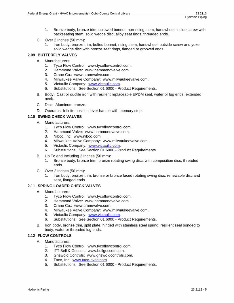
Federal Energy Grant - HVAC Improvements - Cobb County Central Library 23 2113 Hydronic Piping
1. Bronze body, bronze trim, screwed bonnet, non-rising stem, handwheel, inside screw with backseating stem, solid wedge disc, alloy seat rings, threaded ends.
C. Over 2 Inches (50 mm): 1. Iron body, bronze trim, bolted bonnet, rising stem, handwheel, outside screw and yoke,
solid wedge disc with bronze seat rings, flanged or grooved ends.
2.09 BUTTERFLY VALVES
A. Manufacturers: 1. Tyco Flow Control: www.tycoflowcontrol.com. 2. Hammond Valve: www.hammondvalve.com. 3. Crane Co.: www.cranevalve.com. 4. Milwaukee Valve Company: www.milwaukeevalve.com. 5. Victaulic Company: www.victaulic.com. 6. Substitutions: See Section 01 6000 - Product Requirements.
B. Body: Cast or ductile iron with resilient replaceable EPDM seat, wafer or lug ends, extended neck.
C. Disc: Aluminum bronze.
D. Operator: Infinite position lever handle with memory stop.
2.10 SWING CHECK VALVES
A. Manufacturers: 1. Tyco Flow Control: www.tycoflowcontrol.com. 2. Hammond Valve: www.hammondvalve.com. 3. Nibco, Inc: www.nibco.com. 4. Milwaukee Valve Company: www.milwaukeevalve.com. 5. Victaulic Company: www.victaulic.com. 6. Substitutions: See Section 01 6000 - Product Requirements.
B. Up To and Including 2 Inches (50 mm): 1. Bronze body, bronze trim, bronze rotating swing disc, with composition disc, threaded
ends.
C. Over 2 Inches (50 mm): 1. Iron body, bronze trim, bronze or bronze faced rotating swing disc, renewable disc and
seat, flanged ends.
2.11 SPRING LOADED CHECK VALVES
A. Manufacturers: 1. Tyco Flow Control: www.tycoflowcontrol.com. 2. Hammond Valve: www.hammondvalve.com. 3. Crane Co.: www.cranevalve.com. 4. Milwaukee Valve Company: www.milwaukeevalve.com. 5. Victaulic Company: www.victaulic.com. 6. Substitutions: See Section 01 6000 - Product Requirements.
B. Iron body, bronze trim, split plate, hinged with stainless steel spring, resilient seal bonded to body, wafer or threaded lug ends.
2.12 FLOW CONTROLS
A. Manufacturers: 1. Tyco Flow Control: www.tycoflowcontrol.com. 2. ITT Bell & Gossett: www.bellgossett.com. 3. Griswold Controls: www.griswoldcontrols.com. 4. Taco, Inc: www.taco-hvac.com. 5. Substitutions: See Section 01 6000 - Product Requirements.
Hydronic Piping 23 2113 - 5

Federal Energy Grant - HVAC Improvements - Cobb County Central Library 23 2113 Hydronic Piping
B. Construction: Class 150, Brass or bronze body with union on inlet and outlet, temperature and pressure test plug on inlet , blowdown/backflush drain.
C. Calibration: Control flow within 5 percent of selected rating, over operating pressure range of 10 times minimum pressure required for control, maximum minimum pressure 3.5 psi psi (24 kPa kPa).
PART 3 EXECUTION
3.01 PREPARATION
A. Ream pipe and tube ends. Remove burrs.
B. Prepare pipe for grooved mechanical joints as required by coupling manufacturer.
C. Remove scale and dirt on inside and outside before assembly.
D. Prepare piping connections to equipment using jointing system specified.
E. Keep open ends of pipe free from scale and dirt. Protect open ends with temporary plugs or caps.
F. After completion, fill, clean, and treat systems. Refer to Section 23 2500 for additional requirements.
3.02 INSTALLATION
A. Install in accordance with manufacturer's instructions.
B. Install heating water, chilled water, condenser water, to ASME B31.9 requirements. Install chilled water piping to ASME B31.5 requirements.
C. Route piping in orderly manner, parallel to building structure, and maintain gradient.
D. Install piping to conserve building space and to avoid interfere with use of space.
E. Group piping whenever practical at common elevations.
F. Sleeve pipe passing through partitions, walls and floors.
G. Slope piping and arrange to drain at low points.
H. Install piping to allow for expansion and contraction without stressing pipe, joints, or connected equipment. Refer to Section 23 0516.
I. Pipe Hangers and Supports: 1. Install in accordance with ASME B31.9. 2. Support horizontal piping as scheduled. 3. Install hangers to provide minimum 1/2 inch (13 mm) space between finished covering
and adjacent work. 4. Place hangers within 12 inches (300 mm) of each horizontal elbow. 5. Use hangers with 1-1/2 inch (38 mm) minimum vertical adjustment. Design hangers for
pipe movement without disengagement of supported pipe. 6. Where several pipes can be installed in parallel and at same elevation, provide multiple or
trapeze hangers. 7. Provide copper plated hangers and supports for copper piping.
J. Provide clearance in hangers and from structure and other equipment for installation of insulation and access to valves and fittings. Refer to Section 23 0719.
K. Use eccentric reducers to maintain top of pipe level.
L. Where pipe support members are welded to structural building framing, scrape, brush clean, and apply one coat of zinc rich primer to welds.
M. Prepare unfinished pipe, fittings, supports, and accessories, ready for finish painting. Refer to Section 09 9000.
N. Install valves with stems upright or horizontal, not inverted.
3.03 SCHEDULES
A. Hanger Spacing for Copper Tubing.
Hydronic Piping 23 2113 - 6

Federal Energy Grant - HVAC Improvements - Cobb County Central Library 23 2113 Hydronic Piping
Hydronic Piping 23 2113 - 7
1. 1/2 inch (15 mm) and 3/4 inch (20 mm): Maximum span, 5 feet (1500 mm); minimum rod size, 1/4 inch (6 mm).
2. 1 inch (25 mm): Maximum span, 6 feet (1800 mm); minimum rod size, 1/4 inch (6 mm). 3. 1-1/2 inch (40 mm) and 2 inch (50 mm): Maximum span, 8 feet (2400 mm); minimum rod
size, 3/8 inch (9 mm). 4. 2-1/2 inch (65 mm): Maximum span, 9 feet (2700 mm); minimum rod size, 3/8 inch (9
mm).
B. Hanger Spacing for Steel Piping. 1. 1/2 inch (15 mm), 3/4 inch (20 mm), and 1 inch (25 mm): Maximum span, 7 feet (2100
mm); minimum rod size, 1/4 inch (6 mm). 2. 1-1/4 inches (32 mm): Maximum span, 8 feet (2400 mm); minimum rod size, 3/8 inch (9
mm). 3. 1-1/2 inches (40 mm): Maximum span, 9 feet (2700 mm); minimum rod size, 3/8 inch (9
mm). 4. 2 inches (50 mm): Maximum span, 10 feet (3.0 m); minimum rod size, 3/8 inch (9 mm). 5. 2-1/2 inches (65 mm): Maximum span, 11 feet (3.4 m); minimum rod size, 3/8 inch (9
mm). 6. 3 inches (80 mm): Maximum span, 12 feet (3.6 m); minimum rod size, 3/8 inch (9 mm). 7. 4 inches (100 mm): Maximum span, 14 feet (4.3 m); minimum rod size, 1/2 inch (13 mm). 8. 6 inches (150 mm): Maximum span, 17 feet (5.1 m); minimum rod size, 1/2 inch (13 mm).
END OF SECTION

Federal Energy Grant - HVAC Improvements - Cobb County Central Library 23 2114 Hydronic Specialties
SECTION 23 2114
HYDRONIC SPECIALTIES
PART 1 GENERAL
1.01 SECTION INCLUDES
A. Expansion tanks.
B. Air vents.
C. Air separators.
D. Strainers.
E. Pump suction fittings.
F. Combination fittings.
G. Relief valves.
1.02 RELATED REQUIREMENTS
A. Section 23 2113 - Hydronic Piping.
B. Section 23 2500 - HVAC Water Treatment: Pipe Cleaning.
1.03 REFERENCE STANDARDS
A. ASME (BPV VIII, 1) - Boiler and Pressure Vessel Code, Section VIII, Division 1 - Rules for Construction of Pressure Vessels; The American Society of Mechanical Engineers; 2007.
1.04 SUBMITTALS
A. See Section 01 3000 - Administrative Requirements, for submittal procedures.
B. Product Data: Provide product data for manufactured products and assemblies required for this project. Include component sizes, rough-in requirements, service sizes, and finishes. Include product description, model and dimensions.
C. Certificates: Inspection certificates for pressure vessels from authority having jurisdiction.
D. Manufacturer's Installation Instructions: Indicate hanging and support methods, joining procedures.
E. Maintenance Contract.
F. Project Record Documents: Record actual locations of flow controls.
G. Maintenance Data: Include installation instructions, assembly views, lubrication instructions, and replacement parts list.
H. Maintenance Materials: Furnish the following for Owner's use in maintenance of project. 1. See Section 01 6000 - Product Requirements, for additional provisions.
1.05 QUALITY ASSURANCE
A. Manufacturer Qualifications: Company specializing in manufacturing the type of products specified in this section, with minimum three years of documented experience.
1.06 DELIVERY, STORAGE, AND HANDLING
A. Accept valves on site in shipping containers with labeling in place. Inspect for damage.
B. Provide temporary protective coating on cast iron and steel valves.
C. Provide temporary end caps and closures on piping and fittings. Maintain in place until installation.
D. Protect piping systems from entry of foreign materials by temporary covers, completing sections of the work, and isolating parts of completed system.
PART 2 PRODUCTS
2.01 DIAPHRAGM-TYPE EXPANSION TANKS
Hydronic Specialties 23 2114 - 1
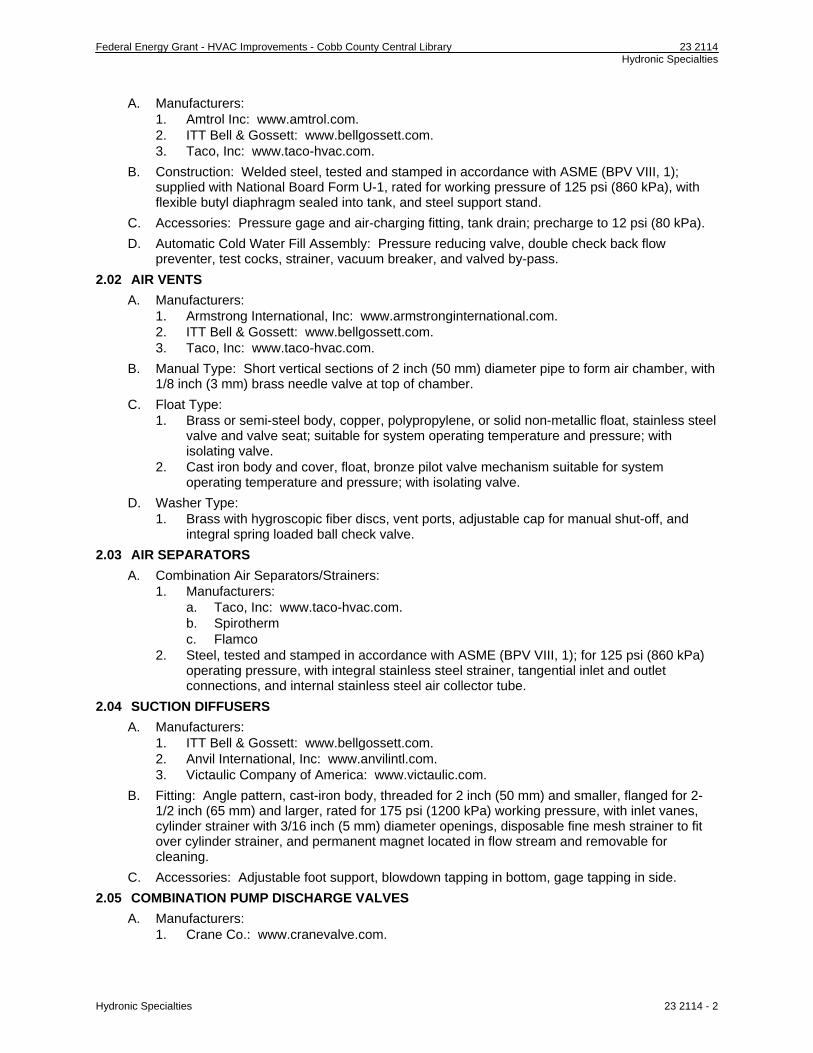
Federal Energy Grant - HVAC Improvements - Cobb County Central Library 23 2114 Hydronic Specialties
A. Manufacturers: 1. Amtrol Inc: www.amtrol.com. 2. ITT Bell & Gossett: www.bellgossett.com. 3. Taco, Inc: www.taco-hvac.com.
B. Construction: Welded steel, tested and stamped in accordance with ASME (BPV VIII, 1); supplied with National Board Form U-1, rated for working pressure of 125 psi (860 kPa), with flexible butyl diaphragm sealed into tank, and steel support stand.
C. Accessories: Pressure gage and air-charging fitting, tank drain; precharge to 12 psi (80 kPa).
D. Automatic Cold Water Fill Assembly: Pressure reducing valve, double check back flow preventer, test cocks, strainer, vacuum breaker, and valved by-pass.
2.02 AIR VENTS
A. Manufacturers: 1. Armstrong International, Inc: www.armstronginternational.com. 2. ITT Bell & Gossett: www.bellgossett.com. 3. Taco, Inc: www.taco-hvac.com.
B. Manual Type: Short vertical sections of 2 inch (50 mm) diameter pipe to form air chamber, with 1/8 inch (3 mm) brass needle valve at top of chamber.
C. Float Type: 1. Brass or semi-steel body, copper, polypropylene, or solid non-metallic float, stainless steel
valve and valve seat; suitable for system operating temperature and pressure; with isolating valve.
2. Cast iron body and cover, float, bronze pilot valve mechanism suitable for system operating temperature and pressure; with isolating valve.
D. Washer Type: 1. Brass with hygroscopic fiber discs, vent ports, adjustable cap for manual shut-off, and
integral spring loaded ball check valve.
2.03 AIR SEPARATORS
A. Combination Air Separators/Strainers: 1. Manufacturers:
a. Taco, Inc: www.taco-hvac.com. b. Spirotherm c. Flamco
2. Steel, tested and stamped in accordance with ASME (BPV VIII, 1); for 125 psi (860 kPa) operating pressure, with integral stainless steel strainer, tangential inlet and outlet connections, and internal stainless steel air collector tube.
2.04 SUCTION DIFFUSERS
A. Manufacturers: 1. ITT Bell & Gossett: www.bellgossett.com. 2. Anvil International, Inc: www.anvilintl.com. 3. Victaulic Company of America: www.victaulic.com.
B. Fitting: Angle pattern, cast-iron body, threaded for 2 inch (50 mm) and smaller, flanged for 2-1/2 inch (65 mm) and larger, rated for 175 psi (1200 kPa) working pressure, with inlet vanes, cylinder strainer with 3/16 inch (5 mm) diameter openings, disposable fine mesh strainer to fit over cylinder strainer, and permanent magnet located in flow stream and removable for cleaning.
C. Accessories: Adjustable foot support, blowdown tapping in bottom, gage tapping in side.
2.05 COMBINATION PUMP DISCHARGE VALVES
A. Manufacturers: 1. Crane Co.: www.cranevalve.com.
Hydronic Specialties 23 2114 - 2
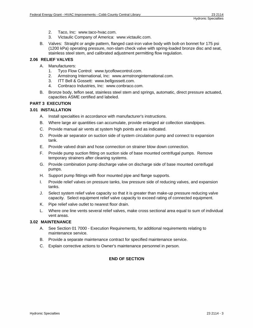
Federal Energy Grant - HVAC Improvements - Cobb County Central Library 23 2114 Hydronic Specialties
Hydronic Specialties 23 2114 - 3
2. Taco, Inc: www.taco-hvac.com. 3. Victaulic Company of America: www.victaulic.com.
B. Valves: Straight or angle pattern, flanged cast-iron valve body with bolt-on bonnet for 175 psi (1200 kPa) operating pressure, non-slam check valve with spring-loaded bronze disc and seat, stainless steel stem, and calibrated adjustment permitting flow regulation.
2.06 RELIEF VALVES
A. Manufacturers: 1. Tyco Flow Control: www.tycoflowcontrol.com. 2. Armstrong International, Inc: www.armstronginternational.com. 3. ITT Bell & Gossett: www.bellgossett.com. 4. Conbraco Industries, Inc: www.conbraco.com.
B. Bronze body, teflon seat, stainless steel stem and springs, automatic, direct pressure actuated, capacities ASME certified and labeled.
PART 3 EXECUTION
3.01 INSTALLATION
A. Install specialties in accordance with manufacturer's instructions.
B. Where large air quantities can accumulate, provide enlarged air collection standpipes.
C. Provide manual air vents at system high points and as indicated.
D. Provide air separator on suction side of system circulation pump and connect to expansion tank.
E. Provide valved drain and hose connection on strainer blow down connection.
F. Provide pump suction fitting on suction side of base mounted centrifugal pumps. Remove temporary strainers after cleaning systems.
G. Provide combination pump discharge valve on discharge side of base mounted centrifugal pumps.
H. Support pump fittings with floor mounted pipe and flange supports.
I. Provide relief valves on pressure tanks, low pressure side of reducing valves, and expansion tanks.
J. Select system relief valve capacity so that it is greater than make-up pressure reducing valve capacity. Select equipment relief valve capacity to exceed rating of connected equipment.
K. Pipe relief valve outlet to nearest floor drain.
L. Where one line vents several relief valves, make cross sectional area equal to sum of individual vent areas.
3.02 MAINTENANCE
A. See Section 01 7000 - Execution Requirements, for additional requirements relating to maintenance service.
B. Provide a separate maintenance contract for specified maintenance service.
C. Explain corrective actions to Owner's maintenance personnel in person.
END OF SECTION

Federal Energy Grant - HVAC Improvements - Cobb County Central Library 23 2123 Hydronic Pumps
SECTION 23 2123
HYDRONIC PUMPS
PART 1 GENERAL
1.01 SECTION INCLUDES
A. In-line circulators.
B. Base mounted pumps.
1.02 RELATED REQUIREMENTS
A. Section 03 3000 - Cast-in-Place Concrete.
B. Section 23 0513 - Common Motor Requirements for HVAC Equipment.
C. Section 23 0548 - Vibration and Seismic Controls for HVAC Piping and Equipment.
D. Section 23 0719 - HVAC Piping Insulation.
E. Section 23 2113 - Hydronic Piping.
F. Section 23 2114 - Hydronic Specialties.
G. Section 26 2717 - Equipment Wiring: Electrical characteristics and wiring connections.
1.03 REFERENCE STANDARDS
A. NEMA MG 1 - Motors and Generators; National Electrical Manufacturers Association; 2007.
B. NEMA OS 1 - Sheet Steel Outlet Boxes, Device Boxes, Covers, and Box Supports; National Electrical Manufacturers Association; 2008.
C. NFPA 70 - National Electrical Code; National Fire Protection Association; 2008.
D. UL 778 - Standard for Motor-Operated Water Pumps; Underwriters Laboratories Inc.; Current Edition, Including All Revisions.
1.04 SUBMITTALS
A. See Section 01 3000 - Administrative Requirements, for submittal procedures.
B. Product Data: Provide certified pump curves showing performance characteristics with pump and system operating point plotted. Include NPSH curve when applicable. Include electrical characteristics and connection requirements.
C. Manufacturer's Installation Instructions: Indicate hanging and support requirements and recommendations.
D. Millwright's Certificate: Certify that base mounted pumps have been aligned.
E. Operation and Maintenance Data: Include installation instructions, assembly views, lubrication instructions, and replacement parts list.
F. Maintenance Materials: Furnish the following for Owner's use in maintenance of project. 1. See Section 01 6000 - Product Requirements, for additional provisions. 2. Extra Pump Seals: One set for each type and size of pump. 3. Extra Cartridges for Side-Stream Filters: One set for each filter.
1.05 QUALITY ASSURANCE
A. Manufacturer Qualifications: Company specializing in manufacture, assembly, and field performance of pumps, with minimum three years of documented experience.
PART 2 PRODUCTS
2.01 MANUFACTURERS
A. Armstrong Pumps Inc: www.armstrongpumps.com.
B. ITT Bell & Gossett: www.bellgossett.com.
C. Sterling Fluid Systems: www.sterlingfluid.com.
Hydronic Pumps 23 2123 - 1

Federal Energy Grant - HVAC Improvements - Cobb County Central Library 23 2123 Hydronic Pumps
D. Taco, Inc: www.taco-hvac.com.
E. Substitutions: See Section 01 6000 - Product Requirements.
2.02 HVAC PUMPS - GENERAL
A. Provide pumps that operate at specified system fluid temperatures without vapor binding and cavitation, are non-overloading in parallel or individual operation, and operate within 25 percent of midpoint of published maximum efficiency curve.
B. Minimum Quality Standard: UL 778.
C. Base Mounted Pumps: Aligned by qualified millwright.
D. Products Requiring Electrical Connection: Listed and classified by UL as suitable for the purpose specified and indicated.
2.03 IN-LINE CIRCULATORS
A. Type: Horizontal shaft, single stage, direct connected, with resiliently mounted motor for in-line mounting, oil lubricated, for 175 psi (1200 kPa) maximum working pressure.
B. Casing: Cast iron, with flanged pump connections.
C. Impeller: Bronze keyed to shaft.
D. Bearings: Permanently-lubricated ball bearings.
E. Shaft: Carbon steel with bronze sleeve, integral thrust collar.
F. Seal: Mechanical seal, 250 degrees F (121 degrees C) maximum continuous operating temperature.
G. Drive: Flexible coupling.
H. Performance: See Pump Schedule.
I. Electrical Characteristics: See Pump Schedule.
2.04 BASE MOUNTED PUMPS
A. Type: Horizontal shaft, single stage, direct connected, radially split casing, for 175 psi (1200 kPa) maximum working pressure.
B. Casing: Cast iron, with suction and discharge gage ports, renewable bronze casing wearing rings, seal flush connection, drain plug, flanged suction and discharge.
C. Impeller: Bronze, fully enclosed, keyed to shaft.
D. Bearings: Permanently lubricated roller or ball bearings.
E. Shaft: Alloy steel with copper, bronze, or stainless steel shaft sleeve.
F. Seal: Carbon rotating against a stationary ceramic seat, 225 degrees F (107 degrees C) maximum continuous operating temperature.
G. Seal: Packing gland with minimum four rings graphite impregnated packing and bronze lantern rings, 250 degrees F (121 degrees C) maximum continuous operating temperature.
H. Drive: Flexible coupling with coupling guard.
I. Baseplate: Cast iron or fabricated steel with integral drain rim.
J. Performance: See Pump Schedule.
K. Electrical Characteristics: See Pump Schedule.
PART 3 EXECUTION
3.01 PREPARATION
A. Verify that electric power is available and of the correct characteristics.
3.02 INSTALLATION
A. Install in accordance with manufacturer's instructions.
Hydronic Pumps 23 2123 - 2

Federal Energy Grant - HVAC Improvements - Cobb County Central Library 23 2123 Hydronic Pumps
Hydronic Pumps 23 2123 - 3
B. Provide access space around pumps for service. Provide no less than minimum space recommended by manufacturer.
C. Decrease from line size with long radius reducing elbows or reducers. Support piping adjacent to pump such that no weight is carried on pump casings. For close coupled or base mounted pumps, provide supports under elbows on pump suction and discharge line sizes 4 inches (102 mm) and over.
D. Provide line sized shut-off valve and strainer; pump suction fitting on pump suction, and line sized combination pump discharge valve on pump discharge.
E. Provide air cock and drain connection on horizontal pump casings.
F. Provide drains for bases and seals, piped to and discharging into floor drains.
G. Check, align, and certify alignment of base mounted pumps prior to start-up.
H. Install base mounted pumps on concrete housekeeping base, with anchor bolts, set and level, and grout in place.
I. Lubricate pumps before start-up.
J. Provide side-stream filtration system for closed loop systems. Install across pump with flow from pump discharge to pump suction from pump tappings.
END OF SECTION

Federal Energy Grant - HVAC Improvements - Cobb County Central Library 23 2500 HVAC Water Treatment
SECTION 23 2500
HVAC WATER TREATMENT
PART 1 GENERAL
1.01 SECTION INCLUDES
A. Cleaning of piping systems.
B. Chemical feeder equipment.
C. Chemical treatment.
1.02 RELATED REQUIREMENTS
A. Section 23 2113 - Hydronic Piping.
B. Section 23 2114 - Hydronic Specialties.
C. Section 23 0913 - Instrumentation and Control Devices for HVAC.
D. Section 26 2717 - Equipment Wiring: Electrical characteristics and wiring connections.
1.03 SUBMITTALS
A. See Section 01 3000 - Administrative Requirements, for submittal procedures.
B. Product Data: Provide chemical treatment materials, chemicals, and equipment including electrical characteristics and connection requirements.
C. Shop Drawings: Indicate system schematic, equipment locations, and controls schematics, electrical characteristics and connection requirements.
D. Manufacturer's Installation Instructions: Indicate placement of equipment in systems, piping configuration, and connection requirements.
E. Manufacturer's Field Reports: Indicate start-up of treatment systems when completed and operating properly. Indicate analysis of system water after cleaning and after treatment.
F. Certificate: Submit certificate of compliance from authority having jurisdiction indicating approval of chemicals and their proposed disposal.
G. Project Record Documents: Record actual locations of equipment and piping, including sampling points and location of chemical injectors.
H. Operation and Maintenance Data: Include data on chemical feed pumps, agitators, and other equipment including spare parts lists, procedures, and treatment programs. Include step by step instructions on test procedures including target concentrations.
I. Maintenance Materials: Furnish the following for Owner's use in maintenance of project. 1. See Section 01 6000 - Product Requirements, for additional provisions. 2. Sufficient chemicals for treatment and testing during required maintenance period.
1.04 QUALITY ASSURANCE
A. Manufacturer Qualifications: Company specializing in manufacturing the type of products specified in this section, with minimum ten years of experience. Company shall have local representatives with water analysis laboratories and full time service personnel.
B. Installer Qualifications: Company specializing in performing the type of work specified in this section, with minimum 10 years of experience and approved by manufacturer.
1.05 REGULATORY REQUIREMENTS
A. Conform to applicable code for addition of non-potable chemicals to building mechanical systems and to public sewage systems.
B. Products Requiring Electrical Connection: Listed and classified by UL as suitable for the purpose specified and indicated.
HVAC Water Treatment 23 2500 - 1
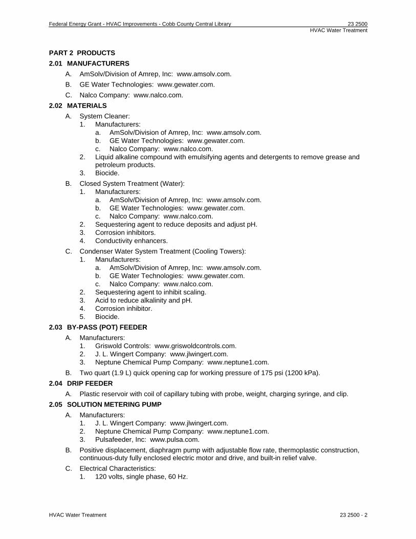
Federal Energy Grant - HVAC Improvements - Cobb County Central Library 23 2500 HVAC Water Treatment
PART 2 PRODUCTS
2.01 MANUFACTURERS
A. AmSolv/Division of Amrep, Inc: www.amsolv.com.
B. GE Water Technologies: www.gewater.com.
C. Nalco Company: www.nalco.com.
2.02 MATERIALS
A. System Cleaner: 1. Manufacturers:
a. AmSolv/Division of Amrep, Inc: www.amsolv.com. b. GE Water Technologies: www.gewater.com. c. Nalco Company: www.nalco.com.
2. Liquid alkaline compound with emulsifying agents and detergents to remove grease and petroleum products.
3. Biocide.
B. Closed System Treatment (Water): 1. Manufacturers:
a. AmSolv/Division of Amrep, Inc: www.amsolv.com. b. GE Water Technologies: www.gewater.com. c. Nalco Company: www.nalco.com.
2. Sequestering agent to reduce deposits and adjust pH. 3. Corrosion inhibitors. 4. Conductivity enhancers.
C. Condenser Water System Treatment (Cooling Towers): 1. Manufacturers:
a. AmSolv/Division of Amrep, Inc: www.amsolv.com. b. GE Water Technologies: www.gewater.com. c. Nalco Company: www.nalco.com.
2. Sequestering agent to inhibit scaling. 3. Acid to reduce alkalinity and pH. 4. Corrosion inhibitor. 5. Biocide.
2.03 BY-PASS (POT) FEEDER
A. Manufacturers: 1. Griswold Controls: www.griswoldcontrols.com. 2. J. L. Wingert Company: www.jlwingert.com. 3. Neptune Chemical Pump Company: www.neptune1.com.
B. Two quart (1.9 L) quick opening cap for working pressure of 175 psi (1200 kPa).
2.04 DRIP FEEDER
A. Plastic reservoir with coil of capillary tubing with probe, weight, charging syringe, and clip.
2.05 SOLUTION METERING PUMP
A. Manufacturers: 1. J. L. Wingert Company: www.jlwingert.com. 2. Neptune Chemical Pump Company: www.neptune1.com. 3. Pulsafeeder, Inc: www.pulsa.com.
B. Positive displacement, diaphragm pump with adjustable flow rate, thermoplastic construction, continuous-duty fully enclosed electric motor and drive, and built-in relief valve.
C. Electrical Characteristics: 1. 120 volts, single phase, 60 Hz.
HVAC Water Treatment 23 2500 - 2

Federal Energy Grant - HVAC Improvements - Cobb County Central Library 23 2500 HVAC Water Treatment
2. Cord and Plug: Provide unit with 6 foot (2 m) cord and plug for connection to electric wiring system including grounding connector.
2.06 SOLUTION TANKS
A. 50 gallon (189 L) capacity, polyethylene, self-supporting, 5 gallon (19 L) graduated markings; molded fiberglass cover with recess for mounting pump, agitator, and liquid level switch.
2.07 AGITATOR
A. Totally enclosed electric motor, cast iron clamp and motor mount, Type 316 stainless steel propeller.
B. Electrical Characteristics: 1. 120 volts, single phase, 60 Hz. 2. Cord and Plug: Provide unit with 6 foot (2 m) cord and plug for connection to electric
wiring system including grounding connector.
2.08 LIQUID LEVEL SWITCH
A. Polypropylene housing with integrally mounted PVC air trap, receptacles for connection to metering pump, and low level alarm.
2.09 CONDUCTIVITY CONTROLLER
A. Manufacturers: 1. Envirocare: www.envirocare.com. 2. JENCO Instruments Incorporated: www.jencoi.com. 3. Omega Engineering, Inc: www.omega.com.
B. Packaged monitor controller with solid state circuiting, five percent accuracy, linear dial adjustment, built-in calibration switch, on-off switch and light, control function light, output to control circuit.
2.10 WATER METER
A. Displacement type cold water meter with sealed, tamper-proof magnetic drive, impulse contact register, single pole, double throw dry contact switch.
2.11 SOLENOID VALVES
A. Forged brass body globe pattern, normally open or closed as required, general purpose solenoid enclosure, and continuous duty coil.
2.12 TIMERS
A. Electronic timers, infinitely adjustable over full range, 150 second and five minute range, mounted together in cabinet with hands-off-automatic switches and status lights.
2.13 TEST EQUIPMENT
A. Provide the following test kits: 1. Alkalinity titration test kit. 2. Chloride titration test kit. 3. Sulphite titration test kit. 4. Total hardness titration test kit. 5. Low phosphate test kit. 6. Conductivity bridge, range 0 - 10,000 micro-ohms. 7. Creosol red pH slide complete with reagent. 8. Portable electronic conductivity meter. 9. High nitrite test kit.
PART 3 EXECUTION
3.01 PREPARATION
A. Systems shall be operational, filled, started, and vented prior to cleaning. Use water meter to record capacity in each system.
B. Place terminal control valves in open position during cleaning.
HVAC Water Treatment 23 2500 - 3

Federal Energy Grant - HVAC Improvements - Cobb County Central Library 23 2500 HVAC Water Treatment
C. Verify that electric power is available and of the correct characteristics.
3.02 CLEANING SEQUENCE
A. Concentration: 1. As recommended by manufacturer.
B. Hot Water Heating Systems: 1. Apply heat while circulating, slowly raising temperature to 160 degrees F (71 degrees C)
and maintain for 12 hours minimum. 2. Remove heat and circulate to 100 degrees F (37.8 degrees C) or less; drain systems as
quickly as possible and refill with clean water. 3. Circulate for 6 hours at design temperatures, then drain. 4. Refill with clean water and repeat until system cleaner is removed.
C. Chilled Water Systems: 1. Circulate for 48 hours, then drain systems as quickly as possible. 2. Refill with clean water, circulate for 24 hours, then drain. 3. Refill with clean water and repeat until system cleaner is removed.
D. Use neutralizer agents on recommendation of system cleaner supplier and approval of Engineer.
E. Flush open systems with clean water for one hour minimum. Drain completely and refill.
F. Remove, clean, and replace strainer screens.
G. Inspect, remove sludge, and flush low points with clean water after cleaning process is completed. Include disassembly of components as required.
3.03 INSTALLATION
A. Install in accordance with manufacturer's instructions.
3.04 CLOSED SYSTEM TREATMENT
A. Provide one bypass feeder on each system. Install isolating and drain valves and necessary piping. Install around balancing valve downstream of circulating pumps unless indicated otherwise.
B. Introduce closed system treatment through bypass feeder when required or indicated by test.
C. Provide 3/4 inch (19 mm) water coupon rack around circulating pumps with space for 12 test specimens.
3.05 CONDENSER WATER SYSTEMS (COOLING TOWERS)
A. Provide solution pumps to feed sequestering agent and corrosion inhibitor from solution tank into condenser water supply to tower. Provide agitator as required.
B. Provide conductivity controller to sample condenser water and operate 1 inch (25 mm) solenoid bleed valve and solution pumps. Provide 1/4 inch (6 mm) solenoid valve and piping to blowdown controller sampler wired to open when condensing water pump is operating.
C. Provide solution pump to feed diluted acid from solution tank into condenser water supply to tower.
D. Introduce algicide to tower by solenoid valve on tank (chlorine).
E. Provide water meter in make-up water line to tower, to activate solution pumps for preset time when condenser water pumps are running.
F. Provide liquid level switch in each solution tank to de- activate solution pump and agitator, and sound local alarm bell.
G. Provide 3/4 inch (19 mm) water coupon rack around circulating pumps with space for 12 test specimens.
HVAC Water Treatment 23 2500 - 4

Federal Energy Grant - HVAC Improvements - Cobb County Central Library 23 2500 HVAC Water Treatment
HVAC Water Treatment 23 2500 - 5
3.06 CLOSEOUT ACTIVITIES
A. Training: Train Owner's personnel on operation and maintenance of chemical treatment system. 1. Provide minimum of two hours of instruction for two people. 2. Have operation and maintenance data prepared and available for review during training. 3. Conduct training using actual equipment after treated system has been put into full
operation.
3.07 MAINTENANCE
A. See Section 01 7000 - Execution Requirements, for additional requirements relating to maintenance service.
B. Provide a separate maintenance contract for specified maintenance service.
C. Perform maintenance work using competent and qualified personnel of the equipment manufacturer or original installer.
D. Maintenance service shall not be assigned or transferred to any agent or subcontractor without prior written consent of Owner.
E. Provide service and maintenance of treatment systems for one year from Date of Substantial Completion.
F. Provide monthly technical service visits to perform field inspections and make water analysis on site. Detail findings in writing on proper practices, chemical treating requirements, and corrective actions needed. Submit two copies of field service report after each visit.
G. Provide laboratory and technical assistance services during this maintenance period.
H. Provide on site inspections of equipment during scheduled or emergency shutdown to properly evaluate success of water treatment program, and make recommendations in writing based upon these inspections.
END OF SECTION

Federal Energy Grant - HVAC Improvements - Cobb County Central Library 23 3100 HVAC Ducts And Casings
SECTION 23 3100
HVAC DUCTS AND CASINGS
PART 1 GENERAL
1.01 SECTION INCLUDES
A. Metal ductwork.
B. Casing and plenums.
C. Duct cleaning.
1.02 RELATED REQUIREMENTS
A. Section 23 0713 - Duct Insulation: External insulation and duct liner.
B. Section 23 3300 - Air Duct Accessories.
C. Section 23 0593 - Testing, Adjusting, and Balancing for HVAC.
1.03 REFERENCE STANDARDS
A. ASHRAE (FUND) - ASHRAE Handbook - Fundamentals; 2005.
B. ASTM A 36/A 36M - Standard Specification for Carbon Structural Steel; 2005.
C. ASTM A 653/A 653M - Standard Specification for Steel Sheet, Zinc-Coated (Galvanized) or Zinc-Iron Alloy-Coated (Galvannealed) by the Hot-Dip Process; 2009.
D. ASTM A 1008/A 1008M - Standard Specification for Steel, Sheet, Cold-Rolled, Carbon, Structural, High-Strength, Low Alloy, and High-Strength Low-Alloy with Improved Formability, Solution Hardened, and Bake Hardenable; 2007a
E. ASTM A 1011/A 1011M - Standard Specification for Steel, Sheet and Strip, Hot-Rolled, Carbon, Structural, High-Strength Low Alloy, High-Strength Low-Alloy With Improved Formability, and Ultra-High Strength; 2008
F. ASTM E 84 - Standard Test Method for Surface Burning Characteristics of Building Materials; 2010.
G. NFPA 90A - Standard for the Installation of Air-Conditioning and Ventilating Systems; National Fire Protection Association; 2009.
H. NFPA 90B - Standard for the Installation of Warm Air Heating and Air Conditioning Systems; National Fire Protection Association; 2009.
I. SMACNA (LEAK) - HVAC Air Duct Leakage Test Manual; Sheet Metal and Air Conditioning Contractors' National Association; 1985, First Edition.
J. SMACNA (DCS) - HVAC Duct Construction Standards - Metal and Flexible; Sheet Metal and Air Conditioning Contractors' National Association; 2005.
K. UL 181 - Standard for Factory-Made Air Ducts and Air Connectors; Underwriters Laboratories Inc.; Current Edition.
1.04 SUBMITTALS
A. See Section 01 3000 - Administrative Requirements, for submittal procedures.
B. Shop Drawings: Indicate duct fittings, particulars such as gages, sizes, welds, and configuration prior to start of work.
C. Test Reports: Indicate pressure tests performed. Include date, section tested, test pressure, and leakage rate, following SMACNA (LEAK) - HVAC Air Duct Leakage Test Manual.
D. Project Record Documents: Record actual locations of ducts and duct fittings. Record changes in fitting location and type. Show additional fittings used.
1.05 QUALITY ASSURANCE
HVAC Ducts And Casings 23 3100 - 1

Federal Energy Grant - HVAC Improvements - Cobb County Central Library 23 3100 HVAC Ducts And Casings
A. Manufacturer Qualifications: Company specializing in manufacturing the type of products specified in this section, with minimum 5 years of documented experience.
B. Installer Qualifications: Company specializing in performing the type of work specified in this section, with minimum 5 years of documented experience.
1.06 REGULATORY REQUIREMENTS
A. Construct ductwork to NFPA 90A standards.
1.07 FIELD CONDITIONS
A. Do not install duct sealants when temperatures are less than those recommended by sealant manufacturers.
B. Maintain temperatures within acceptable range during and after installation of duct sealants.
PART 2 PRODUCTS
2.01 DUCT ASSEMBLIES
A. All Ducts: Galvanized steel, unless otherwise indicated.
B. Medium and High Pressure Supply: pressure class, galvanized steel.
C. Return and Relief: 1 inch w.g. (250 Pa) pressure class, galvanized steel.
2.02 MATERIALS
A. Galvanized Steel for Ducts: Hot-dipped galvanized steel sheet, ASTM A 653/A 653M FS Type B, with G60/Z180 coating.
B. Joint Sealers and Sealants: Non-hardening, water resistant, mildew and mold resistant. 1. Type: Heavy mastic or liquid used alone or with tape, suitable for joint configuration and
compatible with substrates, and recommended by manufacturer for pressure class of ducts.
2. VOC Content: Not more than 250 g/L, excluding water. 3. Surface Burning Characteristics: Flame spread of zero, smoke developed of zero, when
tested in accordance with ASTM E 84. 4. For Use With Flexible Ducts: UL labeled.
C. Hanger Rod: ASTM A 36/A 36M; steel, galvanized; threaded both ends, threaded one end, or continuously threaded.
2.03 DUCTWORK FABRICATION
A. Fabricate and support in accordance with SMACNA HVAC Duct Construction Standards - Metal and Flexible, and as indicated.
B. No variation of duct configuration or size permitted except by written permission. Size round duct installed in place of rectangular ducts in accordance with ASHRAE Handbook - Fundamentals.
C. Provide duct material, gages, reinforcing, and sealing for operating pressures indicated.
D. Construct T's, bends, and elbows with radius of not less than 1-1/2 times width of duct on certerline. Where not possible and where rectangular elbows must be used, provide turning vanes of perforated metal with glass fiber insulation.
E. Provide turning vanes of perforated metal with glass fiber insulation when acoustical lining is indicated.
F. Increase duct sizes gradually, not exceeding 15 degrees divergence wherever possible; maximum 30 degrees divergence upstream of equipment and 45 degrees convergence downstream.
PART 3 EXECUTION
3.01 INSTALLATION
A. Install, support, and seal ducts in accordance with SMACNA HVAC Duct Construction Standards - Metal and Flexible.
HVAC Ducts And Casings 23 3100 - 2

Federal Energy Grant - HVAC Improvements - Cobb County Central Library 23 3100 HVAC Ducts And Casings
HVAC Ducts And Casings 23 3100 - 3
B. Install in accordance with manufacturer's instructions.
C. During construction provide temporary closures of metal or taped polyethylene on open ductwork to prevent construction dust from entering ductwork system.
D. Duct sizes indicated are inside clear dimensions. For lined ducts, maintain sizes inside lining.
E. Locate ducts with sufficient space around equipment to allow normal operating and maintenance activities.
F. Use double nuts and lock washers on threaded rod supports.
3.02 CLEANING
A. Clean duct system and force air at high velocity through duct to remove accumulated dust. To obtain sufficient air, clean half the system at a time. Protect equipment that could be harmed by excessive dirt with temporary filters, or bypass during cleaning.
B. Clean duct systems with high power vacuum machines. Protect equipment that could be harmed by excessive dirt with filters, or bypass during cleaning. Provide adequate access into ductwork for cleaning purposes.
END OF SECTION
Federal Energy Grant - HVAC Improvements - Cobb County Central Library 23 5200 Aluminum Heating Boilers
SECTION 23 5200
ALUMINUM HEATING BOILERS
PART 1 GENERAL
1.01 SCOPE
A. The work to be performed consists of providing all labor, equipment, materials, etc. to furnish and install new factory assembled, low pressure hot water boilers as described in the specifications herein.
1.02 REFERENCES
A. ASME Section IV (Heating Boilers)
B. ANSI Z21.13/CSA 4.9 (Gas Fired Low Pressure Boilers)
C. NFPA 54 (ANSI Z221.3) National Fuel Gas Code
D. ASME CSD-1 (Controls and Safety Devices)
1.03 QUALITY ASSURANCE
A. The equipment shall, as a minimum, be in strict compliance with the requirements of this specification and shall be the manufacturer’s standard commercial product unless specified otherwise. Additional equipment features, details, accessories, appurtenances, etc. which are not specifically identified but which are a part of the manufacturer’s standard commercial product, shall be included in the equipment being furnished.
B. The equipment shall be of the type, design, and size that the manufacturer currently offers for sale and appears in the manufacturer’s current catalogue.
C. The equipment must fit within the allocated space, leaving ample allowance, as may be required by local or state codes, for maintenance and cleaning, and must leave suitable space for easy removal of all equipment appurtenances.
D. The equipment shall be new and fabricated from new materials. The equipment shall be free from defects in materials and workmanship.
E. All units of the same classification shall be identical to the extent necessary to insure interchangeability of parts, assemblies, accessories, and spare parts wherever possible.
F. In order to provide unit responsibility for the specified capacities, efficiencies, and performance, the boiler manufacturer shall certify in writing that the equipment being submitted shall perform as specified. The boiler manufacturer shall be responsible for guarantying that the boiler provides the performance as specified herein.
1.04 SUBMITTALS
A. The contractor shall submit, in a timely manner, all submittals for approval by the engineer. Under no circumstances shall the contractor install any materials until the engineer has made final approval on the submittals.
B. The engineer shall review, stamp and sign submittals. Work may proceed and equipment released for fabrication after contractor receives returned submittals stamped with “NO EXCEPTIONS TAKEN” or “MAKE CORRECTIONS NOTED”.
C. The bidder must submit in writing to the engineer any request for a proposed deviation, omission, modification, or substitution to this specification for evaluation no later than (10) days prior to the bid date. A request for any substitution shall be accompanied by technical data, drawings, product samples, and complete data substantiating compliance of proposed substitution with these specifications. No materials shall be deemed acceptable if not in strict and full compliance with these specifications. All bidders must bid solely on the specified materials unless acceptance by the engineer of a deviation, omission, modification, or substitution is granted in writing to all bidders prior to the bid date.
Aluminum Heating Boilers 23 5200 - 1
Federal Energy Grant - HVAC Improvements - Cobb County Central Library 23 5200 Aluminum Heating Boilers
D. Shop Drawings. Four (4) copies of the shop drawings shall be submitted to the engineer for approval and shall consist of: 1. General assembly drawing of the boiler including product description, model number,
dimensions, clearances, weights, service sizes, etc. 2. Schematic flow diagram of gas valve trains. 3. Schematic wiring diagram of boiler control system. Schematic wiring diagram shall be
ladder-type showing all components, interlocks, etc. Schematic wiring diagram shall clearly identify factory wiring and field wiring.
E. Installation Instructions: Manufacturer’s printed instructions for installation shall be submitted to the engineer for approval.
F. Boiler Inspector’s Certifications: As specified hereinafter, shall be submitted in writing prior to final acceptance by the engineer.
G. Factory Test Reports: Factory test reports, as specified hereinafter, shall be submitted prior to final acceptance by the engineer.
H. Field Test Reports: Field test reports, as specified hereinafter, shall be submitted prior to final acceptance by the engineer.
I. Operation and Maintenance Manuals: Manufacturer’s printed operation and maintenance manuals shall be submitted prior to final acceptance by the engineer. Operation and maintenance manuals shall contain shop drawings, product data, operating instructions, cleaning procedures, replacement parts list, maintenance and repair data, complete parts lists, etc.
J. Manufacturer’s Warranties: Manufacturer’s printed warranties, as specified hereinafter, shall be submitted prior to final acceptance by the engineer.
K. Manufacturer’s Field Service: Manufacturer’s printed field service procedures shall be submitted prior to final acceptance by the engineer. Field service procedures shall include the name of boiler manufacturer’s field service manager and phone number of boiler manufacturer’s field service department.
1.05 CERTIFICATIONS
A. Manufacturer’s Certification: The boiler manufacturer shall certify the following: 1. The products and systems furnished are in strict compliance with the specifications. 2. The boiler, burner and other associated mechanical and electrical equipment have all
been properly coordinated and integrated to provide a complete and operable boiler. 3. ASME certification. 4. CSA (AGA/CGA) certification. 5. The specified factory tests have been satisfactorily performed. 6. The equipment furnished contains inter-changeable parts with the specified equipment so
that all major equipment parts can be obtained from the specified manufacturer. 7. The Boiler complies with the “Buy American Act.”
B. Contractor’s Certification: The contractor shall certify the following: 1. The products and systems installed are in strict compliance with the specifications and all
applicable local or state codes. 2. The specified field tests have been satisfactorily performed. 3. The equipment furnished contains inter-changeable parts with the specified equipment so
that all major equipment parts can be obtained from the specified manufacturer.
1.06 DELIVERY, STORAGE, AND HANDLING
A. The contractor shall be responsible for the timely delivery of the equipment to the jobsite. The contractor shall be responsible for unloading and rigging of the equipment. The contractor shall be responsible for protecting the equipment from the weather, humidity and temperature conditions, dirt, dust, other contaminants, as well as jobsite conditions during construction.
B. Equipment shall be unloaded, handled, and stored in accordance with the manufacturer’s handling and storage instructions.
Aluminum Heating Boilers 23 5200 - 2

Federal Energy Grant - HVAC Improvements - Cobb County Central Library 23 5200 Aluminum Heating Boilers
PART 2 PRODUCTS
2.01 GENERAL
A. Furnish and install MACH C-2500 (1) factory “packaged” low pressure hot water boilers as manufactured by Patterson-Kelley Co. or as approved and accepted by the engineer. Each factory “packaged” boiler shall be complete with all components, accessories and appurtenances necessary for a complete and operable boiler as hereinafter specified. Each unit shall be furnished factory assembled with required wiring and piping as a self-contained unit. Each unit shall be readily transported and ready for installation.
B. Each factory “packaged” boiler, including pressure vessel, trim, valve trains, burner, control system, and all related components, accessories and appurtenances as herein specified shall all be assembled and furnished by the boiler manufacturer. The boiler manufacturer shall provide unit responsibility for the engineering, coordination, workmanship, performance, warranties, and all field services for each factory “packaged” boiler as specified herein. The boiler manufacturer shall be fully responsible for all components assembled and furnished by him whether or not they are of his own manufacture.
2.02 PERFORMANCE CRITERIA
A. The minimum capacity of each boiler shall be to produce continuously an output of 2,375,000 BTU’s per hour at the water outlet when fired with an input of 2,500,000 BTU’s per hour at sea-level conditions. Each boiler shall be capable of operating continuously at rated capacity while maintaining a CSA certified efficiency of not less than 92%. Each boiler shall be capable of operating with a minimum outlet water temperature of 68 degrees F.
B. Boiler shall comply with ASME Section IV for 80 psig (max 200 degrees F)
C. Boiler relief valve setting shall be 80 psig. (80 psig max.)
D. Boiler outlet water temperature shall be 180 degrees F. (200 degrees F max)
E. Boiler inlet water temperature shall be 160 degrees F.
F. Boiler design water flow rate shall be 205 GPM.
G. Fuel shall be natural gas with an assumed higher heating value of 1,030 Btu/Cu Ft and an assumed specific gravity of 0.60 (relative to air). Natural gas shall be supplied at a pressure of no less than 3.5 inwc to the inlet gas valve. Maximum inlet gas pressure shall not exceed 14 inwc.
H. Ambient air temperature shall be assumed to range from 50 degrees F to 90 degrees F with an average of 70 degrees F.
I. Actual elevation is +/- 1,070 ft above sea-level.
J. Power voltage shall be 120 VAC, 1-phase, 60 hertz. Control voltage shall be 24 VAC (transformer to be supplied by boiler manufacturer.
2.03 BOILER DESIGN
A. Each hot water boiler shall consist of horizontal, cast aluminum heat exchanger complete with trim, valve trains, burner, and boiler control system. The boiler manufacturer shall fully coordinate the boiler as to the interaction of its elements with the burner and the boiler control system in order to provide the required capacities, efficiencies, and performance as specified.
B. Each boiler heat exchanger shall be cast aluminum, counter-flow design for maximum heat transfer with the multiple sections arranged in a reverse return configuration to assure balanced flow through each section.
C. Contractor must, when filling the system, verify that the pH level is maintained between 6.0 and 8.5.
D. All boiler pressure parts shall be constructed in accordance with the latest revision of the ASME Boiler and Pressure Vessel Code, Section IV, and shall be so stamped.
Aluminum Heating Boilers 23 5200 - 3

Federal Energy Grant - HVAC Improvements - Cobb County Central Library 23 5200 Aluminum Heating Boilers
E. Boiler heat exchanger headers shall be fabricated steel and be completely removable for inspection. Seals shall be EPDM, rated for 400 degrees F service. Push nipples or gaskets between the sections are not permitted.
F. Boiler shall be enclosed with a single wall outer casing. It shall be fabricated from a minimum 16 gauge carbon steel. The front and top wall shall be secured in place with ¼ - 20 NC bolts (sheet metal screws are not acceptable). The complete outer casing shall be finished, inside and out, with a powder coat finish. The composite structure of the boiler combustion chamber, insulating air gap and outer casing shall be of such thickness and materials to assure an outer casing temperature of not more than 50 degrees F above ambient temperature when the boiler is operated at full rated load.
G. An observation port shall be located on the boiler to allow for observation of the burner flame.
H. Flue gas outlet shall be located on the rear of the boiler. Boiler to be certified for installation with Category IV venting (stack) as defined in NFPA 54 (ANSI Z221), latest edition. Contractor must provide venting (stack) certified for installation on a Category IV appliance.
2.04 BOILER CONNECTIONS
A. Each boiler shall be provided with all necessary inlet and outlet connections. Boiler connections shall be as follows: 1. One (1) water supply outlet, 3” Victaulic with threaded pipe adapter. 2. One (1) water return inlet, 3” Victaulic with threaded pipe adapter. 3. One (1) relief valve outlet, 1” NPT. 4. One (1) flue gas vent outlet, 10” DIA. 5. One (1) fuel gas inlet, 1-1/2” size, FPT.
2.05 BOILER TRIM
A. Each boiler shall be provided with all necessary trim. Boiler trim shall be as follows: 1. Safety relief valve shall be provided in compliance with the ASME code. Contractor to pipe
to acceptable drain. 2. Water pressure-temperature gauge. 3. Primary low water flow fuel cutoff (probe type with manual reset). 4. Manual reset high limit water temperature controller. 5. Operating temperature control to control the sequential operation of the burner. 6. Separate inlet and outlet water temperature sensors capable of monitoring flow. 7. Exhaust temperature sensor.
2.06 BOILER FUEL BURNING SYSTEM
A. The boiler manufacturer shall furnish each boiler with an integral, power type, straight gas, fully automatic fuel burner. The fuel burner shall be an assembly of gas burner, combustion air blower, valve train, and ignition system. The burner manufacturer shall fully coordinate the burner as to the interaction of its elements with the boiler heat exchanger and the boiler control system in order to provide the required capacities, efficiencies, and performance as specified.
B. Each burner shall be provided with an integral gas firing combustion head.
C. Each burner shall provide adequate turbulence and mixing to achieve proper combustion without producing smoke or producing combustibles in the flue gases.
D. Each boiler shall be provided with an integral variable speed power blower to premix combustion air and fuel within the blower. The combustion air blower shall have sufficient capacity at the rated firing rate to provide air for stoichlometric combustion plus the necessary excess air. Static and total pressure capability shall comply with the requirements of the boiler. The blower shall be a maximum of 300 watts and operate at 6000 RPM maximum without undue vibration and noise and shall be designed and constructed for exposure to temperatures normal to its location on the boiler. The operating fan speed will be tachometer sensed and be capable of being displayed at the LED display.
E. Each burner shall be of the radial-fired (down fired) type and constructed of steel with a stainless steel inner and stainless steel mesh outer screen.
Aluminum Heating Boilers 23 5200 - 4

Federal Energy Grant - HVAC Improvements - Cobb County Central Library 23 5200 Aluminum Heating Boilers
F. Each boiler shall be provided with a “Full Modulating” firing control system whereby the firing rate is infinitely proportional at any firing rate between 20% and 100% as determined by the pulse width modulation input control signal. Both fuel input and air input must be sequenced in unison to the appropriate firing rate without the use of mechanical linkage.
G. The Micro Processor shall use a Proportional Integral Algorithm to determine the firing rate. The control must have the following capabilities: 1. Maintain single set point. 2. Reset the set point based on outdoor air temperature. 3. Boiler shutdown based on outdoor air temperature. 4. Internal dual set point program with an external switchover. (e.g. – night setback
w/external clock, supplied by others). 5. Alarm relay for any manual reset alarm function. 6. Programmable Low Fire Delay to prevent short cycling based on a time and temperature
factor for release to modulation. 7. LED Display showing current supply and return temperatures, current set points as well as
differential set points. It must also display any fault codes whether automatically reset or manually reset.
8. Local Manual Operation. 9. Remote Control System (Building Management/Sequencer Control) – The boiler control
shall be capable of accepting a 0-10 vdc remote external analog signal to control the firing rate.
10. On board Domestic Hot Water Priority capable of changing from the heating pump to the DHW pump as well as changing the boiler set point from a heating temperature to a higher set point temperature to satisfy the DHW system and then return to the heating mode.
11. Computer (PC) interface for programming and monitoring all functions.
2.07 MAIN GAS VALVE TRAIN
A. Each boiler shall be provided with an integral main gas valve train. The main gas valve trains shall be factory assembled, piped and wired. Each gas valve train shall include at least the following: 1. One (1) manual shutoff valve (C-300 & C-450) or Two (2) manual shutoff valves (C-750, C-900 & C-1050) 2. Two (2) safety shutoff valves. Valves equipped with dual solenoids that can independently
energized for leak testing. 3. Air - Gas ration control (maximum inlet pressure 14 inwc). 4. One (1) low gas pressure switch (manual reset). 5. One (1) high gas pressure switch (manual reset). 6. Two (2) pressure test ports.
2.08 IGNITION SYSTEM
A. Each boiler shall be equipped for direct spark ignition.
2.09 COMBUSTION AIR CONTROL SYSTEM
A. Each boiler shall be provided with an integral combustion air control system. The combustion air system shall be factory assembled. Each combustion air control system shall include a least the following: 1. The primary control shall vary the speed of the blower based on load demand. The blower
shall apply a varying negative pressure on the gas valve which will open or close to maintain zero pressure at the valve orifice, thereby increasing or decreasing the firing rate. Both the air and gas shall be premixed in the blower.
2. One (1) low airflow differential pressure switch to insure that combustion air is supplied. 3. High exhaust back pressure switch.
2.10 BURNER CONTROL SYSTEM
Aluminum Heating Boilers 23 5200 - 5

Federal Energy Grant - HVAC Improvements - Cobb County Central Library 23 5200 Aluminum Heating Boilers
A. The control system shall be supplied with a 24 VAC transformer (120 VAC, single phase, 60 hertz primary). The 120/1/60 power supply to each boiler shall be protected by a 15 Amp circuit breaker located in the MCC (supplied by contractor).
B. The boiler shall include and electric spark ignition system. Main flame shall be monitored and controlled by flame rod (rectification) system.
C. Each boiler shall be provided with all necessary controls, all necessary programming sequences, and all safety interlocks. Each boiler control system shall be properly interlocked with all safeties.
D. Each boiler control system shall provide timed sequence pre-ignition air purge of boiler combustion chamber. The combustion airflow sensor shall monitor and prove the airflow purge.
2.11 BOILER CONTROL PANEL
A. The boiler manufacturer shall provide each boiler with an integral factory prewired control panel. The control panel shall contain at least the following components, all prewired to a numbered terminal strip: 1. One (1) burner “on-off” switch. 2. One (1) electronic combination temperature control, flame safeguard and system control. 3. Control circuit breaker, 5 amp. 4. All necessary control switches, pushbuttons, relays, timers, terminal strips, etc. 5. LED Display Panel to adjust set points and control operating parameters. LED display to
indicate burner sequence, all service codes (0-65), fan speed, boiler set point, sensor values such as inlet, outlet, flue gas and outdoor air.
2.12 FACTORY TESTING – HYDROSTATIC
A. Each factory “packaged” boiler shall be hydrostatically tested and bear the ASME “H” stamp.
2.13 FACTORY TESTING – FIRE TESTING
A. Each factory “packaged” boiler shall be fire tested. The boiler manufacturer shall perform this fire test under simulated operating conditions, with the boiler attached to a working chimney system and with water circulating through the boiler. The manufacturer shall provide a fire test report, including fuel and air settings and combustion test results permanently affixed to the boiler.
2.14 WARRANTIES
A. The boiler manufacturer shall warrant each boiler, including boiler, trim, boiler control system, and all related components, accessories, and appurtenances against defects in workmanship and material for a period of eighteen (18) months from date of shipment, or twelve (12) months from date of start-up, whichever occurs first. Heat exchanger and fuel burner shall be warranted for a period of five (5) years from date of shipment.
PART 3 EXECUTION
3.01 GENERAL
A. The installation shall be provided by the contractor in accordance with the requirements of the codes specified hereinbefore. All of the contractor’s work shall be performed in a workmanlike manner, by experienced workmen previously engaged in boiler plant construction and shall be under the supervision of a qualified installation supervisor.
3.02 INSTALLATION
A. Install equipment in strict compliance with manufacturer’s installation instructions.
B. Install equipment in strict compliance with state and local codes and applicable NFPA standards.
C. Maintain manufacturer’s recommended clearances around sides and over top of equipment.
D. Install components that were removed from equipment for shipping purposes.
E. Install components that were furnished loose with equipment for field installation.
Aluminum Heating Boilers 23 5200 - 6

Federal Energy Grant - HVAC Improvements - Cobb County Central Library 23 5200 Aluminum Heating Boilers
Aluminum Heating Boilers 23 5200 - 7
F. Provide all electrical control and power interconnect wiring.
G. Provide all fuel gas vent and service piping.
H. Provide all piping for boiler pipe connections.
I. Contractor must, when filling the system, verify that the pH level is maintained between 6.0 and 8.5.
3.03 FIELD TESTING
A. The boiler manufacturer, or his authorized representative, shall test all boiler and burner interlocks, actuators, valves, controllers, gauges, thermometers, pilot lights, switches, etc. Any malfunctioning component shall be replaced.
B. All Adjustments to boiler, burner, and boiler control system shall be performed by the boiler manufacturer or his authorized representative.
3.04 START-UP, INSTRUCTION AND WARRANTY SERVICE
A. The boiler manufacturer or his authorized representative shall provide start-up and instruction for each new boiler, including burner and boiler control system. The manufacturer may dispatch factory-trained technicians in the direct employ of the manufacturer’s local authorized representative for field services as specified herein. Start-up and instruction shall cover all components assembled and furnished by the manufacturer whether or not of his own manufacture.
END OF SECTION
Federal Energy Grant - HVAC Improvements - Cobb County Central Library 23 6213 Packaged Air-Cooled Refrigerant Compressor And Condenser Units
SECTION 23 6213
PACKAGED AIR-COOLED REFRIGERANT COMPRESSOR AND CONDENSER UNITS
PART 1 GENERAL
1.01 SECTION INCLUDES
A. Condensing unit package.
B. Charge of refrigerant and oil.
C. Controls and control connections.
D. Refrigerant piping connections.
E. Motor starters.
F. Electrical power connections.
1.02 RELATED REQUIREMENTS
A. Section 23 0513 - Common Motor Requirements for HVAC Equipment.
B. Section 23 0548 - Vibration and Seismic Controls for HVAC Piping and Equipment: Placement of vibration isolators.
C. Section 26 2717 - Equipment Wiring: Electrical characteristics and wiring connections.
1.03 REFERENCE STANDARDS
A. ARI 210/240 - Standard for Performance Rating of Unitary Air Conditioning and Air-Source Heat Pump Equipment; Air-Conditioning, Heating, and Refrigeration Institute; 2008.
B. ARI 365 - Commercial and Industrial Unitary Air-Conditioning Condensing Units; Air-Conditioning, Heating, and Refrigeration Institute; 2009.
C. ASHRAE Std 15 - Safety Standard for Refrigeration Systems; American Society of Heating, Refrigerating and Air-Conditioning Engineers, Inc.; 2007.
D. ASHRAE Std 23 - Methods of Testing for Rating Positive Displacement Refrigerant Compressors and Condensing Units; American Society of heating, Refrigerating and Air-Conditioning Engineers, Inc.; 2005.
E. ASHRAE Std 90.1 - Energy Efficient Design of New Buildings Except Low-Rise Residential Buildings; American Society of Heating, Refrigerating and Air-Conditioning Engineers, Inc.; 2004.
F. ASHRAE Std 90.2 - Energy-Efficient Design of New Low-Rise Residential Buildings; American Society of Heating, Refrigerating and Air-Conditioning Engineers, Inc.; 2007.
G. NEMA 250 - Enclosures for Electrical Equipment (1000 Volts Maximum); National Electrical Manufacturers Association; 2008.
H. NEMA MG 1 - Motors and Generators; National Electrical Manufacturers Association; 2007.
I. UL 207 - Refrigerant-Containing Components and Accessories, Nonelectrical; Underwriters Laboratories Inc.; Current Edition, Including All Revisions.
1.04 PERFORMANCE REQUIREMENTS: (See Roof Top Unit Schedule)
1.05 SUBMITTALS
A. See Section 01 3000 - Administrative Requirements, for submittal procedures.
B. Product Data: Provide rated capacities, weights specialties and accessories, electrical nameplate data, and wiring diagrams. Include equipment served by condensing units in submittal, or submit at same time, to ensure capacities are complementary.
C. Shop Drawings: Indicate components, assembly, dimensions, weights and loadings, required clearances, and location and size of field connections. Include schematic layouts showing
Packaged Air-Cooled Refrigerant Compressor And Condenser Units 23 6213 - 1

Federal Energy Grant - HVAC Improvements - Cobb County Central Library 23 6213 Packaged Air-Cooled Refrigerant Compressor And Condenser Units
condensing units, cooling coils, refrigerant piping, and accessories required for complete system.
D. Design Data: Indicate pipe and equipment sizing.
E. Manufacturer's Instructions: Submit manufacturer's complete installation instructions.
F. Operation and Maintenance Data: Include start-up instructions, maintenance instructions, parts lists, controls, and accessories.
G. Warranty: Submit manufacturer's warranty and ensure forms have been filled out in Owner's name and registered with manufacturer.
H. Maintenance Materials: Furnish the following for Owner's use in maintenance of project. 1. See Section 01 6000 - Product Requirements, for additional provisions. 2. Extra Lubricating Oil: One complete change.
1.06 QUALITY ASSURANCE
A. Products Requiring Electrical Connection: Listed and classified by Underwriters Laboratories Inc. as suitable for the purpose specified and indicated.
1.07 DELIVERY, STORAGE, AND HANDLING
A. Comply with manufacturer's installation instructions for rigging, unloading, and transporting units.
1.08 WARRANTY
A. See Section 01 7800 - Closeout Submittals, for additional warranty requirements.
B. Provide a five year warranty to include coverage for refrigerant compressors.
PART 2 PRODUCTS
2.01 MANUFACTURERS
A. Carrier Corporation: www.carrier.com.
B. Trane Inc: www.trane.com.
C. YORK: www.york.com.
D. Substitutions: As approved by Engineer.
2.02 EQUIPMENT
A. General
Units shall be factory-assembled, single packaged, Electric Cooling, designed for outdoor mounted installation.
They shall have built-in filed convertible duct connections for down discharge supply/return or horizontal discharge supply/return, and be available with factory installed options or field installed accessories. The units shall be factory wired, piped, charged with R-410A and factory tested prior to shipment. All unit wiring shall be both numbered and color coded. All units shall be manufactured in a facility certified to ISO 9001 standards and the cooling performance shall be rated in accordance with DOE and ARI test procedures. Units shall be CSA listed, classified to ANSIZ21.47 standards, UL 1995/ CAN/CSA No. 236-M90 conditions.
B. Unit Cabinet
Unit cabinet shall be constructed of G90 galvanized steel, with exterior surfaces coated with a non-chalking, powdered paint finish, certified at 1000 hours salt spray test per ASTM-B117 standards, Indoor blower section shall be insulated with a minimum 1/2" thick insulation, coated on the airside. Aluminum foil faced insulation shall be used in the furnace compartment and be fastened with ridged fasteners to prevent insulation from entering the air stream. Cabinet panels shall be “large” size, easily removable for servicing and maintenance. Full perimeter base rails shall be provided to assure reliable transit of equipment, overhead rigging and proper sealing on roof curb applications. Disposable 2” filters shall be furnished and be accessible through a removable access door, sealed airtight. Units filter track shall be designed to
Packaged Air-Cooled Refrigerant Compressor And Condenser Units 23 6213 - 2

Federal Energy Grant - HVAC Improvements - Cobb County Central Library 23 6213 Packaged Air-Cooled Refrigerant Compressor And Condenser Units
accommodate either 2” or 4” filters. Fan performance measuring ports shall be provided on the outside of the cabinet to allow accurate air measurements of evaporator fan performance without removing panels or creating air by-pass of the coils. Condensate pan shall be internally sloped and conform to ASHRAE 62-89 self-draining standards. Condensate connection shall be a minimum of 1” I.D. female and be a ridged mount connection. Unit shall incorporate a fixed outdoor air damper with an outdoor air intake opening covered with a bird screen and a rain hood painted to match the exterior of the unit.
C. Indoor evaporator Fan Assembly
Fan shall be a belt drive assembly and include an adjustable- pitch motor pulley. Job site selected (B.H.P.) brake horsepower shall not exceed the motors nameplate horsepower rating, plus the service factor. Units shall be designed not to operate above service factor. Fan wheel shall be double-inlet type with forward-curved blades, dynamically balanced to operate smoothly throughout the entire range of operation. Airflow design shall be constant air volume.
A variable air volume (VAV) option using a variable frequency drive (VFD) is available for applications requiring a constant supply duct static pressure. Units equipped for VAV shall be controlled by a duct pressure transducer with a 0-5” WC pressure range. The pressure transducer shall provide a 0 - 5 VDC output signal to a VAV control board which, in turn shall provide a 2 - 10 VDC speed reference signal to the VFD. Units equipped with VFD’s shall have factory-installed manual bypass as an option.
D. Outdoor Condenser Fan Assembly
The outdoor fans shall be of the direct-driven propeller type, discharge air vertically, have aluminum blades riveted to corrosion resistant steel spider brackets and shall be dynamically balanced for smooth operation. The outdoor fan motors shall be totally enclosed with permanently lubricated bearings, internally protected against overload conditions and staged independently.
E. Refrigerant Components 1. Compressors:
a. Shall be internally protected with internal high-pressure relief and over temperature protection.
b. Shall have internal spring isolation and sound muffling to minimize vibration and noise, and be externally isolated on a dedicated, independent mounting.
2. Coils: a. Evaporator and Condenser coils shall have aluminum plate fins mechanically bonded
to seamless internally enhanced copper tubes with all joints brazed. b. Evaporator and Condenser coils shall be of the direct expansion, draw-thru design.
3. Refrigerant Circuit and Refrigerant Safety Components: a. Balance-port thermostatic expansion valve with independent circuit feed system. b. Filter drier/strainer to eliminate any moisture or foreign matter. c. Accessible service gage connections on both suction and discharge lines to charge,
evacuate, and measure refrigerant pressure during any necessary servicing or troubleshooting, without losing charge.
d. The refrigeration system shall provide at least 15 degrees F of sub-cooling at design conditions.
e. All models shall have independent refrigerant circuits. f. Optional factory-installed Hot Gas Bypass (HGBP) option shall be installed on
compressor #1 discharge line to provide cooling in low-load applications.
F. Unit Controls 1. Unit shall be complete with self-contained low-voltage control circuit protected by a
resettable circuit breaker on the 24-volt transformer side. 2. Unit shall incorporate a lockout circuit which provides reset capability at the space
thermostat or base unit, should any of the following standard safety devices trip and shut off compressor.
Packaged Air-Cooled Refrigerant Compressor And Condenser Units 23 6213 - 3

Federal Energy Grant - HVAC Improvements - Cobb County Central Library 23 6213 Packaged Air-Cooled Refrigerant Compressor And Condenser Units
3. Loss-of-charge/Low-pressure switch. 4. High-pressure switch. 5. Freeze-protection thermostat, evaporator coil. If any of the above safety devices trip, a
LED (light-emitting diode) indicator shall flash a diagnostic code that indicates which safety switch has tripped.
6. Unit shall incorporate “AUTO RESET” compressor over temperature, over current protection.
7. Unit shall operate with conventional thermostat designs and have a low voltage terminal strip for easy hook-up.
8. Unit control board shall have on-board diagnostics and fault code display. 9. Standards controls shall include anti-short cycle and low voltage protection, and permit
cooling operation down to 0 degrees F. 10. Control board shall monitor each refrigerant safety switch independently. 11. Control board shall retain last 5 fault codes in non volatile memory, which will not be lost in
the event of a power loss.
G. Unit Operating Characteristics
Unit shall be capable of starting and running at 125 degrees F outdoor temperature, exceeding maximum load criteria of ARI Standard 340/360. The compressor, with standard controls, shall be capable of operation down to 25 degrees F outdoor temperature. Accessory low ambient kit shall be available for operation to 0 degrees F.
H. Electrical Requirements
All unit power wiring shall enter unit cabinet at a single factory provided location and be capable of side or bottom entry, to minimize roof penetrations and avoid unit field modifications. Separate side and bottom openings shall be provided for the control wiring.
I. Factory Installed Options
1. Single Packaged Controller
a. Optional Factory mounted DDC controller shall be programmed for standalone control and provide network integration with the Siemens Apogee Building Automation Systems (BAS).
2. Electronic Enthalpy Economizer – Outdoor and return air damper that are interlocked and positioned by a fully modulating spring return damper actuator. The maximum leakage rate for the outdoor air intake dampers shall not exceed 2% when dampers are fully closed and operating against a pressure differential of 0.5 IWG. A unit mounted potentiometer shall be provided to adjust the outdoor and return air damper assembly to take in CFM of outdoor air to meet the minimum ventilation requirement of the conditioned space during normal operation. During economizer operation a mixed air temperature control shall modulate the outdoor and return air damper assembly to prevent the supply air temperature from dropping below 55 degree Fahrenheit. Changeover from compressor to economizer operation shall be provided an integral electronic enthalpy control that feeds input into the basic module. The outdoor intake opening shall be covered with a rain hood that matches the exterior of the unit. Water eliminator/filters shall be provided. Simultaneous economizer/compressor operation is also possible. Dampers shall fully close on power loss.
3. BAS Ready Economizer – Outdoor and return air dampers that are interlocked and positioned by a fully modulating spring return damper actuator. The maximum leakage rate for the outdoor air intake dampers shall not exceed 2% when damper are fully closed and operating against a pressure differential of 0.5 IWG. The outdoor intake opening shall be covered with a rain hood that matches the exterior of the units. Water eliminator/filters shall be provided. Simultaneous economizer/compressor operation is also possible. Dampers shall fully close on power loss.
4. Motorized Outdoor Air Dampers – Outdoor and return air dampers that are interlocked and positioned by a 2-position spring return damper actuator. The maximum leakage rate for
Packaged Air-Cooled Refrigerant Compressor And Condenser Units 23 6213 - 4

Federal Energy Grant - HVAC Improvements - Cobb County Central Library 23 6213 Packaged Air-Cooled Refrigerant Compressor And Condenser Units
Packaged Air-Cooled Refrigerant Compressor And Condenser Units 23 6213 - 5
the outdoor air intake dampers shall not exceed 2% when dampers are fully closed and operation against a pressure differential of 0.5 IWG. A unit mounted potentiometer shall be provided to adjust the outdoor and return air damper assembly to take in the design CFM of outdoor air to meet the ventilation requirements of the conditioned space during normal operation. Whenever the indoor fan motor is energized the dampers open up to one or two preselected positions regardless of the outdoor air enthalpy. Dampers return to the fully closed position when the indoor fan motor is de-energized. Dampers shall fully close on power loss.
5. Power Exhaust – Used in conjunction with the economizer to control over pressurization of building. Factory installed option only for down flow discharge only.
6. Hinged filter door Access and Tool Free Access Panels – Knobs to be shipped separately within unit for field installation.
7. High Static Drive – Provide blower belt and pulley for higher CFM and static pressure requirements. Also a field installed accessory.
8. 2” Throw Away Filters.
9. Disconnect Switch – Items shall be accessible from outside the unit to provide power off capability.
10. Supply Air Smoke Detector.
J. Standard Warranties
1. Provide the following warranties
a. Compressor: 5 year
b. Other Parts: 1 year
PART 3 EXECUTION
3.01 INSTALLATION
A. Install in accordance with manufacturer's installation instructions.
B. Complete structural, mechanical, and electrical connections in accordance with manufacturer's installation instructions.
C. Provide for connection to electrical service. Refer to Section 26 2717.
D. Install units on vibration isolation. Refer to Section 23 0548.
3.02 SYSTEM STARTUP
A. Supply initial charge of refrigerant and oil for each refrigeration system. Replace losses of oil or refrigerant prior to end of correction period.
B. Charge system with refrigerant and test entire system for leaks after completion of installation. Repair leaks, put system into operation, and test equipment performance.
C. Shut-down system if initial start-up and testing takes place in winter and machines are to remain inoperative. Repeat start-up and testing operation at beginning of first cooling season.
D. Provide cooling season start-up, and winter season shut-down for first year of operation.
E. Inspect and test for refrigerant leaks every 6 months during first year of operation.
END OF SECTION

Federal Energy Grant - HVAC Improvements - Cobb County Central Library 23 6400 Packaged Water Chillers
Packaged Water Chillers 23 6400 - 1
SECTION 23 6400
PACKAGED WATER CHILLERS
PART 1 GENERAL
1.01 SCOPE
A. The requirements of the General Conditions, Supplementary Conditions, Division 1, and Drawings apply to all Work herein.
B. Provide Microprocessor controlled, multiple-scroll compressor, water-cooled, liquid chillers of the scheduled capacities as shown and indicated on the Drawings, including but not limited to: 1. Chiller package 2. Electrical power and control connections 3. Chilled water connections 4. Charge of refrigerant and oil 5. Factory start-up
1.02 QUALITY ASSURANCE
A. Products shall be Designed, Tested, Rated and Certified in accordance with, and installed in compliance with applicable sections of the following Standards and Codes: 1. ANSI/ASHRAE Standard 15 – Safety Code for Mechanical Refrigeration 2. ASHRAE 90.1– Energy Efficiency compliance. 3. ANSI/NFPA Standard 70 – National Electrical Code (N.E.C.) 4. ASME Boiler & Pressure Vessel Code, Section VIII, Division 1 5. ASHRAE 34 – Number Designation and Safety Classification of Refrigerants 6. ARI Standard 550/590 – Positive Displacement Compressors and Water Cooled Rotary
Screw Water-Chilling Packages 7. Conform to UL code 1995 for construction of chillers and provide ETL/cETL Listing label 8. Manufactured in facility registered to ISO 9001 9. OSHA - Occupational Safety and Health Act
B. Factory Test: Chiller shall be pressure-tested, evacuated and fully charged with refrigerant and oil, and shall be factory operational run tested with water flowing through the vessels.
C. Chiller manufacturer shall have a factory trained and supported service organization that is within a 50 mile radius of the site.
D. Warranty: Manufacturer shall Warrant all equipment and material of its manufacture against defects in workmanship and material for a period of one year from date of initial start-up or eighteen (18) months from date of shipment, whichever occurs first.
1.03 DELIVERY AND HANDLING
A. Unit shall be delivered to job site fully assembled, and charged with refrigerant and oil by the Manufacturer.
B. Unit shall be stored and handled per Manufacturer’s instructions.
C. Unit and its accessories shall be protected from the weather and dirt exposure during shipment.
D. During shipment, a covering shall be provided over vulnerable components. Nozzles and open ends shall be fitted with plastic enclosures.
1.04 SUBMITTALS
A. See Section 01 3000 - Administrative Requirements, for submittal procedures.
B. Site Plan: Showing: 1. Areas for temporary construction and field offices. 2. Areas for temporary and permanent placement of removed materials.
C. Demolition Plan: Submit demolition plan as specified by OSHA and local authorities.

Federal Energy Grant - HVAC Improvements - Cobb County Central Library 23 6400 Packaged Water Chillers
Packaged Water Chillers 23 6400 - 2
1. Indicate extent of demolition, removal sequence, bracing and shoring, and location and construction of barricades and fences.
2. Identify demolition firm and submit qualifications. 3. Include a summary of safety procedures.
D. Project Record Documents: Accurately record actual locations of capped and active utilities and subsurface construction.
1.05 QUALITY ASSURANCE
A. Demolition Firm Qualifications: Company specializing in the type of work required. 1. Minimum of 5 years of experience.
PART 2 PRODUCTS
2.01 CHILLER MATERIALS AND COMPONENTS
A. General: Install and commission, as shown on the schedules and plans, factory assembled, charged, and tested water-cooled scroll compressor chiller(s) as specified herein. Chiller shall be designed, selected, and constructed using a refrigerant with Flammability rating of “1”, as defined by ANSI/ASHRAE STANDARD - 34 Number Designation and Safety Classification of Refrigerants. Chiller shall include, but is not limited to: a complete system with not less than two refrigerant circuits, scroll compressors, direct expansion type evaporator, water-cooled condenser, refrigerant, lubrication system, interconnecting wiring, safety and operating controls including capacity controller, control center, motor starting components, and special features as specified herein or required for safe, automatic operation.
2.02 COMPRESSORS
A. Compressors Shall be hermetic, scroll-type, including: 1. Compliant design for axial and radial sealing 2. Refrigerant flow through the compressor with 100% suction cooled motor. 3. Large suction side free volume and oil sump to provide liquid handling capability. 4. Compressor crankcase heaters to provide extra liquid migration protection. 5. Annular discharge check valve and reverse vent assembly to provide low pressure drop,
silent shutdown and reverse rotation protection. 6. Initial Oil charge. 7. Oil Level sightglass. 8. Vibration isolator mounts for compressors. 9. Brazed-type connections for fully hermetic refrigerant circuits. 10. Microprocessor controlled, Factory installed Across-the-Line type compressor motor
starters.
2.03 REFRIGERANT CIRCUIT COMPONENTS
A. Unit shall be R-410a and each refrigerant circuit shall include: liquid line shutoff valve with charging port, low side pressure relief device, filter-drier, solenoid valve, discharge service valve, system high pressure relief device, sight glass with moisture indicator, expansion valves, and flexible, closed-cell foam insulated suction line.
2.04 HEAT EXCHANGERS
A. Evaporator: 1. Evaporator shall be a direct expansion shell and tube construction, dual circuit heat
exchanger capable of refrigerant working pressure of 450 PSIG (3103 kPa) and liquid side pressure of 150 psig (1034 kPa).
2. Evaporator shall be covered with 3/4" (19mm), flexible, closed-cell insulation, thermal conductivity of 0.26k ([BTU/HR-Ft2-°F]/in.) maximum. Water nozzles shall be insulated by Contractor after pipe installation.
3. Heat exchangers shall be ASME pressure vessel code certified. 4. Installing contractor must include accommodations in the chilled water piping to allow
proper drainage and venting of the heat exchanger. 5. The water connections shall be fully accessible and grooved to accept victaulic couplings if
used (by others).

Federal Energy Grant - HVAC Improvements - Cobb County Central Library 23 6400 Packaged Water Chillers
Packaged Water Chillers 23 6400 - 3
B. Condenser: 1. Condenser shall be a cleanable thru-tube construction with removable heads and integral
subcooling. Heat exchanger shall be capable of a refrigerant side working pressure of 560 PSIG (45 bar) and liquid side pressure of 150 psig (1034 kPa).
2. The condenser shall be equipped with relief valves and be capable of holding the full refrigerant charge for pumpdown.
3. The water connections shall be fully accessible and grooved to accept victaulic couplings if used (by others).
2.05 CONTROLS
A. General: Automatic start, stop, operating, and protection sequences across the range of scheduled conditions and transients.
B. Microprocessor Enclosure: NEMA 1 (IP32) powder painted steel cabinet with hinged, latched, and gasket sealed door.
C. Microprocessor Control Center: 1. Automatic control of compressor start/stop, anti coincidence and anti-recycle timers,
automatic pumpdown on shutdown, evaporator pump, and unit alarm contacts. Automatic reset to normal chiller operation after power failure.
2. Software stored in non-volatile memory, with programmed setpoints retained in lithium battery backed real time clock (RTC) memory for minimum 5 years.
3. Forty character liquid crystal display, numeric data in English (or Metric) units. Sealed keypad with sections for Setpoints, Display/Print, Entry, Unit Options & clock, and On/Off Switch. Display descriptions and membrane keypad graphics shown in English language.
4. Programmable Setpoints (within Manufacturer limits): display language; chilled liquid temperature setpoint and range, remote reset temperature range, set daily schedule/holiday for start/ stop, manual override for servicing, number of compressors, low liquid temperature cutout, low suction pressure cutout, high discharge pressure cutout, anti-recycle timer (compressor start cycle time), and anti-coincident timer (delay compressor starts).
5. Display Data: Return and leaving evaporator liquid temperatures, low leaving liquid temperature cutout setting, low ambient temperature cutout setting, English or metric data, suction pressure cutout setting, each system suction pressure, discharge pressure, liquid temperature reset via a 4-20milliamp or 0- 10 VDC input, anti-recycle timer status for each compressor, anti-coincident system start timer condition, compressor run status, no cooling load condition, day, date and time, daily start/ stop times, holiday status, automatic or manual system lead/lag control, lead system definition, compressor starts/operating hours (each), status of hot gas valves (if supplied), run permissive status, number of compressors running, liquid solenoid valve status, load & unload timer status, water pump status.
6. System Safeties: Shall cause individual compressor systems to perform auto shut down; manual reset required after the third trip in 90 minutes. Includes: high discharge pressure, low suction pressure, high pressure switch, and motor protector. Compressor motor protector shall protect against damage due to high input current or thermal overload of windings.
7. Unit Safeties: Shall be automatic reset and cause compressors to shut down if low ambient, low leaving chilled liquid temperature, under voltage, and flow switch operation. Contractor shall provide flow switch installation and wiring per chiller manufacturer requirements.
8. Alarm Contacts: Low ambient, low leaving chilled liquid temperature, low voltage, low battery, and (per compressor circuit): high discharge pressure, and low suction pressure.
9. BAS/EMS Temperature Reset: Chiller to accept 4 to 20mA, 0 to 10 VDC, input to reset the leaving chilled liquid temperature.
D. Pressure Transducers and Readout Capability 1. Discharge Pressure Transducers: Permits unit to sense and display discharge pressure. 2. Suction Pressure Transducers: Permits unit to sense and display suction pressure.

Federal Energy Grant - HVAC Improvements - Cobb County Central Library 23 6400 Packaged Water Chillers
Packaged Water Chillers 23 6400 - 4
E. Manufacturer shall provide any controls not listed above, necessary for automatic chiller operation. Mechanical Contractor shall provide field control wiring necessary to interface sensors to the chiller control system.
2.06 POWER CONNECTION AND DISTRIBUTION
A. Power Panels: 1. NEMA 1 (IP32), powder painted steel cabinets with hinged, latched, and gasket sealed
outer doors. Provide main power connection(s), control power connections, compressor start contactors, current overloads, and factory wiring.
2. Power supply shall enter unit at a single location, be 3 phase of scheduled voltage, and connect to individual terminal blocks per compressor. Separate disconnecting means and/ or external branch circuit protection (by Contractor) required per applicable local or national codes.
B. Exposed compressor and control power wiring shall be routed through liquid tight conduit.
2.07 ACCESSORIES AND OPTIONS
A. Multiple Point Circuit Breaker – Optional multiple point supply with independent system circuit breakers and locking external handles (in compliance with Article 440-14 of N.E.C) shall be factory supplied. MCA: 110/76.
B. Evaporator Flow Switch (Field-mounted): Vapor proof SPDT, NEMA 3R switch (150 PSIG), -20°F to 250°F.
C. Service Isolation valves: Service suction (ball type) isolation valves are added to unit per circuit. (Factory-mounted.)
D. Hot Gas By-Pass: Permits continuous, stable operation at capacities below the minimum step of unloading to as low as 5% capacity (depending on both the unit & operating conditions) by introducing an artificial load on the evaporator. Hot gas by-pass is installed on only one refrigerant circuit (System #1).
E. Sound Reduction (Factory-mounted): Compressor enclosed in Acoustic Sound Blankets.
F. Vibration Isolation (Field-mounted): Elastomeric (Neoprene) Pad Isolators.
G. Buy American Act Compliance: In keeping with the “Buy American Act”, products will be comprised of at least 50% U.S. content and manufactured (final assembly) in the U.S.A.
PART 3 EXECUTION
3.01 INSTALLATION
A. General: Rig and Install in full accordance with Manufacturers requirements, Project drawings, and Contract documents.
B. Location: Locate chiller as indicated on drawings, including cleaning and service maintenance clearance per Manufacturer instructions. Adjust and level chiller on support structure. If equipment provided exceeds height of scheduled chiller, installing contractor is responsible for additional costs associated with extending the height of parapet or screening walls/enclosures.
C. Components: Installing Contractor shall provide and install all auxiliary devices and accessories for fully operational chiller.
D. Electrical: Coordinate electrical requirements and connections for all power feeds with Electrical Contractor.
E. Controls: Coordinate all control requirements and connections with Controls Contractor.
F. Finish: Installing Contractor shall paint damaged and abraded factory finish with touch-up paint matching factory finish.
END OF SECTION
Federal Energy Grant - HVAC Improvements - Cobb County Central Library 23 6513 Forced-Draft Cooling Towers
SECTION 23 6513
FORCED-DRAFT COOLING TOWERS
PART 1 GENERAL
1.01 SECTION INCLUDES
A. Cooling tower.
B. Controls.
1.02 RELATED REQUIREMENTS
A. Section 23 0513 - Common Motor Requirements for HVAC Equipment.
B. Section 23 0548 - Vibration and Seismic Controls for HVAC Piping and Equipment.
C. Section 23 2113 - Hydronic Piping.
D. Section 23 2123 - Hydronic Pumps.
E. Section 23 6400 - Packaged Water Chillers.
F. Section 23 0593 - Testing, Adjusting, and Balancing for HVAC.
G. Section 26 2717 - Equipment Wiring: Electrical characteristics and wiring connections.
1.03 REFERENCE STANDARDS
A. ABMA STD 9 - Load Ratings and Fatigue Life for Ball Bearings; American Bearing Manufacturers Association, Inc.; 1990 (Reapproved 2000).
B. ABMA STD 11 - Load Ratings and Fatigue Life for Roller Bearings; American Bearing Manufacturers Association, Inc.; 1990 (Reapproved 1999).
C. ASME PTC 23 - Atmospheric Water-Cooling Equipment; The American Society of Mechanical Engineers; 2003.
D. ASTM E 84 - Standard Test Method for Surface Burning Characteristics of Building Materials; 2010.
E. CTI ATC-105 - Acceptance Test Code; Cooling Technology Institute; 2000.
F. CTI STD-201 - Certification Standard for Commercial Water Cooling Towers; Cooling Technology Institute; 2004.
G. NEMA MG 1 - Motors and Generators; National Electrical Manufacturers Association; 2007.
1.04 PERFORMANCE REQUIREMENTS
A. This section is based on specific selections of equipment. These selections relate to the selection of related equipment, Section 23 2123 - HVAC Pumps and Section 23 6400 - Packaged Water Chillers. In substituting equipment, ensure that performance selection criteria matches that specified or that the selection of related equipment is acceptable or is revised to suit.
B. Capacity: 1. Water Flow: 525 gpm. 2. Entering Water Temperature: 95 degrees F. 3. Leaving Water Temperature: 85 degrees F. 4. Entering Air WB Temperature: 78 degrees F.
C. Electrical Characteristics: 1. 10 hp. 2. 460 volts, three phase, 60 Hz. 3. Refer to Section 26 2717.
D. Motor: NEMA MG 1.
Forced-Draft Cooling Towers 23 6513 - 1
Federal Energy Grant - HVAC Improvements - Cobb County Central Library 23 6513 Forced-Draft Cooling Towers
E. Disconnect Switch: Factory mount disconnect switch on equipment under provisions of Section 26 2717.
1.05 SUBMITTALS
A. See Section 01 3000 - Administrative Requirements, for submittal procedures.
B. Product Data: Provide rated capacities, dimensions, weights and point loadings, accessories, required clearances, electrical requirements and wiring diagrams, and location and size of field connections. Submit schematic indicating capacity controls.
C. Shop Drawings: Indicate suggested structural steel supports including dimensions, sizes, and locations for mounting bolt holes.
D. Manufacturer's Instructions: Submit manufacturer's complete installation instructions.
E. Manufacturer's Certificate: Certify that cooling tower performance, based on CTI STD-201 meet or exceed specified requirements and submit performance curve plotting leaving water temperature against wet bulb temperature.
F. Operation and Maintenance Data: Include start-up instructions, maintenance data, parts lists, controls, and accessories.
G. Warranty: Submit manufacturer's warranty and ensure forms have been filled out in Owner's name and registered with manufacturer.
H. Maintenance Materials: Furnish the following for Owner's use in maintenance of project. 1. See Section 01 6000 - Product Requirements, for additional provisions. 2. Extra Fan Motor. 3. Extra Spray Nozzles: Two for each cell. 4. Extra Access Door Gaskets: Two for each door. 5. Extra Valve Seats: One for each make-up valve and control valve.
1.06 QUALITY ASSURANCE
A. Manufacturer Qualifications: Company specializing in manufacturing the type of products specified in this section, with minimum three years of documented experience.
B. Installer Qualifications: Company specializing in performing the type of work specified in this section with minimum 5 years of experience and approved by manufacturer.
1.07 REGULATORY REQUIREMENTS
A. Products Requiring Electrical Connection: Listed and classified by Underwriters Laboratories Inc. as suitable for the purpose specified and indicated.
1.08 DELIVERY, STORAGE, AND HANDLING
A. Factory assemble entire unit. For shipping, disassemble into as large as practical sub-assemblies so that minimum amount of field work is required for re-assembly.
B. Comply with manufacturer's installation instructions for rigging, unloading, and transporting units.
1.09 WARRANTY
A. See Section 01 7800 - Closeout Submittals, for additional warranty requirements.
B. Provide a 15 year warranty to include coverage for corrosion resistance of cooling tower structure, and five years for labor and materials.
PART 2 PRODUCTS
2.01 MANUFACTURERS
A. REYMSA: www.reymsa.com.
B. Substitutions: As approved by Engineer.
2.02 MANUFACTURED UNITS
A. Provide units for outdoor use, factory assembled, sectional, counterflow, vertical discharge, blow through design, with fan assemblies built into pan and casing.
Forced-Draft Cooling Towers 23 6513 - 2

Federal Energy Grant - HVAC Improvements - Cobb County Central Library 23 6513 Forced-Draft Cooling Towers
2.03 COMPONENTS
A. The cooling tower shall be designed and constructed to withstand wind pressure of no less than 30 pounds-force per square foot (psf) on external surfaces. The top of the cooling tower’s body shall be designed and constructed to withstand a live load of no less than 40 psf in addition to the concentrated loads of the fan or other equipment mounted thereon.
B. Body & basin section shall be one (01) seamless, water-tight and leak-proof piece, constructed of high-performance corrosion-resistant Fiberglass Reinforced Polyester (FRP) with Ultraviolet (UV) resistant resins. Fiberglass Reinforced Polyester (FRP) material shall have a thickness no less than ¼ inch; the cooling tower’s structural members, like the body’s structure and top cover and basin’s walls and bottom, shall be specially reinforced to ensure structural strength.
The following water connections shall be furnished as standard:
a. Hot water inlet d. Overflow
b. Cold water outlet e. Make-up water
c. Drain f. Purge
Fittings of Ø3 inch and smaller are NPT, and fittings larger than Ø3 inch use ANSI flange. A standard make-up water mechanical float valve shall be provided.
C. The one (01) fan duct shall be constructed of high-performance corrosion-resistant Fiberglass Reinforced Polyester (FRP) with Ultraviolet (UV) resistant resins. Fiberglass Reinforced Polyester (FRP) material shall have a thickness no less than ¼ inch; the fan duct shall be specially reinforced to ensure its structural strength. The fan Duct shall contain a direct-drive fan, a motor mounted on an FRP structure, and a corrosion-resistant safety screen mesh (also known as “fan guard”).
D. The cooling tower shall contain one (01) fan. Fan shall be direct-drive, with axial, propeller type, adjustable-pitch fan blades. Fan blades shall be manufactured of spark and corrosion resistant Fiberglass Reinforced Polyamide (PAG), and shall be suitable for operation on a temperature range of -40º F (-40º C) to 230° F (110º C). Fan hubs shall be manufactured of a pressure die cast aluminum alloy.
E. The cooling tower shall contain one (01) fan motor, rated at 10 HP and 850 RPM.
The fan motor shall be single speed, Totally Enclosed Fan Cooled (TEFC), and shall be suitable for 230/460 Volts, 3 phase, 60Hz service. The fan motor shall be rated for continuous operation, 1.15 service factor on sine wave, NEMA Premium efficiency, severe duty – IP54, marine duty, and inverter rated. Fan motor’s construction shall be 100% cast iron and shall have Class F Insulation System. The fan motor shall meet NEMA MG1 – 1.26.6, shall have a Division 2 CSA certification nameplate for hazardous locations, Class I Groups A, B, C and D, and shall be Underwriters Laboratories (UL) Recognized CSA Certified.
F. Fill media modules shall be fabricated from rigid, corrugated UV protected Polyvinyl Chloride (PVC) sheets that are conducive to cooling water. Polyvinyl Chloride (PVC) corrugated sheets shall form a cross-corrugated pattern with an angle of 60 degrees from the horizontal between adjacent sheets, to provide a continuous and horizontal redistribution of air and water. Fill media modules shall provide no less than 69 ft2/ft3 of surface area and a void-to-volume ratio of 95%. The manufacturing material, Polyvinyl Chloride (PVC), shall be resistant to rot, fungi, bacteria and organic/inorganic acids and alkalis as commonly found in cooling towers; and shall meet CTI STD-136. Fill media modules’ flame spread rating shall be less than 20 according to ASTM E84; and regarding flammability, fill media modules shall be self-extinguishing in less than 5 seconds according to ASTM D635.
G. Drift eliminators shall be fabricated from rigid, corrugated UV protected Polyvinyl Chloride (PVC) sheets and shall be furnished in lightweight, easily removable sections with 2 changes in air direction to remove entrained water particles from the leaving airstream. Drift losses shall not exceed 0.005% of the design circulating flow. The manufacturing material, Polyvinyl Chloride (PVC), shall be resistant to rot, fungi, bacteria and organic/inorganic acids and alkalis
Forced-Draft Cooling Towers 23 6513 - 3

Federal Energy Grant - HVAC Improvements - Cobb County Central Library 23 6513 Forced-Draft Cooling Towers
as commonly found in cooling towers, and shall meet CTI STD-136. Drift eliminators’ flame spread rating shall be less than 25 according to ASTM E84, and regarding flammability, drift eliminators shall be self-extinguishing.
H. Air inlet louvers shall be cellular type and shall be designed to minimize splash-out of falling water, reduce light transmission into the tower and reduce sound transmission out of the tower at minimal airside pressure loss. Air inlet louvers shall be fabricated from rigid, corrugated UV protected Polyvinyl Chloride (PVC) sheets and shall be easily removable to provide access for cleaning. The manufacturing material, Polyvinyl Chloride (PVC), shall be resistant to rot, fungi, bacteria and organic/inorganic acids and alkalis as commonly found in cooling towers, and shall meet CTI STD-136. Air Inlet Louvers’ flame spread rating shall be less than 20 according to ASTM E84, and regarding flammability, air inlet louvers shall be self-extinguishing in less than 5 seconds according to ASTM D635.
I. Hot water shall enter into the cooling tower through a single inlet. All interior distribution piping shall be Polyvinyl Chloride (PVC) schedule 40 pipe minimum. Water shall be evenly distributed over the fill media by removable 2 ½ inch spray nozzles made of Acrylonitrile Butadiene Styrene copolymer (ABS). Spray nozzles shall contain internal, interchangeable flow devices to provide an optimal spray pattern within the 2 to 10 psig operating pressure range.
2.04 ACCESSORIES
A. The cooling tower shall be provided with one (01) basin heater system. The basin heater system shall consist of one electric immersion basin heater(s) of 7.5 kW each with control panel(s) and a combination level sensor/thermostat well, all installed by others. Immersion basin heaters shall have 334 stainless steel sheaths. The combination level sensor/thermostat well shall consist of a stainless steel low water probe with a brass and copper thermostat well mounted on a 2 inch stainless steel MPT plug. Basin heaters enclosure shall be furnished with NEMA 4X Glass Reinforced Polyester, stainless steel captive screws, a hinged silicone gasket cover, and shall meet flammability rating 4L94V-O. Basin heater system’s contactor shall be a resistive silver-cadmium oxide contactor rated for 40 amperes.
B. The cooling tower shall be provided with one (01) electric water level control system, and shall be installed by others. The electric water level control system shall consist of one (01) 5-probe water level controller and one (01) stilling chamber. Water level controller’s enclosure shall be furnished with NEMA 4X Glass-Filled Polycarbonate, shall have a full gasket cover, and shall meet flammability rating U194V-1. Water level controller’s electrodes shall be ¼ inch stainless steel probes and shall sense high water alarm, low water alarm, high water level, and low water level using a common ground. Stilling chamber shall consist of a 2 inch Polyvinyl Chloride (PVC) schedule 80 Body, ½ inch Male Pipe Thread (MPT) Polyvinyl Chloride (PVC) schedule 80 mounting nipples, and ½ inch MPT drain plug.
C. The cooling tower shall be provided with one (01) vibration cut-out switch for shutdown of fan motor. The vibration switch shall be installed by others. Vibration switch case shall be equal to NEMA 3R. Vibration switch contacts shall be Single Pole Double Throw (SPDT)-double make leaf contacts for 5 amperes @ 480 VAC.
D. Aluminum ladder to grade shall be welded construction, and the OSHA safety cage shall be welded construction and assembled to ladder. Ladder with OSHA safety cage shall be ready to be installed to the cooling tower by others; stainless steel fasteners shall be provided by manufacturer. Cage shall meet OSHA 1910.23 standard. Cage’s material shall be galvanized steel.
PART 3 EXECUTION
3.01 INSTALLATION
A. Install in accordance with manufacturer's instructions.
B. Provide the services of the manufacturer's field representative to supervise rigging, hoisting, and installation, allowing for minimum of one eight hour day per tower.
C. Install tower on structural steel beams as instructed by manufacturer.
Forced-Draft Cooling Towers 23 6513 - 4

Federal Energy Grant - HVAC Improvements - Cobb County Central Library 23 6513 Forced-Draft Cooling Towers
Forced-Draft Cooling Towers 23 6513 - 5
D. Install tower on vibration isolators. Refer to Section 23 0548.
E. Connect condenser water piping with flanged connections to tower. Pitch condenser water supply to tower and condenser water suction away from tower. Refer to Section 23 2113.
F. Connect make-up water piping with flanged or union connections to tower. Pitch to tower.
G. Connect overflow, bleed, and drain, to roof drain.
3.02 FIELD QUALITY CONTROL
A. Provide the services of the manufacturer's field representative to inspect tower after installation and submit report prior to start-up, verifying installation is in accordance with specifications and manufacturer's recommendations.
B. Test for capacity under actual operating conditions in accordance with CTI ATC-105 and verify specified performance.
3.03 SYSTEM STARTUP
A. Start-up tower in presence of and instruct Owner's operating personnel.
END OF SECTION

Federal Energy Grant - HVAC Improvements - Cobb County Central Library 26 0501 Minor Electrical Demolition
SECTION 26 0501
MINOR ELECTRICAL DEMOLITION
PART 1 GENERAL
1.01 SECTION INCLUDES
A. Electrical demolition.
1.02 RELATED REQUIREMENTS
A. Section 01 7000 - Execution and Closeout Requirements: Additional requirements for alterations work.
PART 2 PRODUCTS
2.01 MATERIALS AND EQUIPMENT
A. Materials and equipment for patching and extending work: As specified in individual sections.
PART 3 EXECUTION
3.01 EXAMINATION
A. Verify field measurements and circuiting arrangements are as shown on Drawings.
B. Verify that abandoned wiring and equipment serve only abandoned facilities.
C. Demolition drawings are based on casual field observation and existing record documents.
D. Report discrepancies to Owner before disturbing existing installation.
E. Report discrepancies to Engineer before disturbing existing installation.
F. Beginning of demolition means installer accepts existing conditions.
3.02 PREPARATION
A. Disconnect electrical systems in walls, floors, and ceilings to be removed.
B. Coordinate utility service outages with utility company and Owner.
C. Provide temporary wiring and connections to maintain existing systems in service during construction. When work must be performed on energized equipment or circuits, use personnel experienced in such operations.
D. Existing Electrical Service: Maintain existing system in service until new system is complete and ready for service. Disable system only to make switchovers and connections. Minimize outage duration. 1. Obtain permission from Owner at least 72 hours before partially or completely disabling
system. 2. Make temporary connections to maintain service in areas adjacent to work area.
E. Existing Fire Alarm System: Existing system to remain. Disable system only to make switchovers and connections. Minimize outage duration. 1. Notify Owner before partially or completely disabling system. 2. Notify local fire service. 3. Make notifications at least 72 hours in advance. 4. Make temporary connections to maintain service in areas adjacent to work area.
3.03 DEMOLITION AND EXTENSION OF EXISTING ELECTRICAL WORK
A. Remove, relocate, and extend existing installations to accommodate new construction.
B. Remove abandoned wiring to source of supply.
C. Remove exposed abandoned conduit, including abandoned conduit above accessible ceiling finishes. Cut conduit flush with walls and floors, and patch surfaces.
Minor Electrical Demolition 26 0501 - 1

Federal Energy Grant - HVAC Improvements - Cobb County Central Library 26 0501 Minor Electrical Demolition
Minor Electrical Demolition 26 0501 - 2
D. Disconnect abandoned outlets and remove devices. Remove abandoned outlets if conduit servicing them is abandoned and removed. Provide blank cover for abandoned outlets that are not removed.
E. Disconnect and remove abandoned distribution equipment.
F. Disconnect and remove electrical devices and equipment serving utilization equipment that has been removed.
G. Disconnect and remove abandoned luminaires. Remove brackets, stems, hangers, and other accessories.
H. Repair adjacent construction and finishes damaged during demolition and extension work.
I. Maintain access to existing electrical installations that remain active. Modify installation or provide access panel as appropriate.
J. Extend existing installations using materials and methods compatible with existing electrical installations, or as specified.
3.04 CLEANING AND REPAIR
A. Clean and repair existing materials and equipment that remain or that are to be reused.
B. Panelboards: Clean exposed surfaces and check tightness of electrical connections. Replace damaged circuit breakers and provide closure plates for vacant positions. Provide typed circuit directory showing revised circuiting arrangement.
C. Luminaires: Remove existing luminaires for cleaning. Use mild detergent to clean all exterior and interior surfaces; rinse with clean water and wipe dry. Replace lamps, defective ballasts and broken electrical parts.
END OF SECTION

Federal Energy Grant - HVAC Improvements - Cobb County Central Library 26 0519 Low-Voltage Electrical Power Conductors And Cables
SECTION 26 0519
LOW-VOLTAGE ELECTRICAL POWER CONDUCTORS AND CABLES
PART 1 GENERAL
1.01 SECTION INCLUDES
A. Wire and cable for 600 volts and less.
B. Wiring connectors and connections.
1.02 RELATED REQUIREMENTS
A. Section 26 0553 - Identification for Electrical Systems.
1.03 REFERENCE STANDARDS
A. NECA 1 - Standard for Good Workmanship in Electrical Contracting; National Electrical Contractors Association; 2006.
B. NETA STD ATS - Acceptance Testing Specifications for Electrical Power Distribution Equipment and Systems; International Electrical Testing Association; 2009.
C. NFPA 70 - National Electrical Code; National Fire Protection Association; 2008.
1.04 SUBMITTALS
A. See Section 01 3000 - Administrative Requirements, for submittal procedures.
B. Product Data: Provide for each cable assembly type.
C. Test Reports: Indicate procedures and values obtained.
D. Manufacturer's Installation Instructions: Indicate application conditions and limitations of use stipulated by product testing agency.
1.05 QUALITY ASSURANCE
A. Conform to requirements of NFPA 70.
B. Manufacturer Qualifications: Company specializing in manufacturing the Products specified in this section with minimum five years documented experience and with service facilities within 100 miles (160 km) of Project.
C. Products: Furnish products listed and classified by Underwriters Laboratories Inc. as suitable for the purpose specified and indicated.
PART 2 PRODUCTS
2.01 WIRING REQUIREMENTS
A. Concealed Dry Interior Locations: Use only building wire in raceway, armored cable, or metal clad cable.
B. Exposed Dry Interior Locations: Use only building wire in raceway.
C. Above Accessible Ceilings: Use only building wire in raceway.
D. Wet or Damp Interior Locations: Use only building wire in raceway.
E. Exterior Locations: Use only building wire in raceway.
F. Use solid conductor for feeders and branch circuits 10 AWG and smaller.
G. Use stranded conductors for control circuits.
H. Use conductor not smaller than 12 AWG for power and lighting circuits.
I. Use conductor not smaller than 16 AWG for control circuits.
J. Use 10 AWG conductors for 20 ampere, 120 volt branch circuits longer than 75 feet (25 m).
K. Use 10 AWG conductors for 20 ampere, 277 volt branch circuits longer than 200 feet (60 m).
L. Conductor sizes are based on copper unless indicated as aluminum or "AL".
Low-Voltage Electrical Power Conductors And Cables 26 0519 - 1
Federal Energy Grant - HVAC Improvements - Cobb County Central Library 26 0519 Low-Voltage Electrical Power Conductors And Cables
M. If aluminum conductor is substituted for copper conductor, size to match circuit requirements for conductor ampacity and voltage drop.
2.02 WIRE MANUFACTURERS
A. Cerro Wire Inc: www.cerrowire.com.
B. Industrial Wire & Cable, Inc: www.iewc.com.
C. Southwire Company: www.southwire.com.
D. Substitutions: Not permitted.
2.03 BUILDING WIRE
A. Description: Single conductor insulated wire.
B. Conductor: Copper. 1. For Sizes Smaller Than 4 AWG: Copper. 2. For Sizes 4 AWG and Larger: Copper.
C. Insulation Voltage Rating: 600 volts.
D. Insulation: NFPA 70 , Type THHN/THWN, or Type XHHW. 1. For Feeders and Branch Circuits Smaller Than 1/0 AWG: Type THHN/THWN. 2. For Feeders and Branch Circuits Larger Than 1/0 AWG: Type XHHW.
E. Insulation: Thermoplastic, or Thermosetting material rated 60, 75, or 90 degrees C.
2.04 ARMORED CABLE
A. Description: NFPA 70, Type AC.
B. Conductor: Copper. 1. For Sizes Smaller Than 4 AWG: Copper. 2. For Sizes 4 AWG Through 1 AWG: Copper.
C. Insulation Voltage Rating: 600 volts.
D. Insulation Temperature Rating: 60, 75, or 90 degrees C.
E. Insulation Material: Thermoplastic, or Thermosetting.
F. Conductor Assembly Covering: Lead.
2.05 METAL CLAD CABLE
A. Description: NFPA 70, Type MC.
B. Conductor: Copper. 1. For Sizes Smaller Than 4 AWG: Copper. 2. For Sizes 4 AWG and Larger: Copper.
C. Insulation Voltage Rating: 600 volts.
D. Insulation Temperature Rating: 60, 75, or 90 degrees C.
E. Insulation Material: Thermoplastic, or Thermosetting.
F. Armor Material: Steel, or Aluminum.
G. Armor Design: Corrugated tube.
H. Jacket: PVC ; use in locations indicated.
2.06 WIRING CONNECTORS
A. Split Bolt Connectors: 1. Product: Burndy – www.burndy.com. 2. Substitutions: See Section 01 6000 - Product Requirements.
B. Solderless Pressure Connectors: 1. Product: Burndy – www.burndy.com. 2. Substitutions: See Section 01 6000 - Product Requirements.
C. Spring Wire Connectors:
Low-Voltage Electrical Power Conductors And Cables 26 0519 - 2
Federal Energy Grant - HVAC Improvements - Cobb County Central Library 26 0519 Low-Voltage Electrical Power Conductors And Cables
1. Product: Ideal – www.idealindustries.com. 2. Substitutions: See Section 01 6000 - Product Requirements.
D. Compression Connectors: 1. Product: Burndy – www.burndy.com. 2. Substitutions: See Section 01 6000 - Product Requirements.
PART 3 EXECUTION
3.01 EXAMINATION
A. Verify that interior of building has been protected from weather.
B. Verify that mechanical work likely to damage wire and cable has been completed.
C. Verify that raceway installation is complete and supported.
D. Verify that field measurements are as indicated.
3.02 PREPARATION
A. Completely and thoroughly swab raceway before installing wire.
3.03 INSTALLATION
A. Install wire and cable securely, in a neat and workmanlike manner, as specified in NECA 1.
B. Route wire and cable as required to meet project conditions. 1. Wire and cable routing indicated is approximate unless dimensioned. 2. Where wire and cable destination is indicated and routing is not shown, determine exact
routing and lengths required. 3. Include wire and cable of lengths required to install connected devices within 10 ft (3000
mm) of location shown.
C. Use wiring methods indicated.
D. Pull all conductors into raceway at same time.
E. Use suitable wire pulling lubricant for building wire 4 AWG and larger.
F. Protect exposed cable from damage.
G. Support cables above accessible ceiling, using spring metal clips or metal or plastic cable ties to support cables from structure or ceiling suspension system. Do not rest cable on ceiling panels.
H. Use suitable cable fittings and connectors.
I. Neatly train and lace wiring inside boxes, equipment, and panelboards.
J. Clean conductor surfaces before installing lugs and connectors.
K. Make splices, taps, and terminations to carry full ampacity of conductors with no perceptible temperature rise.
L. Use split bolt connectors for copper conductor splices and taps, 6 AWG and larger. Tape uninsulated conductors and connector with electrical tape to 150 percent of insulation rating of conductor.
M. Use solderless pressure connectors with insulating covers for copper conductor splices and taps, 8 AWG and smaller.
N. Use insulated spring wire connectors with plastic caps for copper conductor splices and taps, 10 AWG and smaller.
O. Identify and color code wire and cable under provisions of Section 26 0553. Identify each conductor with its circuit number or other designation indicated.
3.04 FIELD QUALITY CONTROL
A. Perform field inspection and testing in accordance with Section 01 4000.
B. Inspect and test in accordance with NETA STD ATS, except Section 4.
C. Perform inspections and tests listed in NETA STD ATS, Section 7.3.2.
Low-Voltage Electrical Power Conductors And Cables 26 0519 - 3
Federal Energy Grant - HVAC Improvements - Cobb County Central Library 26 0519 Low-Voltage Electrical Power Conductors And Cables
Low-Voltage Electrical Power Conductors And Cables 26 0519 - 4
END OF SECTION

Federal Energy Grant - HVAC Improvements - Cobb County Central Library 26 0526 Grounding And Bonding For Electrical Systems
SECTION 26 0526
GROUNDING AND BONDING FOR ELECTRICAL SYSTEMS
PART 1 GENERAL
1.01 SECTION INCLUDES
A. Grounding and bonding components.
B. Provide all components necessary to complete the grounding system(s) consisting of: 1. Equipment grounding conductors.
1.02 REFERENCE STANDARDS
A. NETA STD ATS - Acceptance Testing Specifications for Electrical Power Distribution Equipment and Systems; International Electrical Testing Association; 2009.
B. NFPA 70 - National Electrical Code; National Fire Protection Association; 2008.
1.03 SUBMITTALS
A. See Section 01 3000 - Administrative Requirements for submittals procedures.
B. Product Data: Provide for grounding connections.
C. Manufacturer's Instructions: Indicate application conditions and limitations of use stipulated by product testing agency specified under Quality Assurance. Include instructions for storage, handling, protection, examination, preparation, and installation of product.
D. Certificate of Compliance: Indicate approval of installation by authority having jurisdiction.
1.04 QUALITY ASSURANCE
A. Conform to requirements of NFPA 70.
B. Manufacturer Qualifications: Company specializing in manufacturing the products specified in this section with minimum threefive years documented experience .
C. Products: Listed and classified by Underwriters Laboratories Inc. as suitable for the purpose specified and indicated.
PART 2 PRODUCTS
2.01 MANUFACTURERS
A. Cooper Power Systems: www.cooperpower.com.
B. ERICO International Corp.: www.erico.com.
C. Framatome Connectors International: www.fciconnect.com.
D. Harger Lightning Protection: www.harger.com.
E. Substitutions: See Section 01 6000 - Product Requirements.
2.02 CONNECTORS AND ACCESSORIES
A. Mechanical Connectors: Bronze. 1. Product: As manufactured by Harger Lightning Protection: www.harger.com. 2. Substitutions: See Section 01 6000 - Product Requirements.
B. Exothermic Connections: 1. Product: Cadweld manufactured by ERICO: www.erico.com. 2. Substitutions: See Section 01 6000 - Product Requirements.
C. Wire: Stranded copper.
D. Equipment Grounding Conductor: Size to meet NFPA 70 requirements.
PART 3 EXECUTION
3.01 EXAMINATION
A. Verify existing conditions prior to beginning work.
Grounding And Bonding For Electrical Systems 26 0526 - 1

Federal Energy Grant - HVAC Improvements - Cobb County Central Library 26 0526 Grounding And Bonding For Electrical Systems
Grounding And Bonding For Electrical Systems 26 0526 - 2
B. Verify that final backfill and compaction has been completed before driving rod electrodes.
3.02 INSTALLATION
A. Provide bonding to meet requirements described in Quality Assurance.
B. Bond together metal siding not attached to grounded structure; bond to ground.
C. Equipment Grounding Conductor: Provide separate, insulated conductor within each feeder and branch circuit raceway. Terminate each end on suitable lug, bus, or bushing.
3.03 FIELD QUALITY CONTROL
A. Provide field inspection and testing in accordance with Section 01 4000.
B. Inspect and test in accordance with NETA STD ATS except Section 4.
C. Perform inspections and tests listed in NETA STD ATS, Section 7.13.
END OF SECTION

Federal Energy Grant - HVAC Improvements - Cobb County Central Library 26 0529 Hangers And Supports For Electrical Systems
SECTION 26 0529
HANGERS AND SUPPORTS FOR ELECTRICAL SYSTEMS
PART 1 GENERAL
1.01 SECTION INCLUDES
A. Conduit and equipment supports.
B. Anchors and fasteners.
1.02 REFERENCE STANDARDS
A. ICC-ES AC01 - Acceptance Criteria for Expansion Anchors in Masonry Elements; 2009.
B. ICC-ES AC106 - Acceptance Criteria for Predrilled Fasteners (Screw Anchors) in Masonry Elements; 2006
C. ICC-ES AC193 - Acceptance Criteria for Mechanical Anchors in Concrete Elements; 2010
D. E. NECA 1 - Standard Practices for Good Workmanship in Electrical Contracting; National Electrical Contractors Association; 2006.
E. NFPA 70 - National Electrical Code; National Fire Protection Association; 2008.
1.03 SUBMITTALS
A. See Section 01 3000 - Administrative Requirements, for submittal procedures.
B. Product Data: Provide manufacturer’s catalog data for fastening systems.
C. Manufacturer's Instructions: Indicate application conditions and limitations of use stipulated by product testing agency. Include instructions for storage, handling, protection, examination, preparation, and installation of product.
1.04 QUALITY ASSURANCE
A. Conform to requirements of NFPA 70.
B. Products: Listed and classified by Underwriters Laboratories Inc. as suitable for the purpose specified and indicated.
PART 2 PRODUCTS
2.01 MANUFACTURERS
A. Thomas & Betts Corporation: www.tnb.com.
B. Threaded Rod Company: www.threadedrod.com.
C. Substitutions: See Section 01 6000 - Product Requirements.
2.02 MATERIALS
A. Hangers, Supports, Anchors, and Fasteners - General: Corrosion-resistant materials of size and type adequate to carry the loads of equipment and conduit, including weight of wire in conduit.
B. Supports: Fabricated of structural steel or formed steel members; galvanized or painted.
C. Anchors and Fasteners: 1. Do not use powder-actuated anchors. 2. Concrete Structural Elements: Use expansion anchors. 3. Steel Structural Elements: Use beam clamps or steel spring clips. 4. Concrete Surfaces: Use self-drilling anchors or expansion anchors. 5. Hollow Masonry, Plaster, and Gypsum Board Partitions: Use toggle bolts or hollow wall
fasteners. 6. Solid Masonry Walls: Use expansion anchors. 7. Sheet Metal: Use sheet metal screws. 8. Wood Elements: Use wood screws.
Hangers And Supports For Electrical Systems 26 0529 - 1
Federal Energy Grant - HVAC Improvements - Cobb County Central Library 26 0529 Hangers And Supports For Electrical Systems
Hangers And Supports For Electrical Systems 26 0529 - 2
D. Fastener Types: 1. Concrete Wedge Expansion Anchors: Complying with ICC-ES AC193. 2. Masonry Wedge Expansion Anchors: Complying with ICC-ES AC01. 3. Concrete Screw Type Anchors: Complying with ICC-ES AC193. 4. Masonry Screw Type Anchors: Complying with ICC-ES AC106. 5. Concrete Adhesive Type Achors: Compying with ICC-ES AC308. 6. Other Types: As required. 7. Manufacturers:
a. Powers Fasteners, Inc: www.powers.com. b. Substitutions: See Section 01 6000 - Product Requirements.
E. Formed Steel Channel: 1. Product: B-Line manufactured by Cooper: www.cooperbline.com. 2. Substitutions: See Section 01 6000 - Product Requirements.
F. Steel Spring Clips: 1. Product: B-Line manufactured by Cooper: www.cooperbline.com. 2. Substitutions: See Section 01 6000 - Product Requirements.
PART 3 EXECUTION
3.01 INSTALLATION
A. Install hangers and supports as required to adequately and securely support electrical system components, in a neat and workmanlike manner, as specified in NECA 1. 1. Do not fasten supports to pipes, ducts, mechanical equipment, or conduit. 2. Do not drill or cut structural members. 3. Obtain permission from Engineer before drilling or cutting structural members.
B. Use hexagon-head bolts to present neat appearance with adequate strength and rigidity. Use spring lock washers under all nuts.
C. Install surface-mounted cabinets and panelboards with minimum of four anchors.
D. In wet and damp locations use steel channel supports to stand cabinets and panelboards 1 inch (25 mm) off wall.
END OF SECTION

Federal Energy Grant - HVAC Improvements - Cobb County Central Library 26 0534 Conduit
SECTION 26 0534
CONDUIT
PART 1 GENERAL
1.01 SECTION INCLUDES
A. Conduit, fittings and conduit bodies.
1.02 RELATED REQUIREMENTS
A. Section 07 8400 - Firestopping.
B. Section 26 0526 - Grounding and Bonding for Electrical Systems.
C. Section 26 0529 - Hangers and Supports for Electrical Systems.
D. Section 26 0553 - Identification for Electrical Systems.
E. Section 26 0537 - Boxes.
1.03 REFERENCE STANDARDS
A. ANSI C80.1 - American National Standard for Electrical Rigid Steel Conduit (ERSC); 2005.
B. ANSI C80.3 - American National Standard for Steel Electrical Metallic Tubing (EMT); 2005.
C. ANSI C80.5 - American National Standard for Electrical Rigid Aluminum Conduit (ERAC); 2005.
D. NECA 1 - Standard Practices for Good Workmanship in Electrical Contracting; National Electrical Contractors Association; 2006.
E. NECA 101 - Standard for Installing Steel Conduit (Rigid, IMC, EMT); National Electrical Contractors Association; 2006.
F. NEMA FB 1 - Fittings, Cast Metal Boxes, and Conduit Bodies for Conduit, Electrical Metallic Tubing, and Cable; National Electrical Manufacturers Association; 2007.
G. NEMA RN 1 - Polyvinyl Chloride (PVC) Externally Coated Galvanized Rigid Steel Conduit and Intermediate Metal Conduit; National Electrical Manufacturers Association; 2005.
H. NEMA TC 2 - Electrical Polyvinyl Chloride (PVC) Tubing and Conduit; National Electrical Manufacturers Association; 2003.
I. NEMA TC 3 - PVC Fittings for Use with Rigid PVC Conduit and Tubing; National Electrical Manufacturers Association; 2004.
J. NFPA 70 - National Electrical Code; National Fire Protection Association; 2008.
1.04 SUBMITTALS
A. See Section 01 3000 - Administrative Requirements for submittals procedures.
B. Product Data: Provide for metallic conduit, flexible metal conduit, liquidtight flexible metal conduit, metallic tubing, nonmetallic conduit, fittings, and conduit bodies.
1.05 QUALITY ASSURANCE
A. Conform to requirements of NFPA 70.
B. Products: Listed and classified by Underwriters Laboratories Inc. as suitable for purpose specified and shown.
1.06 DELIVERY, STORAGE, AND HANDLING
A. Accept conduit on site. Inspect for damage.
B. Protect conduit from corrosion and entrance of debris by storing above grade. Provide appropriate covering.
C. Protect PVC conduit from sunlight.
PART 2 PRODUCTS
2.01 CONDUIT REQUIREMENTS
Conduit 26 0534 - 1

Federal Energy Grant - HVAC Improvements - Cobb County Central Library 26 0534 Conduit
A. Conduit Size: Comply with NFPA 70. 1. Minimum Size: 3/4 inch (19 mm) unless otherwise specified.
B. Outdoor Locations Above Grade: Use rigid steel conduit or intermediate metal conduit.
C. In Slab Above Grade: 1. Use rigid steel conduit, intermediate metal conduit, electrical metallic tubing, or thickwall
nonmetallic conduit. 2. Maximum Size Conduit in Slab: 3/4 inch (19 mm); for conduits crossing each other.
D. Wet and Damp Locations: Use rigid steel conduit, intermediate metal conduit, or thickwall nonmetallic conduit.
E. Dry Locations: 1. Concealed: Use rigid steel conduit, intermediate metal conduit, or electrical metallic
tubing. 2. Exposed: Use rigid steel conduit or intermediate metal conduit.
2.02 METAL CONDUIT
A. Manufacturers: 1. Allied Tube & Conduit: www.alliedtube.com. 2. Beck Manufacturing, Inc: www.beckmfg.com. 3. Wheatland Tube Company: www.wheatland.com. 4. Substitutions: See Section 01 6000 - Product Requirements.
B. Rigid Steel Conduit: ANSI C80.1.
C. Intermediate Metal Conduit (IMC): Rigid steel.
D. Fittings and Conduit Bodies: NEMA FB 1; material to match conduit.
2.03 PVC COATED METAL CONDUIT
A. Manufacturers: 1. Allied Tube & Conduit: www.alliedtube.com. 2. Thomas & Betts Corporation: www.tnb.com. 3. Robroy Industries: www.robroy.com. 4. Substitutions: See Section 01 6000 - Product Requirements.
B. Description: NEMA RN 1; rigid steel conduit with external PVC coating.
C. Fittings and Conduit Bodies: NEMA FB 1; steel fittings with external PVC coating to match conduit.
2.04 FLEXIBLE METAL CONDUIT
A. Manufacturers: 1. AFC Cable Systems, Inc: www.afcweb.com. 2. Electri-Flex Company: www.electriflex.com. 3. International Metal Hose: www.metalhose.com. 4. Substitutions: See Section 01 6000 - Product Requirements.
B. Description: Interlocked steel construction.
C. Fittings: NEMA FB 1.
2.05 LIQUIDTIGHT FLEXIBLE METAL CONDUIT
A. Manufacturers: 1. AFC Cable Systems, Inc: www.afcweb.com. 2. Electri-Flex Company: www.electriflex.com. 3. International Metal Hose: www.metalhose.com. 4. Substitutions: See Section 01 6000 - Product Requirements.
B. Description: Interlocked steel, or aluminum construction with PVC jacket.
C. Fittings: NEMA FB 1.
Conduit 26 0534 - 2

Federal Energy Grant - HVAC Improvements - Cobb County Central Library 26 0534 Conduit
2.06 ELECTRICAL METALLIC TUBING (EMT)
A. Manufacturers: 1. Allied Tube & Conduit: www.alliedtube.com. 2. Beck Manufacturing, Inc: www.beckmfg.com. 3. Wheatland Tube Company: www.wheatland.com.
B. Description: ANSI C80.3; galvanized tubing.
C. Fittings and Conduit Bodies: NEMA FB 1; steel or malleable iron; compression or set screw type, but not both.
2.07 NONMETALLIC CONDUIT
A. Manufacturers: 1. AFC Cable Systems, Inc: www.afcweb.com. 2. Electri-Flex Company: www.electriflex.com. 3. International Metal Hose: www.metalhose.com. 4. Substitutions: See Section 01 6000 - Product Requirements.
B. Description: NEMA TC 2; Schedule 40, or 80 PVC.
C. Fittings and Conduit Bodies: NEMA TC 3.
PART 3 EXECUTION
3.01 EXAMINATION
A. Verify that field measurements are as shown on drawings.
B. Verify routing and termination locations of conduit prior to rough-in.
C. Conduit routing is shown on drawings in approximate locations unless dimensioned. Route as required to complete wiring system.
3.02 INSTALLATION
A. Install conduit securely, in a neat and workmanlike manner, as specified in NECA 1.
B. Install steel conduit as specified in NECA 101.
C. Install nonmetallic conduit in accordance with manufacturer's instructions.
D. Arrange supports to prevent misalignment during wiring installation.
E. Support conduit using coated steel or malleable iron straps, lay-in adjustable hangers, clevis hangers, and split hangers.
F. Group related conduits; support using conduit rack. Construct rack using steel channel ; provide space on each for 25 percent additional conduits.
G. Fasten conduit supports to building structure and surfaces under provisions of Section 26 0529.
H. Do not support conduit with wire or perforated pipe straps. Remove wire used for temporary supports.
I. Do not attach conduit to ceiling support wires.
J. Arrange conduit to maintain headroom and present neat appearance.
K. Route exposed conduit parallel and perpendicular to walls.
L. Route conduit installed above accessible ceilings parallel and perpendicular to walls.
M. Route conduit in and under slab from point-to-point.
N. Do not cross conduits in slab.
O. Maintain adequate clearance between conduit and piping.
P. Maintain 12 inch (300 mm) clearance between conduit and surfaces with temperatures exceeding 104 degrees F (40 degrees C).
Q. Cut conduit square using saw or pipecutter; de-burr cut ends.
R. Bring conduit to shoulder of fittings; fasten securely.
Conduit 26 0534 - 3
Federal Energy Grant - HVAC Improvements - Cobb County Central Library 26 0534 Conduit
Conduit 26 0534 - 4
S. Join nonmetallic conduit using cement as recommended by manufacturer. Wipe nonmetallic conduit dry and clean before joining. Apply full even coat of cement to entire area inserted in fitting. Allow joint to cure for 20 minutes, minimum.
T. Use conduit hubs or sealing locknuts to fasten conduit to sheet metal boxes in damp and wet locations.
U. Install no more than equivalent of three 90 degree bends between boxes. Use conduit bodies to make sharp changes in direction, as around beams. Use hydraulic one shot bender to fabricate or factory elbows for bends in metal conduit larger than 2 inch (50 mm) size.
V. Avoid moisture traps; provide junction box with drain fitting at low points in conduit system.
W. Provide suitable fittings to accommodate expansion and deflection where conduit crosses expansion joints.
X. Provide 200lb.test pull string in each empty conduit except sleeves and nipples.
Y. Use suitable caps to protect installed conduit against entrance of dirt and moisture.
Z. Ground and bond conduit under provisions of Section 26 0526.
AA. Identify conduit under provisions of Section 26 0553.
3.03 INTERFACE WITH OTHER PRODUCTS
A. Install conduit to preserve fire resistance rating of partitions and other elements, using materials and methods specified in Section 07 8400.
B. Route conduit through roof openings for piping and ductwork wherever possible. Where separate roofing penetration is required, coordinate location and installation method detailed on drawings.
END OF SECTION

Federal Energy Grant - HVAC Improvements - Cobb County Central Library 26 0537 Boxes
SECTION 26 0537
BOXES
PART 1 GENERAL
1.01 SECTION INCLUDES
A. Wall and ceiling outlet boxes.
B. Pull and junction boxes.
1.02 RELATED REQUIREMENTS
A. Section 07 8400 - Firestopping.
B. Section 26 2726 - Wiring Devices.
1.03 REFERENCE STANDARDS
A. NECA 1 - Standard Practices for Good Workmanship in Electrical Contracting; National Electrical Contractors Association; 2006.
B. NEMA FB 1 - Fittings, Cast Metal Boxes, and Conduit Bodies for Conduit, Electrical Metallic Tubing, and Cable; National Electrical Manufacturers Association; 2007.
C. NEMA OS 1 - Sheet Steel Outlet Boxes, Device Boxes, Covers, and Box Supports; National Electrical Manufacturers Association; 2008.
D. NEMA 250 - Enclosures for Electrical Equipment (1000 Volts Maximum); National Electrical Manufacturers Association; 2008.
E. NFPA 70 - National Electrical Code; National Fire Protection Association; 2008.
1.04 SUBMITTALS
A. See Section 01 3000 - Administrative Requirements, for submittal procedures.
1.05 QUALITY ASSURANCE
A. Conform to requirements of NFPA 70.
B. Products: Provide products listed and classified by Underwriters Laboratories Inc., as suitable for the purpose specified and indicated.
PART 2 PRODUCTS
2.01 MANUFACTURERS
A. Appleton Electric: www.appletonelec.com.
B. Arc-Co./Division of Arcade Technology: www.arc-co.com.
C. Unity Manufacturing: www.unitymfg.com.
D. Substitutions: See Section 01 6000 - Product Requirements.
2.02 OUTLET BOXES
A. Sheet Metal Outlet Boxes: NEMA OS 1, galvanized steel. 1. Luminaire and Equipment Supporting Boxes: Rated for weight of equipment supported;
include 3/4 inch (19 mm) male fixture studs where required.
B. Cast Boxes: NEMA FB 1, Type FD, cast feralloy. Provide gasketed cover by box manufacturer. Provide threaded hubs.
C. Wall Plates for Finished Areas: As specified in Section 26 2726.
2.03 PULL AND JUNCTION BOXES
A. Sheet Metal Boxes: NEMA OS 1, galvanized steel.
B. Hinged Enclosures: As specified in Section 26 2716.
PART 3 EXECUTION
Boxes 26 0537 - 1
Federal Energy Grant - HVAC Improvements - Cobb County Central Library 26 0537 Boxes
Boxes 26 0537 - 2
3.01 EXAMINATION
A. Verify locations of existing boxes and outlets in work areas prior to rough-in.
3.02 INSTALLATION
A. Install boxes securely, in a neat and workmanlike manner, as specified in NECA 1.
B. Install in locations as shown on Drawings, and as required for splices, taps, wire pulling, equipment connections, and as required by NFPA 70.
C. Coordinate installation of outlet boxes for equipment connected under Section 26 2717.
D. Set wall mounted boxes at elevations to accommodate mounting heights indicated, or specified in section for outlet device .
E. Electrical boxes are shown on Drawings in approximate locations unless dimensioned. 1. Adjust box locations up to 10 feet (3 m) if required to accommodate intended purpose.
F. Orient boxes to accommodate wiring devices oriented as specified in Section 26 2726.
G. Maintain headroom and present neat mechanical appearance.
H. Install pull boxes and junction boxes above accessible ceilings and in unfinished areas only.
I. Install boxes to preserve fire resistance rating of partitions and other elements, using materials and methods specified in Section 07 8400.
J. Locate outlet boxes to allow luminaires positioned as shown on reflected ceiling plan.
K. Align adjacent wall mounted outlet boxes for switches, thermostats, and similar devices.
L. Use flush mounting outlet box in finished areas.
M. Locate flush mounting box in masonry wall to require cutting of masonry unit corner only. Coordinate masonry cutting to achieve neat opening.
N. Do not install flush mounting box back-to-back in walls; provide minimum 6 inches (150 mm) separation. Provide minimum 24 inches (600 mm) separation in acoustic rated walls.
O. Secure flush mounting box to interior wall and partition studs. Accurately position to allow for surface finish thickness.
P. Use stamped steel bridges to fasten flush mounting outlet box between studs.
Q. Install flush mounting box without damaging wall insulation or reducing its effectiveness.
R. Use adjustable steel channel fasteners for hung ceiling outlet box.
S. Do not fasten boxes to ceiling support wires.
T. Support boxes independently of conduit, except cast box that is connected to two rigid metal conduits both supported within 12 inches (305 mm) of box.
U. Use gang box where more than one device is mounted together. Do not use sectional box.
V. Use gang box with plaster ring for single device outlets.
W. Use cast outlet box in exterior locations exposed to the weather and wet locations.
X. Large Pull Boxes: Use hinged enclosure in interior dry locations, surface-mounted cast metal box in other locations.
3.03 ADJUSTING
A. Adjust flush-mounting outlets to make front flush with finished wall material.
B. Install knockout closures in unused box openings.
3.04 CLEANING
A. Clean interior of boxes to remove dust, debris, and other material.
B. Clean exposed surfaces and restore finish.
END OF SECTION

Federal Energy Grant - HVAC Improvements - Cobb County Central Library 26 0553 Identification For Electrical Systems
SECTION 26 0553
IDENTIFICATION FOR ELECTRICAL SYSTEMS
PART 1 GENERAL
1.01 SECTION INCLUDES
A. Nameplates and labels.
B. Wire and cable markers.
C. Conduit markers.
D. Field-painted identification of conduit.
1.02 RELATED REQUIREMENTS
A. Section 09 9000 - Painting and Coating.
1.03 REFERENCE STANDARDS
A. ASTM D 709 - Standard Specification for Laminated Thermosetting Materials; 2001 (Reapproved 2007).
B. NFPA 70 - National Electrical Code; National Fire Protection Association; 2008.
1.04 SUBMITTALS
A. See Section 01 3000 - Administrative Requirements for submittals procedures.
B. Product Data: Provide catalog data for nameplates, labels, and markers.
C. Manufacturer's Instructions: Indicate application conditions and limitations of use stipulated by product testing agency specified under Quality Assurance. Include instructions for storage, handling, protection, examination, preparation and installation of product.
1.05 QUALITY ASSURANCE
A. Conform to requirements of NFPA 70.
B. Products: Listed and classified by Underwriters Laboratories Inc. or testing firm acceptable to authority having jurisdiction as suitable for purpose specified and shown.
PART 2 PRODUCTS
2.01 IDENTIFICATION APPLICATIONS
A. Conduit: Conduit markers.
B. Control Device Station: Labels.
C. Electrical Distribution and Control Equipment Enclosures: Nameplates.
D. Junction Box Load Connections: Wire markers.
E. Outlet Box Load Connections: Wire markers.
F. Panel Gutter Load Connections: Wire markers.
G. Pull Box Load Connections: Wire markers.
2.02 NAMEPLATES AND LABELS
A. Manufacturers: 1. Kolbi Pipe Marker Co.: www.kolbipipemarkers.com. 2. Seton Identification Products: www.seton.com. 3. Substitutions: See Section 01 6000 - Product Requirements.
B. Nameplates: Engraved three-layer laminated plastic, white letters on black background.
C. Plastic: Conform to ASTM D 709.
D. Letter Size: 1. Use 1/8 inch (3 mm) letters for identifying individual equipment and loads.
Identification For Electrical Systems 26 0553 - 1

Federal Energy Grant - HVAC Improvements - Cobb County Central Library 26 0553 Identification For Electrical Systems
Identification For Electrical Systems 26 0553 - 2
2. Use 1/4 inch (6 mm) letters for identifying grouped equipment and loads.
E. Labels: Embossed adhesive tape, with 3/16 inch (5 mm) white letters on black background. Use only for identification of individual wall switches and receptacles, and control device stations.
2.03 WIRE MARKERS
A. Manufacturers: 1. Brady Corporation: www.bradycorp.com. 2. Seton Identification Products: www.seton.com. 3. HellermannTyton: www.hellermanntyton.com. 4. Substitutions: See Section 01 6000 - Product Requirements.
B. Description: Tape, Split sleeve, or Nylon type self-adhesive, snap-around, or sleeve wire markers.
C. Color: Black on white.
D. Legend: 1. Power and Lighting Circuits: Branch circuit or feeder number indicated on drawings. 2. Control Circuits: Control wire number indicated on schematic and interconnection
diagrams on drawings, or shop drawings.
PART 3 EXECUTION
3.01 PREPARATION
A. Degrease and clean surfaces to receive nameplates and labels.
3.02 INSTALLATION
A. Install nameplates and labels parallel to equipment lines.
B. Secure nameplates to equipment front using screws or rivets.
C. Secure nameplates to inside surface of door on panelboard that is recessed in finished locations.
D. Identify conduit using field painting under provisions of Section 09 9000. 1. Paint colored band on each conduit longer than 6 feet (2 m). 2. Paint bands 20 feet (6 m) on center. 3. Colors:
a. Fire Alarm System: Red
END OF SECTION

Federal Energy Grant - HVAC Improvements - Cobb County Central Library 26 2726 Wiring Devices
SECTION 26 2726
WIRING DEVICES
PART 1 GENERAL
1.01 SECTION INCLUDES
A. Wall switches.
B. Receptacles.
C. Wall plates.
1.02 RELATED REQUIREMENTS
A. Section 26 0526 - Grounding and Bonding.
B. Section 26 0537 - Boxes.
C. Section 26 0553 - Identification for Electrical Systems: Labels for wiring devices.
1.03 REFERENCE STANDARDS
A. FS W-C-596 - Connector, Electrical, Power, General Specification for; Federal Specification; Revision G, 2001.
B. FS W-S-896 - Switches, Toggle (Toggle and Lock), Flush-mounted (General Specification); Federal Specification; Revision F, 1999.
C. NECA 1 - Standard for Good Workmanship in Electrical Contracting; National Electrical Contractors Association; 2006.
D. NEMA WD 1 - General Color Requirements for Wiring Devices; National Electrical Manufacturers Association; 1999 (R 2005).
E. NEMA WD 6 - Wiring Device -- Dimensional Requirements; National Electrical Manufacturers Association; 2002 (R2008).
F. NFPA 70 - National Electrical Code; National Fire Protection Association; 2008.
G. UL 20 - General-Use Snap Switches; Current Edition, Including All Revisions.
H. UL 498 - Attachment Plugs and Receptacles; Current Edition, Including All Revisions.
I. UL 514D - Cover Plates for Flush-Mounted Wiring Devices; Current Edition, Including All Revisions.
J. UL 943 - Ground-Fault Circuit-Interrupters; Current Edition, Including All Revisions.
K. UL 1449 - Standard for Surge Protective Devices; Current Edition, Including All Revisions.
1.04 ADMINISTRATIVE REQUIREMENTS
A. Coordination: 1. Coordinate the placement of outlet boxes with millwork, furniture, equipment, etc. installed
under other sections or by others. 2. Coordinate wiring device ratings and configurations with the electrical requirements of
actual equipment to be installed. 3. Coordinate the placement of outlet boxes for wall switches with actual installed door
swings. 4. Coordinate the installation and preparation of uneven surfaces, such as split face block, to
provide suitable surface for installation of wiring devices. 5. Notify Engineer of any conflicts or deviations from the contract documents to obtain
direction prior to proceeding with work.
B. Sequencing: 1. Do not install wiring devices until final surface finishes and painting are complete.
1.05 SUBMITTALS
A. See Section 01 3000 - Administrative Requirements, for submittal procedures.
Wiring Devices 26 2726 - 1

Federal Energy Grant - HVAC Improvements - Cobb County Central Library 26 2726 Wiring Devices
B. Product Data: Provide manufacturer's catalog information showing dimensions, colors, and configurations.
C. Manufacturer's Installation Instructions: Indicate application conditions and limitations of use stipulated by product testing agency. Include instructions for storage, handling, protection, examination, preparation, and installation of product.
D. Operation and Maintenance Data: 1. GFI Receptacles: Include information on status indicators and testing procedures and
intervals.
E. Maintenance Materials: Furnish the following for Owner's use in maintenance of project. 1. See Section 01 6000 - Product Requirements, for additional provisions. 2. Screwdrivers for Tamper-Resistant Screws: Two for each type of screw.
1.06 QUALITY ASSURANCE
A. Conform to requirements of NFPA 70.
B. Maintain at the project site a copy of each referenced document that prescribes execution requirements.
C. Manufacturer Qualifications: Company specializing in manufacturing the products specified in this section with minimum five years documented experience.
1.07 DELIVERY, STORAGE, AND PROTECTION
A. Store in a clean, dry space in original manufacturer's packaging until ready for installation.
PART 2 PRODUCTS
2.01 MANUFACTURERS
A. Hubbell Incorporated: www.hubbell-wiring.com.
B. Leviton Manufacturing Company, Inc: www.leviton.com.
C. Pass & Seymour, a brand of Legrand North America, Inc: www.legrand.us
D. Substitutions: See Section 01 6000 - Product Requirements.
E. Source Limitations: Where possible, for each type of wiring device furnish products produced by a single manufacturer and obtained from a single supplier.
2.02 APPLICATIONS
A. Provide wiring devices suitable for intended use and with ratings adequate for load served.
B. For single receptacles installed on an individual branch circuit, provide receptacle with ampere rating not less than that of the branch circuit.
C. Provide weather resistant GFI receptacles with specified weatherproof covers for all receptacles installed outdoors or in damp or wet locations.
D. Provide GFI receptacles for all receptacles installed within 6 feet (1.8 m) of sinks.
E. Unless noted otherwise, do not use combination switch/receptacle devices.
2.03 ALL WIRING DEVICES
A. Provide products listed and classified by Underwriters Laboratories Inc. as suitable for the purpose specified and indicated.
B. Finishes: 1. Wiring Devices Installed in Finished Spaces: Color to match building standard with nylon
wall plate unless otherwise indicated. 2. Wiring Devices Installed in Unfinished Spaces: Gray with stainless steel wall plate unless
otherwise indicated. 3. Wiring Devices Installed in Wet or Damp Locations: Gray with specified weatherproof
cover unless otherwise indicated.
Wiring Devices 26 2726 - 2
Federal Energy Grant - HVAC Improvements - Cobb County Central Library 26 2726 Wiring Devices
2.04 WALL SWITCHES
A. Manufacturers: 1. Hubbell Incorporated: www.hubbell-wiring.com. 2. Leviton Manufacturing Company, Inc: www.leviton.com. 3. Pass & Seymour, a brand of Legrand North America, Inc: www.legrand.us 4. Substitutions: See Section 01 6000 - Product Requirements.
B. All Wall Switches: AC only, quiet operating, general-use snap switches with silver alloy contacts, complying with NEMA WD 1 and NEMA WD 6, and listed as complying with UL 20 and where applicable, FS W-S-896; types as indicated on the drawings. 1. Wiring Provisions: Terminal screws for side wiring with separate ground terminal screw.
2.05 RECEPTACLES
A. Manufacturers: 1. Hubbell Incorporated: www.hubbell-wiring.com. 2. Leviton Manufacturing Company, Inc: www.leviton.com. 3. Pass & Seymour, a brand of Legrand North America, Inc: www.legrand.us 4. Substitutions: See Section 01 6000 - Product Requirements.
B. All Receptacles: Self-grounding, complying with NEMA WD 1 and NEMA WD 6, and listed as complying with UL 498, and where applicable, FS W-C-596; types as indicated on the drawings. 1. Wiring Provisions: Terminal screws for side wiring with separate ground terminal screw. 2. NEMA configurations specified are according to NEMA WD 6.
2.06 WALL PLATES
A. Manufacturers: 1. Hubbell Incorporated: www.hubbell-wiring.com. 2. Leviton Manufacturing Company, Inc: www.leviton.com. 3. Pass & Seymour, a brand of Legrand North America, Inc: www.legrand.us 4. Substitutions: See Section 01 6000 - Product Requirements.
B. All Wall Plates: Comply with UL 514D. 1. Configuration: One piece cover as required for quantity and types of corresponding wiring
devices. 2. Size: StandardOversized. 3. Screws: Metal with slotted heads finished to match wall plate finish.
C. Nylon Wall Plates: Smooth finish, high-impact thermoplastic.
D. Stainless Steel Wall Plates: Brushed satin finish, Type 302 stainless steel.
E. Weatherproof Covers for Wet Locations: Gasketed, cast aluminum, with hinged lockable cover and corrosion-resistant screws; listed as suitable for use in wet locations while in use with attachment plugs connected.
PART 3 EXECUTION
3.01 EXAMINATION
A. Verify that field measurements are as shown on the drawings.
B. Verify that outlet boxes are installed in proper locations and at proper mounting heights and are properly sized to accommodate devices and conductors in accordance with NFPA 70.
C. Verify that wall openings are neatly cut and will be completely covered by wall plates.
D. Verify that final surface finishes are complete, including painting.
E. Verify that branch circuit wiring installation is completed, tested, and ready for connection to wiring devices.
F. Verify that conditions are satisfactory for installation prior to starting work.
Wiring Devices 26 2726 - 3

Federal Energy Grant - HVAC Improvements - Cobb County Central Library 26 2726 Wiring Devices
3.02 PREPARATION
A. Provide extension rings to bring outlet boxes flush with finished surface.
B. Clean dirt, debris, plaster, and other foreign materials from outlet boxes.
3.03 INSTALLATION
A. Perform work in a neat and workmanlike manner in accordance with NECA 1, including mounting heights specified in that standard unless otherwise indicated.
B. Coordinate locations of outlet boxes provided under Section 26 0537 as required for installation of wiring devices provided under this section. 1. Mounting Heights: Unless otherwise indicated, as follows:
a. Wall Switches: 48 inches (1.2 m) above finished floor. b. Receptacles: 18 inches (450 mm) above finished floor or 6 inches (150 mm) above
counter. 2. Orient outlet boxes for vertical installation of wiring devices unless otherwise indicated. 3. Provide minimum of 24 inches (600 mm) horizontal separation between flush mounted
outlet boxes installed on opposite sides of fire rated walls. 4. Where multiple receptacles, wall switches, or wall dimmers are installed at the same
location and at the same mounting height, gang devices together under a common wall plate.
5. Provide separate outlet boxes for wiring devices connected to emergency power and normal power systems.
6. Unless otherwise indicated, provide separate outlet boxes for line voltage and low voltage devices.
7. Locate wall switches on strike side of door with edge of wall plate 3 inches (80 mm) from edge of door frame. Where locations are indicated otherwise, notify Engineer to obtain direction prior to proceeding with work.
8. Locate outlet boxes so that wall plate does not span different building finishes. 9. Locate outlet boxes so that wall plate does not cross masonry joints.
C. Install wiring devices in accordance with manufacturer's instructions.
D. Install permanent barrier between ganged wiring devices when voltage between adjacent devices exceeds 300 V.
E. Where required, connect wiring devices using pigtails not less than 6 inches (150 mm) long. Do not connect more than one conductor to wiring device terminals.
F. Connect wiring devices by wrapping conductor clockwise 3/4 turn around screw terminal and tightening to proper torque specified by the manufacturer. Where present, do not use push-in pressure terminals that do not rely on screw-actuated binding.
G. Unless otherwise indicated, connect wiring device grounding terminal to branch circuit equipment grounding conductor and to outlet box with bonding jumper.
H. Provide GFI receptacles with integral GFI protection at each location indicated. Do not use feed-through wiring to protect downstream devices.
I. Where split-wired duplex receptacles are indicated, remove tabs connecting top and bottom receptacles.
J. Install wiring devices plumb and level with mounting yoke held rigidly in place.
K. Install wall switches with OFF position down.
L. Install vertically mounted receptacles with grounding pole on bottom and horizontally mounted receptacles with grounding pole on right.
M. Install wall plates to fit completely flush to wall with no gaps and rough opening completely covered without strain on wall plate. Repair or reinstall improperly installed outlet boxes or improperly sized rough openings. Do not use oversized wall plates in lieu of meeting this requirement.
Wiring Devices 26 2726 - 4
Federal Energy Grant - HVAC Improvements - Cobb County Central Library 26 2726 Wiring Devices
Wiring Devices 26 2726 - 5
N. Install blank wall plates on junction boxes and on outlet boxes with no wiring devices installed or designated for future use.
O. Install identification label for all receptacles in accordance with Section 26 0526 indicating serving branch circuit.
3.04 FIELD QUALITY CONTROL
A. Perform field inspection, testing, and adjusting in accordance with Section 01 4000.
B. Inspect each wiring device for damage and defects.
C. Operate each wall switch, wall dimmer, and fan speed controller with circuit energized to verify proper operation.
D. Test each receptacle to verify operation and proper polarity.
E. Test each GFCI receptacle for proper tripping operation according to manufacturer's instructions.
F. Correct wiring deficiencies and replace damaged or defective wiring devices.
3.05 ADJUSTING
A. Adjust devices and wall plates to be flush and level.
B. Adjust presets for wall dimmers according to manufacturer's instructions as directed by Engineer.
3.06 CLEANING
A. Clean exposed surfaces to remove dirt, paint, or other foreign material and restore to match original factory finish.
END OF SECTION

Federal Energy Grant - HVAC Improvements - Cobb County Central Library 26 2813 Fuses
SECTION 26 2813
FUSES
PART 1 GENERAL
1.01 SECTION INCLUDES
A. Fuses.
B. Spare fuse cabinet.
1.02 REFERENCE STANDARDS
A. NEMA FU 1 - Low Voltage Cartridge Fuses; National Electrical Manufacturers Association; 2002 (R2007).
B. NFPA 70 - National Electrical Code; National Fire Protection Association; 2008.
1.03 SUBMITTALS
A. See Section 01 3000 - Administrative Requirements, for submittal procedures.
B. Product Data: Provide data sheets showing electrical characteristics, including time-current curves.
C. Maintenance Materials: Furnish the following for Owner's use in maintenance of project. 1. See Section 01 6000 - Product Requirements, for additional provisions. 2. Extra Fuses: Three of each type and size. 3. Fuse Pullers: Two.
1.04 QUALITY ASSURANCE
A. Conform to requirements of NFPA 70.
B. Manufacturer Qualifications: Company specializing in manufacturing the products specified in this section with minimum five years documented experience and with service facilities within 100 miles (160 km) of Project.
C. Products: Listed and classified by Underwriters Laboratories Inc. as suitable for the purpose specified and indicated.
PART 2 PRODUCTS
2.01 MANUFACTURERS
A. Cooper Bussmann: www.bussmann.com.
B. Ferraz Shawmut, Inc: www.ferrazshawmut.com.
C. Littelfuse: www.littelfuse.com.
D. Substitutions: See Section 01 6000 - Product Requirements.
2.02 FUSES - GENERAL
A. Dimensions and Performance: NEMA FU 1, Class as specified or indicated.
B. Voltage: Rating suitable for circuit phase-to-phase voltage.
C. Power Load Feeder Switches Larger than 600 amperes: Class L (time delay).
D. Power Load Feeder Switches: Class RK1 (time delay).
E. Motor Load Feeder Switches: Class RK1 (time delay).
2.03 SPARE FUSE CABINET
A. Description: Wall-mounted sheet metal cabinet with shelves, suitably sized to store spare fuses and fuse pullers specified.
B. Doors: Hinged, with hasp for Owner's padlock.
C. Finish: Manufactures standard gray finish.
Fuses 26 2813 - 1
Federal Energy Grant - HVAC Improvements - Cobb County Central Library 26 2813 Fuses
Fuses 26 2813 - 2
PART 3 EXECUTION
3.01 INSTALLATION
A. Install fuses with label oriented such that manufacturer, type, and size are easily read.
B. Install spare fuse cabinet where indicated.
END OF SECTION