Embed Size (px)
Citation preview
CHAPTER 9
PUMPS, VALVES, AND PIPING
As a Fireman, you must have a generalknowledge of the basic operating principles ofvarious types of pumps and supporting com-ponents, such as the different types of valves andpiping used aboard ships.
Aboard ship, pumps, valves, and piping areused for a number of essential services. Theysupply water to the boilers, draw condensate fromthe condensers, supply seawater to the firemain,circulate cooling water for coolers and condensers,pump out bilges, transfer fuel oil, supply seawaterto the distilling plants, and are used for manyother purposes. The operation of the ship’spropulsion plant and of almost all the auxiliarymachinery depends on the proper operation ofpumps. Although most plants have two pumps,a main pump and a standby pump, pump failuremay cause failure of an entire power plant.
With the knowledge gained in this chapter,you should be able to describe pumps, valves, andpiping systems in terms of their construction,function, and operation. The information in thischapter, as it is throughout the book, is of abroad and general nature. You should refer to theappropriate manufacturer’s technical manualsand/or ship’s plans, information books, and plantor valve manuals for specific problems withindividual equipment. By studying this material,you should be able to relate to the specificequipment found on your ship.
PUMPS
Pumps are vitally important to the operationof your ship. If they fail, the power plant theyserve also fails. In an emergency, pump failurescan prove disastrous. Maintaining pumps in anefficient working order is a very important taskof the engineering department. As a Fireman, youmust have a general knowledge of the basic
operating principles of the various types of pumpsused by the Navy.
It is not practical or necessary to mention allof the various locations where pumps are foundaboard ship. You will learn their location andoperation as you perform your duties. The pumpswith which you are primarily concerned are usedfor such purposes as
. providing fuel oil to the prime mover,
. circulating lubricating (lube) oil to thebearings and gears of the MRG,
. supplying seawater for the coolers inengineering spaces,
. pumping out the bilges, and
. transferring fuel oil to various storage andservice tanks.
CLASSIFICATION OF PUMPS
Pumps aboard ship outnumber all otherauxiliary machinery units. They include such typesas centrifugal, rotary, and jet pumps. In thefollowing section we discuss these different pumpsand their application to the engineering plant.
Centrifugal Pumps
Aboard gas turbine ships, centrifugal pumpsof various sizes are driven by electric motors tomove different types of liquid. The fire pump andseawater service pump are two examples of thistype of pump.
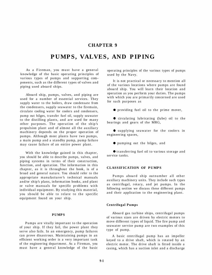
A basic centrifugal pump has an impellerkeyed to a drive shaft, which is rotated by anelectric motor. The drive shaft is fitted inside acasing, which has a suction inlet and a discharge
9-1
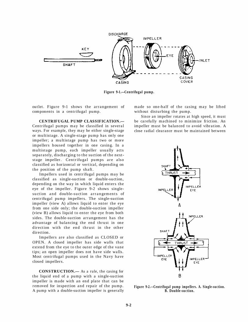
Figure 9-1.—Centrifugal pump.
outlet. Figure 9-1 shows the arrangement ofcomponents in a centrifugal pump.
CENTRIFUGAL PUMP CLASSIFICATION.—Centrifugal pumps may be classified in severalways. For example, they may be either single-stageor multistage. A single-stage pump has only oneimpeller; a multistage pump has two or moreimpellers housed together in one casing. In amultistage pump, each impeller usually actsseparately, discharging to the suction of the next-stage impeller. Centrifugal pumps are alsoclassified as horizontal or vertical, depending onthe position of the pump shaft.
Impellers used in centrifugal pumps may beclassified as single-suction or double-suction,depending on the way in which liquid enters theeye of the impeller. Figure 9-2 shows single-suction and double-suction arrangements ofcentrifugal pump impellers. The single-suctionimpeller (view A) allows liquid to enter the eyefrom one side only; the double-suction impeller(view B) allows liquid to enter the eye from bothsides. The double-suction arrangement has theadvantage of balancing the end thrust in onedirection with the end thrust in the otherdirection.
Impellers are also classified as CLOSED orOPEN. A closed impeller has side walls thatextend from the eye to the outer edge of the vanetips; an open impeller does not have side walls.Most centrifugal pumps used in the Navy haveclosed impellers.
CONSTRUCTION.— As a rule, the casing forthe liquid end of a pump with a single-suctionimpeller is made with an end plate that can beremoved for inspection and repair of the pump.A pump with a double-suction impeller is generally
made so one-half of the casing may be liftedwithout disturbing the pump.
Since an impeller rotates at high speed, it mustbe carefully machined to minimize friction. Animpeller must be balanced to avoid vibration. Aclose radial clearance must be maintained between
Figure 9-2.—Centrifugal pump impellers. A. Single-suction.B. Double-suction.
9-2
the outer hub of the impeller and that part ofthe pump casing in which the hub rotates. Thepurpose of this is to minimize leakage from thedischarge side of the pump casing to the suctionside.
Because of the high rotational speed of theimpeller and the necessarily close clearance, therubbing surfaces of both the impeller hub and thecasing at that point are subject to stress, causingrapid wear. To eliminate the need for replacingan entire impeller and pump casing solely becauseof wear in this location, most centrifugal pumpsare designed with replaceable casing wearing rings.
In most centrifugal pumps, the shaft is fittedwith a replaceable sleeve. The advantage ofusing a sleeve is that it can be replaced moreeconomically than the entire shaft.
Mechanical seals and stuffing boxes are usedto seal between the shaft and the casing. Mostpumps are now furnished with mechanical seals;mechanical seals do not result in better pumpoperation; but, they do provide a better environ-ment, keep bilges dry, and preserve the liquidbeing pumped.
Seal piping (liquid seal) is installed to cool themechanical seal. Most pumps in saltwater servicewith total head of 30 psi or more are also fittedwith cyclone separators. These separators usecentrifugal force to prevent abrasive material(such as sand in the seawater) from passingbetween the sealing surfaces of the mechanicalseal. There is an opening at each end of theseparator. The opening at the top is for “clean”water, which is directed though tubing to themechanical seals in the pump. The high-velocity“dirty” water is directed through the bottom ofthe separator, back to the inlet piping for thepump.
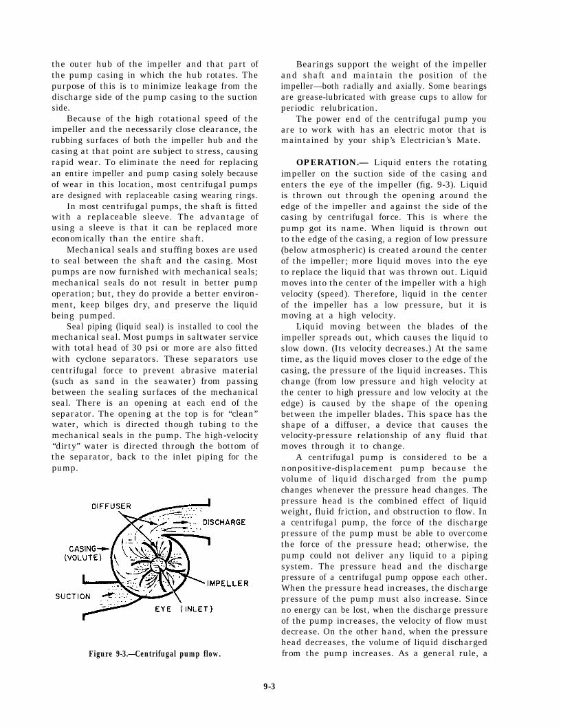
Figure 9-3.—Centrifugal pump flow.
Bearings support the weight of the impellerand shaft and maintain the position of theimpeller—both radially and axially. Some bearingsare grease-lubricated with grease cups to allow forperiodic relubrication.
The power end of the centrifugal pump youare to work with has an electric motor that ismaintained by your ship’s Electrician’s Mate.
OPERATION.— Liquid enters the rotatingimpeller on the suction side of the casing andenters the eye of the impeller (fig. 9-3). Liquidis thrown out through the opening around theedge of the impeller and against the side of thecasing by centrifugal force. This is where thepump got its name. When liquid is thrown outto the edge of the casing, a region of low pressure(below atmospheric) is created around the centerof the impeller; more liquid moves into the eyeto replace the liquid that was thrown out. Liquidmoves into the center of the impeller with a highvelocity (speed). Therefore, liquid in the centerof the impeller has a low pressure, but it ismoving at a high velocity.
Liquid moving between the blades of theimpeller spreads out, which causes the liquid toslow down. (Its velocity decreases.) At the sametime, as the liquid moves closer to the edge of thecasing, the pressure of the liquid increases. Thischange (from low pressure and high velocity atthe center to high pressure and low velocity at theedge) is caused by the shape of the openingbetween the impeller blades. This space has theshape of a diffuser, a device that causes thevelocity-pressure relationship of any fluid thatmoves through it to change.
A centrifugal pump is considered to be anonpositive-displacement pump because thevolume of liquid discharged from the pumpchanges whenever the pressure head changes. Thepressure head is the combined effect of liquidweight, fluid friction, and obstruction to flow. Ina centrifugal pump, the force of the dischargepressure of the pump must be able to overcomethe force of the pressure head; otherwise, thepump could not deliver any liquid to a pipingsystem. The pressure head and the dischargepressure of a centrifugal pump oppose each other.When the pressure head increases, the dischargepressure of the pump must also increase. Sinceno energy can be lost, when the discharge pressureof the pump increases, the velocity of flow mustdecrease. On the other hand, when the pressurehead decreases, the volume of liquid dischargedfrom the pump increases. As a general rule, a
9-3
Figure 9-4.—Nonpositive-displacement pump.
centrifugal pump is usually located below theliquid being pumped. (NOTE: This discussionassumes a constant impeller speed.)
Figure 9-4 shows that when the pump dis-charge is blocked, nothing happens because theimpeller is hollow. A tremendous buildup inpressure cannot occur because the passages in theimpeller (between the discharge and suction sideof the pump) act like a built-in relief valve. Whenthe discharge pressure and pressure head are equal(as in this case), the impeller is allowed to rotate(slips) through the liquid in the casing.
NOTE: Centrifugal pumps used for inter-mittent service may have to run for long periodsof time against a blocked discharge. Frictionbetween the impeller and the liquid raises thetemperature of the liquid in the casing and causesthe pump to overheat. To prevent this, a smallline is connected between the discharge and thesuction piping of the pump.
When a centrifugal pump is started, the ventline must be opened to release entrained air. Theopen passage through the impeller of a centrifugalpump also causes another problem. It’s possiblefor liquid to flow backwards (reverse flow)through the pump. A reverse flow, from thedischarge back to the suction, can happen whenthe pressure head overcomes the dischargepressure of the pump. A reverse flow can alsooccur when the pump isn’t running and anotherpump is delivering liquid to the same pipingsystem. To prevent a reverse flow of liquidthrough a centrifugal pump, a check valve isusually installed in the discharge line.
NOTE: Instead of two separate valves, someinstallations use a globe stop-check valve.
With a check valve in the discharge line,whenever the pressure above the disk rises abovethe pressure below it, the check valve shuts. Thisprevents liquid from flowing backwards throughthe pump.
MAINTENANCE.— You must observe theoperation and safety precautions pertaining topumps by following the EOP subsystem of theEOSS—if your ship has EOSS. If not, use theNaval Ships’ Technical Manual (NSTM) and/orthe instructions posted on or near each individualpump. You must follow the manufacturer’stechnical manual or MRCs for PMS-related workfor all maintenance work. The MRCs list in detailwhat you have to do for each individual mainte-nance requirement.
Mechanical Seals.— Mechanical seals arerapidly replacing conventional packing as themeans of controlling leakage on centrifugalpumps. Pumps fitted with mechanical sealseliminate the problem of excessive stuffing boxleakage, which can result in pump and motorbearing failures and motor winding failures.
Where mechanical shaft seals are used, thedesign ensures that positive liquid pressure issupplied to the seal faces under all conditions ofoperation and that there is adequate circulationof the liquid at the seal faces to minimize thedeposit of foreign matter on the seal parts.
One type of mechanical seal is shown in figure9-5. Spring pressure keeps the rotating seal face
Figure 9-5.—Type-1 mechanical seal.
9-4
Figure 9-6.—Stuffing box on a centrifugal pump.
snug against the stationary seal face. The rotatingseal and all of the assembly below it are affixedto the pump shaft. The stationary seal face is heldstationary by the seal gland and packing ring. Astatic seal is formed between the two seal facesand the sleeve. System pressure within the pumpassists the spring in keeping the rotating seal facetight against the stationary seal face. The type ofmaterial used for the seal face depends on theservice of the pump. When a seal wears out, itis simply replaced.
You should observe the following precautionswhen performing maintenance on mechanicalseals:
. Do not touch new seals on the sealing facebecause body acid and grease can cause the sealface to prematurely pit and fail.
. Replace mechanical seals when the seal isremoved for any reason or when the leakage ratecannot be tolerated.
. Position mechanical shaft seals on theshaft by stub or step sleeves. Shaft sleeves arechamfered (beveled) on outboard ends to provideease of mechanical seal mounting.
. Do not position mechanical shaft seals byusing setscrews.
Fire pumps and all seawater pumps installed insurface ships are being provided with mechanical
shaft seals with cyclone separators. The glands aredesigned to incorporate two or more rings ofpacking if the mechanical shaft seal fails.
A water flinger is fitted on the shaft outboardof the stuffing box glands to prevent leakage fromthe stuffing box following along the shaft andentering the bearing housings. They must fittightly on the shaft. If the flingers are fitted onthe shaft sleeves instead of on the shaft, ensurethat no water leaks under the sleeves.
Stuffing Box Packing.— Although mostcentrifugal pumps on gas turbine ships havemechanical seals, you should be familiar withstuffing box packing.
The packing in centrifugal pump stuffingboxes (fig. 9-6) is renewed following the PMS.When replacing packing, be sure to use packingof the specified material and the correct size.Stagger the joints in the packing rings so they fallat different points around the shaft. Pack thestuffing box loosely and set up lightly on thegland, allowing a liberal leakage. With the pumpin operation, tighten the glands and graduallycompress the packing. It is important to do thisgradually and evenly to avoid excessive friction.Uneven tightening could cause overheating andpossible scoring of the shaft or the shaft sleeve.
On some centrifugal pumps, a lantern ring isinserted between the rings of the packing. Whenrepacking stuffing boxes on such pumps, be sureto replace the packing beyond the lantern ring.
9-5
The packing should not block off the liquid sealline connection to the lantern ring after the glandhas been tightened.
Figure 9-6 shows how the packing is arranged.Notice how the lantern ring lines up with theliquid seal connection when the gland is tightened.
Renewing Shaft Sleeves.— In some pumps theshaft sleeve is pressed onto the shaft tightly bya hydraulic press. In this case, the old sleeve mustbe machined off with a lathe before a new onecan be installed. On others, the shaft sleeve mayhave a snug slip-on fit, butted up against ashoulder on the shaft and held securely in placewith a nut. On smaller pumps, new sleeves canbe installed by removing the water end casing,impeller, and old shaft sleeves. New sleeves arecarried as repair parts; they can also be made inthe machine shop. On a large pump, the sleeveis usually pressed on; the old sleeve must bemachined off before a new one can be pressed on.You must disassemble the pump and take thesleeve to a machine shop, a repair shop, or a navalshipyard to have this done.
To prevent water leakage between the shaftand the sleeve, some sleeves are packed, othershave an O-ring between the shaft and theabutting shoulder. For detailed information,consult the appropriate manufacturer’s technicalmanual or applicable blueprint.
Renewing Wearing Rings.— The clearancebetween the impeller and the casing wearing ring(fig. 9-7) must be maintained as directed bythe manufacturer. When clearances exceed thespecified amount, the casing wearing ring mustbe replaced. On most ships, this job can be done
by the ship’s force, but it requires the completedisassembly of the pump. All necessary informa-tion on disassembly of the unit, dimensions of thewearing rings, and reassembly of the pump isspecified by PMS or can be found in the manufac-turer’s technical manual. Failure to replace thecasing wearing ring when the allowable clearanceis exceeded results in a decrease of pump capacityand efficiency. If a pump has to be disassembledbecause of some internal trouble, the wearing ringshould be checked for clearance. Measure theoutside diameter of the impeller hub with anoutside micrometer and the inside diameter of thecasing wearing ring with an inside micrometer; thedifference between the two diameters is theactual wearing ring diametric clearance. Bychecking the actual wearing ring clearance withthe maximum allowable clearance, you can decidewhether to renew the ring before reassembling thepump. The applicable MRCs area readily availablesource of information on proper clearances.
Wearing rings for most small pumps arecarried aboard ship as part of the ship’s repairparts allowance. These may need only a slightamount of machining before they can be installed.For some pumps, spare rotors are carried aboardship. The new rotor can be installed and the oldrotor sent to a repair activity for overhaul.Overhauling a rotor includes renewing thewearing rings, bearings, and shaft sleeve.
Operating Troubles.— You will be responsiblefor the maintenance of centrifugal pumps. Thefollowing table is a description of some of theproblems you will have to deal with together withthe probable causes:
TROUBLE CAUSE
Does not deliver any Insufficient primingliquid Insufficient speed of the
pump
Excessive discharge pressure(such as a partially closedvalve or some other obstruc-tion in the discharge line)
Excessive suction lift
Clogged impeller passages
Wrong direction of rotation
Clogged suction screen (ifused)
Figure 9-7.—Impeller, impeller wearing ring, and casingwearing ring for a centrifugal pump.
Ruptured suction line
Loss of suction pressure
9-6
TROUBLE
Insufficient capacity
Does not develop enoughdischarge pressure
Works for a while andthen fails to deliverliquid
Takes too much powerand the motor overheats
CAUSE
Air leakage into the suctionline
Insufficient speed of thepump
Excessive suction lift
Clogged impeller passages
Excessive discharge pressure
Mechanical defects (such asworn wearing rings, im-pellers, stuffing box pack-ing, or sleeves)
Insufficient speed of thepump
Air or gas in the liquid beingpumped
Mechanical defects (such asworn wearing rings, im-pellers, leaking mechanicalseals, and sleeves)
Air leakage into the suctionline
Air leakage in the stuffingboxes
Clogged water seal passages
Insufficient liquid on thesuction side
Excessive heat in the liquidbeing pumped
Operation of the pump atexcess capacity and insuffi-cient discharge pressure
Misalignment
Bent shaft
Excessively tight stuffingbox packing
Worn
Other
wearing rings
mechanical defects
TROUBLE CAUSE
Vibration Misalignment
Bent shaft
Clogged, eroded, or other-wise unbalanced impeller
Lack of rigidity in thefoundation
Insufficient suction pressure may also causevibration, as well as noisy operation andfluctuating discharge pressure.
Rotary Pumps
Another type of pump you find aboard shipis the rotary pump. A number of types areincluded in this classification, among which arethe gear pump, the screw pump, and the movingvane pump. Unlike the centrifugal pump, whichwe have discussed, the rotary pump is a positive-displacement pump. This means that for eachrevolution of the pump, a fixed volume of fluidis moved regardless of the resistance against whichthe pump is pushing. As you can see, any blockagein the system could quickly cause damage to thepump or a rupture of the system. You, as a pumpoperator, must always be sure that the system isproperly aligned so a complete flow path existsfor fluid flow. Also, because of their positivedisplacement feature, rotary pumps require arelief valve to protect the pump and piping system.The relief valve lifts at a preset pressure andreturns the system liquid either to the suction sideof the pump or back to the supply tank or sump.
Rotary pumps are also different fromcentrifugal pumps in that they are essentiallyself-priming. As we saw in our discussion ofcentrifugal pumps, the pump is located below theliquid being pumped; gravity creates a staticpressure head which keeps the pump primed. Arotary pump operates within limits with the pumplocated above the source of supply.
A good example of the principle that makesrotary pumps self-priming is the simple drinkingstraw. As you suck on the straw, you lower theair pressure inside the straw. Atmosphericpressure on the surface of the liquid surroundingthe straw is therefore greater and forces the liquidup the straw. The same conditions basically existfor the gear and screw pump to prime itself.
9-7
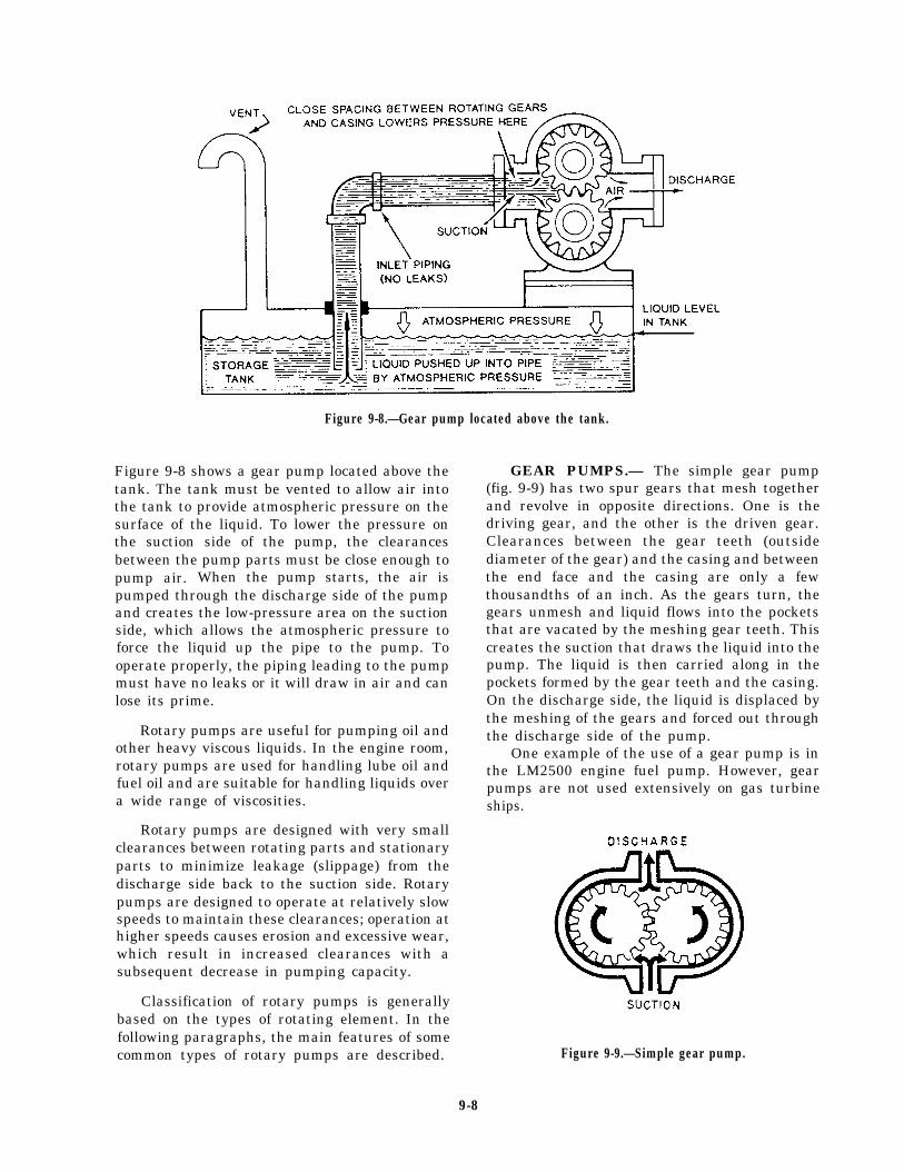
Figure 9-8.—Gear pump located above the tank.
Figure 9-8 shows a gear pump located above thetank. The tank must be vented to allow air intothe tank to provide atmospheric pressure on thesurface of the liquid. To lower the pressure onthe suction side of the pump, the clearancesbetween the pump parts must be close enough topump air. When the pump starts, the air ispumped through the discharge side of the pumpand creates the low-pressure area on the suctionside, which allows the atmospheric pressure toforce the liquid up the pipe to the pump. Tooperate properly, the piping leading to the pumpmust have no leaks or it will draw in air and canlose its prime.
Rotary pumps are useful for pumping oil andother heavy viscous liquids. In the engine room,rotary pumps are used for handling lube oil andfuel oil and are suitable for handling liquids overa wide range of viscosities.
Rotary pumps are designed with very smallclearances between rotating parts and stationaryparts to minimize leakage (slippage) from thedischarge side back to the suction side. Rotarypumps are designed to operate at relatively slowspeeds to maintain these clearances; operation athigher speeds causes erosion and excessive wear,which result in increased clearances with asubsequent decrease in pumping capacity.
Classification of rotary pumps is generallybased on the types of rotating element. In thefollowing paragraphs, the main features of somecommon types of rotary pumps are described.
GEAR PUMPS.— The simple gear pump(fig. 9-9) has two spur gears that mesh togetherand revolve in opposite directions. One is thedriving gear, and the other is the driven gear.Clearances between the gear teeth (outsidediameter of the gear) and the casing and betweenthe end face and the casing are only a fewthousandths of an inch. As the gears turn, thegears unmesh and liquid flows into the pocketsthat are vacated by the meshing gear teeth. Thiscreates the suction that draws the liquid into thepump. The liquid is then carried along in thepockets formed by the gear teeth and the casing.On the discharge side, the liquid is displaced bythe meshing of the gears and forced out throughthe discharge side of the pump.
One example of the use of a gear pump is inthe LM2500 engine fuel pump. However, gearpumps are not used extensively on gas turbineships.
Figure 9-9.—Simple gear pump.
9-8
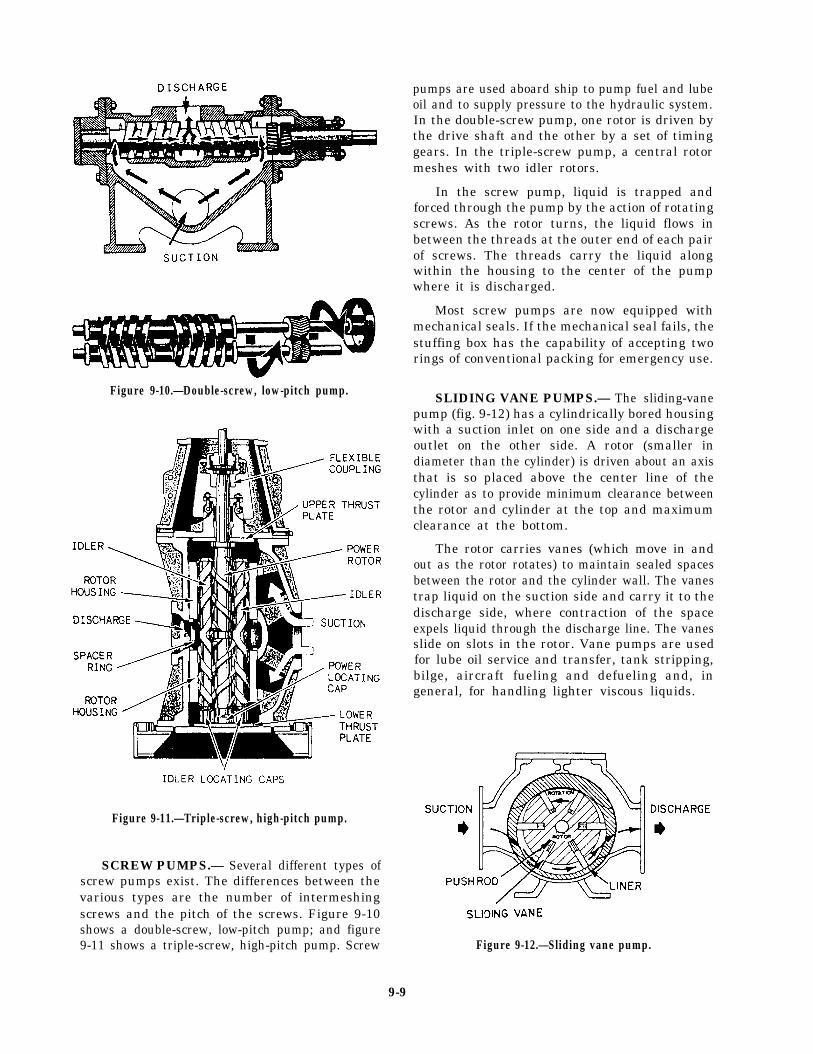
pumps are used aboard ship to pump fuel and lubeoil and to supply pressure to the hydraulic system.In the double-screw pump, one rotor is driven bythe drive shaft and the other by a set of timinggears. In the triple-screw pump, a central rotormeshes with two idler rotors.
In the screw pump, liquid is trapped andforced through the pump by the action of rotatingscrews. As the rotor turns, the liquid flows inbetween the threads at the outer end of each pairof screws. The threads carry the liquid alongwithin the housing to the center of the pumpwhere it is discharged.
Most screw pumps are now equipped withmechanical seals. If the mechanical seal fails, thestuffing box has the capability of accepting tworings of conventional packing for emergency use.
Figure 9-10.—Double-screw, low-pitch pump.
Figure 9-11.—Triple-screw, high-pitch pump.
SCREW PUMPS.— Several different types ofscrew pumps exist. The differences between thevarious types are the number of intermeshingscrews and the pitch of the screws. Figure 9-10shows a double-screw, low-pitch pump; and figure9-11 shows a triple-screw, high-pitch pump. Screw
SLIDING VANE PUMPS.— The sliding-vanepump (fig. 9-12) has a cylindrically bored housingwith a suction inlet on one side and a dischargeoutlet on the other side. A rotor (smaller indiameter than the cylinder) is driven about an axisthat is so placed above the center line of thecylinder as to provide minimum clearance betweenthe rotor and cylinder at the top and maximumclearance at the bottom.
The rotor carries vanes (which move in andout as the rotor rotates) to maintain sealed spacesbetween the rotor and the cylinder wall. The vanestrap liquid on the suction side and carry it to thedischarge side, where contraction of the spaceexpels liquid through the discharge line. The vanesslide on slots in the rotor. Vane pumps are usedfor lube oil service and transfer, tank stripping,bilge, aircraft fueling and defueling and, ingeneral, for handling lighter viscous liquids.
Figure 9-12.—Sliding vane pump.
9-9
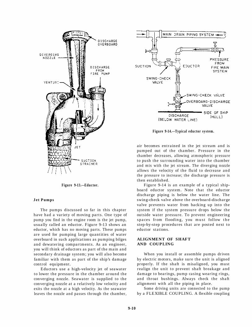
Figure 9-13.—Eductor.
Jet Pumps
The pumps discussed so far in this chapterhave had a variety of moving parts. One type ofpump you find in the engine room is the jet pump,usually called an eductor. Figure 9-13 shows aneductor, which has no moving parts. These pumpsare used for pumping large quantities of wateroverboard in such applications as pumping bilgesand dewatering compartments. As an engineer,you will think of eductors as part of the main andsecondary drainage system; you will also becomefamiliar with them as part of the ship’s damagecontrol equipment.
Eductors use a high-velocity jet of seawaterto lower the pressure in the chamber around theconverging nozzle. Seawater is supplied to theconverging nozzle at a relatively low velocity andexits the nozzle at a high velocity. As the seawaterleaves the nozzle and passes through the chamber,
Figure 9-14.—Typical eductor system.
air becomes entrained in the jet stream and ispumped out of the chamber. Pressure in thechamber decreases, allowing atmospheric pressureto push the surrounding water into the chamberand mix with the jet stream. The diverging nozzleallows the velocity of the fluid to decrease andthe pressure to increase; the discharge pressure isthen established.
Figure 9-14 is an example of a typical ship-board eductor system. Note that the eductordischarge piping is below the water line. Theswing-check valve above the overboard-dischargevalve prevents water from backing up into thesystem if the system pressure drops below theoutside water pressure. To prevent engineeringspaces from flooding, you must follow thestep-by-step procedures that are posted next toeductor stations.
ALIGNMENT OF SHAFTAND COUPLING
When you install or assemble pumps drivenby electric motors, make sure the unit is alignedproperly. If the shaft is misaligned, you mustrealign the unit to prevent shaft breakage anddamage to bearings, pump casing wearing rings,and throat bushings. Always check the shaftalignment with all the piping in place.
Some driving units are connected to the pumpby a FLEXIBLE COUPLING. A flexible coupling
9-10
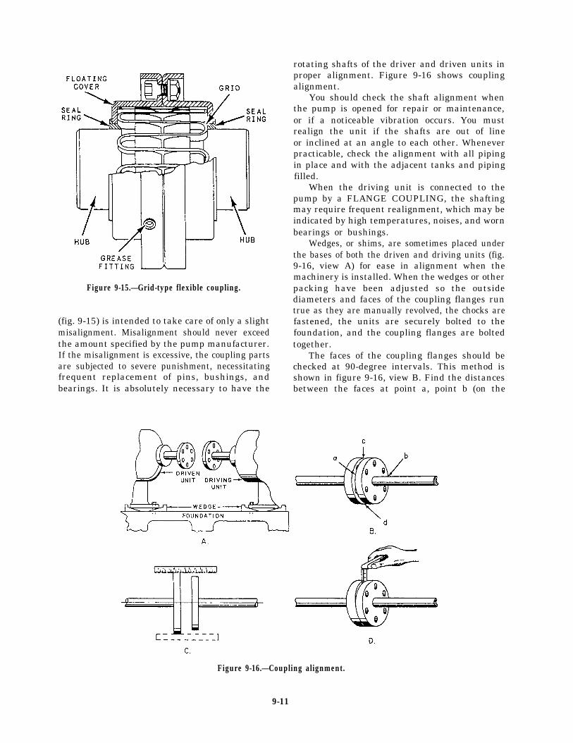
Figure 9-15.—Grid-type flexible coupling.
(fig. 9-15) is intended to take care of only a slightmisalignment. Misalignment should never exceedthe amount specified by the pump manufacturer.If the misalignment is excessive, the coupling partsare subjected to severe punishment, necessitatingfrequent replacement of pins, bushings, andbearings. It is absolutely necessary to have the
rotating shafts of the driver and driven units inproper alignment. Figure 9-16 shows couplingalignment.
You should check the shaft alignment whenthe pump is opened for repair or maintenance,or if a noticeable vibration occurs. You mustrealign the unit if the shafts are out of lineor inclined at an angle to each other. Wheneverpracticable, check the alignment with all pipingin place and with the adjacent tanks and pipingfilled.
When the driving unit is connected to thepump by a FLANGE COUPLING, the shaftingmay require frequent realignment, which may beindicated by high temperatures, noises, and wornbearings or bushings.
Wedges, or shims, are sometimes placed underthe bases of both the driven and driving units (fig.9-16, view A) for ease in alignment when themachinery is installed. When the wedges or otherpacking have been adjusted so the outsidediameters and faces of the coupling flanges runtrue as they are manually revolved, the chocks arefastened, the units are securely bolted to thefoundation, and the coupling flanges are boltedtogether.
The faces of the coupling flanges should bechecked at 90-degree intervals. This method isshown in figure 9-16, view B. Find the distancesbetween the faces at point a, point b (on the
Figure 9-16.—Coupling alignment.
9-11
opposite side), point c, and point d (opposite pointc). This action will show whether the couplingfaces are parallel to each other. If they are notparallel to each other, adjust the driving unit orthe pump with shims until the couplings checktrue. While measuring the distances, you mustkeep the outside diameters of the coupling flangesin line. To do this, place the scale across the twoflanges, as shown in figure 9-16, view C. If theflanges do not line up, raise or lower one of theunits with shims, or shift them sideways.
The procedure for using a thickness gauge tocheck alignments is similar to that for a scale.When the outside diameters of the couplingflanges are not the same, use a scale on the
surface of the larger flange, and then use athickness gauge between the surface of the smallerflange and the edge of the scale. When the spaceis narrow, check the distance between the couplingflanges with a thickness gauge, as shown in figure9-16, view D. Check wider spaces with a piece ofsquare key stock and a thickness gauge.
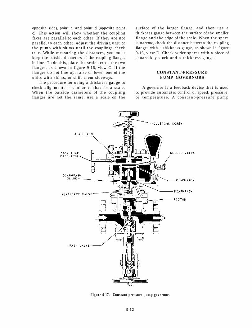
CONSTANT-PRESSUREPUMP GOVERNORS
A governor is a feedback device that is usedto provide automatic control of speed, pressure,or temperature. A constant-pressure pump
Figure 9-17.—Constant-pressure pump governor.
9-12
governor maintains a constant discharge pressure,regardless of pump capacity or output. Mostconstant-pressure pump governors used in theNavy control steam-driven pumps, both rotaryand centrifugal types.
The constant-pressure pump governor (some-times referred to as pressure-regulating) consistsessentially of an automatic throttling valveinstalled in the steam supply line to the pump’sdriving unit. A pipeline connects the governor tothe pump’s discharge line. Variations in dischargepressure, or in pressure differential, actuatethe governor, causing it to regulate the pumpspeed by varying the flow of steam to the drivingunit.
A constant-pressure pump governor for alubricating oil service pump is shown in figure9-17. The governors used on fuel oil servicepumps and on main feed pumps are of the sametype. The size of the upper diaphragm and theamount of spring tension vary on governorsused for different services. You will finddetailed information concerning the operation andadjustment of governors in chapter 503 of theNSTM.
VALVES
A valve is any device used to control fluidsin a closed system. In this section we will discussvalve construction and the most common typesof valves you will use in the day-to-day operationand maintenance of the various shipboardengineering systems. Valves are typed or classifiedaccording to their use in a system.
VALVE CONSTRUCTION
Valves are usually made of bronze, brass,cast or malleable iron, or steel. Steel valvesare either cast or forged and are made of eitherplain steel or alloy steel. Alloy steel valves areused in high-pressure, high-temperature systems;the disks and seats (internal sealing surfaces) ofthese valves are usually surfaced with a chromium-cobalt alloy known as Stellite. Stellite is extremelyhard.
Brass and bronze valves are never used insystems where temperatures exceed 550°F. Steel
valves are used for all services above 550°F andin lower temperature systems where internal orexternal conditions of high pressure, vibration,or shock would be too severe for valves madeof brass or bronze. Bronze valves are usedalmost exclusively in systems that carry saltwater. The seats and disks of these valvesare usually made of Monel, a metal thathas excellent corrosion- and erosion-resistantqualities.
Most submarine seawater valves are made ofan alloy of 70 percent copper to 30 percent nickel(70/30).
VALVE TYPES
Although many different types of valves areused to control the flow of fluids, the basic valvetypes can be divided into two general groups: stopvalves and check valves.
Besides the basic types of valves, manyspecial valves, which cannot really be classifiedas either stop valves or check valves, arefound in the engineering spaces. Many of thesevalves serve to control the pressure of fluidsand are known as pressure-control valves. Othervalves are identified by names that indicatetheir general function, such as thermostaticrecirculating valves. The following sectionsdeal first with the basic types of stop valvesand check valves, then with some of the morecomplicated special valves.
Stop Valves
Stop valves are used to shut off or, insome cases, partially shut off the flow of fluid.Stop valves are controlled by the movement ofthe valve stem. Stop valves can be divided intofour general categories: globe, gate, butterfly, andball valves. Plug valves and needle valves may alsobe considered stop valves.
GLOBE VALVES.— Globe valves are probablythe most common valves in existence. The globevalve derives its name from the globular shape ofthe valve body. However, positive identificationof a globe valve must be made internally becauseother valve types may have globular appearingbodies. Globe valve inlet and outlet openingsare arranged in several ways to suit varying
9-13
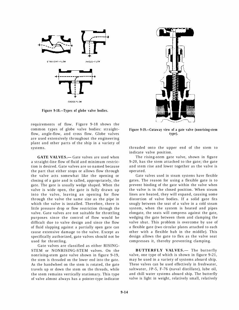
Figure 9-18.—Types of globe valve bodies.
requirements of flow. Figure 9-18 shows thecommon types of globe valve bodies: straight-flow, angle-flow, and cross flow. Globe valvesare used extensively throughout the engineeringplant and other parts of the ship in a variety ofsystems.
GATE VALVES.— Gate valves are used whena straight-line flow of fluid and minimum restric-tion is desired. Gate valves are so named becausethe part that either stops or allows flow throughthe valve acts somewhat like the opening orclosing of a gate and is called, appropriately, thegate. The gate is usually wedge shaped. When thevalve is wide open, the gate is fully drawn upinto the valve, leaving an opening for flowthrough the valve the same size as the pipe inwhich the valve is installed. Therefore, there islittle pressure drop or flow restriction through thevalve. Gate valves are not suitable for throttlingpurposes since the control of flow would bedifficult due to valve design and since the flowof fluid slapping against a partially open gate cancause extensive damage to the valve. Except asspecifically authorized, gate valves should not beused for throttling.
Gate valves are classified as either RISING-STEM or NONRISING-STEM valves. On thenonrising-stem gate valve shown in figure 9-19,the stem is threaded on the lower end into the gate.As the handwheel on the stem is rotated, the gatetravels up or down the stem on the threads, whilethe stem remains vertically stationary. This typeof valve almost always has a pointer-type indicator
Figure 9-19.—Cutaway view of a gate valve (nonrising-stemtype).
threaded onto the upper end of the stem toindicate valve position.
The rising-stem gate valve, shown in figure9-20, has the stem attached to the gate; the gateand stem rise and lower together as the valve isoperated.
Gate valves used in steam systems have flexiblegates. The reason for using a flexible gate is toprevent binding of the gate within the valve whenthe valve is in the closed position. When steamlines are heated, they will expand, causing somedistortion of valve bodies. If a solid gate fitssnugly between the seat of a valve in a cold steamsystem, when the system is heated and pipeselongate, the seats will compress against the gate,wedging the gate between them and clamping thevalve shut. This problem is overcome by use ofa flexible gate (two circular plates attached to eachother with a flexible hub in the middle). Thisdesign allows the gate to flex as the valve seatcompresses it, thereby preventing clamping.
BUTTERFLY VALVES.— The butterflyvalve, one type of which is shown in figure 9-21,may be used in a variety of systems aboard ship.These valves can be used effectively in freshwater,saltwater, JP-5, F-76 (naval distillate), lube oil,and chill water systems aboard ship. The butterflyvalve is light in weight, relatively small, relatively
9-14
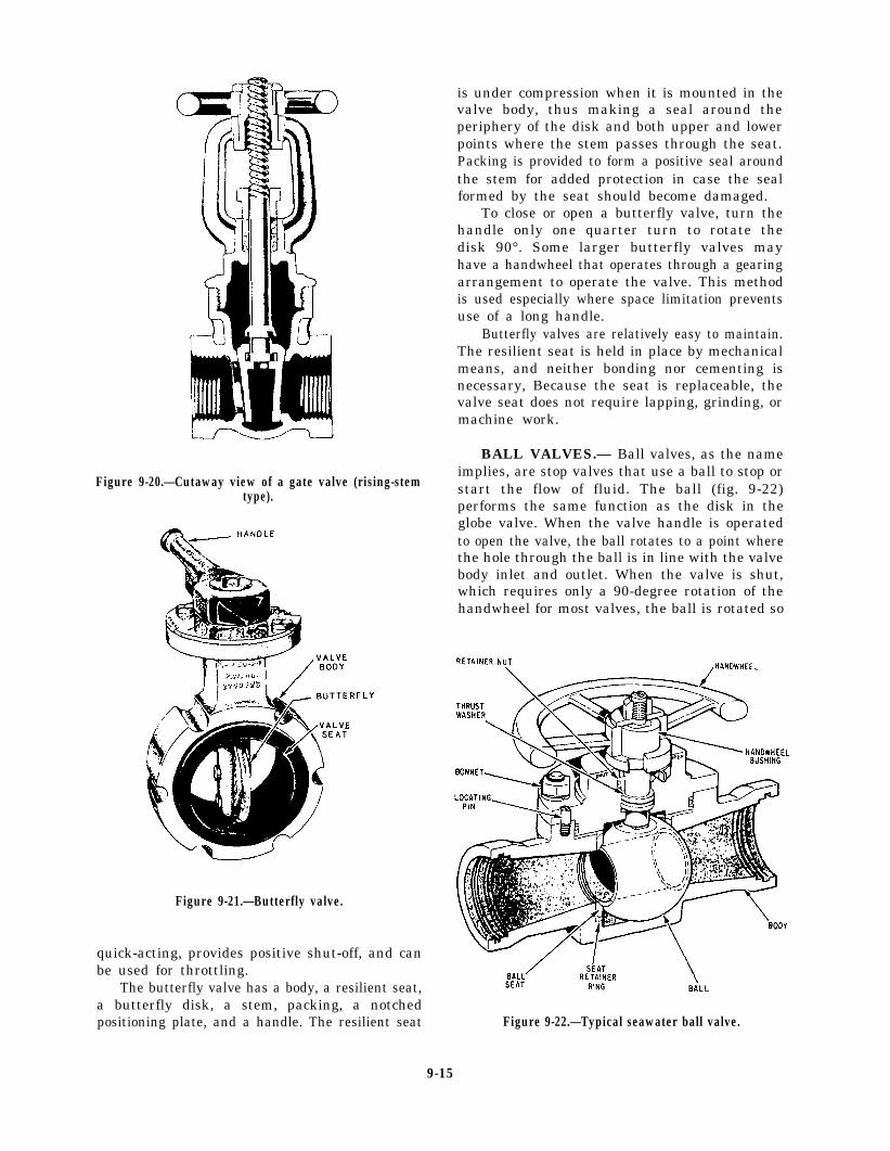
Figure 9-20.—Cutaway view of a gate valve (rising-stemtype).
Figure 9-21.—Butterfly valve.
quick-acting, provides positive shut-off, and canbe used for throttling.
The butterfly valve has a body, a resilient seat,a butterfly disk, a stem, packing, a notchedpositioning plate, and a handle. The resilient seat
is under compression when it is mounted in thevalve body, thus making a seal around theperiphery of the disk and both upper and lowerpoints where the stem passes through the seat.Packing is provided to form a positive seal aroundthe stem for added protection in case the sealformed by the seat should become damaged.
To close or open a butterfly valve, turn thehandle only one quarter turn to rotate thedisk 90°. Some larger butterfly valves mayhave a handwheel that operates through a gearingarrangement to operate the valve. This methodis used especially where space limitation preventsuse of a long handle.
Butterfly valves are relatively easy to maintain.The resilient seat is held in place by mechanicalmeans, and neither bonding nor cementing isnecessary, Because the seat is replaceable, thevalve seat does not require lapping, grinding, ormachine work.
BALL VALVES.— Ball valves, as the nameimplies, are stop valves that use a ball to stop orstart the flow of fluid. The ball (fig. 9-22)performs the same function as the disk in theglobe valve. When the valve handle is operatedto open the valve, the ball rotates to a point wherethe hole through the ball is in line with the valvebody inlet and outlet. When the valve is shut,which requires only a 90-degree rotation of thehandwheel for most valves, the ball is rotated so
Figure 9-22.—Typical seawater ball valve.
9-15
the hole is perpendicular to the flow openings ofthe valve body, and flow is stopped.
Most ball valves are of the quick-acting type(requiring only a 90-degree turn to operate thevalve either completely open or closed), but manyare planetary gear operated. This type of gearingallows the use of a relatively small handwheel andoperating force to operate a fairly large valve. Thegearing does, however, increase the operating timefor the valve. Some ball valves contain a swingcheck located within the ball to give the valve acheck valve feature. Ball valves are normallyfound in the following systems aboard ship:seawater, sanitary, trim and drain, air, hydraulic,and oil transfer.
Check Valves
Check valves are used to allow fluid flow ina system in only one direction. They are operatedby the flow of fluid in the piping. A check valvemay be the swing type, lift type, or ball type.
As we have seen, most valves can be classifiedas being either stop valves or check valves. Some
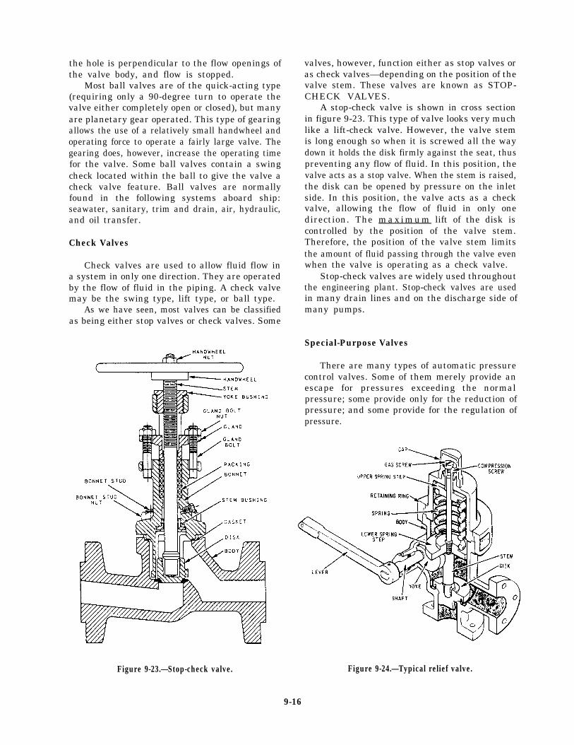
valves, however, function either as stop valves oras check valves—depending on the position of thevalve stem. These valves are known as STOP-CHECK VALVES.
A stop-check valve is shown in cross sectionin figure 9-23. This type of valve looks very muchlike a lift-check valve. However, the valve stemis long enough so when it is screwed all the waydown it holds the disk firmly against the seat, thuspreventing any flow of fluid. In this position, thevalve acts as a stop valve. When the stem is raised,the disk can be opened by pressure on the inletside. In this position, the valve acts as a checkvalve, allowing the flow of fluid in only onedirection. The m a x i m u m lift of the disk iscontrolled by the position of the valve stem.Therefore, the position of the valve stem limitsthe amount of fluid passing through the valve evenwhen the valve is operating as a check valve.
Stop-check valves are widely used throughoutthe engineering plant. Stop-check valves are usedin many drain lines and on the discharge side ofmany pumps.
Special-Purpose Valves
There are many types of automatic pressurecontrol valves. Some of them merely provide anescape for pressures exceeding the normalpressure; some provide only for the reduction ofpressure; and some provide for the regulation ofpressure.
Figure 9-23.—Stop-check valve. Figure 9-24.—Typical relief valve.
9-16
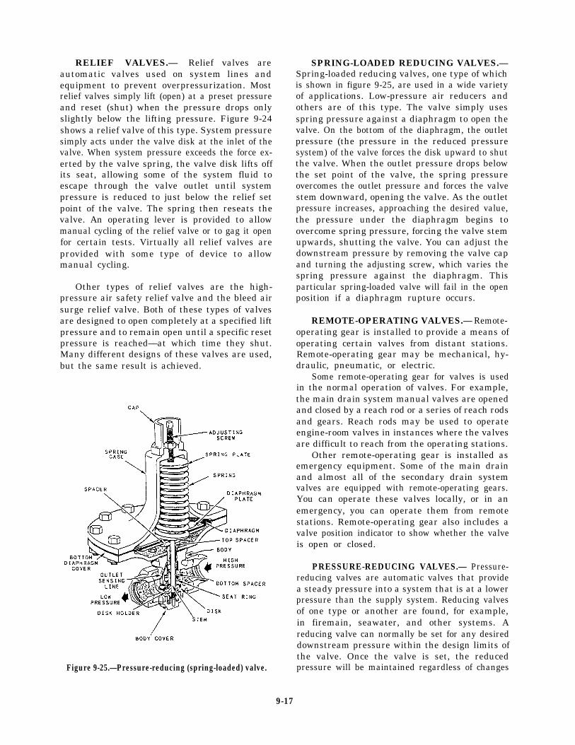
RELIEF VALVES.— Relief valves areautomatic valves used on system lines andequipment to prevent overpressurization. Mostrelief valves simply lift (open) at a preset pressureand reset (shut) when the pressure drops onlyslightly below the lifting pressure. Figure 9-24shows a relief valve of this type. System pressuresimply acts under the valve disk at the inlet of thevalve. When system pressure exceeds the force ex-erted by the valve spring, the valve disk lifts offits seat, allowing some of the system fluid toescape through the valve outlet until systempressure is reduced to just below the relief setpoint of the valve. The spring then reseats thevalve. An operating lever is provided to allowmanual cycling of the relief valve or to gag it openfor certain tests. Virtually all relief valves areprovided with some type of device to allowmanual cycling.
Other types of relief valves are the high-pressure air safety relief valve and the bleed airsurge relief valve. Both of these types of valvesare designed to open completely at a specified liftpressure and to remain open until a specific resetpressure is reached—at which time they shut.Many different designs of these valves are used,but the same result is achieved.
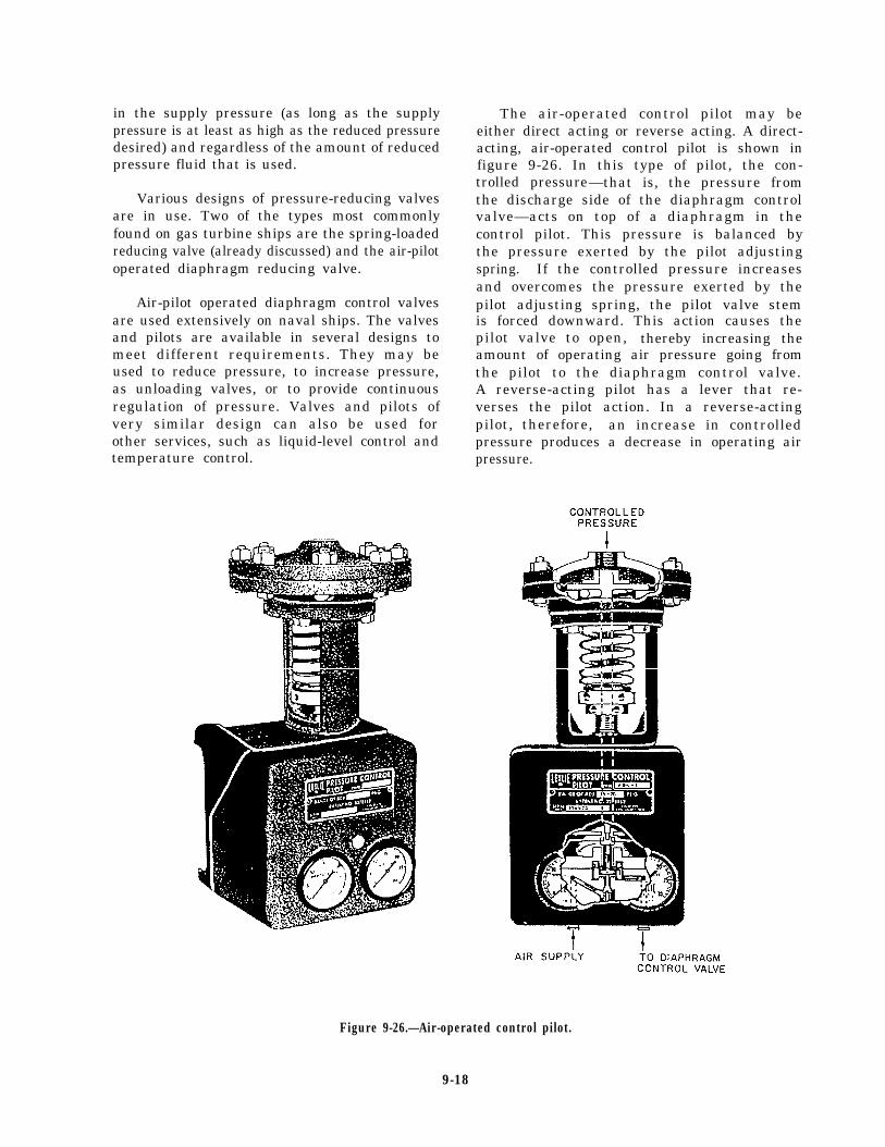
Figure 9-25.—Pressure-reducing (spring-loaded) valve.
SPRING-LOADED REDUCING VALVES.—Spring-loaded reducing valves, one type of whichis shown in figure 9-25, are used in a wide varietyof applications. Low-pressure air reducers andothers are of this type. The valve simply usesspring pressure against a diaphragm to open thevalve. On the bottom of the diaphragm, the outletpressure (the pressure in the reduced pressuresystem) of the valve forces the disk upward to shutthe valve. When the outlet pressure drops belowthe set point of the valve, the spring pressureovercomes the outlet pressure and forces the valvestem downward, opening the valve. As the outletpressure increases, approaching the desired value,the pressure under the diaphragm begins toovercome spring pressure, forcing the valve stemupwards, shutting the valve. You can adjust thedownstream pressure by removing the valve capand turning the adjusting screw, which varies thespring pressure against the diaphragm. Thisparticular spring-loaded valve will fail in the openposition if a diaphragm rupture occurs.
REMOTE-OPERATING VALVES.— Remote-operating gear is installed to provide a means ofoperating certain valves from distant stations.Remote-operating gear may be mechanical, hy-draulic, pneumatic, or electric.
Some remote-operating gear for valves is usedin the normal operation of valves. For example,the main drain system manual valves are openedand closed by a reach rod or a series of reach rodsand gears. Reach rods may be used to operateengine-room valves in instances where the valvesare difficult to reach from the operating stations.
Other remote-operating gear is installed asemergency equipment. Some of the main drainand almost all of the secondary drain systemvalves are equipped with remote-operating gears.You can operate these valves locally, or in anemergency, you can operate them from remotestations. Remote-operating gear also includes avalve position indicator to show whether the valveis open or closed.
PRESSURE-REDUCING VALVES.— Pressure-reducing valves are automatic valves that providea steady pressure into a system that is at a lowerpressure than the supply system. Reducing valvesof one type or another are found, for example,in firemain, seawater, and other systems. Areducing valve can normally be set for any desireddownstream pressure within the design limits ofthe valve. Once the valve is set, the reducedpressure will be maintained regardless of changes
9-17
in the supply pressure (as long as the supplypressure is at least as high as the reduced pressuredesired) and regardless of the amount of reducedpressure fluid that is used.
Various designs of pressure-reducing valvesare in use. Two of the types most commonlyfound on gas turbine ships are the spring-loadedreducing valve (already discussed) and the air-pilotoperated diaphragm reducing valve.
Air-pilot operated diaphragm control valvesare used extensively on naval ships. The valvesand pilots are available in several designs tomeet different requirements. They may beused to reduce pressure, to increase pressure,as unloading valves, or to provide continuousregulation of pressure. Valves and pilots ofvery similar design can also be used forother services, such as liquid-level control andtemperature control.
The air-operated control pilot may beeither direct acting or reverse acting. A direct-acting, air-operated control pilot is shown infigure 9-26. In this type of pilot, the con-trolled pressure—that is, the pressure fromthe discharge side of the diaphragm controlvalve—acts on top of a diaphragm in thecontrol pilot. This pressure is balanced bythe pressure exerted by the pilot adjustingspring. If the controlled pressure increasesand overcomes the pressure exerted by thepilot adjusting spring, the pilot valve stemis forced downward. This action causes thepilot valve to open, thereby increasing theamount of operating air pressure going fromthe pilot to the diaphragm control valve.A reverse-acting pilot has a lever that re-verses the pilot action. In a reverse-actingpilot, therefore, an increase in controlledpressure produces a decrease in operating airpressure.
Figure 9-26.—Air-operated control pilot.
9-18
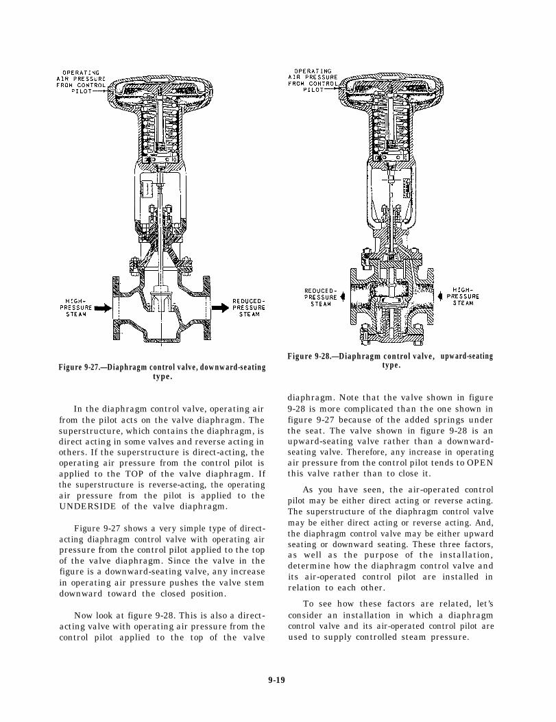
Figure 9-27.—Diaphragm control valve, downward-seatingtype.
In the diaphragm control valve, operating airfrom the pilot acts on the valve diaphragm. Thesuperstructure, which contains the diaphragm, isdirect acting in some valves and reverse acting inothers. If the superstructure is direct-acting, theoperating air pressure from the control pilot isapplied to the TOP of the valve diaphragm. Ifthe superstructure is reverse-acting, the operatingair pressure from the pilot is applied to theUNDERSIDE of the valve diaphragm.
Figure 9-27 shows a very simple type of direct-acting diaphragm control valve with operating airpressure from the control pilot applied to the topof the valve diaphragm. Since the valve in thefigure is a downward-seating valve, any increasein operating air pressure pushes the valve stemdownward toward the closed position.
Now look at figure 9-28. This is also a direct-acting valve with operating air pressure from thecontrol pilot applied to the top of the valve
Figure 9-28.—Diaphragm control valve,type.
upward-seating
diaphragm. Note that the valve shown in figure9-28 is more complicated than the one shown infigure 9-27 because of the added springs underthe seat. The valve shown in figure 9-28 is anupward-seating valve rather than a downward-seating valve. Therefore, any increase in operatingair pressure from the control pilot tends to OPENthis valve rather than to close it.
As you have seen, the air-operated controlpilot may be either direct acting or reverse acting.The superstructure of the diaphragm control valvemay be either direct acting or reverse acting. And,the diaphragm control valve may be either upwardseating or downward seating. These three factors,as well as the purpose of the installation,determine how the diaphragm control valve andits air-operated control pilot are installed inrelation to each other.
To see how these factors are related, let’sconsider an installation in which a diaphragmcontrol valve and its air-operated control pilot areused to supply controlled steam pressure.
9-19
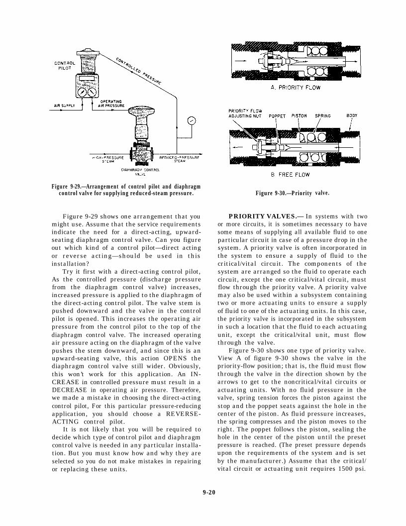
Figure 9-29.—Arrangement of control pilot and diaphragmcontrol valve for supplying reduced-steam pressure.
Figure 9-29 shows one arrangement that youmight use. Assume that the service requirementsindicate the need for a direct-acting, upward-seating diaphragm control valve. Can you figureout which kind of a control pilot—direct actingor reverse acting—should be used in thisinstallation?
Try it first with a direct-acting control pilot,As the controlled pressure (discharge pressurefrom the diaphragm control valve) increases,increased pressure is applied to the diaphragm ofthe direct-acting control pilot. The valve stem ispushed downward and the valve in the controlpilot is opened. This increases the operating airpressure from the control pilot to the top of thediaphragm control valve. The increased operatingair pressure acting on the diaphragm of the valvepushes the stem downward, and since this is anupward-seating valve, this action OPENS thediaphragm control valve still wider. Obviously,this won’t work for this application. An IN-CREASE in controlled pressure must result in aDECREASE in operating air pressure. Therefore,we made a mistake in choosing the direct-actingcontrol pilot, For this particular pressure-reducingapplication, you should choose a REVERSE-ACTING control pilot.
It is not likely that you will be required todecide which type of control pilot and diaphragmcontrol valve is needed in any particular installa-tion. But you must know how and why they areselected so you do not make mistakes in repairingor replacing these units.
Figure 9-30.—Priority
PRIORITY VALVES.— In
valve.
systems with twoor more circuits, it is sometimes necessary to havesome means of supplying all available fluid to oneparticular circuit in case of a pressure drop in thesystem. A priority valve is often incorporated inthe system to ensure a supply of fluid to thecritical/vital circuit. The components of thesystem are arranged so the fluid to operate eachcircuit, except the one critical/vital circuit, mustflow through the priority valve. A priority valvemay also be used within a subsystem containingtwo or more actuating units to ensure a supplyof fluid to one of the actuating units. In this case,the priority valve is incorporated in the subsystemin such a location that the fluid to each actuatingunit, except the critical/vital unit, must flowthrough the valve.
Figure 9-30 shows one type of priority valve.View A of figure 9-30 shows the valve in thepriority-flow position; that is, the fluid must flowthrough the valve in the direction shown by thearrows to get to the noncritical/vital circuits oractuating units. With no fluid pressure in thevalve, spring tension forces the piston against thestop and the poppet seats against the hole in thecenter of the piston. As fluid pressure increases,the spring compresses and the piston moves to theright. The poppet follows the piston, sealing thehole in the center of the piston until the presetpressure is reached. (The preset pressure dependsupon the requirements of the system and is setby the manufacturer.) Assume that the critical/vital circuit or actuating unit requires 1500 psi.
9-20
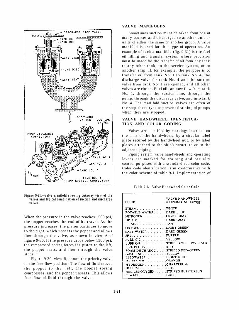
Figure 9-31.—Valve manifold showing cutaway view of thevalves and typical combination of suction and dischargevalves.
When the pressure in the valve reaches 1500 psi,the poppet reaches the end of its travel. As thepressure increases, the piston continues to moveto the right, which unseats the poppet and allowsflow through the valve, as shown in view A offigure 9-30. If the pressure drops below 1500 psi,the compressed spring forces the piston to the left,the poppet seats, and flow through the valvestops.
Figure 9-30, view B, shows the priority valvein the free-flow position. The flow of fluid movesthe poppet to the left, the poppet springcompresses, and the poppet unseats. This allowsfree flow of fluid through the valve.
VALVE MANIFOLDS
Sometimes suction must be taken from one ofmany sources and discharged to another unit orunits of either the same or another group. A valvemanifold is used for this type of operation. Anexample of such a manifold (fig. 9-31) is the fueloil filling and transfer system where provisionmust be made for the transfer of oil from any tankto any other tank, to the service system, or toanother ship. If, for example, the purpose is totransfer oil from tank No. 1 to tank No. 4, thedischarge valve for tank No. 4 and the suctionvalve from tank No. 1 are opened, and all othervalves are closed. Fuel oil can now flow from tankNo. 1, through the suction line, through thepump, through the discharge valve, and into tankNo. 4. The manifold suction valves are often ofthe stop-check type to prevent draining of pumpswhen they are stopped.
VALVE HANDWHEEL IDENTIFICA-TION AND COLOR CODING
Valves are identified by markings inscribed onthe rims of the handwheels, by a circular labelplate secured by the handwheel nut, or by labelplates attached to the ship’s structure or to theadjacent piping.
Piping system valve handwheels and operatinglevers are marked for training and casualtycontrol purposes with a standardized color code.Color code identification is in conformance withthe color scheme of table 9-1. Implementation of
Table 9-1.—Valve Handwheel Color Code
9-21
this color scheme provides uniformity among allnaval surface ships and shore-based trainingfacilities.
MAINTENANCE
Preventive maintenance is the best way toextend the life of valves and fittings. Always referto the applicable portion of the Standard NavyValve Technical Manual, NAVSEA 0948-LP-012-5000, if possible. When making repairs onmore sophisticated valve types, use the availablemanufacturer’s technical manuals. As soon as youobserve a leak, determine the cause, and thenapply the proper corrective maintenance. Mainte-nance may be as simple as tightening a packingnut or gland. A leaking flange joint may need onlyto have the bolts tightened or to have a new gasketor O-ring inserted. Dirt and scale, if allowed tocollect, will cause leakage. Loose hangers permitsections of a line to sag, and the weight of thepipe and the fluid in these sagging sections maystrain joints to the point of leakage.
Whenever you are going to install a valve, besure you know the function the valve is going toperform—that is, whether it must start flow,stop flow, regulate flow, regulate pressure, orprevent backflow. Inspect the valve body for theinformation that is stamped upon it by themanufacturer: type of system (oil, water, gas),operating pressure, direction of flow, and otherinformation.
You should also know the operating character-istics of the valve, the metal from which it is made,and the type of end connection with which it isfitted. Operating characteristics and the materialare factors that affect the length and kind ofservice that a valve will give; end connectionsindicate whether or not a particular valve is suitedto the installation.
When you install valves, ensure they arereadily accessible and allow enough headroom forfull operation. Install valves with stems pointingupward if possible. A stem position betweenstraight up and horizontal is acceptable, but avoidthe inverted position (stem pointing downward).If the valve is installed with the stem pointingdownward, sediment will collect in the bonnet andscore the stem. Also, in a line that is subject tofreezing temperatures, liquid that is trapped in thevalve bonnet may freeze and rupture it.
Since you can install a globe valve withpressure either above the disk or below the disk(depending on which method will be best for theoperation, protection, maintenance, and repair of
the machinery served by the system), you shoulduse caution. The question of what would happenif the disk became detached from the stem is amajor consideration in determining whetherpressure should be above the disk or below it. Ifyou are required to install a globe valve, be SUREto check the blueprints for the system to see whichway the valve must be installed. Very seriouscasualties can result if a valve is installed withpressure above the disk when it should be belowthe disk, or below the disk when it should beabove.
Valves that have been in constant servicefor a long time will eventually require glandtightening, repacking, or a complete overhaul ofall parts. If you know that a valve is not doingthe job for which it was intended, dismantle thevalve and inspect all parts. You must repair orreplace all defective parts.
The repair of globe valves (other than routinerenewal of packing) is limited to refinishing theseat and/or disk surface. When doing this work,you should observe the following precautions:
. When refinishing the valve seat, do notremove more material than is necessary.You can finish valves that do not havereplaceable valve seats only a limitednumber of times.
l Before doing any repair to the seat anddisk of a globe valve, check the valve diskto make certain it is secured rigidly to andis square on the valve stem. Also, checkto be sure that the stem is straight. If thestem is not straight, the valve disk cannotseat properly,
l Carefully inspect the valve seat and valvedisk for evidence of wear, for cuts on theseating area, and for improper fit of thedisk to the seat. Even if the disk and seatappear to be in good condition, you shouldperform a spot-in check to find outwhether they actually are in good condition.
Figure 9-32 shows a standard checkoffdiagram for performing a routine inspection andminor maintenance of a valve.
Spotting-In Valves
The method used to visually determine whetherthe seat and the disk of a valve make goodcontact with each other is called spotting-in. To
9-22
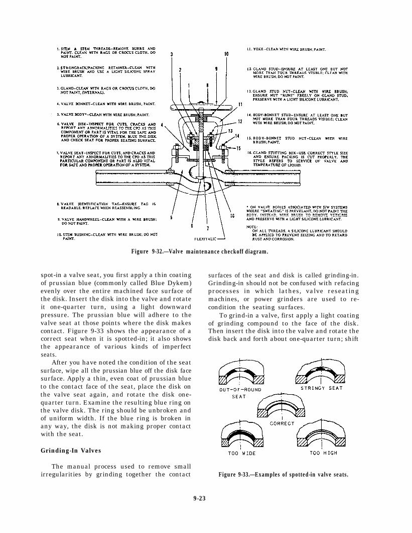
Figure 9-32.—Valve
spot-in a valve seat, you first apply a thin coatingof prussian blue (commonly called Blue Dykem)evenly over the entire machined face surface ofthe disk. Insert the disk into the valve and rotateit one-quarter turn, using a light downwardpressure. The prussian blue will adhere to thevalve seat at those points where the disk makescontact. Figure 9-33 shows the appearance of acorrect seat when it is spotted-in; it also showsthe appearance of various kinds of imperfectseats.
After you have noted the condition of the seatsurface, wipe all the prussian blue off the disk facesurface. Apply a thin, even coat of prussian blueto the contact face of the seat, place the disk onthe valve seat again, and rotate the disk one-quarter turn. Examine the resulting blue ring onthe valve disk. The ring should be unbroken andof uniform width. If the blue ring is broken inany way, the disk is not making proper contactwith the seat.
Grinding-In Valves
maintenance checkoff diagram.
surfaces of the seat and disk is called grinding-in.Grinding-in should not be confused with refacingprocesses in which lathes, valve reseatingmachines, or power grinders are used to re-condition the seating surfaces.
To grind-in a valve, first apply a light coatingof grinding compound to the face of the disk.Then insert the disk into the valve and rotate thedisk back and forth about one-quarter turn; shift
The manual process used to remove smallirregularities by grinding together the contact Figure 9-33.—Examples of spotted-in valve seats.
9-23
the disk-seat relationship from time to time so thedisk will be moved gradually, in increments,through several rotations. During the grindingprocess, the grinding compound will gradually bedisplaced from between the seat and disk surfaces;therefore, you must stop every minute or so toreplenish the compound. When you do this, wipeboth the seat and the disk clean before applyingthe new compound to the disk face.
When you are satisfied that the irregularitieshave been removed, spot-in the disk to the seatin the manner previously described.
Grinding-in is also used to follow up allmachining work on valve seats or disks. When thevalve seat and disk are first spotted-in after theyhave been machined, the seat contact will be verynarrow and will be located close to the bore.Grinding-in, using finer and finer compounds asthe work progresses, causes the seat contact tobecome broader. The contact area should be aperfect ring covering about one-third of theseating surface.
Be careful to avoid overgrinding a valve seator disk. Overgrinding will produce a groove in theseating surface of the disk; it will also roundoff the straight, angular surface of the disk.Machining is the only process by which over-grinding can be corrected.
Lapping Valves
When a valve seat contains irregularities thatare slightly larger than can be satisfactorilyremoved by grinding-in, the irregularities can beremoved by lapping. A cast-iron tool (lap) ofexactly the same size and shape as the valve diskis used to true the valve seat surface. Thefollowing are some precautions you should followwhen lapping valves:
l Do not bear heavily on the handle of thelap.
l Do not bear sideways on the handle of thelap.
l Change the relationship between the lapand the valve seat occasionally so that thelap will gradually and slowly rotate aroundthe entire seat circle.
l Keep a check on the working surface ofthe lap. If a groove develops, have the laprefaced.
l Always use clean compound for lapping.
. Replace the compound frequently.
. Spread the compound evenly and lightly.
l Do not lap more than is necessary toproduce a smooth even seat.
. Always use a fine grinding compound tofinish the lapping job.
. Upon completion of the lapping job, spot-inand grind-in the disk to the seat.
You should use only approved abrasivecompounds for reconditioning valve seats anddisks. Compounds for lapping valve disks andseats are supplied in various grades. Use acoarse grade compound when you find extensivecorrosion or deep cuts and scratches on the disksand seats. Use a medium grade compound as afollow-up to the coarse grade; you may also useit to start the reconditioning process on valves thatare not too severely damaged. Use a fine gradecompound when the reconditioning process nearscompletion. Use a microscopic-fine grade forfinish lapping and for all grinding-in.
Refacing Valves
Badly scored valve seats must be refaced ina lathe, with a power grinder, or with a valvereseating machine. However, the lathe, ratherthan the reseating machine, should be used forrefacing all valve disks and all hard-surfaced valveseats. Work that must be done on a lathe or witha power grinder should be turned over to shoppersonnel.
Repacking Valves
If the stem and packing of a valve are in goodcondition, you can normally stop packing glandleaks by tightening up on the packing. You mustbe careful, however, to avoid excessive threadengagement of the packing gland studs (if used)and to avoid tightening old, hardened packing,which will cause the valve to seize. Subsequentoperation of such a valve may score or bend thestem.
Coils, rings, and corrugated ribbon are thecommon forms of packing used in valves. Theform of packing to be used in repacking aparticular valve will depend on the valvesize, application, and type. Packing materialswill be discussed in more detail later in thischapter.
9-24
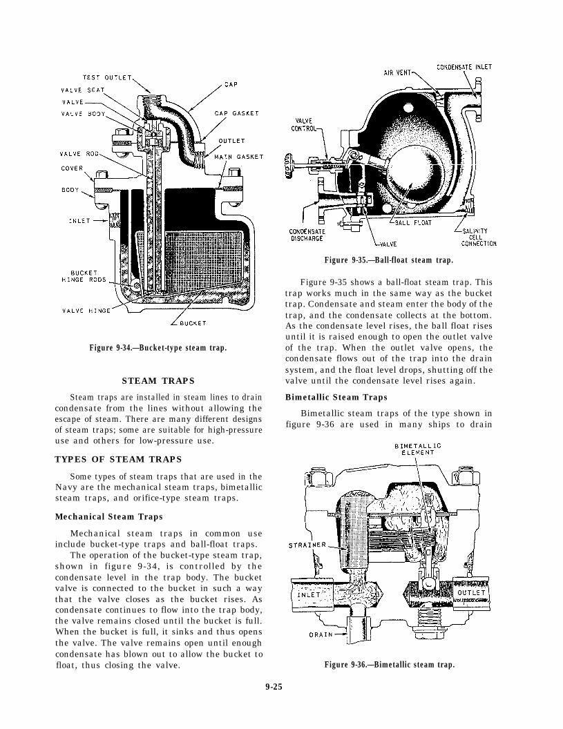
Figure 9-34.—Bucket-type steam trap.
STEAM TRAPS
Steam traps are installed in steam lines to draincondensate from the lines without allowing theescape of steam. There are many different designsof steam traps; some are suitable for high-pressureuse and others for low-pressure use.
TYPES OF STEAM TRAPS
Some types of steam traps that are used in theNavy are the mechanical steam traps, bimetallicsteam traps, and orifice-type steam traps.
Mechanical Steam Traps
Mechanical steam traps in common useinclude bucket-type traps and ball-float traps.
The operation of the bucket-type steam trap,shown in figure 9-34, is controlled by thecondensate level in the trap body. The bucketvalve is connected to the bucket in such a waythat the valve closes as the bucket rises. Ascondensate continues to flow into the trap body,the valve remains closed until the bucket is full.When the bucket is full, it sinks and thus opensthe valve. The valve remains open until enoughcondensate has blown out to allow the bucket tofloat, thus closing the valve.
Figure 9-35.—Ball-float steam trap.
Figure 9-35 shows a ball-float steam trap. Thistrap works much in the same way as the buckettrap. Condensate and steam enter the body of thetrap, and the condensate collects at the bottom.As the condensate level rises, the ball float risesuntil it is raised enough to open the outlet valveof the trap. When the outlet valve opens, thecondensate flows out of the trap into the drainsystem, and the float level drops, shutting off thevalve until the condensate level rises again.
Bimetallic Steam Traps
Bimetallic steam traps of the type shown infigure 9-36 are used in many ships to drain
Figure 9-36.—Bimetallic steam trap.
9-25
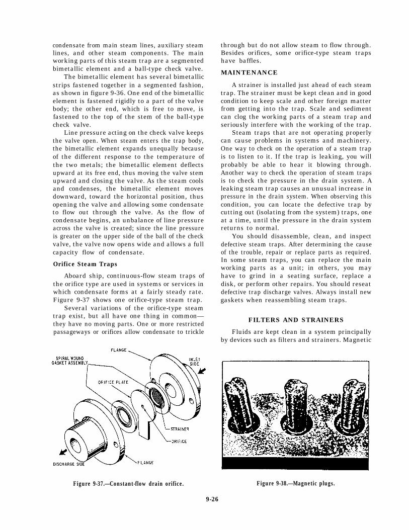
condensate from main steam lines, auxiliary steamlines, and other steam components. The mainworking parts of this steam trap are a segmentedbimetallic element and a ball-type check valve.
The bimetallic element has several bimetallicstrips fastened together in a segmented fashion,as shown in figure 9-36. One end of the bimetallicelement is fastened rigidly to a part of the valvebody; the other end, which is free to move, isfastened to the top of the stem of the ball-typecheck valve.
Line pressure acting on the check valve keepsthe valve open. When steam enters the trap body,the bimetallic element expands unequally becauseof the different response to the temperature ofthe two metals; the bimetallic element deflectsupward at its free end, thus moving the valve stemupward and closing the valve. As the steam coolsand condenses, the bimetallic element movesdownward, toward the horizontal position, thusopening the valve and allowing some condensateto flow out through the valve. As the flow ofcondensate begins, an unbalance of line pressureacross the valve is created; since the line pressureis greater on the upper side of the ball of the checkvalve, the valve now opens wide and allows a fullcapacity flow of condensate.
Orifice Steam Traps
Aboard ship, continuous-flow steam traps ofthe orifice type are used in systems or services inwhich condensate forms at a fairly steady rate.Figure 9-37 shows one orifice-type steam trap.
Several variations of the orifice-type steamtrap exist, but all have one thing in common—they have no moving parts. One or more restrictedpassageways or orifices allow condensate to trickle
through but do not allow steam to flow through.Besides orifices, some orifice-type steam trapshave baffles.
MAINTENANCE
A strainer is installed just ahead of each steamtrap. The strainer must be kept clean and in goodcondition to keep scale and other foreign matterfrom getting into the trap. Scale and sedimentcan clog the working parts of a steam trap andseriously interfere with the working of the trap.
Steam traps that are not operating properlycan cause problems in systems and machinery.One way to check on the operation of a steam trapis to listen to it. If the trap is leaking, you willprobably be able to hear it blowing through.Another way to check the operation of steam trapsis to check the pressure in the drain system. Aleaking steam trap causes an unusual increase inpressure in the drain system. When observing thiscondition, you can locate the defective trap bycutting out (isolating from the system) traps, oneat a time, until the pressure in the drain systemreturns to normal.
You should disassemble, clean, and inspectdefective steam traps. After determining the causeof the trouble, repair or replace parts as required.In some steam traps, you can replace the mainworking parts as a unit; in others, you mayhave to grind in a seating surface, replace adisk, or perform other repairs. You should reseatdefective trap discharge valves. Always install newgaskets when reassembling steam traps.
FILTERS AND STRAINERS
Fluids are kept clean in a system principallyby devices such as filters and strainers. Magnetic
Figure 9-37.—Constant-flow drain orifice.
9-26
Figure 9-38.—Magnetic plugs.
plugs (fig. 9-38) also are used in some strainersto trap iron and steel particles carried by fluid.Studies have indicated that even particles as smallas 1 to 5 microns have a degrading effect, causingfailures and hastening deterioration in many cases.
There will always be controversy over the exactdefinitions of filters and strainers. In the past,many such devices were named filters buttechnically classed as strainers. To minimize thecontroversy, the National Fluid Power Associa-tion gives us these definitions:
FILTER - A device whose primary functionis the retention, by some porous medium, ofinsoluble contaminants from a fluid.
STRAINER - A coarse filter.
To put it simply, whether the device is a filteror a strainer, its function is to trap contaminantsfrom fluid flowing through it. The term porousmedium simply refers to a screen or filteringmaterial that allows fluid flow through it but stopsvarious other materials.
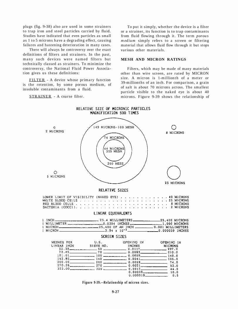
MESH AND MICRON RATINGS
Filters, which may be made of many materialsother than wire screen, are rated by MICRONsize. A micron is 1-millionth of a meter or39-millionths of an inch. For comparison, a grainof salt is about 70 microns across. The smallestparticle visible to the naked eye is about 40microns. Figure 9-39 shows the relationship of
Figure 9-39.—Relationship of micron sizes.
9-27
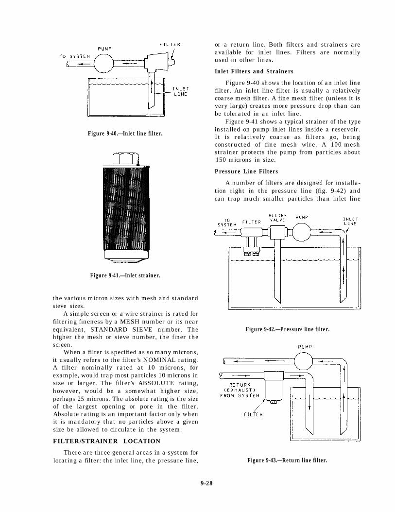
Figure 9-40.—Inlet line filter.
Figure 9-41.—Inlet strainer.
the various micron sizes with mesh and standardsieve sizes.
A simple screen or a wire strainer is rated forfiltering fineness by a MESH number or its nearequivalent, STANDARD SIEVE number. Thehigher the mesh or sieve number, the finer thescreen.
When a filter is specified as so many microns,it usually refers to the filter’s NOMINAL rating.A filter nominally rated at 10 microns, forexample, would trap most particles 10 microns insize or larger. The filter’s ABSOLUTE rating,however, would be a somewhat higher size,perhaps 25 microns. The absolute rating is the sizeof the largest opening or pore in the filter.Absolute rating is an important factor only whenit is mandatory that no particles above a givensize be allowed to circulate in the system.
FILTER/STRAINER LOCATION
There are three general areas in a system forlocating a filter: the inlet line, the pressure line,
or a return line. Both filters and strainers areavailable for inlet lines. Filters are normallyused in other lines.
Inlet Filters and Strainers
Figure 9-40 shows the location of an inlet linefilter. An inlet line filter is usually a relativelycoarse mesh filter. A fine mesh filter (unless it isvery large) creates more pressure drop than canbe tolerated in an inlet line.
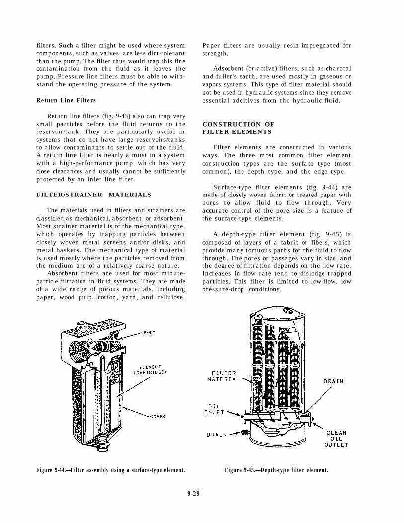
Figure 9-41 shows a typical strainer of the typeinstalled on pump inlet lines inside a reservoir.It is relatively coarse as filters go, beingconstructed of fine mesh wire. A 100-meshstrainer protects the pump from particles about150 microns in size.
Pressure Line Filters
A number of filters are designed for installa-tion right in the pressure line (fig. 9-42) andcan trap much smaller particles than inlet line
Figure 9-42.—Pressure line filter.
Figure 9-43.—Return line filter.
9-28
filters. Such a filter might be used where systemcomponents, such as valves, are less dirt-tolerantthan the pump. The filter thus would trap this finecontamination from the fluid as it leaves thepump. Pressure line filters must be able to with-stand the operating pressure of the system.
Return Line Filters
Return line filters (fig. 9-43) also can trap verysmall particles before the fluid returns to thereservoir/tank. They are particularly useful insystems that do not have large reservoirs/tanksto allow contaminants to settle out of the fluid.A return line filter is nearly a must in a systemwith a high-performance pump, which has veryclose clearances and usually cannot be sufficientlyprotected by an inlet line filter.
FILTER/STRAINER MATERIALS
The materials used in filters and strainers areclassified as mechanical, absorbent, or adsorbent.Most strainer material is of the mechanical type,which operates by trapping particles betweenclosely woven metal screens and/or disks, andmetal baskets. The mechanical type of materialis used mostly where the particles removed fromthe medium are of a relatively coarse nature.
Absorbent filters are used for most minute-particle filtration in fluid systems. They are madeof a wide range of porous materials, includingpaper, wood pulp, cotton, yarn, and cellulose.
Figure 9-44.—Filter assembly using a surface-type element.
Paper filters are usually resin-impregnated forstrength.
Adsorbent (or active) filters, such as charcoaland fuller’s earth, are used mostly in gaseous orvapors systems. This type of filter material shouldnot be used in hydraulic systems since they removeessential additives from the hydraulic fluid.
CONSTRUCTION OFFILTER ELEMENTS
Filter elements are constructed in variousways. The three most common filter elementconstruction types are the surface type (mostcommon), the depth type, and the edge type.
Surface-type filter elements (fig. 9-44) aremade of closely woven fabric or treated paper withpores to allow fluid to flow through. Veryaccurate control of the pore size is a feature ofthe surface-type elements.
A depth-type filter element (fig. 9-45) iscomposed of layers of a fabric or fibers, whichprovide many tortuous paths for the fluid to flowthrough. The pores or passages vary in size, andthe degree of filtration depends on the flow rate.Increases in flow rate tend to dislodge trappedparticles. This filter is limited to low-flow, lowpressure-drop conditions.
Figure 9-45.—Depth-type filter element.
9-29
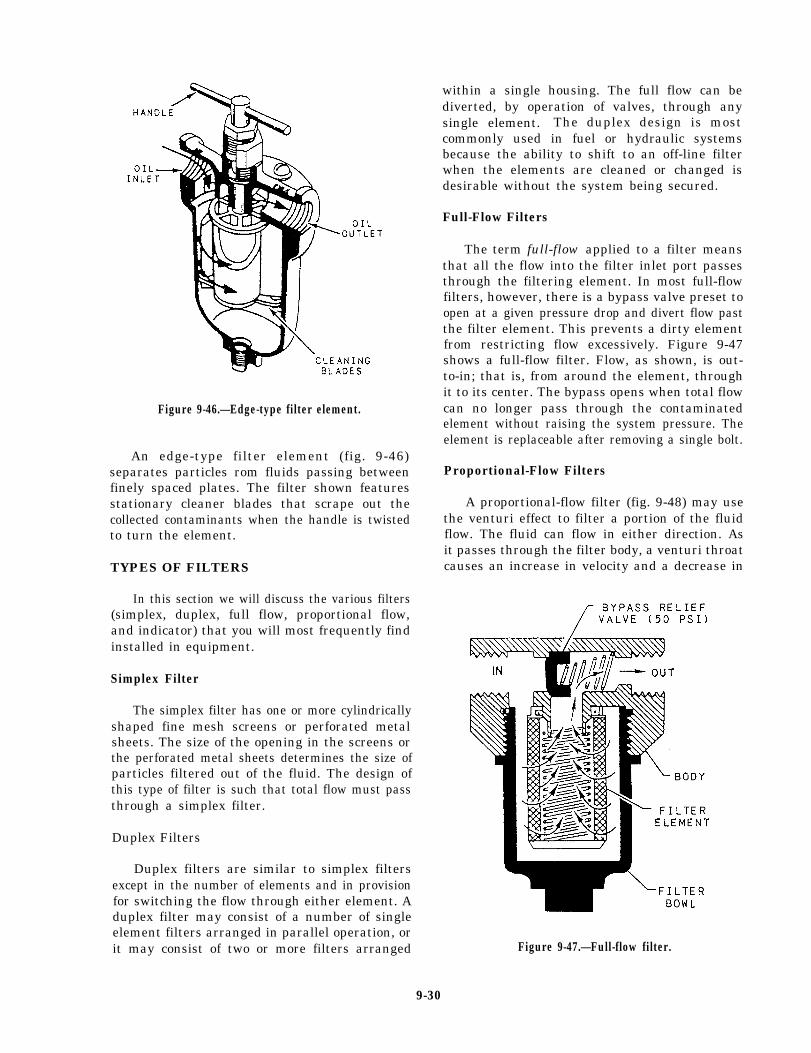
Figure 9-46.—Edge-type filter element.
An edge-type filter element (fig. 9-46)separates particles rom fluids passing betweenfinely spaced plates. The filter shown featuresstationary cleaner blades that scrape out thecollected contaminants when the handle is twistedto turn the element.
TYPES OF FILTERS
In this section we will discuss the various filters(simplex, duplex, full flow, proportional flow,and indicator) that you will most frequently findinstalled in equipment.
Simplex Filter
The simplex filter has one or more cylindricallyshaped fine mesh screens or perforated metalsheets. The size of the opening in the screens orthe perforated metal sheets determines the size ofparticles filtered out of the fluid. The design ofthis type of filter is such that total flow must passthrough a simplex filter.
Duplex Filters
Duplex filters are similar to simplex filtersexcept in the number of elements and in provisionfor switching the flow through either element. Aduplex filter may consist of a number of singleelement filters arranged in parallel operation, orit may consist of two or more filters arranged
within a single housing. The full flow can bediverted, by operation of valves, through anysingle element. The duplex design is mostcommonly used in fuel or hydraulic systemsbecause the ability to shift to an off-line filterwhen the elements are cleaned or changed isdesirable without the system being secured.
Full-Flow Filters
The term full-flow applied to a filter meansthat all the flow into the filter inlet port passesthrough the filtering element. In most full-flowfilters, however, there is a bypass valve preset toopen at a given pressure drop and divert flow pastthe filter element. This prevents a dirty elementfrom restricting flow excessively. Figure 9-47shows a full-flow filter. Flow, as shown, is out-to-in; that is, from around the element, throughit to its center. The bypass opens when total flowcan no longer pass through the contaminatedelement without raising the system pressure. Theelement is replaceable after removing a single bolt.
Proportional-Flow Filters
A proportional-flow filter (fig. 9-48) may usethe venturi effect to filter a portion of the fluidflow. The fluid can flow in either direction. Asit passes through the filter body, a venturi throatcauses an increase in velocity and a decrease in
Figure 9-47.—Full-flow filter.
9-30
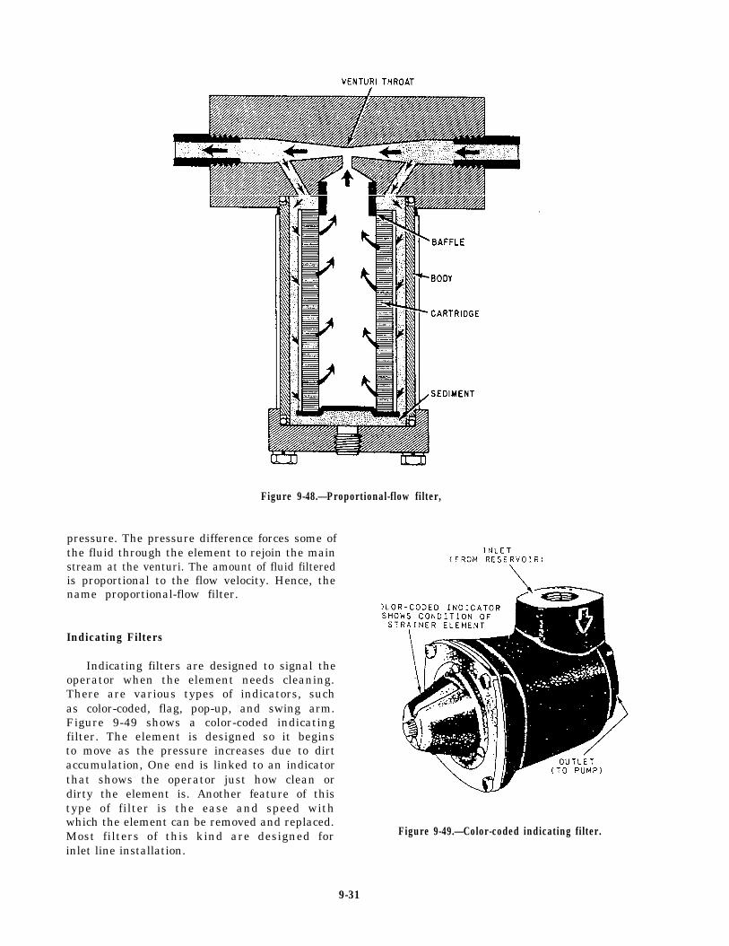
Figure 9-48.—Proportional-flow filter,
pressure. The pressure difference forces some ofthe fluid through the element to rejoin the mainstream at the venturi. The amount of fluid filteredis proportional to the flow velocity. Hence, thename proportional-flow filter.
Indicating Filters
Indicating filters are designed to signal theoperator when the element needs cleaning.There are various types of indicators, suchas color-coded, flag, pop-up, and swing arm.Figure 9-49 shows a color-coded indicatingfilter. The element is designed so it beginsto move as the pressure increases due to dirtaccumulation, One end is linked to an indicatorthat shows the operator just how clean ordirty the element is. Another feature of thistype of filter is the ease and speed withwhich the element can be removed and replaced.Most filters of this kind are designed forinlet line installation.
Figure 9-49.—Color-coded indicating filter.
9-31
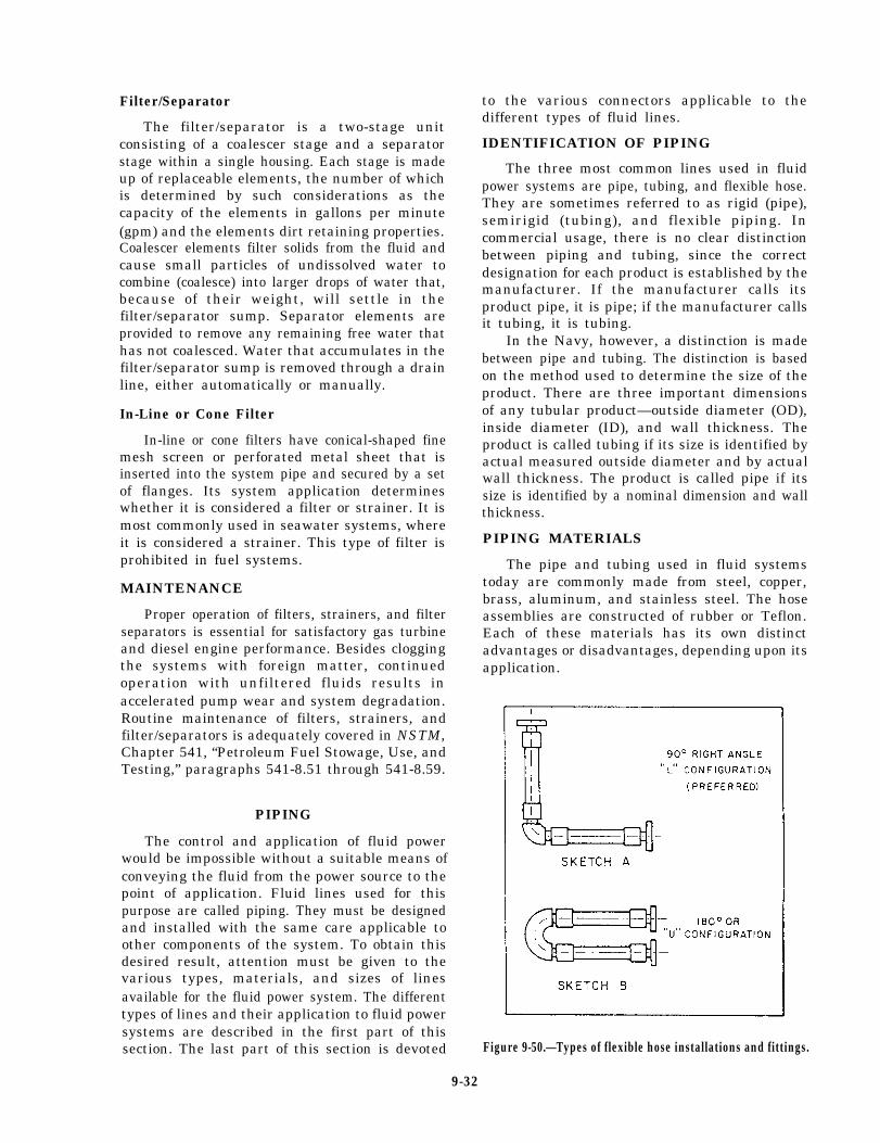
Filter/Separator
The filter/separator is a two-stage unitconsisting of a coalescer stage and a separatorstage within a single housing. Each stage is madeup of replaceable elements, the number of whichis determined by such considerations as thecapacity of the elements in gallons per minute(gpm) and the elements dirt retaining properties.Coalescer elements filter solids from the fluid andcause small particles of undissolved water tocombine (coalesce) into larger drops of water that,because of their weight, will settle in thefilter/separator sump. Separator elements areprovided to remove any remaining free water thathas not coalesced. Water that accumulates in thefilter/separator sump is removed through a drainline, either automatically or manually.
In-Line or Cone Filter
In-line or cone filters have conical-shaped finemesh screen or perforated metal sheet that isinserted into the system pipe and secured by a setof flanges. Its system application determineswhether it is considered a filter or strainer. It ismost commonly used in seawater systems, whereit is considered a strainer. This type of filter isprohibited in fuel systems.
MAINTENANCE
Proper operation of filters, strainers, and filterseparators is essential for satisfactory gas turbineand diesel engine performance. Besides cloggingthe systems with foreign matter, continuedoperation with unfiltered fluids results inaccelerated pump wear and system degradation.Routine maintenance of filters, strainers, andfilter/separators is adequately covered in NSTM,Chapter 541, “Petroleum Fuel Stowage, Use, andTesting,” paragraphs 541-8.51 through 541-8.59.
PIPING
The control and application of fluid powerwould be impossible without a suitable means ofconveying the fluid from the power source to thepoint of application. Fluid lines used for thispurpose are called piping. They must be designedand installed with the same care applicable toother components of the system. To obtain thisdesired result, attention must be given to thevarious types, materials, and sizes of linesavailable for the fluid power system. The differenttypes of lines and their application to fluid powersystems are described in the first part of thissection. The last part of this section is devoted
to the various connectors applicable to thedifferent types of fluid lines.
IDENTIFICATION OF PIPING
The three most common lines used in fluidpower systems are pipe, tubing, and flexible hose.They are sometimes referred to as rigid (pipe),semirigid (tubing), and flexible piping. Incommercial usage, there is no clear distinctionbetween piping and tubing, since the correctdesignation for each product is established by themanufacturer. If the manufacturer calls itsproduct pipe, it is pipe; if the manufacturer callsit tubing, it is tubing.
In the Navy, however, a distinction is madebetween pipe and tubing. The distinction is basedon the method used to determine the size of theproduct. There are three important dimensionsof any tubular product—outside diameter (OD),inside diameter (ID), and wall thickness. Theproduct is called tubing if its size is identified byactual measured outside diameter and by actualwall thickness. The product is called pipe if itssize is identified by a nominal dimension and wallthickness.
PIPING MATERIALS
The pipe and tubing used in fluid systemstoday are commonly made from steel, copper,brass, aluminum, and stainless steel. The hoseassemblies are constructed of rubber or Teflon.Each of these materials has its own distinctadvantages or disadvantages, depending upon itsapplication.
Figure 9-50.—Types of flexible hose installations and fittings.
9-32
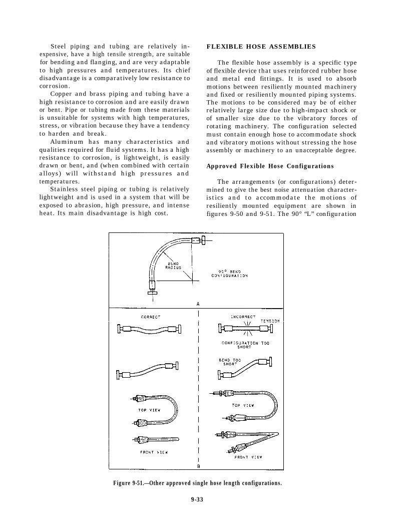
Steel piping and tubing are relatively in-expensive, have a high tensile strength, are suitablefor bending and flanging, and are very adaptableto high pressures and temperatures. Its chiefdisadvantage is a comparatively low resistance tocorrosion.
Copper and brass piping and tubing have ahigh resistance to corrosion and are easily drawnor bent. Pipe or tubing made from these materialsis unsuitable for systems with high temperatures,stress, or vibration because they have a tendencyto harden and break.
Aluminum has many characteristics andqualities required for fluid systems. It has a highresistance to corrosion, is lightweight, is easilydrawn or bent, and (when combined with certainalloys) will withstand high pressures andtemperatures.
Stainless steel piping or tubing is relativelylightweight and is used in a system that will beexposed to abrasion, high pressure, and intenseheat. Its main disadvantage is high cost.
FLEXIBLE HOSE ASSEMBLIES
The flexible hose assembly is a specific typeof flexible device that uses reinforced rubber hoseand metal end fittings. It is used to absorbmotions between resiliently mounted machineryand fixed or resiliently mounted piping systems.The motions to be considered may be of eitherrelatively large size due to high-impact shock orof smaller size due to the vibratory forces ofrotating machinery. The configuration selectedmust contain enough hose to accommodate shockand vibratory motions without stressing the hoseassembly or machinery to an unacceptable degree.
Approved Flexible Hose Configurations
The arrangements (or configurations) deter-mined to give the best noise attenuation character-istics and to accommodate the motions ofresiliently mounted equipment are shown infigures 9-50 and 9-51. The 90° “L” configuration
Figure 9-51.—Other approved single hose length configurations.
9-33
(dogleg) is the preferred configuration; however,where space and piping arrangement prohibit theuse of the “L” configuration, a 180° or “U”configuration may be used. The 90° “L” and180° “U” configurations are shown as sketchesA and B of figure 9-50.
A configuration that uses a single length ofhose bent to about 90° is approved where the hosedoes not bend below its specified minimumbending radius when the equipment moves to themaximum limits allowed by its mounts (view Aof fig. 9-51). The straight single hose configura-tion and the 180° single hose bend (view B of fig.9-51) are also approved for use where the hosesize is less than 1 inch ID.
Flexible connections that use rubber hose arenot used in systems where the maximumcontinuous operating temperature is in excess of200°F.
Hose Identification
Hose is identified by the manufacturer’s partnumber and the size or dash number. The dashnumber is the nominal hose inside diameter insixteenths of an inch. Hose built to militaryspecification (MILSPEC) requirements have thenumber of the specification and, where applicable,the class of hose, the quarter and year of manu-facture, and the manufacturer’s trademark. Thisinformation is molded or otherwise permanentlyrepeated periodically on the hose cover (sometimesreferred to as the “lay line marking”). Otherinformation permanently marked on the hosecover is the manufacturer’s code and the date ofmanufacture. For interpretations of commerciallay line markings, refer to the appropriatemanufacturer’s catalog or manual.
Fitting Identification
Use special care in identifying hose fittingsbecause their designation is more complex thanhose. A fitting suitable for connecting to a givenhose size can end in more than one size and typeof connection to the piping. A fitting, therefore,must be identified by the manufacturer’s partnumber, the size of the end connection that joinsthe piping system, and the dash size to show thesize hose to which it makes up. For interpreta-tion of manufacturer markings, consult theappropriate manufacturer’s manual. Fittingsmeeting military specification requirements havethe specification number, class of fitting (whereapplicable), type, size, and manufacturer’strademark.
A cross index between the manufacturers’designations and military specifications andinformation to correctly identify approved hosesand fittings can be found in Piping Devices,Flexible Hose Assemblies, volume 1, NAVSEAS6430-AE-TED-010.
Inspection of Hose andFittings Prior To Make-Up
The basic inspection methods for hose andfittings are listed as follows:
1.
2.
3.
4.
5.
6.
Ensure that the hose and couplings are thecorrect ones for the intended use and thatthe age of the rubber hose does not exceeda shelf life of 4 years. Teflon and metalhose have no limiting shelf life.Inspect for signs that the hose has beentwisted. Use the hose lay line for a guideto determine whether or not any twist ispresent. If twisted, reject.Inspect for signs that the hose has beenkinked or bent beyond its minimum bendradius. If suspect, reject.Inspect for signs of loose inner liner. Iffound, cut the hose to see if this conditionexists throughout the entire length. If.suspect, reject.Visually check the inner liner and outerrubber cover of the hose for breaks,hairline cuts, or severe abrasions. If anysuspect areas are found, reject.Inspect the fittings for defects, such ascracked nipples and damaged threads.If suspect, or if defects are found, reject.
Procedures for making up hoses and fittingscan also be found in the NSTM, chapter 505, orthe appropriate manufacturer’s catalog ormanual, and are not covered here due to the manytypes available.
Visual Inspection
After assembling the hose and fittings, visuallyinspect the entire configuration to ensure thefollowing:
1.
2.
The hose inner liner and outer cover isintact and contains no cuts or harmfulabrasions.The hose has not been twisted (check thelay line).
9-34
3.
4.
The circumferential chalk line on the hosenext to the coupling has been drawn beforethe hydrostatic test.
The internal spring (if installed) is evenlyspaced and flat against the inner liner.Ensure a gap exists between one of the endfittings and the end of the spring.
Hydrostatic Test
Upon completion of visual inspection, hydro-statically shop test the hose assembly with freshwater. For each style and size of hose, test thepressure to ensure that it is twice the maximumallowable pressure shown in chapter 505 of theNSTM. When you test pressure, hold for notmore than 5 minutes nor less than 60 seconds.When test pressure is reached, visually inspect thehose assembly for the following defects:
1. Leaks or signs of weakness
2. Twisting of the hose (this indicates thatsome twist existed before pressure wasapplied)
3. Slippage of the hose out of the coupling(a circumferential chalk line can help deter-mine this)
If any of these defects occur, reject theassembly.
CAUTION
Do not confuse hose elongation underpressure with coupling slippage. If thechalk line returns to near its originalposition, no slippage has occurred and theassembly is satisfactory. If there is anydoubt, perform a second test. If doubtpersists after the second test, reject theassembly.
Air Test
Hose assemblies intended for gas or airservice must also be tested with air or nitrogenat 100 psi and the assembly immersed in water.Random bubbles may appear over the hose and
in the fitting area when the assembly is firstpressurized. Do not construe this as a defect.However, if the bubbles persist in forming at asteady rate at any particular point on the hose,reject the assembly.
Installation of Flexible Hose Assemblies
After completion of tests, proceed as follows:
1.
2.
3.
4.
Install as soon as possible.
Do not leave the hose assembly around ondecks or on docks where they can be sub-jected to any form of abuse.
Make up hose assemblies as late aspossible during the availability schedule tominimize the chances of damage while theship is being overhauled.
Install plastic dust caps, plugs, or tape endsto protect threaded areas until the hoseassembly is installed.
When installing flexible base connections,observe the following requirements:
1.
2.
3.
4.
5.
6.
Ensure each leg of hose is free of twistbetween end fittings.
Ensure the fixed piping near the flexibleconfiguration is properly supported so thatit does not vibrate from the resilientlymounted equipment.
Ensure the configurations are clear of allsurrounding structures and remain so whenresiliently mounted equipment movesthrough its maximum excursion undershock.
Locate flexible connections as close aspossible to the sound-mounted unit.
Support the free elbow of the configura-tion with an approved pipe hanger so asnot to sag or otherwise unduly stress ordistort the configuration.
Do not appreciably change the alignmentof the hose configuration between the un-pressurized and pressurized conditions. Ifyou do, you could cause misalignment orimproper support at the fixed end.
9-35
Figure 9-52.-Hose assembly identification tags.
7.
8.
Obtain metal hose assembly identificationtags (fig. 9-52) from your local SIMA andsecure them onto one of the legs of the hoseconfiguration. The tag is made of a non-corroding material. Do not remove or alterthe tag once it is attached.Leave the configuration in a conditionwhere one end can hang down unsupportedduring installation or dismantling of piping.Otherwise, you can damage the hose wirereinforcement.
Periodic Inspection By Ship’s Force
No less than once a quarter, preferably aboutonce a month, visually inspect all flexible pipingconnections to determine whether any signs ofweakness or unusual conditions exist. Inspect thehose in other systems semiannually. To assist youwhen performing this inspection, you shouldcompile a checkoff list of hose assemblies andlocations for your assigned spaces or equipment.This list will consist of all flexible devicesinstalled (and their locations) together with a listof inspections to be performed on each flexibledevice. When you perform the listed inspections,note the following:
1.2.
Evidence of leakage at fitting ends.Discoloration of fittings (possible indica-tion wire reinforcement is rusting).
9-36
3.4.
5.6.
7.
8.
9.
10.
11.(indicates weakening of bond betweenouter rubber cover and wire braid ordeterioration of the reinforcing wire).
12.
Slippage of hose out of fitting.Twisting of hose or other distortion orunusual appearance.Cracking of outer rubber cover.Rubber cover rubbed thin by abrasion orchafing.High pulsations, fluid hammer, or whippingcaused by pressure pulsations.Large vibrations due to improper supportsat the fixed end.Large area of hose covered with paint.(The intent of this requirement is toeliminate having the flexible hose con-nections deliberately painted. The hosedoes not have to be replaced if a few paintdrops inadvertently fall onto it. Do notattempt to clean off dried paint from thehose.)Check hangers to ensure they have notbroken off, become distorted, or beenotherwise damaged.Soft spots or bulges on hose body
If results of visual inspection indicatesweakening of hose or fittings, or makeshose configuration suspect, replace thehose immediately, if at all possible. Keepunder surveillance while under pressureuntil it is replaced.
13.
14.
If necessary to remove a flexible hose con-figuration from the system, examine theinterior of the hose for cracks or othersigns of deterioration of the inner liner.Do not damage the liner by trying todislodge sea growth. Do not remove theend fittings from any section of hose thatis to be installed.Presence of identification tag.
Storage
The following guidelines are recommended forproper storage of hose and fittings:
Hose—Hose should be stored in a dark,dry atmosphere away from electrical equip-ment; temperature should not exceed 125°“F.Storage in straight lengths is preferred, butif hose is to be coiled, take care to ensurethe diameter of the bend is not less than 3feet. To prevent damage during storage,wrap the hose with burlap or other suitable
Reusable end fittings—Protect all threads
material.
damage.
with tape or other suitable material, andwrap the entire fitting in a protectivecovering to prevent nicking or other
Shelf Life
The following are shelf life requirements for hoseand reusable end fittings:
Hose—Do not install reinforced rubber hosethat is over 4 years old from the date ofmanufacture. This time is measured from thequarter and year of manufacture but doesnot include the quarter year of manufacture.Consider the shelf life of hose ended uponinstallation aboard ship. To ensure againstits accidental use, dispose of any hose notinstalled that has exceeded the above shelflife.
Reusable end fittings—There is no shelf lifefor end fittings. They should be replaced onan individual basis when examination makesthem suspect.
Servicing
No servicing or maintenance is required sincehose or fittings must be replaced at the slightestsuspicion of potential failure. If a fitting isremoved from a section of hose, that hose sectionmust not be reused, regardless of its service life.
Service Life of Rubber Hose
All rubber hose has a periodic replacement time.All flexible rubber hose connections will be replacedevery 5 years ( * 6 months) in critical systems andevery 12 years in noncritical systems. Wire braidedTeflon hose has no specified shelf or service life.Its replacement is based on inspection of the hosefor excessive wear or damage.
FITTINGS
Some type of connector must be provided to at-tach the pipe, tube, or hose to the other componentsof the system and to connect sections of the line toeach other. There are many different types of con-nectors (commonly called fittings) provided for thispurpose. Some of the most common types of fittingsare covered in the following paragraphs.
Threaded Joints
The threaded joints are the simplest type ofpipe fittings. Threaded fittings are not widely usedaboard modern ships except in low-pressure waterpiping systems. The pipe ends connected to theunion are threaded, silver-brazed, or weldedinto the tail pieces (union halves); then the twoends are joined by setting up (engaging andtightening up on) the union ring. The male andfemale connecting ends of the tail pieces arecarefully ground to make a tight metal-to-metalfit with each other. Welding or silver-brazing theends to the tail pieces prevents contact of thecarried fluid or gas with the union threading.
Bolted Flange Joints
Bolted flange joints (fig. 9-53) are suitable forall pressures now in use. The flanges are attached
Figure 9-53.—Four types of bolted flange piping joints.
9-37
Figure 9-54.—Various types of welded joints.
to the piping by welding, brazing, screw threads(for some low-pressure piping), or rolling andbending into recesses. Those shown in figure 9-53are the most common types of flange joints used.Flange joints are manufactured for all standardfitting shapes, such as the tee, cross, elbow, andreturn bend. The Van Stone and the welded-neckflange joints are used extensively where piping issubjected to high pressures and heavy expansionstrains. The design of the Van Stone flange makesit easier to line up the fastening holes in the twoparts of the flange.
Welded Joints
The majority of joints found in subassembliesof piping systems are welded joints, especiallyin high-pressure piping. The welding is doneaccording to standard specifications, which definethe material and techniques. Three general classesof welded joints are fillet-weld, butt-weld, andsocket-weld (fig. 9-54).
Silver-Brazed Joints
Silver-brazed joints (fig. 9-55) are commonlyused for joining nonferrous piping when thepressure and temperature in the lines make theiruse practicable—temperatures must not exceed425°F; for cold lines, pressure must not exceed3000 psi. The alloy is melted by heating the jointwith an oxyacetylene torch. This causes the moltenmetal to fill the few thousandths of an inchannular space between the pipe and the fitting.
Unions
The union fittings are provided in pipingsystems to allow the piping to be taken down for
Figure 9-55.—Silver-brazed joints.
9-38
Figure 9-56.—Unions/threaded pipe connectors.
Figure 9-57.-Flared-tube fittings.repairs and alterations. Unions are available inmany different materials and designs to withstanda wide range of pressures and temperatures.Figure 9-56 shows some commonly used types ofunions/threaded pipe connectors. The union ismost commonly used for joining piping up to 2inches in size.
Flared Fittings
Flared fittings are commonly used in tubinglines. These fittings provide safe, strong,dependable connections without the necessity ofthreading, welding, or soldering the tubing. Flaredfittings are made of steel, aluminum alloy, orbronze. Do not mix materials when using thesefittings. For example, for steel tubing use onlysteel fittings and for copper or brass tubing useonly bronze fittings, Figure 9-57 shows the mostcommon types of flared fittings.
Figure 9-58.-Double-male flareless fitting.
Flareless Fittings
Flareless fittingssuitable for use in
(figs. 9-58 and 9-59) arehydraulic service and air Figure 9-59.—Typical flareless fitting.
9-39
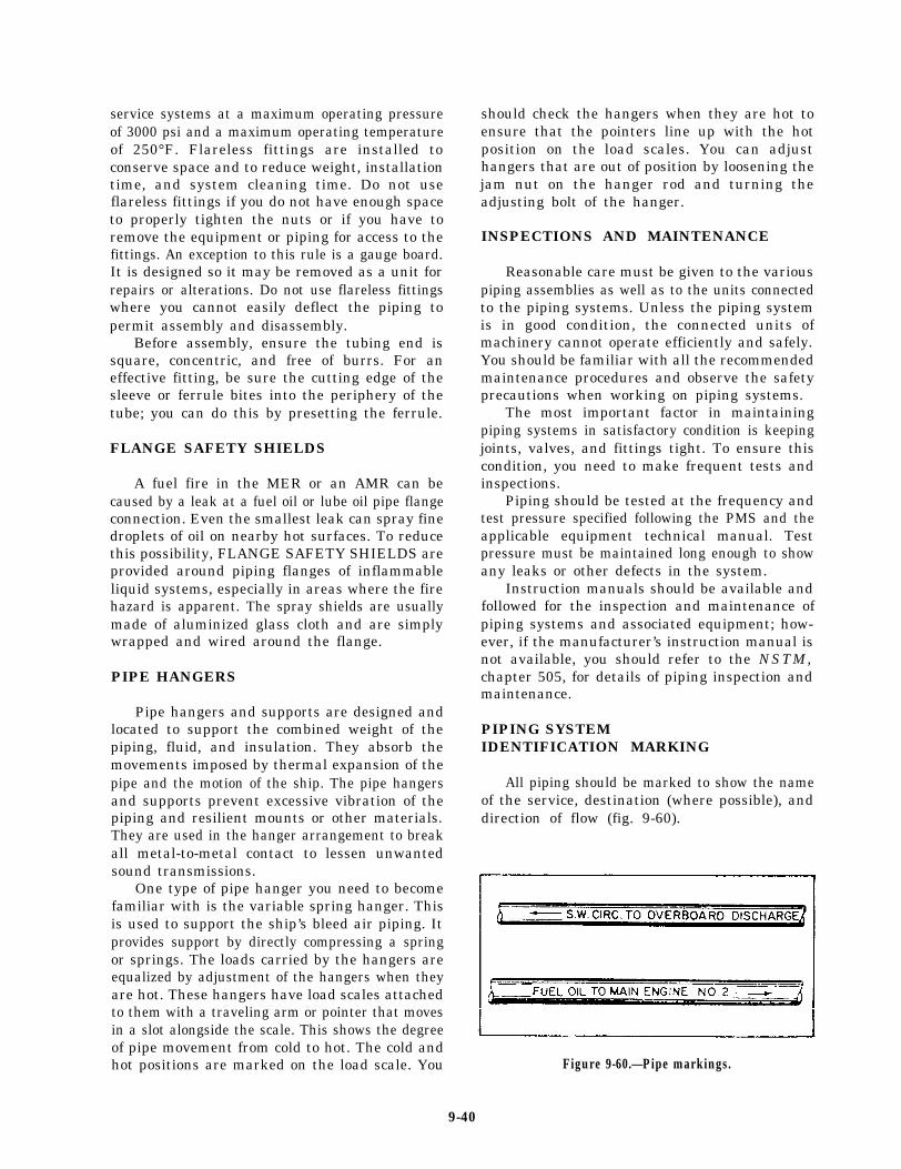
service systems at a maximum operating pressureof 3000 psi and a maximum operating temperatureof 250°F. Flareless fittings are installed toconserve space and to reduce weight, installationtime, and system cleaning time. Do not useflareless fittings if you do not have enough spaceto properly tighten the nuts or if you have toremove the equipment or piping for access to thefittings. An exception to this rule is a gauge board.It is designed so it may be removed as a unit forrepairs or alterations. Do not use flareless fittingswhere you cannot easily deflect the piping topermit assembly and disassembly.
Before assembly, ensure the tubing end issquare, concentric, and free of burrs. For aneffective fitting, be sure the cutting edge of thesleeve or ferrule bites into the periphery of thetube; you can do this by presetting the ferrule.
FLANGE SAFETY SHIELDS
A fuel fire in the MER or an AMR can becaused by a leak at a fuel oil or lube oil pipe flangeconnection. Even the smallest leak can spray finedroplets of oil on nearby hot surfaces. To reducethis possibility, FLANGE SAFETY SHIELDS areprovided around piping flanges of inflammableliquid systems, especially in areas where the firehazard is apparent. The spray shields are usuallymade of aluminized glass cloth and are simplywrapped and wired around the flange.
PIPE HANGERS
Pipe hangers and supports are designed andlocated to support the combined weight of thepiping, fluid, and insulation. They absorb themovements imposed by thermal expansion of thepipe and the motion of the ship. The pipe hangersand supports prevent excessive vibration of thepiping and resilient mounts or other materials.They are used in the hanger arrangement to breakall metal-to-metal contact to lessen unwantedsound transmissions.
One type of pipe hanger you need to becomefamiliar with is the variable spring hanger. Thisis used to support the ship’s bleed air piping. Itprovides support by directly compressing a springor springs. The loads carried by the hangers areequalized by adjustment of the hangers when theyare hot. These hangers have load scales attachedto them with a traveling arm or pointer that movesin a slot alongside the scale. This shows the degreeof pipe movement from cold to hot. The cold andhot positions are marked on the load scale. You
should check the hangers when they are hot toensure that the pointers line up with the hotposition on the load scales. You can adjusthangers that are out of position by loosening thejam nut on the hanger rod and turning theadjusting bolt of the hanger.
INSPECTIONS AND MAINTENANCE
Reasonable care must be given to the variouspiping assemblies as well as to the units connectedto the piping systems. Unless the piping systemis in good condition, the connected units ofmachinery cannot operate efficiently and safely.You should be familiar with all the recommendedmaintenance procedures and observe the safetyprecautions when working on piping systems.
The most important factor in maintainingpiping systems in satisfactory condition is keepingjoints, valves, and fittings tight. To ensure thiscondition, you need to make frequent tests andinspections.
Piping should be tested at the frequency andtest pressure specified following the PMS and theapplicable equipment technical manual. Testpressure must be maintained long enough to showany leaks or other defects in the system.
Instruction manuals should be available andfollowed for the inspection and maintenance ofpiping systems and associated equipment; how-ever, if the manufacturer’s instruction manual isnot available, you should refer to the NSTM,chapter 505, for details of piping inspection andmaintenance.
PIPING SYSTEMIDENTIFICATION MARKING
All piping should be marked to show the nameof the service, destination (where possible), anddirection of flow (fig. 9-60).
Figure 9-60.—Pipe markings.
9-40
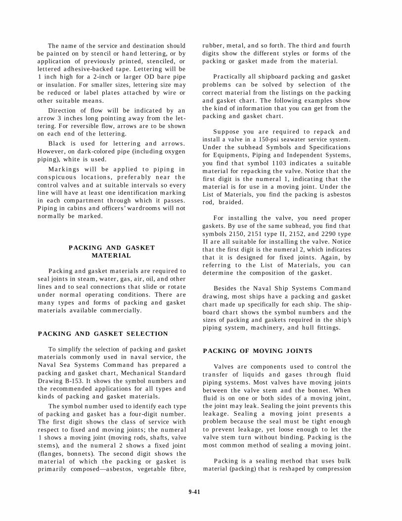
The name of the service and destination shouldbe painted on by stencil or hand lettering, or byapplication of previously printed, stenciled, orlettered adhesive-backed tape. Lettering will be1 inch high for a 2-inch or larger OD bare pipeor insulation. For smaller sizes, lettering size maybe reduced or label plates attached by wire orother suitable means.
Direction of flow will be indicated by anarrow 3 inches long pointing away from the let-tering. For reversible flow, arrows are to be shownon each end of the lettering.
Black is used for lettering and arrows.However, on dark-colored pipe (including oxygenpiping), white is used.
Markings will be applied to piping inconspicuous locations, preferably near thecontrol valves and at suitable intervals so everyline will have at least one identification markingin each compartment through which it passes.Piping in cabins and officers’ wardrooms will notnormally be marked.
PACKING AND GASKETMATERIAL
Packing and gasket materials are required toseal joints in steam, water, gas, air, oil, and otherlines and to seal connections that slide or rotateunder normal operating conditions. There aremany types and forms of packing and gasketmaterials available commercially.
PACKING AND GASKET SELECTION
To simplify the selection of packing and gasketmaterials commonly used in naval service, theNaval Sea Systems Command has prepared apacking and gasket chart, Mechanical StandardDrawing B-153. It shows the symbol numbers andthe recommended applications for all types andkinds of packing and gasket materials.
The symbol number used to identify each typeof packing and gasket has a four-digit number.The first digit shows the class of service withrespect to fixed and moving joints; the numeral1 shows a moving joint (moving rods, shafts, valvestems), and the numeral 2 shows a fixed joint(flanges, bonnets). The second digit shows thematerial of which the packing or gasket isprimarily composed—asbestos, vegetable fibre,
rubber, metal, and so forth. The third and fourthdigits show the different styles or forms of thepacking or gasket made from the material.
Practically all shipboard packing and gasketproblems can be solved by selection of thecorrect material from the listings on the packingand gasket chart. The following examples showthe kind of information that you can get from thepacking and gasket chart.
Suppose you are required to repack andinstall a valve in a 150-psi seawater service system.Under the subhead Symbols and Specificationsfor Equipments, Piping and Independent Systems,you find that symbol 1103 indicates a suitablematerial for repacking the valve. Notice that thefirst digit is the numeral 1, indicating that thematerial is for use in a moving joint. Under theList of Materials, you find the packing is asbestosrod, braided.
For installing the valve, you need propergaskets. By use of the same subhead, you find thatsymbols 2150, 2151 type II, 2152, and 2290 typeII are all suitable for installing the valve. Noticethat the first digit is the numeral 2, which indicatesthat it is designed for fixed joints. Again, byreferring to the List of Materials, you candetermine the composition of the gasket.
Besides the Naval Ship Systems Commanddrawing, most ships have a packing and gasketchart made up specifically for each ship. The ship-board chart shows the symbol numbers and thesizes of packing and gaskets required in the ship’spiping system, machinery, and hull fittings.
PACKING OF MOVING JOINTS
Valves are components used to control thetransfer of liquids and gases through fluidpiping systems. Most valves have moving jointsbetween the valve stem and the bonnet. Whenfluid is on one or both sides of a moving joint,the joint may leak. Sealing the joint prevents thisleakage. Sealing a moving joint presents aproblem because the seal must be tight enoughto prevent leakage, yet loose enough to let thevalve stem turn without binding. Packing is themost common method of sealing a moving joint.
Packing is a sealing method that uses bulkmaterial (packing) that is reshaped by compression
9-41
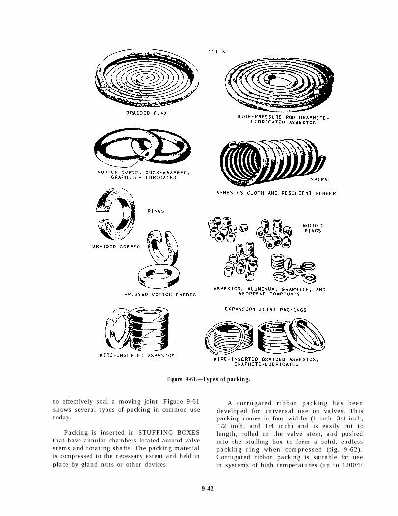
Figure
to effectively seal a moving joint. Figure 9-61shows several types of packing in common usetoday.
Packing is inserted in STUFFING BOXESthat have annular chambers located around valvestems and rotating shafts. The packing materialis compressed to the necessary extent and held inplace by gland nuts or other devices.
9-61.—Types of packing.
A corrugated ribbon packing has beendeveloped for universal use on valves. Thispacking comes in four widths (1 inch, 3/4 inch,1/2 inch, and 1/4 inch) and is easily cut tolength, rolled on the valve stem, and pushedinto the stuffing box to form a solid, endlesspacking ring when compressed (fig. 9-62).Corrugated ribbon packing is suitable for usein systems of high temperatures (up to 1200°F
9-42
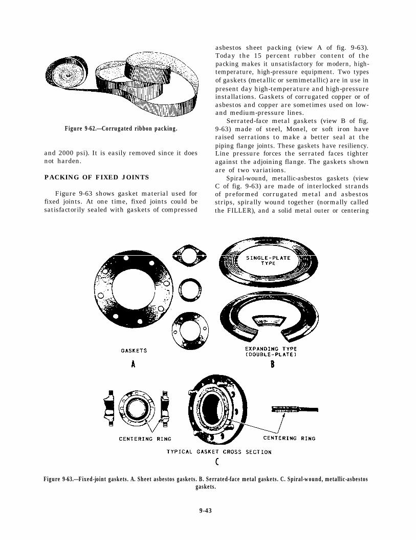
Figure 9-62.—Corrugated ribbon packing.
and 2000 psi). It is easily removed since it doesnot harden.
PACKING OF FIXED JOINTS
Figure 9-63 shows gasket material used forfixed joints. At one time, fixed joints could besatisfactorily sealed with gaskets of compressed
asbestos sheet packing (view A of fig. 9-63).Today the 15 percent rubber content of thepacking makes it unsatisfactory for modern, high-temperature, high-pressure equipment. Two typesof gaskets (metallic or semimetallic) are in use inpresent day high-temperature and high-pressureinstallations. Gaskets of corrugated copper or ofasbestos and copper are sometimes used on low-and medium-pressure lines.
Serrated-face metal gaskets (view B of fig.9-63) made of steel, Monel, or soft iron haveraised serrations to make a better seal at thepiping flange joints. These gaskets have resiliency.Line pressure forces the serrated faces tighteragainst the adjoining flange. The gaskets shownare of two variations.
Spiral-wound, metallic-asbestos gaskets (viewC of fig. 9-63) are made of interlocked strandsof preformed corrugated metal and asbestosstrips, spirally wound together (normally calledthe FILLER), and a solid metal outer or centering
Figure 9-63.—Fixed-joint gaskets. A. Sheet asbestos gaskets. B. Serrated-face metal gaskets. C. Spiral-wound, metallic-asbestosgaskets.
9-43
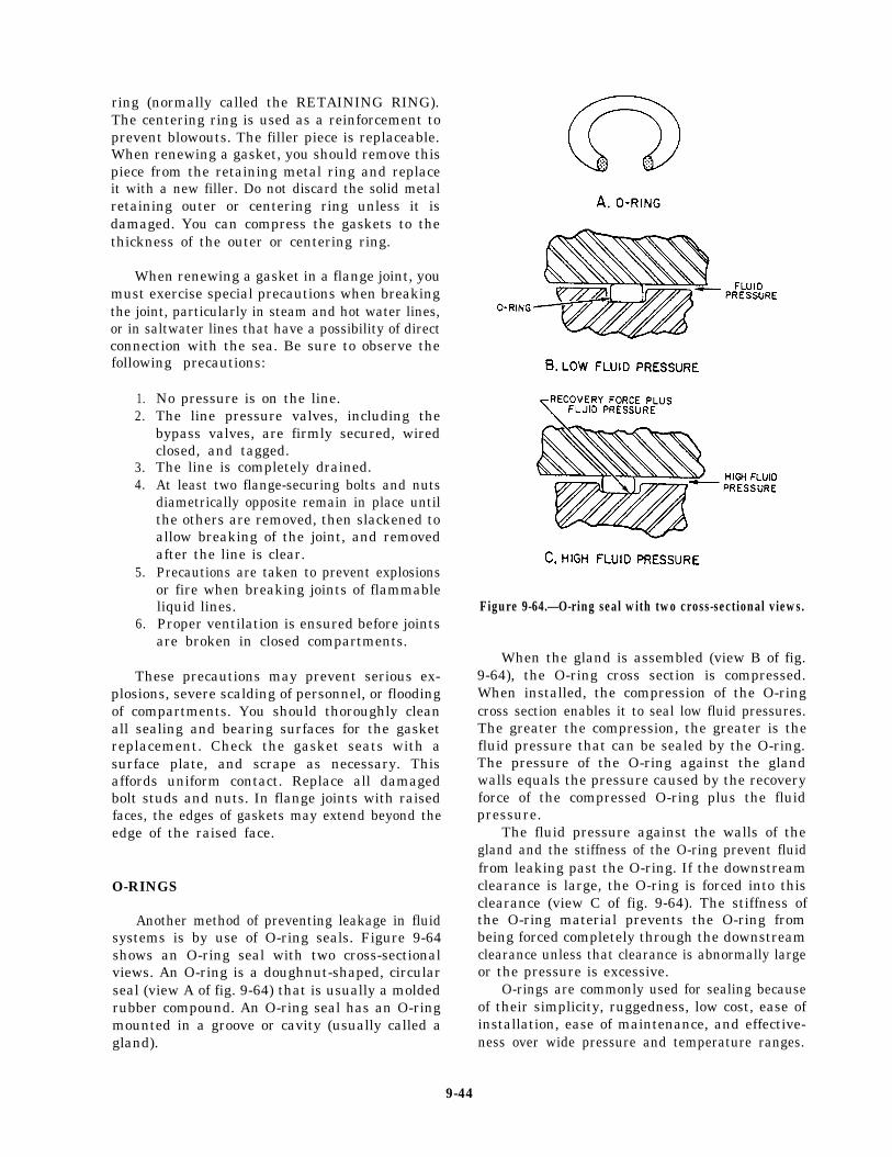
ring (normally called the RETAINING RING).The centering ring is used as a reinforcement toprevent blowouts. The filler piece is replaceable.When renewing a gasket, you should remove thispiece from the retaining metal ring and replaceit with a new filler. Do not discard the solid metalretaining outer or centering ring unless it isdamaged. You can compress the gaskets to thethickness of the outer or centering ring.
When renewing a gasket in a flange joint, youmust exercise special precautions when breakingthe joint, particularly in steam and hot water lines,or in saltwater lines that have a possibility of directconnection with the sea. Be sure to observe thefollowing precautions:
1.2.
3.4.
5.
6.
No pressure is on the line.The line pressure valves, including thebypass valves, are firmly secured, wiredclosed, and tagged.The line is completely drained.At least two flange-securing bolts and nutsdiametrically opposite remain in place untilthe others are removed, then slackened toallow breaking of the joint, and removedafter the line is clear.Precautions are taken to prevent explosionsor fire when breaking joints of flammableliquid lines.Proper ventilation is ensured before jointsare broken in closed compartments.
These precautions may prevent serious ex-plosions, severe scalding of personnel, or floodingof compartments. You should thoroughly cleanall sealing and bearing surfaces for the gasketreplacement. Check the gasket seats with asurface plate, and scrape as necessary. Thisaffords uniform contact. Replace all damagedbolt studs and nuts. In flange joints with raisedfaces, the edges of gaskets may extend beyond theedge of the raised face.
O-RINGS
Another method of preventing leakage in fluidsystems is by use of O-ring seals. Figure 9-64shows an O-ring seal with two cross-sectionalviews. An O-ring is a doughnut-shaped, circularseal (view A of fig. 9-64) that is usually a moldedrubber compound. An O-ring seal has an O-ringmounted in a groove or cavity (usually called agland).
Figure 9-64.—O-ring seal with two cross-sectional views.
When the gland is assembled (view B of fig.9-64), the O-ring cross section is compressed.When installed, the compression of the O-ringcross section enables it to seal low fluid pressures.The greater the compression, the greater is thefluid pressure that can be sealed by the O-ring.The pressure of the O-ring against the glandwalls equals the pressure caused by the recoveryforce of the compressed O-ring plus the fluidpressure.
The fluid pressure against the walls of thegland and the stiffness of the O-ring prevent fluidfrom leaking past the O-ring. If the downstreamclearance is large, the O-ring is forced into thisclearance (view C of fig. 9-64). The stiffness ofthe O-ring material prevents the O-ring frombeing forced completely through the downstreamclearance unless that clearance is abnormally largeor the pressure is excessive.
O-rings are commonly used for sealing becauseof their simplicity, ruggedness, low cost, ease ofinstallation, ease of maintenance, and effective-ness over wide pressure and temperature ranges.
9-44
Failure of an O-ring can sometimes begin withthe removal of an old O-ring. If you incorrectlyremove an O-ring with pointed or sharp tools, youcan scratch or dent critical surface finishes thatcan result in seal failure.
Before installing a new O-ring, inspect thesealing surfaces for any abrasions and wipe themfree of any dust, dirt, or other contaminants.Before installation, inspect the O-ring for anydamage. If faulty, discard it.
When you install the O-ring, lubricate it. Inmost cases it is already coated with the systemfluid or petrolatum grease. Do not stretch theO-ring more than twice its original size duringinstallation, and do not roll or twist it intoplace. This may leave a permanent twist in theO-ring and reduce its effectiveness and shortenits life.
When installing an O-ring, take extremecare to avoid forcing it over sharp edges,corners, and threaded sections. You should usesome type of sleeve or cover to avoid damagingthe O-ring.
FASTENERS
The proper use of fasteners is very importantand cannot be overemphasized. Many shipboardmachinery casualties have resulted from fastenersthat were not properly installed. Machineryvibration, thermal expansion, and thermalcontraction will loosen the fasteners. At sea,loosening effects are increased by the pitch androll of the ship. You are familiar with suchstandard fasteners as nuts, bolts, washers,wingnuts, and screws. In this section we willdiscuss some of the new developments in fastenertechnology, such as the various types of locknuts,which you may not be familiar with.
THREADED LOCKING DEVICES
An important part of fastener technology hasincluded the development of several methods forlocking mated threads of fasteners. Many of thelatest methods include the locking device ormethod as an integral part of the fastenerassembly and are referred to as self-lockingnuts or bolts. Self-locking fasteners are more
expensive than some older methods but comparefavorably in cost with pin or wiring methods.
Length of Protrusion
Male threads on threaded fasteners, wheninstalled and tightened, will protrude the distanceof at least one thread length beyond thetop of the nut or plastic locking ring. Excessiveprotrusion is a hazard, particularly wherenecessary clearances, accessibility, and safety areimportant. Where practicable, the number ofthreads protruding should not exceed five. In nocase should thread protrusion exceed 10 threadsunless specifically approved by the work super-visor. (This is the 1-to-10 rule.)
Where screw threads are used for setting oradjusting (such as valve stem packing glands andtravel stops) or where installed threaded fastenersdo not strictly follow the 1-to-10 rule but havegiven satisfactory service, the rule does notapply. An example of an acceptable existinginstallation would be where a male thread is flushwith the top of a nut or where more than 10threads protruding is of no foreseeable con-sequence.
Repair of Damaged Threads
You can remedy damaged external threads byreplacing the fastener. In large equipment castingsyou must repair damaged internal threads to savethe part. You can repair internal threads byredrilling the damaged thread; clean and eitherinstall a solid wall insert or tap for a helical coilinsert. These inserts, in effect, return the tappedhole to its original size so it takes the originalmating fastener.
LOCKNUTS
Locknuts are used in special applicationswhere you want to ensure that the componentsjoined by the fasteners will not loosen. Two typesof locknuts are in common use. The first typeapplies pressure to the bolt thread and can beused where frequent removal may be required.The second type deforms the bolt thread and isused only where frequent removal is unnecessary.The first type includes plastic ring nuts, nyloninsert nuts, jam nuts, spring nuts, and springbeam nuts. The second type includes distortedcollar nuts and distorted thread nuts; they are notcommonly found in gas turbine equipment andwill not be covered in this section.
9-45
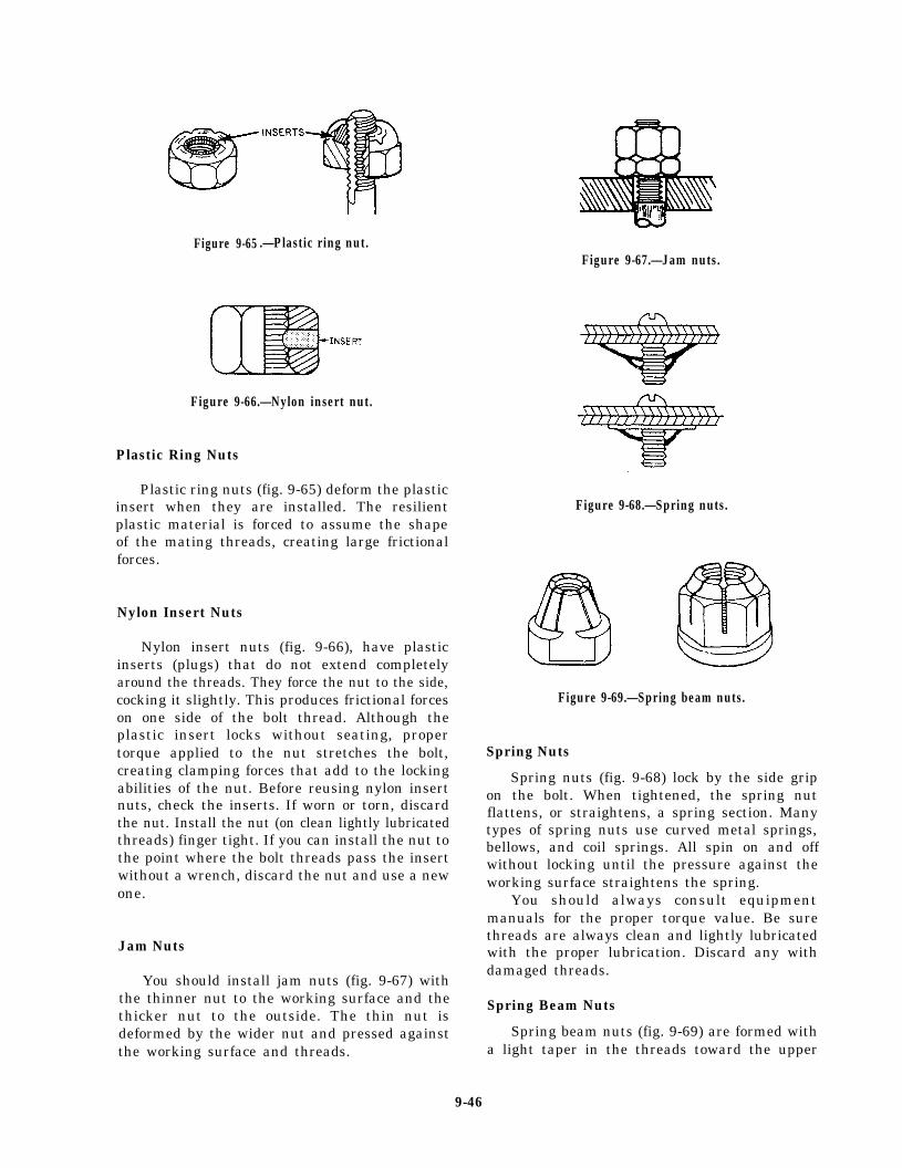
Figure 9-65 .—Plastic ring nut.Figure 9-67.—Jam nuts.
Figure 9-66.—Nylon insert nut.
Plastic Ring Nuts
Plastic ring nuts (fig. 9-65) deform the plasticinsert when they are installed. The resilientplastic material is forced to assume the shapeof the mating threads, creating large frictionalforces.
Nylon Insert Nuts
Nylon insert nuts (fig. 9-66), have plasticinserts (plugs) that do not extend completelyaround the threads. They force the nut to the side,cocking it slightly. This produces frictional forceson one side of the bolt thread. Although theplastic insert locks without seating, propertorque applied to the nut stretches the bolt,creating clamping forces that add to the lockingabilities of the nut. Before reusing nylon insertnuts, check the inserts. If worn or torn, discardthe nut. Install the nut (on clean lightly lubricatedthreads) finger tight. If you can install the nut tothe point where the bolt threads pass the insertwithout a wrench, discard the nut and use a newone.
Jam Nuts
You should install jam nuts (fig. 9-67) withthe thinner nut to the working surface and thethicker nut to the outside. The thin nut isdeformed by the wider nut and pressed againstthe working surface and threads.
Figure 9-68.—Spring nuts.
Figure 9-69.—Spring beam nuts.
Spring Nuts
Spring nuts (fig. 9-68) lock by the side gripon the bolt. When tightened, the spring nutflattens, or straightens, a spring section. Manytypes of spring nuts use curved metal springs,bellows, and coil springs. All spin on and offwithout locking until the pressure against theworking surface straightens the spring.
You should always consult equipmentmanuals for the proper torque value. Be surethreads are always clean and lightly lubricatedwith the proper lubrication. Discard any withdamaged threads.
Spring Beam Nuts
Spring beam nuts (fig. 9-69) are formed witha light taper in the threads toward the upper
9-46
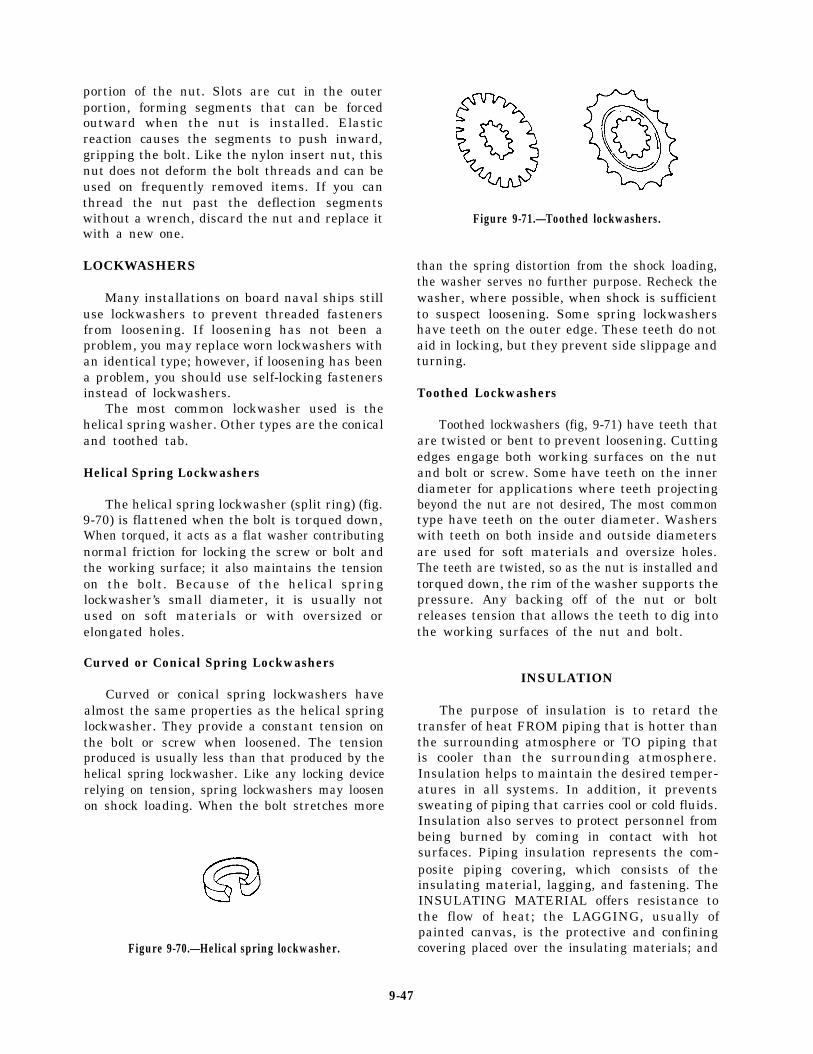
portion of the nut. Slots are cut in the outerportion, forming segments that can be forcedoutward when the nut is installed. Elasticreaction causes the segments to push inward,gripping the bolt. Like the nylon insert nut, thisnut does not deform the bolt threads and can beused on frequently removed items. If you canthread the nut past the deflection segmentswithout a wrench, discard the nut and replace itwith a new one.
LOCKWASHERS
Many installations on board naval ships stilluse lockwashers to prevent threaded fastenersfrom loosening. If loosening has not been aproblem, you may replace worn lockwashers withan identical type; however, if loosening has beena problem, you should use self-locking fastenersinstead of lockwashers.
The most common lockwasher used is thehelical spring washer. Other types are the conicaland toothed tab.
Helical Spring Lockwashers
The helical spring lockwasher (split ring) (fig.9-70) is flattened when the bolt is torqued down,When torqued, it acts as a flat washer contributingnormal friction for locking the screw or bolt andthe working surface; it also maintains the tensionon the bolt. Because of the helical springlockwasher’s small diameter, it is usually notused on soft materials or with oversized orelongated holes.
Curved or Conical Spring Lockwashers
Curved or conical spring lockwashers havealmost the same properties as the helical springlockwasher. They provide a constant tension onthe bolt or screw when loosened. The tensionproduced is usually less than that produced by thehelical spring lockwasher. Like any locking devicerelying on tension, spring lockwashers may loosenon shock loading. When the bolt stretches more
Figure 9-70.—Helical spring lockwasher.
Figure 9-71.—Toothed lockwashers.
than the spring distortion from the shock loading,the washer serves no further purpose. Recheck thewasher, where possible, when shock is sufficientto suspect loosening. Some spring lockwashershave teeth on the outer edge. These teeth do notaid in locking, but they prevent side slippage andturning.
Toothed Lockwashers
Toothed lockwashers (fig, 9-71) have teeth thatare twisted or bent to prevent loosening. Cuttingedges engage both working surfaces on the nutand bolt or screw. Some have teeth on the innerdiameter for applications where teeth projectingbeyond the nut are not desired, The most commontype have teeth on the outer diameter. Washerswith teeth on both inside and outside diametersare used for soft materials and oversize holes.The teeth are twisted, so as the nut is installed andtorqued down, the rim of the washer supports thepressure. Any backing off of the nut or boltreleases tension that allows the teeth to dig intothe working surfaces of the nut and bolt.
INSULATION
The purpose of insulation is to retard thetransfer of heat FROM piping that is hotter thanthe surrounding atmosphere or TO piping thatis cooler than the surrounding atmosphere.Insulation helps to maintain the desired temper-atures in all systems. In addition, it preventssweating of piping that carries cool or cold fluids.Insulation also serves to protect personnel frombeing burned by coming in contact with hotsurfaces. Piping insulation represents the com-posite piping covering, which consists of theinsulating material, lagging, and fastening. TheINSULATING MATERIAL offers resistance tothe flow of heat; the LAGGING, usually ofpainted canvas, is the protective and confiningcovering placed over the insulating materials; and
9-47
the FASTENING attaches the insulating materialto the piping and to the lagging.
Insulation covers a wide range of temper-atures, from the extremely low temperatures ofthe refrigerating plants to the very high temper-atures of the ship’s waste heat boilers. No onematerial could possibly be used to meet all theconditions with the same efficiency.
INSULATION MATERIALS
The following QUALITY REQUIREMENTSfor the various insulating materials are taken intoconsideration by the Navy in the standardizationof these materials:
1. Low heat conductivity2. Noncombustibility3. Lightweight4. Easy molding and installation capability5. Moisture repellant6. Noncorrosive, insoluble, and chemically
inactive7. Composition, structure, and insulating
properties unchanged by temperatures at which it is to be used
8. Once installed, should not cluster, becomelumpy, disintegrate, or build up in massesfrom vibration
9. Verminproof10. Hygienically safe to handle
Insulating material is available in preformedpipe coverings, blocks, batts, blankets, and felts.Refer to NSTM, Chapter 635, “Thermal, Fire,and Acoustic Insulation,” for detailed informa-tion on insulating materials, their application, andsafety precautions.
The insulating cements are comprised of avariety of materials, differing widely amongthemselves as to heat conductivity, weight, andother physical characteristics. Typical of thesevariations are the asbestos substitute cements,diatomaceous cements, and mineral and slag woolcements. These cements are less efficient thanother high-temperature insulating materials, butthey are valuable for patchwork emergency repairsand for covering small irregular surfaces (valves,flanges, joints, and so forth). Additionally, thecements are used for a surface finish over blockor sheet forms of insulation, to seal jointsbetween the blocks, and to provide a smoothfinish over which asbestos substitute or glass clothlagging may be applied.
REMOVABLE INSULATION
Removable insulation will be found on thebleed air systems and waste heat boiler systems.Removable insulation is also installed in thefollowing locations:
. Flange pipe joints adjacent to machineryor equipment that must be broken whenunits are opened for inspection or overhaul
. Valve bonnets of valves larger than 2inches internal pipe size (IPS) that operateat 300 psi and above or at 240°F and above
. All pressure-reducing and pressure-regu-lating valves, pump pressure governors,and strainer bonnets
GENERAL INSULATIONPRECAUTIONS
You should observe the following generalprecautions relative to the application andmaintenance of insulation:
1. Fill and seal all air pockets and cracks.Failure to do this will cause large losses inthe effectiveness of the insulation.
2. Seal the ends of the insulation and taperoff to a smooth, airtight joint. At jointends or other points where insulation isliable to be damaged, use sheet metallagging over the insulation. You shouldcuff flanges and joints with 6-inch lagging.
3. Keep moisture out of all insulation work.Moisture is an enemy of heat insulation justas much as it is in electrical insulation. Anydampness increases the conductivity of allheat-insulating materials.
4. Insulate all hangers and other supports attheir point of contact from the pipe orother unit they are supporting; otherwise,a considerable quantity of heat will be lostvia conduction through the support.
5. Keep sheet metal covering bright andunpainted unless the protective surface hasbeen damaged or has worn off. The radia-tion from bright-bodied and light-coloredobjects is considerably less than fromrough and dark-colored objects.
6. Once installed, heat insulation requirescareful inspection, upkeep, and repair.Replace lagging and insulation removed tomake repairs as carefully as when originally
9-48
installed. When replacing insulation, makecertain that the replacement material is ofthe same type as had been used originally.
7. Insulate all flanges with easily removableforms. These forms are made up as padsof insulating material, wired or bound inplace, and the whole covered with sheetmetal casings, which are in halves.
8. Asbestos control: Inhalation of excessivequantities of asbestos fibre or filler canproduce severe lung damage in the form ofdisabling or fatal fibrosis of the lungs.Asbestos has also been found to be a casualfactor in the development of cancer of themembrane lining the chest and abdomen.Lung damage and disease usually developslowly and often do not become apparentuntil years after the initial exposure. Ifyour plans include a long and healthyNavy retirement, you have no businessdoing asbestos lagging rip-out withoutproper training, protective clothing, and
supervision. Most systems of today’smodern Navy have been purged of asbestosand an asbestos substitute material installedin its place. Some of the older class vesselsmay still have some asbestos insulationinstalled. Use caution when handlinglagging and insulation from these vessels.If in doubt, contact your supervisor andrequest the medical department conduct asurvey of the material in question.
SUMMARY
This chapter has given you general informa-tion on pumps, valves, and piping. It would bea good idea to get some hands-on experienceaboard your ship. Trace various systems out andsee how they are set up. Ask your LPO to explainthe systems and how each part in the systemworks. The key phrase here is ASK QUESTIONS!
9-49