Embed Size (px)
Citation preview

PULSAR® GeneratorOperator’s Manual

Copyright © 2012 Medtronic, Inc. All rights reserved. No part of this publication may be reproduced, transmitted, transcribed, stored in retrieval systems, or translated into any form, or by any means: electronic, mechanical, magnetic, optical, or otherwise, without the prior written permission of Medtronic Advanced Energy, LLC, 180 International Drive, Portsmouth, NH 03801, United States of America.
Disclaimer Medtronic reserves the right to change its products and services at any time to incorporate the latest technological developments. This guide is subject to change without notice.
Trademarks PEAK, PULSAR, and PEAK PlasmaBlade are registered trademarks of Medtronic, Inc.All other trademarks are property of their respective companies.
Only ◆ CAUTION: Federal (USA) law restricts this device to sale by or on the order of a physician.

PULSAR Generator Operator’s Manual i
Table of Contents
Preface ........................................................................................................................ iiiAbout This Manual ................................................................................................................. iii
Conventions Used in This Manual ................................................................................... iiiHelp ................................................................................................................................... iii
Indications ............................................................................................................................... iiiContraindications .................................................................................................................... ivWarnings and Cautions ........................................................................................................... iv
Introduction ................................................................................................................ 1PULSAR Generator ..................................................................................................................1
Electrosurgical Modes .........................................................................................................1Controls, Displays, and Receptacles ...................................................................................2
Symbols .....................................................................................................................................6Front Panel .........................................................................................................................6Back Panel .........................................................................................................................6
Installation .................................................................................................................. 9Initial Inspection .......................................................................................................................9Installation .................................................................................................................................9Optional Wireless Footswitch .................................................................................................10Preliminary Checks .................................................................................................................10Preliminary Functional Testing ...............................................................................................10
Operation .................................................................................................................. 13Preparing for Surgery ..............................................................................................................13
Preparing for Monopolar Surgery .....................................................................................13Activating the Generator .........................................................................................................15
Monopolar Activation .......................................................................................................15
Cleaning and Maintenance ...................................................................................... 19Inspections Required Before Each Use ...................................................................................19Required Annual Inspections ..................................................................................................19Cleaning .................................................................................................................................19Maintenance ............................................................................................................................20Service .....................................................................................................................................20Storage ....................................................................................................................................20Environmental Protection .......................................................................................................20

ii
Troubleshooting ........................................................................................................ 21Errors .......................................................................................................................................21
Error Code Details ............................................................................................................22Non-Recoverable Faults ..........................................................................................................25
Fault Code Details .............................................................................................................26
Glossary .................................................................................................................... 31
Specifications ............................................................................................................ 33PULSAR Generator ................................................................................................................33Output Characteristic Curves ..................................................................................................38
Limited Warranty .................................................................................................... 41
Product Accessories .................................................................................................. 43

PULSAR Generator Operator’s Manual iii
Preface
This manual and the equipment described within are for use only by qualified medical personnel possessing training in the surgical procedures to be performed. This manual is provided as a guide for using the PULSAR® Electrosurgical Generator (Model Number: PS100-100) only.
About This ManualThe PULSAR Generator Operator’s Manual provides detailed information on operating and maintaining the PULSAR Generator.
For information on accessories, refer to the appropriate instructions for use.
Conventions Used in This Manual
▲ WARNING: A warning indicates a hazardous condition that may result in injury or death, if not corrected or avoided.
◆ CAUTION: Alerts you to the possibility of a problem with the device associated with its use or misuse resulting in equipment damage or failure in a procedure, if not corrected or avoided.
■ IMPORTANT: Highlights important information for a particular section.
● NOTE: Points out additional information that may be helpful.
Help
1. Read through the section of the guide specific to the operation you are performing. Refer to the table of contents and index to locate information. A glossary is included to assist you with any unfamiliar terms.
2. See Troubleshooting on page 21 for a list of problems and suggested solutions.
3. For technical support, contact 1-866-777-9400.
IndicationsThe PEAK Surgery System is indicated for cutting and coagulation of soft tissue during General, Plastic and Reconstructive (including but not limited to skin incisions and development of skin flaps), ENT, Gynecologic, Orthopaedic, Arthroscopic, Spinal and Neurological surgical procedures.

iv Preface
ContraindicationsThe PULSAR Generator with PEAK PlasmaBlade™ should not be used on small appendages or body parts, as in finger surgery or circumcision.
Warnings and CautionsThis manual provides instructions for the set up and operation of the PULSAR Generator. The PULSAR Generator, and its accessories, is intended to produce high-frequency electrical energy for the controlled cutting and coagulation of tissue. Electrosurgery has been used safely in many procedures. Physicians should be familiar with the medical literature, complications, and hazards associated with electrosurgery before beginning any electrosurgical procedure. Electrosurgery, if misused, can pose dangers to patients or staff, as well as other equipment. Safe and effective electrosurgery is dependent not only on equipment design, but also on factors under the control of the user, such as surgical training and clinical decision making. The warnings and cautions presented in this manual should be read, understood and followed for safety purposes.
▲ Warnings for Equipment Preparation
• Connect the Generator electrical cord to a properly grounded Hospital Grade receptacle. Do not use extension cords or three-prong to two-prong adapters with the Generator. Improper grounding may result in equipment damage, fire at the receptacle, or injury to the patient or user.
● NOTE: “Use Hospital Grade receptacle for grounding reliability” statement applies to US/North America power cords only.
• To allow for appropriate cooling, the unit should not be installed in a cabinet or similar enclosure. If mounted on a shelf, or near a wall, allow a three-inch clearance around the unit to permit free circulation of air on all sides of the unit. Appropriate cooling is necessary to avoid overheating of the unit.
• Prior to use, inspect the Generator for any defects. Do not use the Generator if it appears to be damaged, as product failure or injury may occur.
• Avoid fluid contact with the accessory cable interface to the PULSAR Generator connector receptacle, because shorting can occur which can damage the accessory connector and/or the Generator receptacle.
• Use only PULSAR Wireless Footswitches because non-PULSAR wireless footswitches will not work with the PULSAR Generator.
• Do not use cords as handles as insulation damage could occur and increase the risk of burns or cause other injury.

PULSAR Generator Operator’s Manual v
▲ Warnings for Accessories
• Prior to use, inspect all accessory devices and the Generator for any defects. Do not use if insulation or connectors are damaged, because product failure or injury may occur.
• Do not reuse, resterilize or reprocess “Single Use Only” labeled accessory devices, because product failure or injury may occur.
• The Monopolar and Patient Return Electrodes each have unique connectors and receptacles. Do not attempt to connect to the improper receptacle because connector damage can occur, which may result in a failure. Ensure all connections are secure before using.
• Verify that the Patient Return Electrode cable is securely connected to the Patient Return Electrode receptacle. If there is an improper connection the PULSAR Generator will not operate as indicated by the impedance sensing feature.
• Do not connect wet connectors to the Generator as this may result in equipment damage, fire at the receptacle, or injury to the patient or user.
• Do not wrap cords around metal objects as this may induce currents that could produce system performance changes, shocks, fires, or injury to the patient or surgical personnel.
• Do not use accessories other than the ones recommended in Product Accessories. Use of other accessories may result in an unintended output and/or injury to patient.
• Use active accessories with rated voltage equal to or greater than that of the Generator’s maximum output voltage.
▲ Warnings for Patient Preparation
• Observe fire precautions at all times. An electrosurgical device may provide an ignition source due to sparking and heating.
• Do not use in the presence of flammable anesthetics or oxidizing gases such as nitrous oxide and oxygen. Do not activate the unit until vapors from alcohol-based skin prepping agents have dissipated. Naturally occurring gases that accumulate in body cavities can also be an ignition source.
• Ensure that all oxygen circuit connections and endotracheal tubes are leak-free before and during electrosurgery use. An oxygen leak can be a possible ignition source.
• Inadvertent patient contact may result in burns. When not in use, place accessory devices in a dry and nonconductive area away from the patient.
• Position the cables for a Monopolar handpiece and the Patient Return Electrode to avoid patient contact to protect against high frequency current paths to the patient, as such contact may result in patient or user injury.
• Do not allow patient contact with grounded metal objects, as such contact may result in patient or user injury.

vi Preface
• Ensure that the footswitch is not inadvertently depressed to prevent the device from being unintentionally activated. Place the footswitch in a location necessitating deliberate action in order to activate the unit.
• Only the primary surgeon using the handpiece should operate the footswitch. Unintentional activation may occur if the footswitch is activated by a separate user, which may result in patient or user injury.
• Ensure that the sound volume on the Generator is adequately adjusted so that the activation tones are clearly heard. The activation tones are intended to alert the user that the device is active. This will help prevent unintended contact with the device which could result in patient or user injury.
• Monopolar devices require a Patient Return Electrode. The Generator must detect proper Patient Return Electrode impedance before output can be active. The impedance is continuously monitored and displayed while in Monopolar Mode. The Generator presents audible and visible alarms if it detects improper impedance with the Patient Return Electrode in Monopolar Mode and will disable Generator output. Refer to the manufacturer’s instructions for application site and placement procedures when applying the Patient Return Electrode. Do not rely entirely on the impedance sensing feature. It can be affected by a damaged (shorted) Patient Return Electrode. It is recommended that the operator verify appropriate placement and contact of the Patient Return Electrode. Inadequate contact of the Patient Return Electrode may result in patient alternate site burns or injury.
• Contact between patient body parts may result in alternate site burns and should be avoided by placing dry towels or drape material between the body parts.
• Do not cut a Patient Return Electrode to reduce size as this could result in high current density patient burns.
• Heat applied by thermal blankets or other sources may be cumulative with heat from the Patient Return Electrode (caused by electrosurgical currents). Choose a Patient Return Electrode site remote from other heat sources to help minimize the risk of patient injury.
• Interference from high frequency surgical equipment may adversely affect the operation of other electronic medical equipment in the operating room. Interference may be resolved or reduced by rearranging the Generator’s cables such that they do not overlap the cables from other equipment, or by using different power outlets or extension cords for the different pieces of equipment.
• Electrodes and probes used with monitoring, stimulating, and imaging devices can provide paths for high frequency currents even if the electrodes or probes are insulated, battery operated, and/or isolated at 50/60 Hz. To reduce the risk of burns, place any such electrode or probe as far away as possible from the electrosurgical site and the Patient Return Electrode.
• Needle monitoring electrodes are not recommended as burns may inadvertently result.
• Monitoring systems incorporating high-frequency current-limiting devices are recommended for use in an electrosurgical site.

PULSAR Generator Operator’s Manual vii
• The active device should not be used near electrocardiograph electrodes as it can cause interference.
▲ Warnings for Active Implants
• The use of electrosurgery in the presence of internal or external active cardiac implants is potentially hazardous. Interference from the electrical current can cause active implants to malfunction. Consult the cardiac implant manufacturer for further information before proceeding with the surgery.
• To minimize the possibility of cardiac implant interference, place the Patient Return Electrode such that the electrosurgical current path is as far as possible from the pacer lead.
▲ Warnings for Use
• During use, a diminished power output may indicate that the Patient Return Electrode connection has been compromised, failure of an electrical lead, active electrode insulation failure or excessive eschar buildup on the active electrode tip. Do not increase the power output before checking for obvious defects or improper connections. Check for effective contact of the Patient Return Electrode to the patient any time that the patient is moved after initial application of the Patient Return Electrode.
• If power levels were increased to compensate diminished performance, it is recommended to reduce power to the original or a lower level upon resumption of use.
• If the system resets due to a power interruption or low voltage, the system will check for effective contact of the Patient Return Electrode, however the user should verify effective contact of the Patient Return Electrode visually prior to resuming electrosurgery.
• Do not use Monopolar electrosurgery on small appendages, such as in finger surgery, as it can cause thrombosis or other unintended injury to tissue proximal to the surgical site.
• Studies have shown that smoke generated during electrosurgery may be harmful to surgical personnel. These studies recommend the use of a surgical mask and adequate ventilation of the smoke using a surgical smoke evacuator or other means.
• Observe all caution and warning notices printed on the unit.
• Operating room staff should never contact the handpiece tip while the Generator is active, as injury may result.
• The tip of a recently activated handpiece may be hot enough to cause patient burns or ignite surgical drapes or other flammable material. When not in use, store the device in an electrically insulated container or holster. Never place or rest a handpiece on the patient.
• The output power selected should be as low as possible for the intended purpose.
• Failure of the high-frequency surgical equipment could result in an unintended increase of output power.

viii Preface
▲ Warnings for Testing or Servicing
• Do not remove the Generator cover due to electrical shock hazard. There are no user serviceable parts inside.
• Never remove or install any parts with power ON, as this may result in potential for electrical shock or injury. Use only Medtronic Advanced Energy approved replacement parts in order to avoid potential equipment damage or injury.
• Avoid contact with the output leads when the Generator is activated as this may result in injury. Periodically inspect the test leads used for the output connections for obvious defects.
• The Generator is not designed to operate for extended periods of continuous output. When testing, it is recommended that duty cycles be limited to 25% with maximum activation times of 10 seconds into a load greater than or equal to 600 ohms. Use for an extended period of time may result in overheating and equipment damage.
◆ Cautions• Federal (USA) law restricts this device to sale by or on the order of a physician.
• The PULSAR Generator should only be used by qualified medical personnel possessing training in the surgical procedures to be performed.
• Prior to initial use of the PEAK Surgery System, ensure that all package inserts, including warnings, cautions, and instructions for use are read and understood.
• When a Monopolar device is connected to the Generator, the Generator will automatically be set to a default setting. The default setting is provided as a convenient starting point from which the user should adjust the settings as needed. Use the lowest power setting possible and the shortest activation time possible to achieve the desired end effect.
• Periodic maintenance should be performed by a hospital qualified biomedical technician or by a qualified Medtronic representative.
• Minimizing operating temperature and extreme thermal cycles will extend the equipment life.
• The heat dissipation capability of the Generator heat sink may be severely impaired by activating the PULSAR Generator in other than a normal operating position. Testing or using the unit in any other position should be avoided.
• The PULSAR Generator is intended for use only with a PEAK PlasmaBlade single-use monopolar disposable device.

PULSAR Generator Operator’s Manual 1
Introduction
PULSAR GeneratorThe PULSAR Generator is one component of the PEAK Surgery System. The Generator provides radio frequency (RF) energy to a disposable Monopolar electrosurgical device. The system is used to perform electrosurgery.
PULSAR Generator Optional PULSAR Wireless Footswitch
Figure 1. PEAK Surgery System
Electrosurgical ModesThe PULSAR Generator operates in the following modes:
Cut Modes
• Low Cut – Precision cutting with some hemostasis and minimal collateral damage
• Medium Cut (Pure Cut) – Precision cutting with increased hemostasis and collateral damage
• High Cut (Blend Mode) – Precision cutting with strong hemostasis
Coagulation Modes Coagulation increases with higher settings.
• Low Coag (Pinpoint)
• High Coag (Spray)
■ IMPORTANT:• Each cut and coagulation mode has multiple power settings available.
• Monopolar device models vary and may not utilize all modes. Available modes for each device are per applicable device’s Instructions For Use.

2 Introduction
Other features of the PULSAR Generator include:
• Proprietary devices developed by Medtronic Advanced Energy to deliver RF energy to the patient. Only PEAK PlasmaBlade devices may be used with the PULSAR Generator.
• Device hand control
• Device footswitch control (infrared wireless footswitch)
• Device default settings recognition
• Monopolar and Bipolar connectors, with only the Monopolar functional
• Connection to Patient Return Electrode and impedance sensing feature
• Color LCD to prompt user for input and to display informational, error, and fault messages
• Audio feedback—activation and alarm tones
Controls, Displays, and ReceptaclesThis section describes each component of the PULSAR Generator and its function. The controls, displays, and receptacle for Monopolar and Bipolar (not functional) devices, Patient Return Electrodes, and the footswitch are located on the front and rear panels of the Generator.
▲ WARNING: Read all warnings and instructions provided with the Generator prior to use.

PULSAR Generator Operator’s Manual 3
Front Panel Layout DescriptionRefer to Figure 2 for a complete front panel illustration. Each display, control, or receptacle is described in more detail below.
POWER BIPOLAR MONOPOLAR PATIENT
PEAK PlasmaBladeTM
Color LCD Screen
Power Indicator
Coag Output Level Adjustment Buttons
Cut Output Level Adjustment Buttons
Power Switch Patient Return Electrode Connector
Monopolar Device Connector
Bipolar Device Connector (not functional)
Figure 2. Front Panel Layout
Power Switch – A black rocker switch that toggles right to turn the PULSAR Generator power on and toggles left to shut the power off.
Power Indicator – LED that illuminates green while the Generator is powered on and turns off when the Generator is powered off.
Bipolar Device Connector – Not Functional
Monopolar Device Connector – A seven-pin circular connector that accepts Monopolar devices.
Patient Return Electrode Connector – A standard two-pin connector that accepts the Patient Return Electrode connector used in Monopolar procedures.
CUT Output Level Adjustment Buttons – Pressing the up button increases the Cut output level by single-integer increments. Pressing the down button decreases the Cut output level by single-integer decrements.
COAG Output Level Adjustment Buttons – Pressing the up button increases the Coag output level by single-integer increments. Pressing the down button decreases the Coag output level by single-integer decrements.

4 Introduction
Color LCD Touch Screen – Used to prompt the user for input and to display informational and fault messages to the user.
CUT Output Level Display – Indicates the Cut output level in single-integer increments from 1 to 10, where 1 is the lowest level and 10 is the highest level. Each device has an embedded chip dictating the Cut settings for that particular device. These settings are described in the Instructions For Use accompanying the device.
COAG Output Level Display – Indicates the Coag output level in single-integer increments. For Monopolar devices, setting 1 is the lowest level and 10 is the highest level. Each device has an embedded chip dictating the Coag settings for that particular device. These settings are described in the Instructions For Use accompanying the device.
Footswitch Connected Indicator – Indicates that the footswitch is connected to the Generator. A green footswitch icon is displayed at the top center of the display when connected.
Patient Return Electrode Indicators:
Single Foil Electrode Indicator – Indicates connection to a Single Foil Patient Return Electrode. The circle will turn green when a Single Foil electrode is properly connected to the Generator. The green circle will turn red when the Generator detects an improper cable connection to the electrode. It does not monitor contact with the patient. Use a Split Foil electrode for contact impedance monitoring. If the circle turns red, the Patient Return Electrode should be inspected and repositioned or replaced to ensure appropriate placement and connection.
Split Foil Electrode Indicator – Indicates the impedance level of the Patient Return Electrode in Monopolar Mode. The bar graph will remain green with proper Patient Return Electrode impedance. The bar graph will turn red when the Generator does not detect proper Patient Return Electrode impedance. If the bar graph turns red, the Patient Return Electrode should be inspected and repositioned or replaced to ensure appropriate placement and connection.

PULSAR Generator Operator’s Manual 5
Back Panel Layout DescriptionRefer to Figure 3 for a complete back panel illustration. Each control, receptacle, or panel is described in more detail below.
ManufacturerMedtronic Advanced Energy LLC180 International DrivePortsmouth, NH 03801, USA
USE 'HOSPITAL GRADE'RECEPTACLE FOR
GROUNDING RELIABILITY
CAUTION: RISK OF
ELECTRICAL SHOCK
PULSAR Generator
PS100-100REF:
SN:
Class I, IEC60601-1100-240VAC 50/60Hz
400Watts
Label P/N: 30-1688 Rev. A
2 x T6.3A100V-240V
DANGER
UL-60601-1IEC 60601-2-2
HF SURGICAL EQUIPMENT
CAN/CSA C22.2 N�. 601. 1
OUTPUT POWERMONOPOLAR:30W/40 OHMS/4MHz120W/600 OHMS/460KHzINT 10s/30s
��U�
Power Entry ModuleEquipotential Ground Connector
Footswitch Connector
Screw-on Access Panel Volume
Control Knob
Figure 3. Back Panel Layout
Power Entry Module – The power entry module combines the connector for the 3-prong, Hospital-Grade power cord with removable enclosure holding two line fuses. Always use fuses of the rating shown in “Mains Input Characteristics” on page 34 of this manual.
NOTE: “Use Hospital Grade receptacle for grounding reliability” statement applies to US/North America power cords only.
Footswitch Connector – A connector that accepts a PULSAR Wireless Footswitch connector.
Screw-On Access Panel – Provides access to the Ethernet port. This port is used for maintenance features that can only be performed by a qualified Medtronic Advanced Energy technician.
Volume Control Knob – Adjusts the volume of the speaker.
Equipotential Ground Connector – Standard connector for connecting common grounds.

6 Introduction
SymbolsThe following symbols are found on the front and back panels of the Generator.
Front Panel
Symbol Description
Defibrillation-proof type CF equipment
RF Isolated - Patient connections are isolated from earth at high frequency
Warning: Dangerous voltage
Power ON - To indicate connection to the mains
Power OFF - To indicate disconnection from the mains
UP button - To increase the output level
DOWN button - To decrease the output level
Consult instructions for use
Back Panel
Symbol Description
Model number
Serial number
Date of manufacture

PULSAR Generator Operator’s Manual 7
Symbol Description
Equipotential ground
Caution, consult accompanying documents
Non-ionizing radiation
Speaker volume control
Footswitch
Explosion risk if used in the presence of flammable anesthetics
Fuse
Separate collection of waste at end of life as required by European Directives. Dispose of in accordance with the applicable country regulation.
Manufacturer

8 Introduction

PULSAR Generator Operator’s Manual 9
Installation
Initial InspectionUnpack the Generator upon receipt and physically inspect it for any obvious damage that may have occurred during shipment. A qualified biomedical engineer or other person thoroughly familiar with electrosurgical devices should perform this inspection.
If the Generator is damaged, call 1-866-777-9400 for assistance.
InstallationThe PULSAR Generator may be placed on a stable surface.
▲ WARNING: The Hospital Grade power cord of the Generator should be connected to a properly polarized and grounded power source whose voltage and frequency characteristics are compatible with those listed on the nameplate of the PULSAR Generator (located on the rear panel of the Generator). Improper grounding may result in equipment damage, fire at the receptacle, or injury to the patient or user.
● NOTE: “Use Hospital Grade receptacle for grounding reliability” statement applies to US/North America power cords only.
▲ WARNING: To allow for appropriate cooling, do not install the Generator in a cabinet or similar enclosure. If mounted on a shelf or near a wall, allow a 3-inch clearance around the Generator to permit free air circulation on all sides. Appropriate cooling is necessary to avoid overheating of the Generator.

10 Installation
Optional Wireless Footswitch
1. If using the optional footswitch, plug the wireless receiver into the footswitch connector of the PULSAR Generator (see Figure 3 on page 5).
2. Turn on the PULSAR Generator and ensure that the wireless receiver’s power-on LED is green, indicating that the receiver is powered on.
Power-On LED Indicator
Figure 4. Wireless Receiver
▲ WARNING: Only the primary surgeon using the handpiece should operate the footswitch. Unintentional activation may occur if the footswitch is activated by a separate user, which may result in patient or user injury.
Refer to the PULSAR Wireless Footswitch Operator’s Manual for detailed product information.
Preliminary ChecksPrior to installing and using the Generator, it is strongly recommended that a qualified maintenance technician ensure proper and safe operation by testing the performance of the Generator. If problems are observed, the Generator should not be used until the problems have been resolved by a qualified technician. Call Medtronic Advanced Energy Customer Service at 1-866-777-9400.
Preliminary Functional TestingPreliminary functional testing should be conducted by a qualified technician or operating room personnel. Personnel conducting this testing should have fully read and understood this manual.
1. Turn on the Generator by pressing the power switch.
2. Verify the following:
• A self-test screen appears indicating that the system is performing a power-on self-test as shown in Figure 5. The software version is also shown at the bottom of the screen. If the self-test screen does not appear, cycle the power and try again. If the same problem continues, call Medtronic Advanced Energy Customer Service at 1-866-777-9400. Do not attempt to use the Generator until the problem has been resolved.

PULSAR Generator Operator’s Manual 11
Figure 5. Front Panel Showing Self-Test Screen
• The Cut activation tone and the Coag activation tone will sound to allow you to verify operation.
The screen will disappear when the self-test is complete. If the self-test is not successful, an alarm tone sounds. A Fault Code appears on the LCD screen and the Generator output is disabled. The alarm tone will sound until the Generator is turned off. In this case, call Medtronic Advanced Energy Customer Service. Do not attempt to use the Generator until the problem has been resolved.
3. If the self-test is successful, verify the following:
• If the Generator is powered on with no devices connected (Monopolar) or with just the Patient Return Electrode connected, the Generator displays the operational screen with small dashes in the settings positions and no mode specified. The front panel showing the operational screen with no devices connected is shown in Figure 6.
Figure 6. Front Panel Showing Operational Screen with No Devices Connected
• If the Generator is powered on with a Monopolar device connected (with or without the Patient Return Electrode connected), the Generator displays the inactive Monopolar screen showing the default output level settings for the device. The front panel showing the Monopolar screen is shown in Figure 7 using a Split Foil Patient Return Electrode.

12 Installation
Figure 7. Front Panel Displaying the Monopolar Screen with Monopolar Device Connected

PULSAR Generator Operator’s Manual 13
Operation
Preparing for Surgery
1. Ensure the power switch is off, and then connect the power cord to a properly grounded and polarized mating power receptacle.
2. Set the power switch to the on position. The green power ON indicator will indicate proper connection to an AC power source. The color LCD on the front panel will illuminate and show a self-test screen. As the Generator goes through its internal self diagnostics, the Generator should respond by:• Sounding the Cut activation tone, and then the Coag activation tone to allow verification;
and• Replacing the self-test screen with an operational screen indicating the completion of
self-test.
3. After the power-on self-tests, the Generator is ready for use.
If the Generator fails to respond as above, it has failed one of its internal tests and must not be used. An alarm tone will sound and a Fault Code will appear on the front panel LCD. The Generator output is disabled. In this case, call Medtronic Advanced Energy Customer Service at 1-866-777-9400. Do not attempt to use the Generator until the problem has been resolved.
Preparing for Monopolar Surgery
1. Connect the Patient Return Electrode to the Patient Return Electrode connector on the front panel of the Generator. Ensure that the Patient Return Electrode is reliably attached to the patient’s body and as close to the operating field as possible.
2. Position the Patient Return Electrode on the patient.
There are two types of Patient Return Electrodes that are compatible with the Generator: Single Foil Electrodes and Split Foil Electrodes.
• Single Foil Electrode – Position the Single Foil Patient Return Electrode on the patient for the lowest impedance. Connection of the Patient Return Electrode cable to the Single Foil electrode will be indicated by a green circle indicator. When using Single Foil electrode types, only the cable connection is monitored by the Generator. Proper contact with the patient is not monitored.
• Split Foil Electrode – Position the Split Foil Patient Return Electrode on the patient for the lowest impedance, as indicated by the orange bar graph. The impedance is continuously monitored and displayed while in Monopolar Mode. The lower the impedance, the more orange bars will be displayed. Position the Patient Return Electrode to maximize the number of orange bars and then press the Monopolar device activation button once (or press the foot petal if a footswitch is being used) to “lock” the impedance.

14 Operation
Once locked, the bar graph color will change from orange to green and all bars should be displayed.
■ IMPORTANT: This feature is only available for Split Foil Patient Return Electrodes.
The Generator presents audible and visible alarms if it detects improper impedance with the Patient Return Electrode in Monopolar Mode and will disable Generator output. Refer to the “Patient Return Electrode Contact Quality Monitor” on page 36 for specifications related to Patient Return Electrode sensing. Refer to the “Errors” on page 21 for the Error Code number displayed and other indicators when the Generator detects improper Patient Return Electrode impedance. Alarms will be presented only for the compatible Patient Return Electrodes specified in “Product Accessories” on page 43.
▲ WARNING: Refer to the manufacturer’s instructions for application site and placement procedures when applying the Patient Return Electrode.
▲ WARNING: Do not depend solely on the impedance indicator for confirmation of good Patient Return Electrode application. Qualified personnel should make the final decision on proper Patient Return Electrode placement.
3. Plug the PEAK PlasmaBlade Monopolar device into the Monopolar connector.
Upon connection, the Generator will alarm if the device is not recognized as a PEAK PlasmaBlade device, if it fails a unit test, or if it has no life expectancy. The Monopolar display will appear as shown in Figure 7. It will also display the default output levels for Cut and Coag. The green indicator in the upper-right corner of the display shows the Patient Return Electrode impedance when using a Split Foil Patient Return Electrode.
▲ WARNING: Always stow unused devices in an electrically insulated location such as a safety holster.
The optional footswitch may be used. If the footswitch is used, plug the wireless receiver into the footswitch connector. While using a footswitch, the output will be delivered via the Monopolar device. The activation button on the device will continue to function while a footswitch is connected to the Generator. When the footswitch is activated,
• the yellow background of the display will brighten when the Cut pedal is pushed.• the blue background of the display will brighten when the Coag pedal is pushed
■ IMPORTANT: Use only the PULSAR Wireless Footswitch.
■ IMPORTANT: Monopolar devices require a Patient Return Electrode. The Generator must detect proper Patient Return Electrode impedance before the Generator output can be active.
If the Monopolar Mode is not already selected as shown in Figure 7, choose the Monopolar Mode of operation by pressing the Cut or Coag button on the monopolar device or pressing the Cut or Coag foot pedal. Monopolar Modes include Cut and Coag. The mode word “Cut” appears on the left half of the display. The mode word “Coag” appears on the right half of the display.

PULSAR Generator Operator’s Manual 15
The default output levels for Cut and Coag are provided for convenience. The user must deter-mine the preferred settings, and set the level by pressing the UP or DOWN buttons next to the output level on the display. Output levels are displayed in single-integer increments. Disposable Device Instructions for Use will indicate the power associated with each level.
■ IMPORTANT: The output level settings cannot be adjusted while the Generator is activated.
4. The Generator is now ready.
Refer to “Activating the Generator” below.Figure 8 shows an example of the front panel display when the Generator is ready for use in Monopolar surgery.
▲WARNING: Always keep unused, active electrodes away from the patient.
Figure 8. Front Panel when Ready for Monopolar Surgery
Activating the Generator
Monopolar ActivationIf the Generator is not already set up, follow the Monopolar set-up procedure to prepare the Generator for Monopolar operation.
1. Place the Monopolar device in the desired position in the surgical field.
2. Connect the Patient Return Electrode and follow the manufacturer’s Instructions for Use.
3. To activate the system, depress the Cut or Coag button on the handpiece, or depress the Cut or Coag pedal on the footswitch.
Use as low a voltage and power as possible
16 Operation
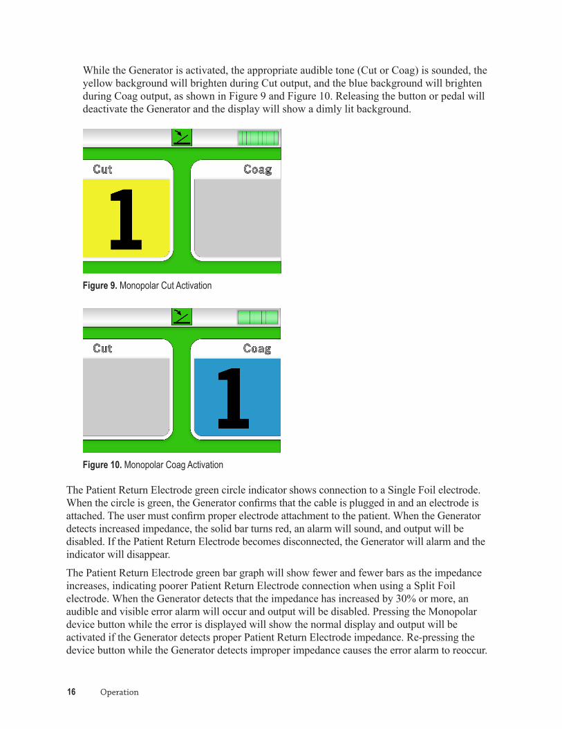
While the Generator is activated, the appropriate audible tone (Cut or Coag) is sounded, the yellow background will brighten during Cut output, and the blue background will brighten during Coag output, as shown in Figure 9 and Figure 10. Releasing the button or pedal will deactivate the Generator and the display will show a dimly lit background.
Figure 9. Monopolar Cut Activation
Figure 10. Monopolar Coag Activation
The Patient Return Electrode green circle indicator shows connection to a Single Foil electrode. When the circle is green, the Generator confirms that the cable is plugged in and an electrode is attached. The user must confirm proper electrode attachment to the patient. When the Generator detects increased impedance, the solid bar turns red, an alarm will sound, and output will be disabled. If the Patient Return Electrode becomes disconnected, the Generator will alarm and the indicator will disappear.
The Patient Return Electrode green bar graph will show fewer and fewer bars as the impedance increases, indicating poorer Patient Return Electrode connection when using a Split Foil electrode. When the Generator detects that the impedance has increased by 30% or more, an audible and visible error alarm will occur and output will be disabled. Pressing the Monopolar device button while the error is displayed will show the normal display and output will be activated if the Generator detects proper Patient Return Electrode impedance. Re-pressing the device button while the Generator detects improper impedance causes the error alarm to reoccur.

PULSAR Generator Operator’s Manual 17
Normally, the error display will disappear after 5 seconds (without re-pressing the device button), showing the normal display if the Generator detects proper Patient Return Electrode impedance. If the Generator does not detect proper impedance after the error display disappears, the bar graph will turn red as shown in Figure 11 and will remain red until proper impedance is detected.
Figure 11. Monopolar Improper Locked Impedance
You may have to reapply or readjust the Patient Return Electrode in order for the Generator to detect proper Patient Return Electrode impedance. Once proper impedance is detected, the indicator will turn green.
If you are not able to adjust the Patient Return Electrode sufficiently to detect proper Patient Return Electrode impedance, unplug the patient return connector and plug it back in. This will unlock the impedance and the bar graph will turn orange. Repeat section “Preparing for Monopolar Surgery” on page 13, step 2 (split foil electrode) to lock the impedance and continue with the surgery.
The Generator presents audible and visible alarms if the Generator detects improper impedance with the Patient Return Electrode in Monopolar Mode and will disable Generator output. Refer to the “Patient Return Electrode Contact Quality Monitor” on page 36 for specifications related to Patient Return Electrode sensing. Refer to “Errors” on page 21 for the Error Code number displayed and other indicators while the Generator detects improper Patient Return Electrode impedance. Refer to the manufacturer’s instructions for application site and placement procedures when applying the Patient Return Electrode.
4. When the surgical procedure is completed, turn off the Generator and disconnect the Monopolar device, footswitch, and Patient Return Electrode.
5. Check the functionality of the implanted devices immediately after the surgical procedure is complete.

18 Operation

PULSAR Generator Operator’s Manual 19
Cleaning and Maintenance
This section contains information for ordinary cleaning and maintenance of the PULSAR Generator. While the Generator has been designed and manufactured to high industry standards, periodic inspection and performance testing must be performed by a qualified biomedical technician for safe and effective operation.
Inspections Required Before Each Use
1. Visually inspect the Generator for physical damage. Report damage to Medtronic Advanced Energy or your biomedical department. Do not use the Generator if it is damaged.
2. Visually inspect the power cord and plug for physical damage. Replace the cord if the insulation has been breached. Do not use the Generator if the cord or plug has been damaged and has not yet been replaced.
Required Annual Inspections
1. Inspect the tightness of the power plug and volume control knob. If these components are loose, they must be replaced with Medtronic Advanced Energy approved components.
2. Inspect the mating, cleanliness, and absence of damage to the patient connectors. Do not use the Generator if the connectors are damaged.
3. Inspect for accumulation of lint or debris within the Generator or fan vents. Do not use the Generator if lint or debris has accumulated and has not been cleared.
Cleaning
▲ WARNING: Electric shock hazard. Always unplug the Generator from the wall outlet prior to cleaning.
The Generator is not sterilizable.
1. Clean the front display, cover, and cord with a mild detergent or mild disinfecting solution and damp cloth. It is recommended that non-flammable agents be used for cleaning and disinfection whenever possible. If flammable agents are used for cleaning, disinfecting, or as solvents, they should be allowed to evaporate before surgery.
◆ CAUTION: Do not allow fluids to enter the chassis. Do not use alcohol, caustic, corrosive, or abrasive materials on the front display, cover, and cord, as they may cause damage to the equipment. Medtronic Advanced Energy recommends following hospital procedures for cleaning the outside of the Generator after each patient.

20 Cleaning and Maintenance
Refer to the PULSAR Wireless Footswitch Operator’s Manual for detailed cleaning instructions for the footswitch and receiver.
MaintenanceThe PULSAR Generator must be performance tested by a hospital qualified biomedical technician at least every year. Follow your hospital’s procedures for periodic performance verification of electrosurgical generators. Medtronic Advanced Energy recommends the following checks:
• Power Output verification for each mode of operation
• RF Leakage
• AC Leakage
• AC Ground Integrity
ServiceThe Ethernet port provided on the rear panel is used for the following service features, which can be performed by a qualified Medtronic Advanced Energy technician only:
• To reprogram set-up parameters.
• To download the event history log, which contains information on errors and faults.
StorageThe Generator must be thoroughly checked by a qualified biomedical engineer if it has been stored for longer than 6 months.
Allow the Generator to remain at room temperature for at least 1 hour if it has been stored at extreme temperatures. Refer to “Storage Parameters” on page 33 for the limits for storing the PULSAR Generator.
Environmental ProtectionRetain the shipping container and packing material in the event that the Generator needs to be returned for repair or service. At the end of the equipment’s life, dispose of it in accordance with your local regulations. The materials in the generator include aluminum, steel, copper, thermoplastics, and electronic components.

PULSAR Generator Operator’s Manual 21
Troubleshooting
This section identifies the possible error and fault conditions and offers common solutions for correcting malfunctions and responding to alarms.
The PULSAR Generator has been designed and manufactured at the highest possible standards. In the rare event that the Generator fails, it has several self-diagnostic routines to aid in troubleshooting the problem. If the software detects a problem, an error code or fault code is displayed on the screen, and the Generator is disabled. The Generator will remain disabled until the detected problem is corrected. The self-diagnostic routines are only an aid for qualified technicians, and are not a substitute for evaluation of a problem by a qualified technician.
▲ WARNING: Electric shock hazard. Always unplug the Generator from the wall outlet prior to opening the cover for servicing. There are no user-serviceable parts inside the Generator. The PULSAR Generator should only be serviced by a Medtronic Advanced Energy trained technician.
ErrorsThe PULSAR Generator includes automatic self-diagnostics. If the diagnostics detect a condition that can be corrected by the operator, the system displays an error code, sounds an alarm tone, and deactivates the Generator’s output. Correcting the error will enable the Generator’s output.
Most error codes result from conditions in accessories attached to the Generator. The following table lists the error codes and describes the condition.
Error Code Description
E1 Cut or Coag switch on Monopolar device may be stuck in the ON position.
E2 Cut or Coag footpedal switch may be stuck in the ON position.
E3 Patient Return Electrode has poor connection.
E4 Generator output error.
E5 Monopolar device has reached end of life.
E6 Not in use.
E7 Monopolar device is not recognized as a PEAK PlasmaBlade Monopolar device or failed testing.
E8 Not in use.
E9 Monopolar output activated without Patient Return Electrode connected.

22 Troubleshooting
Error Code Description
E10 Not in use.
E11 Patient Return Electrode was connected, but connection was lost.
Error Code DetailsA detailed description of the cause of each error is provided below, along with steps to follow. Figure 12 shows an example of an Error screen.
Figure 12. Error Code E1
Error Code E1Cut or Coag switch on electrosurgical device may be stuck in ON position.
Cause Solution
Monopolar device has Cut or Coag button stuck in the ON position when the device is connected. The Error Code is displayed and the alarm will sound once.
1. Ensure that the handpiece is not in contact with the patient.2. Disconnect and reconnect the Monopolar handpiece.3. If the Error Code reappears, turn the Generator power OFF
and then turn the power ON again.4. If the problem persists, replace the Monopolar handpiece
and repeat this procedure.5. If the Error Code reappears, record the number and contact
Medtronic Advanced Energy Customer Service. Do not use the Generator.

PULSAR Generator Operator’s Manual 23
Error Code E2Cut or Coag foot pedal switch may be stuck in the ON position.
Cause Solution
Footswitch has Cut or Coag pedal switch stuck in the ON position when the footswitch is connected. The Error Code is displayed and the alarm will sound once.
1. Ensure that the handpiece is not in contact with the patient.2. Disconnect and reconnect the footswitch.3. If the Error Code reappears, turn the Generator power OFF
and then turn the power ON again.4. If the problem persists, replace the footswitch and repeat
this procedure.5. If the Error Code reappears, record the number and contact
Medtronic Advanced Energy Customer Service. Do not use the Generator.
Error Code E3Patient Return Electrode has poor connection.
Cause Solution
The Error Code is displayed when the impedance is out of range. The Error Code is displayed for 5 seconds and the alarm will sound once. The Patient Return Electrode impedance icon will turn red and stay red as long as the impedance is out of range. The Patient Return Electrode impedance is continuously checked.
1. Follow the manufacturer’s instructions for Patient Return Electrode placement.
2. Verify that the Patient Return Electrode is connected to the Generator and is making proper contact with the patient.
3. If the impedance icon remains red, replace the Patient Return Electrode and connector.
4. Repeat preparations of Monopolar surgery. Position the Patient Return Electrode making contact for lowest impedance.
5. If the Error Code reappears, record the number and contact Medtronic Advanced Energy Customer Service. Do not use the Generator.

24 Troubleshooting
Error Code E4Generator output error.
Cause Solution
Measurements of the output voltage are being made while the Generator has active output. If these measurements are outside the normal range, the output will be disabled. The Error Code is displayed and the alarm will sound once.
1. Pressing the footswitch or handpiece button again will clear this screen and reactivate output if the error is no longer detected. The handpiece should not be in contact with the patient while this is done.
2. If the Error Code reappears, replace the handpiece.3. If the Error Code reappears, disconnect the handpiece and
the Patient Return Electrode. Turn the Generator power OFF and then turn the power ON again. Reconnect the handpiece and Patient Return Electrode and try again.
4. If the Error Code reappears, record the number and contact Medtronic Advanced Energy Customer Service. Do not use the Generator.
Error Code E5Monopolar device has reached end of life.
Cause Solution
For safety reasons, each device has a limited active life span. If the time is exceeded, then the Error Code is displayed and the alarm will sound once.
1. Replace the Monopolar device.2. The Error Code screen will disappear if the device is
recognized, tested, and has a life expectancy. 3. If the Error Code reappears, record the number and contact
Medtronic Advanced Energy Customer Service. Do not use the Generator.
Error Code E7Monopolar device is not recognized as a PEAK PlasmaBlade Monopolar device or has failed testing.
Cause Solution
The Monopolar device is connected to the Generator and it is not recognized as a PEAK PlasmaBlade device or it has failed testing. The Error Code is displayed and the alarm will sound once.
1. Replace the Monopolar device. The Error Code screen will disappear if the device is recognized, tested, and has a life expectancy.
2. If the Error Code reappears, record the number and contact Medtronic Advanced Energy Customer Service. Do not use the Generator.

PULSAR Generator Operator’s Manual 25
Error Code E9Monopolar output activated without Patient Return Electrode connected.
Cause Solution
The Generator has detected that a Patient Return Electrode is not connected when a button or the footswitch is pressed in Monopolar activation mode.
1. Apply a Patient Return Electrode to the patient and try again.
2. If the Error Code reappears, turn the Generator power OFF and then turn the power ON again.
3. If the Error Code reappears, record the number and contact Medtronic Advanced Energy Customer Service. Do not use the Generator.
Error Code E11Patient Return Electrode was connected, but connection was lost.
Cause Solution
The Patient Return Electrode or its cable has become disconnected.
1. Disconnect the Patient Return Electrode cable and reconnect it to the Generator. The impedance icon should confirm proper connection. Verify the Patient Return Electrode is making proper contact with the patient.
2. If the Error Code reappears, replace the Patient Return Electrode cable and connector and retry.
3. If the Error Code reappears, record the number and contact Medtronic Advanced Energy Customer Service. Do not use the Generator.
Non-Recoverable FaultsThe PULSAR Generator includes automatic self-diagnostics. If the diagnostics detect a non-recoverable fault, the system displays a fault code, sounds an audible tone, and deactivates the Generator’s output. All non-recoverable faults indicate a possible problem with the equipment. Power must be turned off and then back on before operation can continue. If the Self-Test does not successfully complete, refer the equipment to Service Personnel.
Most non-recoverable fault codes result from faults in the Generator. The following table lists the non-recoverable fault codes.
Non-Recoverable Fault Code Description
F1 Internal temperature of the Generator has exceeded the limit.
F2 Self-test fault.
F3 Watchdog Processor has detected a Controller Processor failure.

26 Troubleshooting
Non-Recoverable Fault Code Description
F4 Watchdog Monitor has detected a Watchdog Processor failure.
F5 RF Module Monitor has detected a RF Module failure.
F6 RF Module communication with the Controller Processor has failed.
F7 RF Module not calibrated or calibration was lost.
F8 Power Supply voltage is too low.
F9 Power Supply undercurrent.
Fault Code DetailsA detailed description of the cause of each fault code is provided below, along with steps to follow. Figure 13 shows an example of a Fault screen.
Figure 13. Fault Code F1
Fault Code F1Internal temperature of the Generator has exceeded the limit.
Cause Solution
Internal temperature exceeded limit while turned ON. The Fault Code is displayed and the alarm will sound once.
1. Leave the Generator ON with the internal fan running to cool the Generator. Do not use the Generator until it has cooled sufficiently. Once the Generator has cooled, the Fault Code will no longer be displayed.
2. If the Fault Code reappears, record the number and contact Medtronic Advanced Energy Customer Service. Do not use the Generator.

PULSAR Generator Operator’s Manual 27
Fault Code F2Self-test fault.
Cause Solution
Self-test diagnostics are run when the Generator is powered ON. This Fault Code indicates that one or more of the self-tests have failed. The individual self-test that failed will be recorded in the Generator’s data flash for retrieval during maintenance. The Fault Code is displayed and the alarm will sound continuously.
1. Turn the Generator power OFF and then turn the power ON again. Do not press buttons or activate handpieces during the self-test.
2. If the Fault Code reappears, disconnect the handpiece and Patient Return Electrode. Turn the Generator power OFF and then turn the power ON again.
3. If the Fault Code reappears, record the number and contact Medtronic Advanced Energy Customer Service. Do not use the Generator.
Fault Code F3Watchdog Processor has detected a Controller Processor failure.
Cause Solution
The Watchdog processor has detected that the Controller processor has failed. The Watchdog processor will hold the Controller processor in reset and the alarm will sound continuously until the Generator is turned off.
1. Turn the Generator power OFF and then turn the power ON again. Reconnect the handpiece and Patient Return Electrode and try again.
2. If the Fault Code reappears, record the number and contact Medtronic Advanced Energy Customer Service. Do not use the Generator.
Fault Code F4Watchdog Monitor has detected a Watchdog Processor failure.
Cause Solution
The Controller processor has detected that the Watchdog processor has failed. The Fault Code is displayed and the alarm will sound continuously until the Generator is turned off.
1. Turn the Generator power OFF and then turn the power ON again. Reconnect the handpiece and Patient Return Electrode and try again.
2. If the Fault Code reappears, record the number and contact Medtronic Advanced Energy Customer Service. Do not use the Generator.

28 Troubleshooting
Fault Code F5RF Module Monitor has detected a RF Module failure.
Cause Solution
The Controller processor has detected that the RF Output module has failed. The Fault Code is displayed and the alarm will sound once.
1. Turn the Generator power OFF and then turn the power ON again. Reconnect the handpiece and Patient Return Electrode and try again.
2. If the Fault Code reappears, record the number and contact Medtronic Advanced Energy Customer Service. Do not use the Generator.
Fault Code F6RF Module communication with the Controller Processor has failed.
Cause Solution
The Controller processor has detected that the RF Module communication is corrupt. The Fault Code is displayed and the alarm will sound once.
1. Turn the Generator power OFF and then turn the power ON again. Reconnect the handpiece and Patient Return Electrode and try again.
2. If the Fault Code reappears, record the number and contact Medtronic Advanced Energy Customer Service. Do not use the Generator.
Fault Code F7RF Module not calibrated or calibration was lost.
Cause Solution
The RF Module has detected that it is not calibrated or calibration values have been lost. The Fault Code is displayed and the alarm will sound continuously until the Generator is turned off.
1. Turn the Generator power OFF and then turn the power ON again. Reconnect the handpiece and Patient Return Electrode and try again.
2. If the Fault Code reappears, record the number and contact Medtronic Advanced Energy Customer Service. Do not use the Generator.

PULSAR Generator Operator’s Manual 29
Fault Code F8Power supply voltage is too low.
Cause Solution
Power supply processor has detected that the input voltage to the RF amplifier module is too low. The Fault Code is displayed and the alarm will sound continuously until the Generator is turned off.
1. Turn the Generator power OFF and then turn the power ON again. Reconnect the handpiece and Patient Return Electrode and try again.
2. If the Fault Code reappears, record the number and contact Medtronic Advanced Energy Customer Service. Do not use the Generator.
Fault Code F9Power supply undercurrent.
Cause Solution
Power supply processor has detected that the sensed output current is too low. The Fault Code is displayed and the alarm will sound once.
1. Turn the Generator power OFF and then turn the power ON again. Reconnect the handpiece and Patient Return Electrode and try again.
2. If the Fault Code reappears, record the number and contact Medtronic Advanced Energy Customer Service. Do not use the Generator.

30 Troubleshooting

PULSAR Generator Operator’s Manual 31
Glossary
This section provides definitions of terms relating to electrosurgery. The information below is provided as a convenience and should not be interpreted as an authoritative discussion of the subject.
active electrode The electrode or electrode assembly at which the electrosurgical effect is intended. It usually has a small contact surface area and provides a high current density to achieve the desired surgical effect.
blend A modified cut waveform incorporating some off-time, thus allowing tissue to cool, and providing varying degrees of hemostasis.
coagulation The clotting of blood or dehydration of tissue with no cutting effect. Electrosurgical coagulation often incorporates intermittent bursts of high-voltage, low-current electricity.
cutting Occurs when intense sparks focus the energy and vaporize the tissue. It results from high current density in the tissue causing cellular fluid to burst into steam and disrupt the structure. Voltage is low and current flow is high. In order to induce a cutting effect in human tissue, voltage must exceed 200 Vp.
desiccation A procedure where a small amount of surface tissue is dried out by placing the active electrode in contact with the tissue. Desiccation differs from fulguration in that peak voltage is lower resulting in the inability of the current to arc through air to tissue. Direct contact between electrode and tissue is required. See fulguration.
dispersive electrode The electrode at which no electrosurgical effect is intended or desired. It is usually large in area in order to provide a low current density so that no electrosurgical effect occurs at that site. It is also known as a patient plate, patient pad, plate electrode, return electrode, neutral electrode, inactive electrode. It is sometimes (inaccurately) referred to as a grounding plate.
disposable accessory An electrosurgical accessory, such as active electrodes, handles, dispersive electrodes, etc. It is not intended to be used more than once.

32 Glossary
duty cycle The proportion of time (expressed in percentage) that a current or device is on versus off. Duty cycle may be used when referring to current waveforms that are repetitive. Thus high-frequency current would be on using a shorter period of time than a low-frequency current. Duty cycle is also used in reference to electrical components or equipment. For example, some equipment is designed to be used continuously, that is, with a duty cycle rating of 100%, while other equipment may be rated for intermittent use, that is less than 100% duty cycle. Most ESU’s are designed to be used intermittently. Typically, they are rated for 50% duty cycles. Use of any equipment beyond it’s duty cycle rating may result in premature failure.
electrosurgery (surgical diathermy)
The generation and delivery of radio frequency current between an active electrode and a dispersive electrode for the purposes of dehydration of tissue. Electrosurgery also includes cutting or vaporizing (tissue explosion). In contrast to electrocautery, the electric current actually passes through the patient.
electrosurgical accessory
Equipment used in conjunction with the electrosurgical generator to accomplish electrosurgery. These include, but are not limited to footswitch, cable, dispersive electrode, and active electrode.
fulguration (spray technique)
Coagulating tissue or blood by means of radio frequency electric arcs. In contrast to desiccation, the active electrode is not in good electrical contact with the tissue, and arcs jump from the electrode to the tissue.
impedance (measured in ohms)
Total opposition, both resistive and reactive, a circuit offers to the flow of alternating current at a given frequency.
mode (operating)
Each of the distinct ways in which the electrosurgical unit can be operated with electrosurgical output, for example, monopolar cutting, monopolar coagulation, monopolar blended, monopolar spray (fulguration).
monopolar The traditional form of electrosurgical circuit, which uses an active electrode to apply the therapeutic current to the surgical site, and a dispersive electrode (patient plate) to return the current to the ESU.
power The rate at which energy is produced or consumed. Power is equal to voltage times current, or resistance times current squared. The unit of measure of power is the watt.

PULSAR Generator Operator’s Manual 33
Specifications
PULSAR GeneratorAll specifications are nominal and are within ±20% of a stated value at room temperature (77°F/25°C) and a nominal input power voltage. All specifications are subject to change without notice.
General Classification: IEC 60601-1, Class IType: CFInternal Design: Solid stateOutput Configuration: Isolated (RF Floating)Cooling: Forced air (fan)Designed to Meet: UL60601-1; IEC 60601-1, 60601-1-4, 60601-1-2, 60601-2-2; CAN/
CSA C22.2 NO. 601.1.
Dimensions and Weight Width: 13.8 in (35 cm)Length: 15.2 in (38.5 cm)Height: 7.1 in (18 cm)Weight: <26.5 lb (12 kg)
Operating Parameters Temperature: 10°C to 40°CHumidity: 30% to 75% relative humidity, non-condensingDegree of Protection Against Ingress of Water:
IPX0
Storage Parameters Temperature: –20°C to 60°C
Humidity: Non-condensing relative humidityShipping Conditions for Packaged Unit:
–40°C to 70°C; 10–100% relative humidity, including condensation

34 Specifications
Audio SpecificationsThe audio levels stated below are for activation tones (Cut and Coag) and alarm tones (return electrode and system alarms) at a distance of one meter. Alarm tones meet the requirements for IEC 60601-2-2.
Activation Tone Alarm Tone
Volume: 45 to 65 dB, adjustable 70 ±5 dB, not adjustable
Frequency: Mono Cut: 1.5 kHzMono Coag: 600 Hz
2 kHz for 0.5 seconds1 kHz for 0.5 seconds
Duration: Continuous while the Generator is activated
2 seconds for Errors, continuous for Faults
Mains Input Characteristics
FrequencyHz
Mains Voltage (V) Mains Current (A) Fuses*
Nominal Minimum Maximum Maximum
50–60 115/230 100 240 5.3 T6.3A
* Fuses are Type T, High Breaking
Low Frequency (50/60Hz) Leakage Current
• Earth leakage current in normal condition <5 mA
• Earth leakage current in single-fault condition <10 mA
• Enclosure (touch) leakage current in normal condition <100 µA
• Enclosure (touch) leakage current in single fault condition <500 µA
• Patient leakage current in normal condition <10 µA
• Patient leakage current in single fault condition <50 µA
PULSAR Generator Operator’s Manual 35
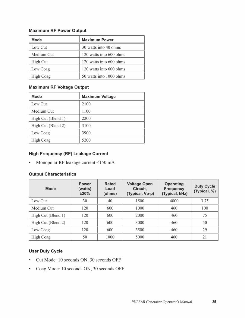
Maximum RF Power Output
Mode Maximum Power
Low Cut 30 watts into 40 ohmsMedium Cut 120 watts into 600 ohmsHigh Cut 120 watts into 600 ohmsLow Coag 120 watts into 600 ohmsHigh Coag 50 watts into 1000 ohms
Maximum RF Voltage Output
Mode Maximum Voltage
Low Cut 2100Medium Cut 1100High Cut (Blend 1) 2200High Cut (Blend 2) 3100Low Coag 3900High Coag 5200
High Frequency (RF) Leakage Current
• Monopolar RF leakage current <150 mA
Output Characteristics
ModePower(watts)±20%
Rated Load
(ohms)
Voltage Open Circuit,
(Typical, Vp-p)
Operating Frequency
(Typical, kHz)
Duty Cycle (Typical, %)
Low Cut 30 40 1500 4000 3.75Medium Cut 120 600 1000 460 100High Cut (Blend 1) 120 600 2000 460 75High Cut (Blend 2) 120 600 3000 460 50Low Coag 120 600 3500 460 29High Coag 50 1000 5000 460 21
User Duty Cycle
• Cut Mode: 10 seconds ON, 30 seconds OFF
• Coag Mode: 10 seconds ON, 30 seconds OFF

36 Specifications
Patient Return Electrode Contact Quality Monitor
The system presents audible and visible alarms when it senses no Patient Return Electrode.
Cord Fault Single Foil: Continuous measurement: 20 ±5 Ohms in resistance will cause an alarm. When the alarm condition exists, the system deactivates output power.
Split Foil: Continuous measurement: Once the system establishes the split foil electrode impedance, an increase of 30% or more will cause an alarm. When the alarm condition exists, the system deactivates output power.
Electromagnetic Compatibility
The PULSAR Generator conforms to electromagnetic compatibility standard EN/IEC 60601-1-2.
Guidance and Manufacturer’s Declaration – Electromagnetic Emissions
The PULSAR Generator is intended for use in the electromagnetic environment specified below. The customer or user of the PULSAR Generator should assure that it is used in such an environment.
Emissions Test Compliance Electromagnetic Environment – Guidance
RF emissions - RadiatedCISPR11
Group 1Class A
The PULSAR Generator must emit electromagnetic energy in order to perform its intended function. Nearby electronic equipment may be affected.
RF emissions - ConductedCISPR11
Group 1Class A
The PULSAR Generator is suitable for use in all establishments other than domestic, and may be used in domestic establishments and those directly connected to public low-voltage power supply network that supplies buildings used for domestic purposes, provided the following warning is heeded.
▲WARNING: This equipment/system is intended for use by healthcare professionals only. This equipment/system may cause radio interference or may disrupt the operation of nearby equipment. It may be necessary to take mitigation measures, such as re-orienting or relocating the PULSAR Generator or shielding the location.
Harmonic emissions IEC 61000-3-2
Complies
Voltage fluctuations / flicker emissions IEC 61000-3-3
Complies

PULSAR Generator Operator’s Manual 37
Guidance and Manufacturer’s Declaration –Electromagnetic Immunity
The PULSAR Generator is intended for use in the electromagnetic environment specified below. The customer or user of the PULSAR Generator should assure that it is used in such an environment.
Immunity Test IEC 60601 Test Level Compliance Level
Electromagnetic Environment Guidance
Electrostatic discharge (ESD) EN 61000-4-2
±6 kV contact±8 kV air
Complies Floors should be wood, concrete, or ceramic tile. If floors are covered with synthetic material, the relative humidity should be at least 30%.
Radiated RFIEC 61000-4-3
10 V/m80 Mhz to 2.5 GHz
Complies
Electrical fast transient/burst IEC 61000-4-4
±2 kV for power supply lines±1 kV for input/output lines
Complies Mains power quality should be that of a typical commercial or hospital environment.
Surge IEC 61000-4-5
±1 kV line(s) to line(s)±2 kV line(s) to earth
Complies Mains power quality should be that of a typical commercial or hospital environment.
Conducted RF IEC 61000-4-6
3 Vrms150 kHz to 80 MHz in ISM bands
Complies
Power frequency (50/60 Hz) magnetic fieldIEC 61000-4-8
3 A/m Complies Power frequency magnetic fields should be at levels characteristic of a typical location in a typical commercial or hospital environment.
Voltage dips, short interruptions, and voltage variations on power supply input lines IEC 61000-4-11
<5% UT
(>95% dip in UT ) for 0.5 cycle40% UT
(60% dip in UT ) for 5 cycles70% UT
(30% dip in UT ) for 25 cycles<5% UT
(>95% dip in UT ) for 5 sec
Complies Mains power quality should be that of a typical commercial or hospital environment. If the user of the PULSAR Generator requires continued operation during power mains interruptions, it is recommended that the PULSAR Generator be powered from an uninterruptible power supply or a battery.
NOTE: UT is the AC mains voltage prior to application of the test level.
Other Specifications Power Cord: Generators have a power entry connector to allow connection with a US
Hospital Grade power cord or an EU plug power cord. Units accept 100–240 VAC at a frequency of 50/60 Hz, fused at 6.3 amps.
Display Size: 6.4 in diagonal (3.8 in tall x 5.2 in wide)

38 Specifications
Output Characteristic Curves
0
5
10
15
20
25
30
35
40
0 20 40 100 200 500 1000 2000
POW
ER (w
atts
)
LOAD (ohms)
Output Power Low Cut
Figure 14. Output Power vs Impedance for Low Cut
-
20
40
60
80
100
120
140
0 200 400 600 800 1000 1200 1400 1600 1800 2000
POW
ER (w
atts
)
LOAD (ohms)
Output Power Medium Cut
Figure 15. Output Power vs Impedance for Medium Cut

PULSAR Generator Operator’s Manual 39
-
20
40
60
80
100
120
140
0 200 400 600 800 1000 1200 1400 1600 1800 2000
POW
ER (w
atts
)
LOAD (ohms)
Output Power High Cut (BLEND 1)
Figure 16. Output Power vs Impedance for High Cut (Blend 1)
-
20
40
60
80
100
120
0 200 400 600 800 1000 1200 1400 1600 1800 2000
POW
ER (w
atts
)
LOAD (ohms)
Output Power High Cut (BLEND 2)
Figure 17. Output Power vs Impedance for High Cut (Blend 2)
40 Specifications
-
20
40
60
80
100
120
140
0 200 400 600 800 1000 1200 1400 1600 1800 2000
POW
ER (w
atts
)
LOAD (ohms)
Output Power Low Coag
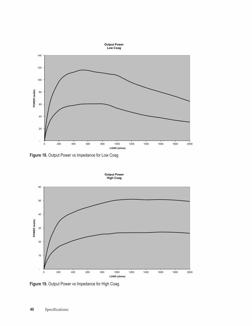
Figure 18. Output Power vs Impedance for Low Coag
-
10
20
30
40
50
60
0 200 400 600 800 1000 1200 1400 1600 1800 2000
POW
ER (w
atts
)
LOAD (ohms)
Output Power High Coag
Figure 19. Output Power vs Impedance for High Coag

PULSAR Generator Operator’s Manual 41
Limited Warranty
Medtronic Advanced Energy LLC warrants the PULSAR Generator against defects in materials or workmanship under normal use and preventive maintenance for the respective warranty periods shown below. Medtronic Advanced Energy will repair or replace the unit without charge, at its option, of any product, or part thereof, which has been returned to Medtronic Advanced Energy LLC or its Distributor within the applicable time period shown below. This warranty does not apply to any product or part that has been adversely affected due to use with devices manufactured or distributed by parties not authorized by Medtronic Advanced Energy LLC; repaired or altered outside Medtronic Advanced Energy’s factory; subjected to improper use, negligence or accident or not used in accordance with the instructions provided in this manual. Standard hospital preventive maintenance procedures should be followed and performed by qualified biomedical service personnel and are not covered in the warranty.
• Medtronic Advanced Energy’s products are warranted for the following periods after delivery to the original purchaser:
• PULSAR Generator - One (1) Year, Parts and Labor
• PULSAR Wireless Footswitch - One (1) Year, Parts and Labor

42 Limited Warranty

PULSAR Generator Operator’s Manual 43
Product Accessories
The following accessories are compatible for use with the PULSAR Generator. Only Medtronic Advanced Energy recommended accessories should be used with the Generator.
• PEAK PlasmaBlade Monopolar Devices
• PULSAR Wireless Footswitch
• Standard Patient Return Electrode or Pad
• Single Foil Electrodes – Valleylab Standard PolyHesive™ II E7506
• Split Foil Electrodes – Adult REM Valleylab PolyHesive II E7507


70-10-1434 Rev A April 2013
Manufacturer Medtronic Advanced Energy LLC 180 International Drive Portsmouth, NH 03801 USA
Tel: 866-777-9400 Fax: 866-222-0900
www.medtronicadvancedenergy.com