Embed Size (px)
Citation preview

R
A HILTI GROUP COMPANY
PUB131010
UNIRAC RMDESIGN & ENGINEERING
R
A HILTI GROUP COMPANY
UNIRAC RMDESIGN & ENGINEERING
R
A HILTI GROUP COMPANY
P-0
UNIRAC RMDESIGN & ENGINEERING
MANUALS
• MANAGING THE PROJECT• QUICK START GUIDE (OVERALL INSTALLATION/ASSEMBLY STEPS)• FIELD ADJUSTMENTS (SOLVING PROBLEMS)• DESIGN & ENGINEERING• INSTALLATION INSPECTION & MAINTENANCE

R
A HILTI GROUP COMPANY
1. Introduction: What is RM?2. Site Visit
Physical CharacteristicsCommon Low Slope Roofing MaterialQuality of the roof structural supportObstructionsShadowing / ShadingCricketsParapetsVibration CreatorsDrainageAestheticsAccessibilityWiringAir movement
3. Code ComplianceModel Building CodeModel Building Code (continued)Listing AuthoritiesLocal code / AHJ approvalCode Compliance HierarchyOtherElectrical code
4. Determine layoutModule dimensionsRow spacing based on bay dimensionSetbacksRoof ObstructionsRoof Considerations
5. Project Structural Design ConsiderationsEngineering variables and loadsEvaluation of the loadsPressure to point loadsApplying the Engineering to the structural design
6. Seismic ConsiderationsUnattached arraysUnattached arrays (continued)Unattached arrays (continued)Attached arraysAttached arrays (continued)Attachment locations
7. Calculating applicable wind loads, applicable standards8. Prescriptive Structural Design Tables
Assumptions/limitationsInterior/Exterior ModulesLoad Sharing RegionsTable A & BTable C & DTable E & FTable G & H
9. Ballast DistributionBallast Distribution (continued)Supplemental baysSupplemental bays (continued)Max point load: how to calculate
10. U-BuilderIntroductionU-Builder user guide
11. Electrical DesignBonding and groundingWire managementMicro-inverter mountingDesign enginneer of recordAHJ has final say
12. AppendicesSystem specificationSystem components - part numbersAssembled viewAssembled view (continued)Component view & discriptionsComponent - Ballast BayComponent - Module ClipComponent - Seismic AttachmentComponent - Roof PadComponent - Balast Blocks
TABLE OF CONTENTS:
P-00
P-1P-1P-2P-3P-3P-4P-4P-5P-5P-5P-5P-6P-6P-7P-7P-8P-9P-10P-11P-12P-13P-14P-14P-15P-15P-16P-17P-17P-17P-18P-19P-20P-21P-22P-23P-24P-25P-26P-27P-28P-29
P-30 P-31P-31P-32P-33P-34P-35P-36P-37P-38P-39P-40P-41P-42P-43P-43P-44P-45P-45P-46P-47P-48P-48P-49P-49P-50P-51P-52P-53P-54P-55P-56P-57P-58
R
A HILTI GROUP COMPANY
1. INTRODUCTION: WHAT IS RM?
P-1
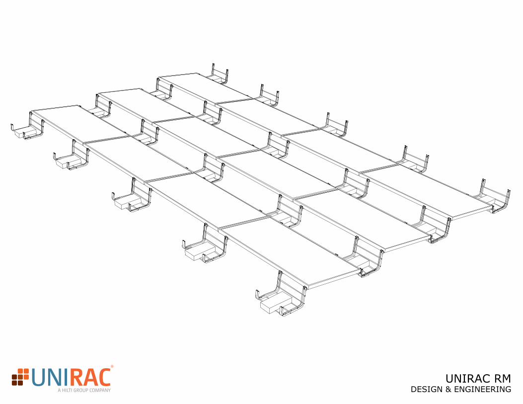
The Unirac Roof Mount (RM) system is a PV module racking system that introduces the power of simplicity to the low-slope roof solar industry, an intuitive design inspired by installers nationwide. The RM system is conducive to the use of ballast, or weight, as the method for overcoming uplift forces to minimize or eliminate attachments to the roof structure. This document presents information that informs the PV array designer of the important design and engineering aspects of the RM system. Additionally, the information contained herein serves the jurisdictional plan checker’s purposes.
2. SITE VISIT
As part of the planning process for your PV project it is recommended that a thorough site visit be done to ensure that the site is well understood in order to mitigate any surprises. During the site visit there are several items of interest that should be examined and noted.
R
A HILTI GROUP COMPANY
P-2
2.1 PHYSICAL CHARACTERISTICS
Note: Directional notes apply only to installation sites in the Northern Hemisphere.
In general, a perfectly designed PV system will face true, due south, have minimal shading, and is be positioned to harvest the most sunlight and therefore produce the maximum amount of electricity. You must evaluate the following physical characteristics for the site where a PV system can potentially be installed:
— Compass readings (direction)— Dimensions— Pitch (slope) — Shade causing objects
Even though maximum output usually occurs with the PV system facing due south, certain site characteristics may prevent you from adhering to this ideal installation method. Successful PV systems can be installed facing within a range of due east going south to due west.
The horizontal angle (direction) the array is facing is referred to as the azimuth. The azimuth determines the time of day the PV system can produce the greatest amount of energy. A system that faces east produces most of its energy during the morning, while a west-facing system produces more in the afternoon.
The direction a PV system could face can be measured with a compass. This gives a magnetic direction. In most locations, the true direction and the magnetic direction are not the same. The difference between the two is called magnetic declination. The magnetic declination of the array varies from location to location, but you can easily modify magnetic direction to get true direction. One way to compute this is through the NOAA (National Oceanic and Atmospheric Administration) National Geophysical Data Center website (http://www.ngdc.noaa.gov/geomagmodels/struts/calcDeclination).
During the site evaluation, consider various possible locations that would be suitable to mount the PV system. For each of these locations, record the dimensions and pitch (slope) of the mounting surface. Also make note of any objects that could potentially shade the area or obstruct the installation. Some objects of concern include vent pipes, trees, portions of buildings, and air-conditioning units (See sections 1d and 1e, below).
R
A HILTI GROUP COMPANY
2.2 COMMON LOW SLOPE ROOFING MATERIALS
P-3
Typically, low-slope roof assemblies are composed of three interrelated components: the roof membrane, roof insulation, and the roof deck. The roof system is defined as the roof membrane (including surfacing) and the roof insulation. The roof assembly is defined as the roof deck, along with the roof membrane and roof insulation. Low-slope roofs are often referred to as flat roofs. Roof assemblies with a pitch (slope) of less than 3:12 are considered low-slope roofs. The most common roofing membrane materials are the following:
— PVC roofing system (Polyvinyl Chloride)
— EPDM roofing system (Elastomeric compound synthesized from ethylene, propylene, and a small amount
of diene monomer)
— TPO roofing system (Thermoplastic olefin)
— Built-up roofing system (BUR consists of multiple layers of roofing felt (ply sheets) applied in shingle fashion with a waterproofing material (interply adhesive) to form a 2-, 3-, 4-, or 5-ply layer membrane over which a coating, surfacing (gravel), or cap sheet is applied to protect the membrane)
2.3 QUALITY OF THE ROOF STRUCTURAL SUPPORT
When the PV system will be mounted on a building, the structural support capacity of the building needs to be evaluated by a Registered Design Professional of Responsible Charge. This registered design professional must evaluate the structural members of the roof to determine if it is capable of resisting all of the loads that may be experienced with the additional PV structure on top. Because the PV system may be attached to structural members such as rafters (never to roof decking alone), be sure to note the location of structural members, their condition and the distance between members.
For older buildings, this structural evaluation is very important as many of these buildings have rafters made of 2 x 4’s, a much weaker rafter member than newer buildings use. This could be an issue later when considering the feasibility of an array designed to attach to such a roof (see section on Roof Attachments).
R
A HILTI GROUP COMPANY
P-4
2.4 OBSTRUCTIONS
Roofs can have a variety of roof obstruction which includes HVAC equipment, roof vents, etc. These need to be considered in the array layout with regards to shading, equipment access and to ensure that the array doesn’t impact the normal operations of this equipment. There may be requirements as far as a minimum setback distance from mechanical equipment so be sure to consult your local authority to determine what considerations need to be taken. Also, discuss with the building owner if roof top equipment needs a specific amount of room for maintenance operations.
2.5 SHADOWING/SHADING
Avoid shade at all costs in your installation since even just a small amount of shade can eliminate most of the electrical output. In most cases, shading on one small area of one module impacts the output of the entire array. While some technologies and alternative methods exist for mitigating the effects of shade on the PV system, they can be expensive and are often unproven in their effectiveness. Be conservative and assume no PV production can occur if any portion of the array is shaded. There are tools available to help with the shading evaluation at the site, such as Solar Pathfinder and even an application for an iPhone called Sun Tracker.
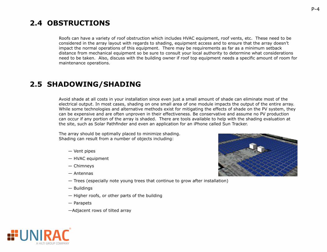
The array should be optimally placed to minimize shading. Shading can result from a number of objects including:
— Vent pipes
— HVAC equipment
— Chimneys
— Antennas
— Trees (especially note young trees that continue to grow after installation)
— Buildings
— Higher roofs, or other parts of the building
— Parapets
—Adjacent rows of tilted array
R
A HILTI GROUP COMPANY
P-5
2.6 CRICKETS
Roof crickets are shallow valleys or ridges built into the roof that are designed to divert water on a roof and direct it to the designated drain areas. The RM racking system is extremely flexible and able to accommodate roof crickets up to 3.5 degrees.
2.7 PARAPETS
A parapet is a barrier which is an extension of the wall at the edge of a roof, terrace, balcony, or other structure. Where extending above a roof, it may simply be the portion of an exterior wall that continues above the line of the roof surface, or may be a continuation of a vertical feature beneath the roof such as a fire wall or party wall. Parapets are primarily used as guard rails and to prevent the spread of fires.
The wind tunnel study performed on the RM system requires that the wind pressure coefficients increase when there are parapets. Please take this into account when planning for your system. The U-Builder design tool takes this into account and will give you the appropriate values.
2.8 VIBRATION CREATORS
There may be mechanical equipment on the roof that could cause vibrations to occur and impact the performance of the racking system. If there is equipment like this on your building it is recommended that you regularly check on the PV array to ensure that it is in the same structural condition as the day it was installed.
2.9 DRAINAGE
Roofs are designed such that they run off water in certain directions to provide optimal water drainage. The biggest concern with regards to roof drainage and a PV array is to make sure that the racking does not restrict the drainage of a roof. Another concern is to make sure that crickets aren’t so deep such that it impacts how the racking rests on the roof. We recommend that the racking system is in full contact with the roof.
R
A HILTI GROUP COMPANY
P-6
2.10 AESTHETICS
The appearance of the PV system is very important to most system owners, the neighborhood, and sometimes homeowner associations (HOA). Typically, flush mounted systems have a more acceptable aesthetic appearance.In some locations, the HOA may have guidelines for PV. Conversely, some states have legislation stating that PV cannot be prohibited based upon aesthetics alone.
2.11 ACCESSIBILITY
You must evaluate the accessibility of the site for construction equipment and needs. Ask the following questions when evaluating a site:
• Is there specialized equipment required to access the site? Such as, the roof is only assessable by crane.
• Is there road access near the site? Will equipment have to be carried a long distance by hand?
•Can the installation be done safely? Is specialized safety equipment required?
• In the case of a roof mount, how high is the installation area off of the ground?
• Where will be a good staging area to unload and sometimes prep equipment?
• Do you have all of the permissions necessary, such as adjacent property owners?
The answers may signal an increased installation cost, but not necessarily that PV is unfeasible.
R
A HILTI GROUP COMPANY
P-7
2.12 WIRING
Even if you design the PV system in an aesthetically acceptable manner, other aspects of the installation can detract from its appearance, such as wiring. During the site evaluation, note the location of the main electrical service, as well as electrical sub-panels. A grid-tied PV array must be connected to the main panel, main service, or a sub-panel.
During the design phase, you will address the method of running conduit from the PV system. For example, on a roof mount, should the wiring method be surface mounting the conduit? Is there a path to run the conduit through an attic or garage? What materials are required to complete the wiring method? Locations where the wiring enters the building will require metal conduit.
The following examples of wiring methods for a roof mount are not a comprehensive list. You may choose different products to accomplish the ideal wiring method for the project at hand.
• Array on roof and inverter in garage: Mount a junction box directly to the roof. Run LFMC (liquid tight flexible metal conduit) FMC (flexible metal conduit) or EMT (electrical metallic tubing) through the attic. Drop the conduit through the ceiling of the garage.
• Array on roof and inverter on wall directly below the array: Mount a junction box directly on the roof, over the soffit. Drop EMT directly down from the junction box and run along the wall.
2.13 AIR MOVEMENT
You should also note the prevailing wind direction if possible during your site visit. Wind direction can be used to your advantage to mitigate high temperatures that reduce voltage output. More air flow under the array means less heat and higher overall efficiency for the PV system. During the design phase, you may choose to maximize the gap between the modules and the surface on which the array is mounted. The RM system has a fixed geometry so it has a fixed height off of the roof.
It is also recommended that you have someone evaluate the roof to determine if there are any special wind considerations to take into account. For example there could be roof equipment or building geometry that could cause a channeling effect on the roof. If a condition like this exists it would be wise to keep the PV array out of this type of area or address this by adding additional support or possibly attachments.
R
A HILTI GROUP COMPANY
P-8
3. CODE COMPLIANCE
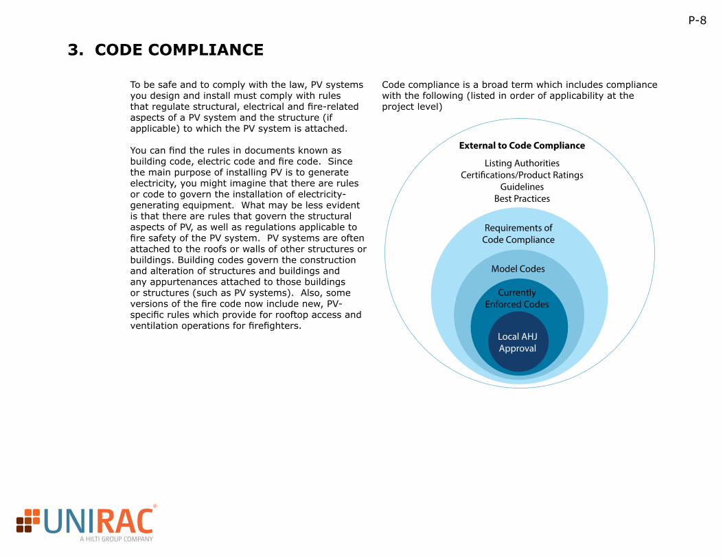
To be safe and to comply with the law, PV systems you design and install must comply with rules that regulate structural, electrical and fire-related aspects of a PV system and the structure (if applicable) to which the PV system is attached.
You can find the rules in documents known as building code, electric code and fire code. Since the main purpose of installing PV is to generate electricity, you might imagine that there are rules or code to govern the installation of electricity-generating equipment. What may be less evident is that there are rules that govern the structural aspects of PV, as well as regulations applicable to fire safety of the PV system. PV systems are often attached to the roofs or walls of other structures or buildings. Building codes govern the construction and alteration of structures and buildings and any appurtenances attached to those buildings or structures (such as PV systems). Also, some versions of the fire code now include new, PV-specific rules which provide for rooftop access and ventilation operations for firefighters.
Code compliance is a broad term which includes compliance with the following (listed in order of applicability at the project level)
External to Code Compliance
Listing AuthoritiesCerti�cations/Product Ratings
GuidelinesBest Practices
Requirements ofCode Compliance
Model Codes
CurrentlyEnforced Codes
Local AHJApproval
R
A HILTI GROUP COMPANY
P-9
3.1 MODEL BUILDING CODE
Model code consists of code documents issued by the governing bodies of the construction, fire safety and electric industries. These model codes act as a master reference for states and municipalities in terms of code compliance.
While model code is the standard for our industry, it does not include language specific to PV systems. You, along with your local AHJ, must interpret code relating to structures and electrical systems and apply those laws to your PV design.
Examples of model code include:
• International Building Code (IBC): This model building code has been adopted in most jurisdictions in the U.S. and is published by the International Code Council (ICC). The International Building Code is what all solar structures should be evaluated against.
• National Electric Code (NEC): This model code contains a subset of specifics for residential buildings and is applicable to residential one- and two-family dwellings. It is published by the National Fire Protection Association (NFPA)
• International Fire Code (IFC): This model code covers the minimum safety requirements for electrical installations and fire safety concerns. It is published by the ICC.
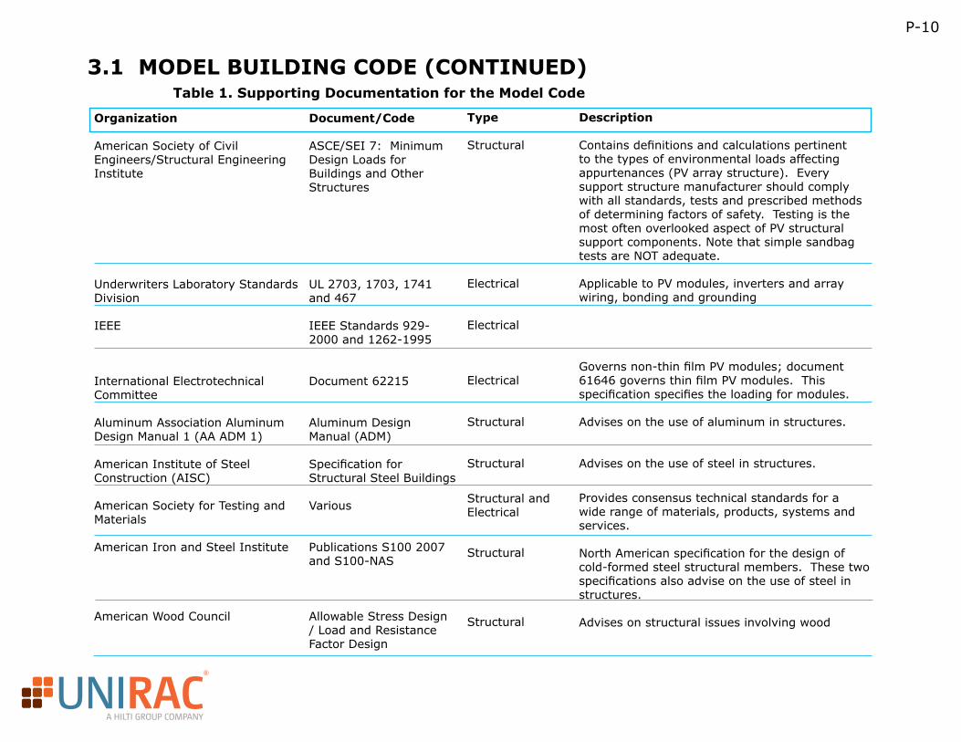
The model code often invokes other external documents to offer further clarification of the code. This external document might include more specific standards, test reports and design manuals. Some examples of such detailed documentation that you may need to reference are shown in the table below.Note: The document listing below is not meant to be exhaustive and other documents may apply to a particular installation depending on the installation location or project type.
R
A HILTI GROUP COMPANY
P-10
3.1 MODEL BUILDING CODE (CONTINUED)Table 1. Supporting Documentation for the Model Code
Organization
American Society of Civil Engineers/Structural Engineering Institute
Underwriters Laboratory Standards Division
IEEE
International Electrotechnical Committee
Aluminum Association Aluminum Design Manual 1 (AA ADM 1)
American Institute of Steel Construction (AISC)
American Society for Testing and Materials
American Iron and Steel Institute
American Wood Council
Document/Code
ASCE/SEI 7: Minimum Design Loads for Buildings and Other Structures
UL 2703, 1703, 1741 and 467
IEEE Standards 929-2000 and 1262-1995
Document 62215
Aluminum Design Manual (ADM)
Specification for Structural Steel Buildings
Various
Publications S100 2007 and S100-NAS
Allowable Stress Design / Load and Resistance Factor Design
Type
Structural
Electrical
Electrical
Electrical
Structural
Structural
Structural and Electrical
Structural
Structural
Description Contains definitions and calculations pertinent to the types of environmental loads affecting appurtenances (PV array structure). Every support structure manufacturer should comply with all standards, tests and prescribed methods of determining factors of safety. Testing is the most often overlooked aspect of PV structural support components. Note that simple sandbag tests are NOT adequate.
Applicable to PV modules, inverters and array wiring, bonding and grounding
Governs non-thin film PV modules; document 61646 governs thin film PV modules. This specification specifies the loading for modules.
Advises on the use of aluminum in structures.
Advises on the use of steel in structures.
Provides consensus technical standards for a wide range of materials, products, systems and services.
North American specification for the design of cold-formed steel structural members. These two specifications also advise on the use of steel in structures.
Advises on structural issues involving wood
R
A HILTI GROUP COMPANY
P-11
3.2 LISTING AUTHORITIES
Listing authorities actually evaluate a product for compliance with a model code. Many products can be considered to be code-compliant that are not listed; however, a product listed with these authorities has been vetted against the standards of the model code by top experts in the field. These listing authorities cooperate with and abide by the regulatory agencies governing such fields by law.
• International Code Council Evaluation Service (ICC-ES): This division of the ICC evaluates building products for compliance to code.
• National Fire Protection Association (NFPA): Develops minimum fire safety standards in the U.S. The main NFPA document used in the PV industry is the NEC.
• International Association of Plumbing and Mechanical Officials (IAPMO):
• Underwriters Laboratory (UL): Performs product certifications and writes standards for safety. It is an independent, for-profit product safety certification organization.
• *UL does not have power of law in the U.S. A product can pass UL certification without being UL listed. Their listing doesn’t mean a product will perform, it merely means that the product will not present a hazard.
• Community Europe (CE): Performs testing of equipment in the European Economic Area. The CE mark certifies that a product meets EU safety requirements. By affixing the CE marking to a product, the manufacturer – on his sole responsibility – declares that it meets EU safety and health and environmental requirements.
• ETL: The ETL certification mark is from the independent laboratory at Intertek. It is proof of product compliance (electrical, gas and other safety standards) to North American safety standards, including UL, ANSI, CSA, ASTM and NFPA standards.
• Canadian Construction Materials Centre (CCMC): Offers evaluation services for all types of innovative building construction materials, products, systems and services. CCMC evaluations are supported by the latest technical research and expertise and are based on the requirements of the National Building Code of Canada or Provincial/Territorial Building Codes.
R
A HILTI GROUP COMPANY
P-12
3.3 LOCAL CODE/AHJ APPROVAL
When a local jurisdiction adopts a building code, it adopts a specific edition of the model code. This may not be the most current edition of the model code issued.
They may adopt the model code verbatim as the building, electric or fire codes for their jurisdiction, or they may adopt a modified edition of the code with amendments or additional rules. In some cases, the additional requirements and exemptions are issued as a separate document or, the jurisdiction may create a merged code, incorporating all of the local revisions. In still other cases, the jurisdiction may print, under its own title, their own version of the code. An example of this final scenario is the California Building Code.
Most importantly, the local Authority Having Jurisdiction (AHJ) knows what codes have been adopted for your site and can tell you what codes will apply to the installation. The very first thing a contractor should do to be code compliant is to talk to the local AHJ before starting a final design. The local AHJ ultimately holds the authority over permitting, inspecting and approving your work, so consulting with them is essential. The question to be answered by the AHJ is, “What codes cover my installation site, and what is the edition/year of that code?”
R
A HILTI GROUP COMPANY
P-13
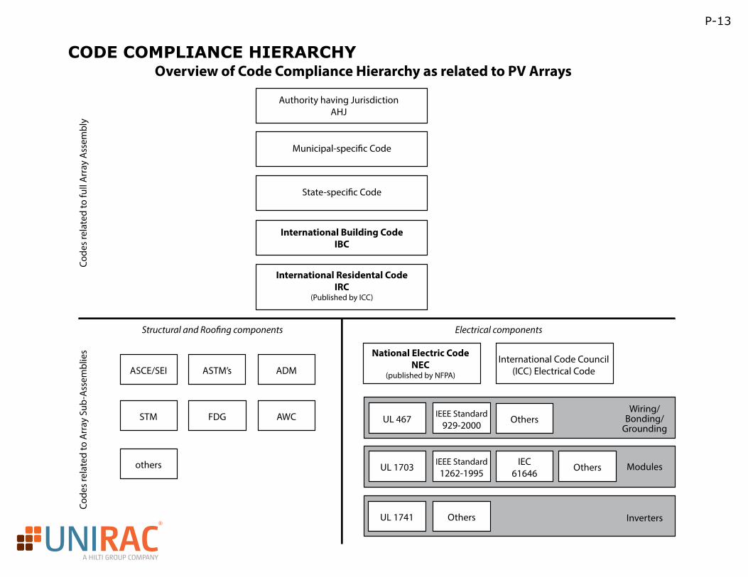
CODE COMPLIANCE HIERARCHYOverview of Code Compliance Hierarchy as related to PV Arrays
Authority having JurisdictionAHJ
Municipal-speci�c Code
State-speci�c Code
International Building CodeIBC
International Residental CodeIRC
(Published by ICC)
National Electric CodeNEC
(published by NFPA)
International Code Council(ICC) Electrical Code
Code
s re
late
d to
full
Arr
ay A
ssem
bly
Code
s re
late
d to
Arr
ay S
ub-A
ssem
blie
s
Structural and Roo�ng components
ASCE/SEI ASTM’s ADM
FDG AWCSTM
others
Electrical components
InvertersUL 1741 Others
UL 467
UL 1703
IEEE Standard929-2000 Others
IEEE Standard1262-1995
IEC61646
Others
Wiring/Bonding/
Grounding
Modules
R
A HILTI GROUP COMPANY
P-14
3.4 OTHER
Various organizations in the field also issue guidelines of their own. These guides sometimes contain valuable information, but remember they are only guidelines, and not the letter of the law. Organizations with guidelines you might be aware of are: Sheet Metal and Air Conditioning Contractors’ National Association (SMACNA), Asphalt Roofing Manufacturing Association (ARMA), National Roofing Contractors Association (NRCA).
Keep in mind that every top level code is comprised of many pieces and parts that contribute to compliance requirements. Once you know the applicable code and the edition being enforced in your installation area, you can easily source the information to succeed in being compliant.
3.5 ELECTRICAL CODE
While the manufacturer’s installation instructions generally take precedence over other requirements, many local or state jurisdictions have additional requirements beyond those found in the National Electrical Code (NEC). When a PV system is utility owned and operated, the installation is technically outside the scope of the NEC. But what exactly is a utility? This is a very important distinction because the NEC generally requires the use of equipment listed to UL standards. However, if a PV installation is not subject to the NEC, the use of equipment designed to meet other standards, such as those established by the IEC, may be permitted.
Since the standards to which PV equipment must conform vary by context, as do the applicable codes, it is incumbent on designers and installers to understand the regulatory context within which they are working. This regulatory context influences what equipment and installation practices are likely to be acceptable to the AHJ and the interconnected utility. Because there is no universal set of requirements, system designers and installers must be proactive about communicating with AHJs and utilities to streamline project permitting, inspection and commissioning.
R
A HILTI GROUP COMPANY
P-15
4. DETERMINE LAYOUT
After the aforementioned factors have been considered with your site, you’ll want to determine the layout of your project by taking the following items into consideration. This will help you ensure that you’ll fit the PV array into your designated area in the most effective manner.
All modules in a RM installation are racked in a landscape orientation, and feature a nominal 10-degree fixed tilt.In order to calculate the amount of roof space required for an installation, you need to determine East-West and North-South array dimensions.
We recommend a ¼” gap between the panels in the east-west direction so be sure to include that when calculating the total width of the array.
4.1 MODULE DIMENSIONS
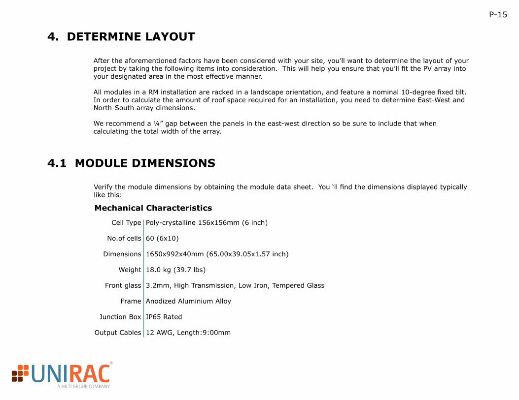
Verify the module dimensions by obtaining the module data sheet. You ‘ll find the dimensions displayed typically like this:
Mechanical Characteristics
Poly-crystalline 156x156mm (6 inch)
60 (6x10)
1650x992x40mm (65.00x39.05x1.57 inch)
18.0 kg (39.7 lbs)
3.2mm, High Transmission, Low Iron, Tempered Glass
Anodized Aluminium Alloy
IP65 Rated
12 AWG, Length:9:00mm
Cell Type
No.of cells
Dimensions
Weight
Front glass
Frame
Junction Box
Output Cables
R
A HILTI GROUP COMPANY
P-16
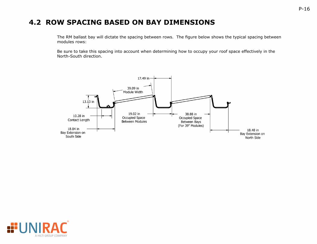
4.2 ROW SPACING BASED ON BAY DIMENSIONS
The RM ballast bay will dictate the spacing between rows. The figure below shows the typical spacing between modules rows:
Be sure to take this spacing into account when determining how to occupy your roof space effectively in the North-South direction.
R
A HILTI GROUP COMPANY
P-17
4.3 SETBACKS
A setbacks is how far from the edge of the roof or roof obstruction your array will be installed. The proprietary wind study conducted on the RM product requires a minimum of 3 feet from the outermost point of the array to the edge of the roof. Your local building code may require a different setback so be sure to check with your local AHJ to see what’s required. There are also requirements as far as setbacks from certain roof equipment. Be sure to evaluate what those may be depending on the type of equipment on your roof.
4.4 ROOF OBSTRUCTIONS
The RM product is design to be “modular” in order to easily accommodate unique layouts caused by roof obstructions. There are often vents, mechanical equipment and skylights on flat roofs that govern the layout of an array. With these roof obstructions there are things to consider such as setbacks from the equipment as well as access ways which are typical spelled out in the respective building or fire codes. Note that when an array has many “breaks” in it to accommodate obstructions that you are not getting the most efficient use of the racking and can often cause the required ballast to increase based on the results from the wind study.
4.5 ROOF CONSIDERATIONS
The RM system may be installed on the following roofing materials: EPDM, TPO, PVC, Modified Bitumen and Built-Up Roofs. For Tar and Gravel roof applications contact Unirac for guidance.
Other factors to consider for an RM project include:• Flat roof applications with slopes from 0 – 5 degrees (up to 3 degrees for high seismic areas)• Minimum clearance to roof edge: 3 ft (including parapet width). For installations within this setback please contact Unirac for guidance.• Building Height: 10 ft to 60 ft. For buildings 60 ft to 100 ft please contact either Unirac or a professional engineer for guidance.• Clearance for roof objects: the height of the obstruction should be the clearance distance from the array.
R
A HILTI GROUP COMPANY
P-18
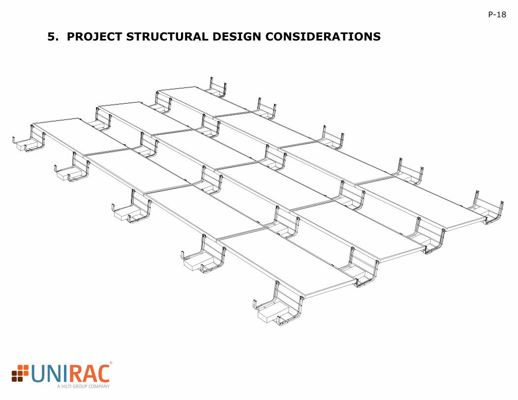
5. PROJECT STRUCTURAL DESIGN CONSIDERATIONS
R
A HILTI GROUP COMPANY
P-19
5.1 ENGINEERING VARIABLES AND LOADS
These are some of the design parameters involved in a structural evaluation and application:
• Basic or Design Wind Speed: Often referred to as a “3-second gust”, this is the highest sustained wind gust over a 3 second period having a probability of 1 in 50 being exceeded in any year. The wind load is always considered to be acting perpendicular to the module surface and in a constant fashion, rather than variable (as the wind is normally). You can get this information from the local building department or planning commission. Other sources such as the ASCE 7 design standard are available but not always specific enough.
• Roof Zones: The wind study performed on the RM system took into account the increases in wind pressure that can occur on the edge and corner areas of a roof. Because of this there are no additional multipliers needed for panels located in the edge or corner zones of a roof (zones 2 & 3). However please make sure the outside edge of the array is at least 3 feet from the edge of the roof.
• Wind Exposure Category: Provides a factor for how protected the array is from the wind based on surrounding characteristics of the project site. For example, an urban setting with closely spaced building surrounding might be in a lower exposure category than one at the edge of a large lake. The code establishes three categories: B, C and D, ranging from most protected from the wind, to least. When in doubt of which exposure category to use, be conservative and choose the higher category to avoid subjective compliance discussions upon final inspection.
• Wind load: A changing or dynamic load presented to a structure due to the wind and is calculated using the design, or basic wind speed.
• Roof Height: Factors into the wind load. The higher the roof, the more constant the wind can be, and therefore certain sections of the code categorize roof height. Generally, the mean roof height is used.
• Ground Snow load: The design weight of snow per unit area (i.e. pounds per square foot). Considered an unchanging load, it can vary greatly from location to location. The weight of the accumulated snow varies depending on the amount and the local humidity. Since this is a gravitational load, a tilted array experiences only a component of the load, and some code officials recognize a reduction. The local building department establishes this value based on historical data, and can provide the value or you can get it from other sources like www.designcriteriabyzip.com.
• Seismic Conditions: The changing or dynamic lateral load due to earthquake activity. For arrays located in seismic areas, the design of the support structure should resist the additional horizontal load.
• Dead load: An unchanging load presented to the roof from purely the weight of the array components, such as modules, support structure, etc.
• Ice load: This load is due to freezing rain or in-cloud icing. Where the potential for sub-freezing temperatures exists, include ice load in addition to snow loads.
• Vibration load: A changing or dynamic load due to periodic movement. Arrays installed in a vibratory environment. The vibratory environment may also affect the electrical side of the PV array and should be considered accordingly.
R
A HILTI GROUP COMPANY
P-20
5.2 EVALUATION OF THE LOADS
Before you can evaluate the effect of these loads on the PV array structure, you must correctly calculate what the load combinations will do. The IBC references the ASCE/SEI 7 document “Minimum Design Loads for Buildings and Other Structures”, as the basis for these calculations. The preliminary engineering calculations representing the resultant forces and reactions from environmental loads, and extending through the support structure and connections, can be obtained from Unirac design tools such as the online tool, U-builder.
Most of the loads potentially placed on a PV array are determined by the data collected for the location of the array. Wind and snow loads and are examples of load data that vary by location. For more information on types of loads, see the previous section on Engineering Variables and Loads.
Determining the environmental conditions may be done by contacting the local AHJ. There are also websites, like www.designcriteriabyzip.com and www.atcouncil.org and even a diagram in the ASCE 7 that can help. However, special micro-climates exist whose conditions may be outside of the scope of those resources. When in doubt about the potential loads, the local building department and a structural engineering professional should be consulted.
R
A HILTI GROUP COMPANY
P-21
5.3 EFFECTS OF LOADS ON ROOF STRUCTURE PRESSURE TO POINT LOADS
With the loads correctly evaluated, you can correctly determine the effects they will have on a structure.
Code officials require that structural analysis to include the combination of all design loads. Most people have been in a snow storm when the wind was blowing and have experienced this type of combination load: wind and snow.
The application and approval for use of all components should be made by the registered design professional of responsible charge. The structural engineer applies all relevant construction and design codes for the array, the connection of the array to the structure, and the ability of the structure to handle the loads.
A good PV support structure manufacturer can provide your structural engineer with technical specification documentation and preliminary engineering calculations related to the structural aspects of their support structure solutions. An example of this type of content is Unirac’s Technical Data Sheets and reports obtained from their configuration tools.
The structural engineering process should consist of determining the following:
• Resultant design loads• Resultant distributed load: When the load is transferred from the module surface to the beams supporting the modules, the resultant distributed load is the load along each of the module support rails.• Resultant point load: The amount of force concentrated at one central point, such as the points of attachment to a roof, or foundations of a ground mount, from that distributed load. • Forces: The calculated influences on the beams, columns and connections throughout the array from the loads. A successful PV array structure must be able to resist these forces. • Analysis: Study of the structure to evaluate the loads potentially placed on the array. The evaluation looks at the largest possible combination of loads. The worst-case scenario for example, could happen when the dead load, snow load, and wind load all occur at the same instance.
In a PV installation, wind creates pressure on the array, which results in a distributed load. This distributed load is then transferred through the racking system to the roof.
R
A HILTI GROUP COMPANY
P-22
5.4 APPLYING THE ENGINEERING TO THE STRUCTURAL DESIGN
Prescriptive Methods – Design Tables & U-Builder:
• Prescriptive methods are methods that have been developed in such a way that a set of assumptions are made in order to simplify the design process. This takes away having to run custom calculations every time as long as you fall within the listed assumptions.• Provided later in this guide are design tables that can be utilized in lieu of the U-Builder. These tables do have limitations but were developed using the same methodology that is built into the Unirac U-Builder. • The Unirac design tool “U-Builder” performs live analytical calculations based on your project inputs. It is always recommended that a design professional review the results of the U-Builder in order to make sure the correct inputs were used based on the site specific conditions and your local permitting requirements.
Analytical Method:Analytical methods are custom calculations that take into account project specific conditions without making any generalizations or assumptions. These methods tend to take much longer, but can lead to the most accurate results.
• Basic wind speed: as defined earlier this is the 3-second gust that is to be used for design. This is determined by local code.• Exposure: Is the building in an urban area with lots of buildings (B) or in an exposed open area such as grass lands or next to a body of water (C)? It is crucial that the appropriate Exposure category be used as it has a major impact on the design wind pressures. Exposure C loads will be significantly higher than B which will results in more ballast. • Snow: Check with your local building department to determine the appropriate value to use for your project. This value is important to know so you can calculate the total load to the roof and make sure not to exceed the capacity of the structure. Be sure to use the roof snow load and not the ground snow load as it takes into account factors that reduce the load.• Building height: It’s critical to use the accurate building height when evaluating the loads on the array. The height of the building has a huge impact on the wind loads. The U-Builder and prescriptive tables are valid up to 60’. For anything past this please consult a design professional to determine the appropriate loads.• Parapet: Does the structure you’re working have a parapet along the edge of the roof? A parapet height of “1H” means it’s approximately the height of the array (~14”) , a parapet height of “2H” is approximately 2x the height of the array. The taller the parapet the higher the wind loads so make sure to use the appropriate value.• What’s your block weight?: The block weight is important in order to determine the correct number of blocks to use for ballast. The U-Builder allows you to input the exact weight of the blocks you’re working with. Note that the lighter the block the more blocks you’ll need. The RM ballast bays are only designed to hold up to 4 – 4”x8”x16” cap blocks so in cases where more blocks are needed you’ll need to add bays to accommodate the extra blocks. The weight of these blocks can vary by region but are readily available.
R
A HILTI GROUP COMPANY
P-23
6. SEISMIC CONSIDERATIONS
The Structural Engineers Association of California (SEAOC) issued a document in August 2012 addressing seismic considerations for roof top solar pv arrays. This document, SEAOC PV1-2012, titled “Structural Seismic Requirements and Commentary for Rooftop Photovoltaic Arrays” will be used to determine the requirements for the RM system to resist seismic loads. In the document and in the reference materials used by the committee to write the document the primary emphasis is on the life safety issues associated with a roof top array. Essentially the array must not endanger life either through a direct physical means (components flying off the roof or through a skylight) or indirect physical means (the array moves and blocks access for firefighters or creates an electrical short).
R
A HILTI GROUP COMPANY
Unattached (ballast-only) arrays accommodate seismic displacement by providing minimum separation distances between arrays and between arrays and roof top obstructions. Determining the value of the minimum separation requires establishing the Seismic Design Category per ASCE 7-10, Chapter 11, Seismic Design Criteria, for the project site. To determine the seismic requirements for your project begin by collecting the following information:
• First determine your Ss and S1 values for the site from the maps in Chapter 22 of ASCE 7
• Next calculate the SDS based on Site Class and Site Coefficient, Fa. (ASCE 7-10, Section 11.4)
• If the soil properties are not known in sufficient detail to determine the site class, ASCE 7-10 requires the use of Site Class D as a default.
The prescriptive method described in Section 6 of SEAOC PV1-2012 is permitted when all the following conditions are met:
• Ip per ASCE 7-10 Chapter 13 is equal to 1.0 for the array and all rooftop components adjacent to the array.
• The maximum roof slope at the location of the array is less than or equal to 3 degrees (5.24 percent).
• The experimentally determined coefficient of friction is not less than 0.4.
In some cases roof pads may need to be added to a system in order to meet the SEAOC minimum friction requirements for an unattached system. Refer to the table below for quantities:
The Roof Pads should be evenly distributed throughout the array and also placed such that there are not bays with only 1 pad. This will ensure that each bay is level and will perform as designed.
P-24
6.1 UNATTACHED ARRAYS
Ratio of Bays 1:1 1:4that require pads
None 1:4EPDM TPO MINERAL PVC
R
A HILTI GROUP COMPANY
P-25
6.1 UNATTACHED ARRAYS (CONTINUED)
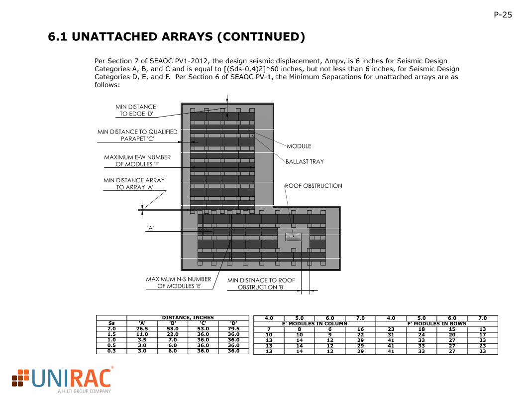
MIN DISTANCE ARRAY TO ARRAY 'A'
MAXIMUM E-W NUMBEROF MODULES 'F'
MAXIMUM N-S NUMBER OF MODULES 'E'
MIN DISTANCE TO QUALIFIEDPARAPET 'C'
MIN DISTANCE TO EDGE 'D'
MIN DISTNACE TO ROOFOBSTRUCTION 'B'
'A'
MODULE
BALLAST TRAY
ROOF OBSTRUCTION
Per Section 7 of SEAOC PV1-2012, the design seismic displacement, ∆mpv, is 6 inches for Seismic Design Categories A, B, and C and is equal to [(Sds-0.4)2]*60 inches, but not less than 6 inches, for Seismic Design Categories D, E, and F. Per Section 6 of SEAOC PV-1, the Minimum Separations for unattached arrays are as follows:
Sheet1
Page 1
DISTANCE, INCHESSs 'A' 'B' 'C' 'D'2.0 26.5 53.0 53.0 79.51.5 11.0 22.0 36.0 36.01.0 3.5 7.0 36.0 36.00.5 3.0 6.0 36.0 36.00.3 3.0 6.0 36.0 36.0
4.0 5.0 6.0 7.0 4.0 5.0 6.0 7.0E' MODULES IN COLUMN F' MODULES IN ROWS
7 8 6 16 23 18 15 1310 10 9 22 31 24 20 1713 14 12 29 41 33 27 2313 14 12 29 41 33 27 2313 14 12 29 41 33 27 23
R
A HILTI GROUP COMPANY
P-26
6.1 UNATTACHED ARRAYS (CONTINUED)
Assumptions: Site class ‘D’, modules are 39”x77”, 55 lbs, Ip and Ie are equal to 1.0, minimum ballast is 32 lbs. for 4 PSF, 52 lbs. for 5 and 6 psf, and 78lbs for 7 PSF
For other module weights, module lengths, and ballast weights:
• For SDS < 0.75
• For SDS > 0.75
Attached Arrays:If a seismic attachment is deemed necessary, this method should suffice as it satisfies SEAOC PV1 2012 and ASCE 7-10, Chapter 13. These documents give the formulas to calculate Fp or the seismic force on the array. That force is compared to the strength of the system to determine the number of seismic penetrations required.
The values ap= 1.0 and Rp=1.5 are recommended by the SEAOC document. Friction can be used to reduce the Fp when all of the following conditions are met:
– Maximum slope= 7 degrees (5.7 is the maximum for the wind tunnel)
– The RM system’s center of mass is less than 36” off the rooftop
– The Rp is equal to 1.5 or less
With these conditions met, the maximum contribution of friction to resisting Fp is (0.9-0.2SDS)(0.7µ)* Weight
The friction coefficient µ must be determined from testing per ASTM G115 for Seismic Design Categories D,E or F. For Seismic Design Categories A,B or C and with a roof surface of mineral-surfaced cap sheet, single ply membrane, or spray foamed membrane (not gravel, wood, or metal) then the friction coefficient can be assumed to be 0.4. (See SEAOC PV1-2012 section 8 for further details.) In the case of the RM array, this can be applied to our calculation of Fp where the Weight of the system (weight of the module, ballast tray, and ballast of the area considered) minus the friction weight (weight of the system divided by a factor of safety of 1.5). (The tray with the seismic penetration should not be moving or using friction.)
To calculate the design seismic load for an array (ASCE 7-10 13.3-1)
R
A HILTI GROUP COMPANY
P-27
6.2 ATTACHED ARRAYS
Where:
– ap= 1.0
– Fa is determined from table 11.4-1, SS is from the maps in ASCE 7-10 figure 22-1, 22-3, 22-5, 22-6.
– SS is from the maps in ASCE 7-10 figure 22-1, 22-3, 22-5, 22-6
– Weight system is the entire system being evaluated.
– Weight friction is the weight of the system divided by factor of safety, 1.5
– Can be taken as 1.0 for typical rooftop PV installations. (RM system is not too high and on top of the roof)
– Ip is the importance factor of the building in question (normally Ip =1.0)
– Rp=1.5From the above, we can calculate the Fp force acting on the array. The Fp force is used to check the ballast tray connections and the seismic attachment. Seismic design of an attached array requires checking these two items.The Seismic force calculated on the array can now be compared with the allowable load on a RapidFoot attachment (1200 lbs) to determine how many attachments are required to resist the forces. Generally, locating the attachments towards the interior of the array and not on the edge is a more effective use of that part.
Attached Array Seismic Design Example:
– Module: 77x39, 55lbs
– Ballast: 26lbs per block
– Wind: 110mph Cat B per ASCE 7-10
– Friction: 0.4
– Site Class: D
– Importance factor: 1
– Array Layout: four modules by four modules (16 total)
– SDS=1.5
– Total Ballast Weight: 4 x 4 array, total blocks needed 75 @ 26lbs
– 25 bays @ 3.5lbsBased on the number of bricks required for each ballast tray, below is the amount of force that would need to be resisted by RapidFoot attachments. )Fp= 3174.2 lbs
This value can now be divided by the capacity of the RapidFeet to determine the quantity of attachments needed. Please round up to next whole number.
R
A HILTI GROUP COMPANY
6.2 ATTACHED ARRAYS (CONTINUED)
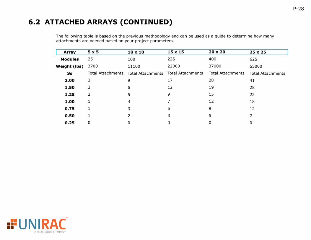
The following table is based on the previous methodology and can be used as a guide to determine how many attachments are needed based on your project parameters.
Array
Modules
Weight (lbs)
Ss
2.00
1.50
1.25
1.00
0.75
0.50
0.25
5 x 5
25
3700
Total Attachments
3
2
2
1
1
1
0
10 x 10
100
11100
Total Attachments
9
6
5
4
3
2
0
15 x 15
225
22000
Total Attachments
17
12
9
7
5
3
0
20 x 20
400
37000
Total Attachments
28
19
15
12
9
5
0
25 x 25
625
55000
Total Attachments
41
28
22
18
12
7
0
P-28
R
A HILTI GROUP COMPANY
P-29
6.2 ATTACHED ARRAYS – ATTACHMENT LOCATION
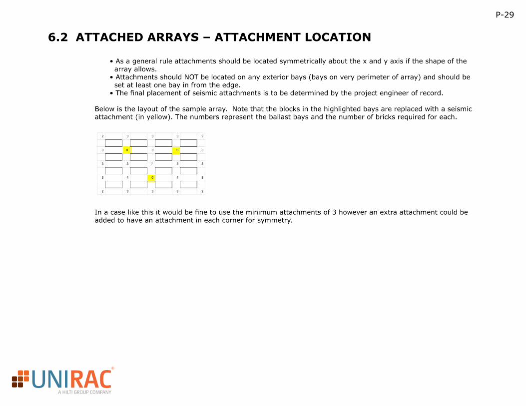
• As a general rule attachments should be located symmetrically about the x and y axis if the shape of the array allows.• Attachments should NOT be located on any exterior bays (bays on very perimeter of array) and should be set at least one bay in from the edge.• The final placement of seismic attachments is to be determined by the project engineer of record.
Below is the layout of the sample array. Note that the blocks in the highlighted bays are replaced with a seismic attachment (in yellow). The numbers represent the ballast bays and the number of bricks required for each.
In a case like this it would be fine to use the minimum attachments of 3 however an extra attachment could be added to have an attachment in each corner for symmetry.
2 3 3 3 2
3 0 3 0 3
3 3 3 3
3 4 0 4 3
2 3 3 3 2
3
R
A HILTI GROUP COMPANY
P-30
7. CALCULATING APPLICABLE WIND LOADS, APPLICABLE STANDARDS
As previously mentioned there are building codes that need to be considered when determining the appropriate wind loads on a PV array. There are 2 main versions of the code that are used for design ASCE 7-05 and the newer ASCE 7-10. Below is a short description of each.
• 7-05: This code incorporates an importance factor into the wind calculations based on the type of building that is being evaluated and typically has lower wind speeds than 7-10 code. Your local building department should tell you if this one is applicable.
• 7-10: This is the newer code that went into effect in 2012 however has only been adopted in a few regions. This code has different wind maps based on the risk category of the building. In general the design wind speeds are high as compared to 7-05 however due to the changes in load combinations the final wind pressures are often lower. We recommend using this code for the RM product in order to obtain lower ballast loads however it’s up to the building department as to whether or not it’s applicable for each respective location.
R
A HILTI GROUP COMPANY
P-31
8. PRESCRIPTIVE STRUCTURAL DESIGN TABLES
8.1 PRESCRIPTIVE STRUCTURAL DESIGN TABLES ASSUMPTIONS/LIMITATIONS
The following design tables are provided to determine how much ballast is needed for each panel based on methodology provided in the proprietary wind tunnel study conducted for Unirac.
Here is a list of assumptions/limitations that your project must fall within in order to be able to use the design tables.
– 60 Cell Module: 68” x 39”, 40 lbs
– 72 Cell Module: 77” x 39”, 55 lbs
– Exposures B or C
– ASCE 7-05 wind speeds (mph): 85, 90, 100, 110 and 120
– ASCE 7-10 wind speeds (mph): 110, 115, 120, 125 and 130
– Building Height (ft): ≤ 60’-0”
– Array must be at least 3’-0” from the edge of the building.
– Parapets: parapet of at least 12” tall requires using parapet design tables.
Regarding module size, as long as your module is less than the specifications listed above you can use these tables. If you’re working with a module larger than this please consult the U-Builder design tool. For the most accurate results we do recommend using our U-Builder design tool.
R
A HILTI GROUP COMPANY
P-32
8.2 PRESCRIPTIVE STRUCTURAL DESIGN TABLES INTERIOR/EXTERIOR MODULES
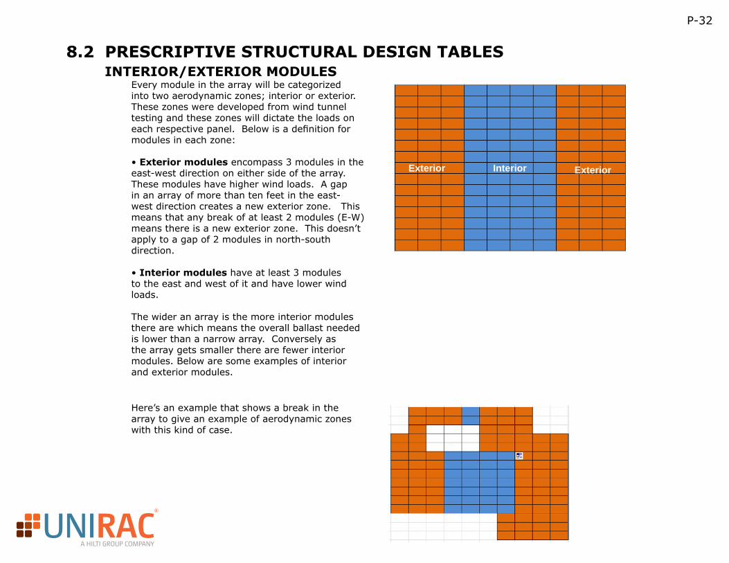
Every module in the array will be categorized into two aerodynamic zones; interior or exterior. These zones were developed from wind tunnel testing and these zones will dictate the loads on each respective panel. Below is a definition for modules in each zone:
• Exterior modules encompass 3 modules in the east-west direction on either side of the array. These modules have higher wind loads. A gap in an array of more than ten feet in the east-west direction creates a new exterior zone. This means that any break of at least 2 modules (E-W) means there is a new exterior zone. This doesn’t apply to a gap of 2 modules in north-south direction.
• Interior modules have at least 3 modules to the east and west of it and have lower wind loads.
The wider an array is the more interior modules there are which means the overall ballast needed is lower than a narrow array. Conversely as the array gets smaller there are fewer interior modules. Below are some examples of interior and exterior modules.
Exterior ExteriorInterior
Here’s an example that shows a break in the array to give an example of aerodynamic zones with this kind of case.
R
A HILTI GROUP COMPANY
P-33
8.3 LOAD SHARING REGIONS
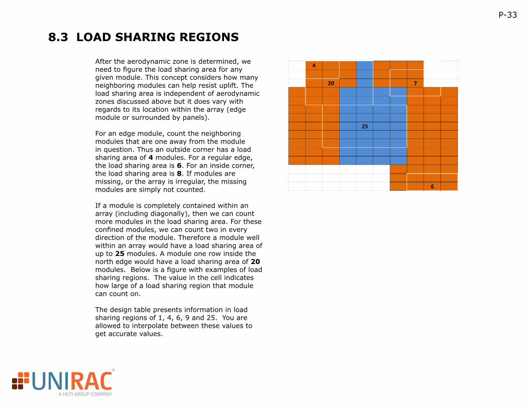
After the aerodynamic zone is determined, we need to figure the load sharing area for any given module. This concept considers how many neighboring modules can help resist uplift. The load sharing area is independent of aerodynamic zones discussed above but it does vary with regards to its location within the array (edge module or surrounded by panels).
For an edge module, count the neighboring modules that are one away from the module in question. Thus an outside corner has a load sharing area of 4 modules. For a regular edge, the load sharing area is 6. For an inside corner, the load sharing area is 8. If modules are missing, or the array is irregular, the missing modules are simply not counted.
If a module is completely contained within an array (including diagonally), then we can count more modules in the load sharing area. For these confined modules, we can count two in every direction of the module. Therefore a module well within an array would have a load sharing area of up to 25 modules. A module one row inside the north edge would have a load sharing area of 20 modules. Below is a figure with examples of load sharing regions. The value in the cell indicates how large of a load sharing region that module can count on.
The design table presents information in load sharing regions of 1, 4, 6, 9 and 25. You are allowed to interpolate between these values to get accurate values.

R
A HILTI GROUP COMPANY
P-34
TABLES A & B
Unirac RM 08/01/13
ExposureWind Speed
Bldg. Height Interior Exterior Interior Exterior Interior Exterior Interior Exterior Interior Exterior15 98 147 59 98 47 86 32 62 13 2530 129 189 81 129 66 114 48 84 24 3960 164 237 106 164 88 146 66 109 37 5515 114 169 71 114 57 101 41 73 19 3230 149 216 95 149 78 132 58 98 31 4860 188 270 123 188 103 168 78 127 46 6615 150 217 96 150 79 133 58 99 31 4830 192 275 126 192 105 171 80 130 47 6860 241 341 160 241 135 216 105 165 65 9015 189 270 123 189 103 168 78 127 46 6630 240 340 160 240 134 215 104 165 64 8960 299 421 201 299 171 268 134 208 86 11615 231 328 154 231 129 207 100 158 61 8530 292 412 197 292 167 262 131 203 83 11360 363 507 247 363 210 326 167 254 109 14515 98 147 59 98 47 86 32 62 13 2530 129 189 81 129 66 114 48 84 24 3960 164 237 106 164 88 146 66 109 37 5515 114 169 71 114 57 101 41 73 19 3230 149 216 95 149 78 132 58 98 31 4860 188 270 123 188 103 168 78 127 46 6615 150 217 96 150 79 133 58 99 31 4830 192 275 126 192 105 171 80 130 47 6860 241 341 160 241 135 216 105 165 65 9015 189 270 123 189 103 168 78 127 46 6630 240 340 160 240 134 215 104 165 64 8960 299 421 201 299 171 268 134 208 86 11615 231 328 154 231 129 207 100 158 61 8530 292 412 197 292 167 262 131 203 83 11360 363 507 247 363 210 326 167 254 109 145
ExposureWind Speed
Bldg. Height Interior Exterior Interior Exterior Interior Exterior Interior Exterior Interior Exterior15 102 158 58 102 44 89 28 61 6 2030 137 205 83 137 66 120 45 86 18 3560 177 259 111 177 90 156 66 115 33 5315 121 183 71 121 56 105 37 74 12 2830 160 236 99 160 80 141 57 103 27 4660 204 297 130 204 107 181 80 135 43 6615 161 237 100 161 80 142 57 103 27 4630 209 302 134 209 110 185 82 138 44 6860 264 378 173 264 144 235 110 178 64 9315 205 297 131 205 108 182 80 135 43 6630 263 376 172 263 144 234 109 178 64 9260 330 468 219 330 185 295 144 226 88 12315 253 363 165 253 138 226 105 171 61 8830 322 457 214 322 180 288 140 221 86 11960 402 566 270 402 229 361 180 279 115 15615 102 158 58 102 44 89 28 61 6 2030 137 205 83 137 66 120 45 86 18 3560 177 259 111 177 90 156 66 115 33 5315 121 183 71 121 56 105 37 74 12 2830 160 236 99 160 80 141 57 103 27 4660 204 297 130 204 107 181 80 135 43 6615 161 237 100 161 80 142 57 103 27 4630 209 302 134 209 110 185 82 138 44 6860 264 378 173 264 144 235 110 178 64 9315 205 297 131 205 108 182 80 135 43 6630 263 376 172 263 144 234 109 178 64 9260 330 468 219 330 185 295 144 226 88 12315 253 363 165 253 138 226 105 171 61 8830 322 457 214 322 180 288 140 221 86 11960 402 566 270 402 229 361 180 279 115 156
90
100
110
120
100
110
120
90
100
72 Cell ‐ No Parapet
100
110
120
85
90
B
C
85
110
120
85
Required Ballast per Module for Load Sharing Region (lbs)ASCE 7‐05 1 module 4 modules 6 modules 9 modules 25 modules
60 Cell ‐ No ParapetASCE 7‐05 25 modules
Required Ballast per Module for Load Sharing Region (lbs)
B
C
1 module 4 modules 6 modules 9 modules
85
90
R
A HILTI GROUP COMPANY
P-35
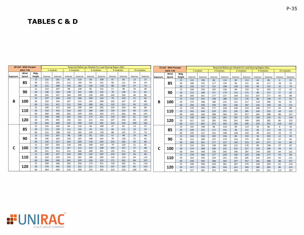
TABLES C & D
Unirac RM 08/01/13
ExposureWind Speed
Bldg. Height Interior Exterior Interior Exterior Interior Exterior Interior Exterior Interior Exterior15 132 181 83 110 69 108 47 83 13 3730 171 230 111 144 93 141 66 111 24 5460 215 288 142 182 120 178 88 142 37 7315 153 207 98 128 82 125 57 98 19 4630 196 263 128 165 108 162 78 128 31 6560 245 327 164 209 139 204 103 164 46 8615 197 264 129 166 109 163 79 129 31 6530 250 333 167 213 142 208 105 167 47 8860 311 412 211 266 180 261 135 211 65 11515 246 327 164 209 140 205 103 164 46 8630 310 410 210 265 180 260 134 210 64 11460 384 506 262 329 226 323 171 262 86 14715 299 396 202 256 173 251 129 202 61 11030 376 495 256 322 221 316 167 256 83 14360 464 609 319 399 276 392 210 319 109 18115 132 181 83 110 69 108 47 83 13 3730 171 230 111 144 93 141 66 111 24 5460 215 288 142 182 120 178 88 142 37 7315 153 207 98 128 82 125 57 98 19 4630 196 263 128 165 108 162 78 128 31 6560 245 327 164 209 139 204 103 164 46 8615 197 264 129 166 109 163 79 129 31 6530 250 333 167 213 142 208 105 167 47 8860 311 412 211 266 180 261 135 211 65 11515 246 327 164 209 140 205 103 164 46 8630 310 410 210 265 180 260 134 210 64 11460 384 506 262 329 226 323 171 262 86 14715 299 396 202 256 173 251 129 202 61 11030 376 495 256 322 221 316 167 256 83 14360 464 609 319 399 276 392 210 319 109 181
ExposureWind Speed
Bldg. Height Interior Exterior Interior Exterior Interior Exterior Interior Exterior Interior Exterior15 141 196 86 116 69 113 44 86 6 3330 184 252 117 154 96 151 66 117 18 5260 235 317 152 198 128 193 90 152 33 7415 164 226 102 136 84 133 56 102 12 4330 213 289 137 179 114 175 80 137 27 6560 269 361 177 227 149 223 107 177 43 8915 214 291 138 180 115 176 80 138 27 6530 274 368 180 232 152 227 110 180 44 9160 344 458 230 292 196 287 144 230 64 12115 270 362 177 228 149 223 108 177 43 8930 342 456 229 291 195 285 144 229 64 12160 426 564 288 364 247 357 185 288 88 15715 330 440 220 281 187 275 138 220 61 11630 417 552 282 356 241 349 180 282 86 15360 517 681 353 443 303 435 229 353 115 19715 141 196 86 116 69 113 44 86 6 3330 184 252 117 154 96 151 66 117 18 5260 235 317 152 198 128 193 90 152 33 7415 164 226 102 136 84 133 56 102 12 4330 213 289 137 179 114 175 80 137 27 6560 269 361 177 227 149 223 107 177 43 8915 214 291 138 180 115 176 80 138 27 6530 274 368 180 232 152 227 110 180 44 9160 344 458 230 292 196 287 144 230 64 12115 270 362 177 228 149 223 108 177 43 8930 342 456 229 291 195 285 144 229 64 12160 426 564 288 364 247 357 185 288 88 15715 330 440 220 281 187 275 138 220 61 11630 417 552 282 356 241 349 180 282 86 15360 517 681 353 443 303 435 229 353 115 197
100
110
120
100
110
120
85
90
85
90
100
110
120
85
90
100
110
120
85
90
72 Cell ‐ With Parapet Required Ballast per Module for Load Sharing Region (lbs)ASCE 7‐05 1 module 4 modules 6 modules 9 modules 25 modules
B
C
B
C
60 Cell ‐ With ParapetASCE 7‐05
Required Ballast per Module for Load Sharing Region (lbs)1 module 4 modules 6 modules 9 modules 25 modules
R
A HILTI GROUP COMPANY
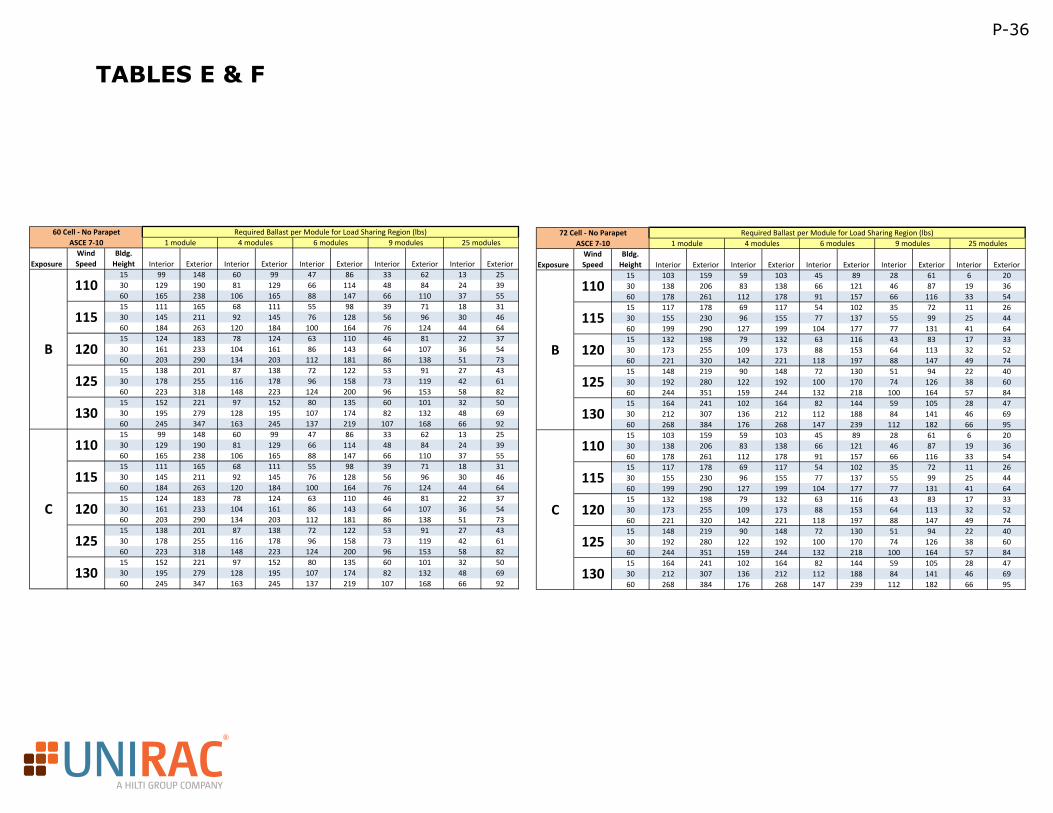
TABLES E & F
Unirac RM 08/01/13
ExposureWind Speed
Bldg. Height Interior Exterior Interior Exterior Interior Exterior Interior Exterior Interior Exterior15 99 148 60 99 47 86 33 62 13 2530 129 190 81 129 66 114 48 84 24 3960 165 238 106 165 88 147 66 110 37 5515 111 165 68 111 55 98 39 71 18 3130 145 211 92 145 76 128 56 96 30 4660 184 263 120 184 100 164 76 124 44 6415 124 183 78 124 63 110 46 81 22 3730 161 233 104 161 86 143 64 107 36 5460 203 290 134 203 112 181 86 138 51 7315 138 201 87 138 72 122 53 91 27 4330 178 255 116 178 96 158 73 119 42 6160 223 318 148 223 124 200 96 153 58 8215 152 221 97 152 80 135 60 101 32 5030 195 279 128 195 107 174 82 132 48 6960 245 347 163 245 137 219 107 168 66 9215 99 148 60 99 47 86 33 62 13 2530 129 190 81 129 66 114 48 84 24 3960 165 238 106 165 88 147 66 110 37 5515 111 165 68 111 55 98 39 71 18 3130 145 211 92 145 76 128 56 96 30 4660 184 263 120 184 100 164 76 124 44 6415 124 183 78 124 63 110 46 81 22 3730 161 233 104 161 86 143 64 107 36 5460 203 290 134 203 112 181 86 138 51 7315 138 201 87 138 72 122 53 91 27 4330 178 255 116 178 96 158 73 119 42 6160 223 318 148 223 124 200 96 153 58 8215 152 221 97 152 80 135 60 101 32 5030 195 279 128 195 107 174 82 132 48 6960 245 347 163 245 137 219 107 168 66 92
ExposureWind Speed
Bldg. Height Interior Exterior Interior Exterior Interior Exterior Interior Exterior Interior Exterior15 103 159 59 103 45 89 28 61 6 2030 138 206 83 138 66 121 46 87 19 3660 178 261 112 178 91 157 66 116 33 5415 117 178 69 117 54 102 35 72 11 2630 155 230 96 155 77 137 55 99 25 4460 199 290 127 199 104 177 77 131 41 6415 132 198 79 132 63 116 43 83 17 3330 173 255 109 173 88 153 64 113 32 5260 221 320 142 221 118 197 88 147 49 7415 148 219 90 148 72 130 51 94 22 4030 192 280 122 192 100 170 74 126 38 6060 244 351 159 244 132 218 100 164 57 8415 164 241 102 164 82 144 59 105 28 4730 212 307 136 212 112 188 84 141 46 6960 268 384 176 268 147 239 112 182 66 9515 103 159 59 103 45 89 28 61 6 2030 138 206 83 138 66 121 46 87 19 3660 178 261 112 178 91 157 66 116 33 5415 117 178 69 117 54 102 35 72 11 2630 155 230 96 155 77 137 55 99 25 4460 199 290 127 199 104 177 77 131 41 6415 132 198 79 132 63 116 43 83 17 3330 173 255 109 173 88 153 64 113 32 5260 221 320 142 221 118 197 88 147 49 7415 148 219 90 148 72 130 51 94 22 4030 192 280 122 192 100 170 74 126 38 6060 244 351 159 244 132 218 100 164 57 8415 164 241 102 164 82 144 59 105 28 4730 212 307 136 212 112 188 84 141 46 6960 268 384 176 268 147 239 112 182 66 95
130
125
130
110
115
120
125
110
115
120
125
130
C
110
115
120B
ASCE 7‐10 1 module 4 modules 6 modules 9 modules 25 modules
B
C
72 Cell ‐ No Parapet Required Ballast per Module for Load Sharing Region (lbs)
110
115
120
125
130
60 Cell ‐ No Parapet Required Ballast per Module for Load Sharing Region (lbs)ASCE 7‐10 1 module 4 modules 6 modules 9 modules 25 modules
P-36
R
A HILTI GROUP COMPANY
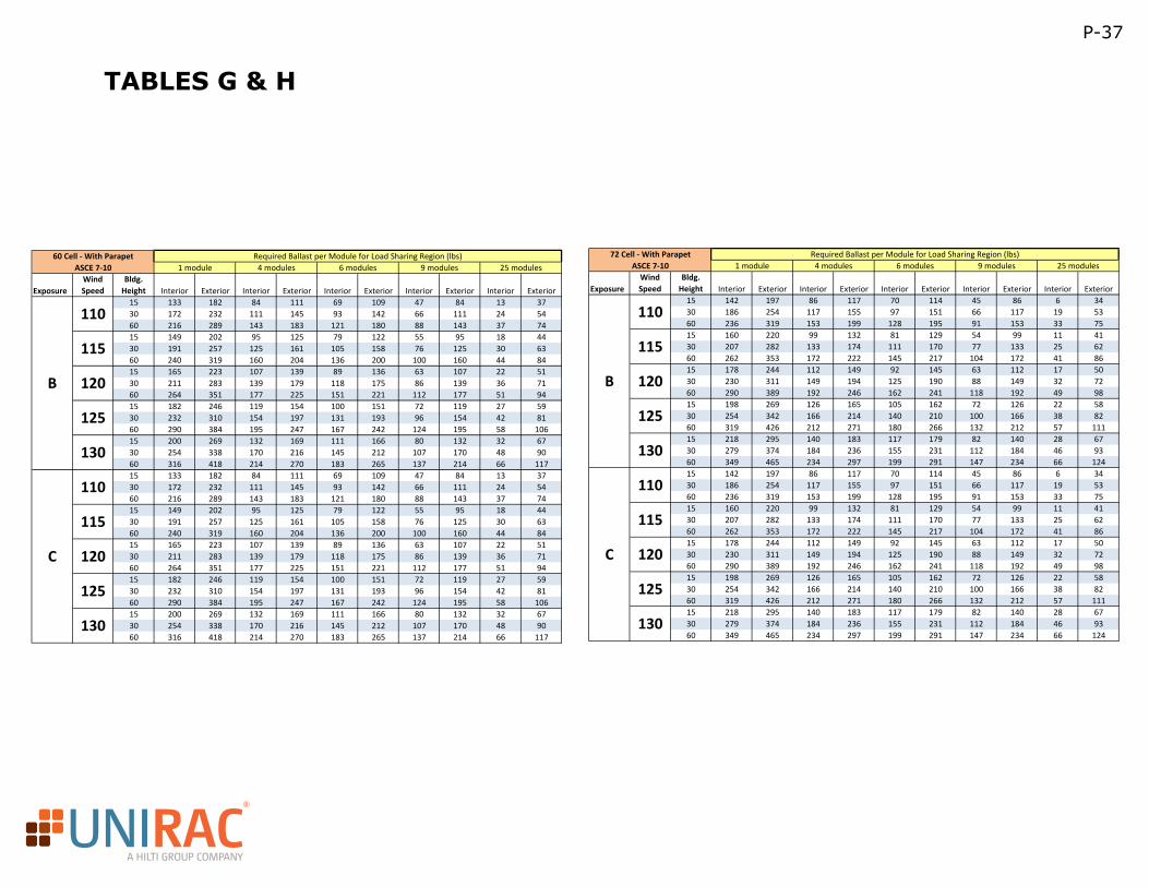
TABLES G & H
Unirac RM 08/01/13
ExposureWind Speed
Bldg. Height Interior Exterior Interior Exterior Interior Exterior Interior Exterior Interior Exterior15 133 182 84 111 69 109 47 84 13 3730 172 232 111 145 93 142 66 111 24 5460 216 289 143 183 121 180 88 143 37 7415 149 202 95 125 79 122 55 95 18 4430 191 257 125 161 105 158 76 125 30 6360 240 319 160 204 136 200 100 160 44 8415 165 223 107 139 89 136 63 107 22 5130 211 283 139 179 118 175 86 139 36 7160 264 351 177 225 151 221 112 177 51 9415 182 246 119 154 100 151 72 119 27 5930 232 310 154 197 131 193 96 154 42 8160 290 384 195 247 167 242 124 195 58 10615 200 269 132 169 111 166 80 132 32 6730 254 338 170 216 145 212 107 170 48 9060 316 418 214 270 183 265 137 214 66 11715 133 182 84 111 69 109 47 84 13 3730 172 232 111 145 93 142 66 111 24 5460 216 289 143 183 121 180 88 143 37 7415 149 202 95 125 79 122 55 95 18 4430 191 257 125 161 105 158 76 125 30 6360 240 319 160 204 136 200 100 160 44 8415 165 223 107 139 89 136 63 107 22 5130 211 283 139 179 118 175 86 139 36 7160 264 351 177 225 151 221 112 177 51 9415 182 246 119 154 100 151 72 119 27 5930 232 310 154 197 131 193 96 154 42 8160 290 384 195 247 167 242 124 195 58 10615 200 269 132 169 111 166 80 132 32 6730 254 338 170 216 145 212 107 170 48 9060 316 418 214 270 183 265 137 214 66 117
ExposureWind Speed
Bldg. Height Interior Exterior Interior Exterior Interior Exterior Interior Exterior Interior Exterior15 142 197 86 117 70 114 45 86 6 3430 186 254 117 155 97 151 66 117 19 5360 236 319 153 199 128 195 91 153 33 7515 160 220 99 132 81 129 54 99 11 4130 207 282 133 174 111 170 77 133 25 6260 262 353 172 222 145 217 104 172 41 8615 178 244 112 149 92 145 63 112 17 5030 230 311 149 194 125 190 88 149 32 7260 290 389 192 246 162 241 118 192 49 9815 198 269 126 165 105 162 72 126 22 5830 254 342 166 214 140 210 100 166 38 8260 319 426 212 271 180 266 132 212 57 11115 218 295 140 183 117 179 82 140 28 6730 279 374 184 236 155 231 112 184 46 9360 349 465 234 297 199 291 147 234 66 12415 142 197 86 117 70 114 45 86 6 3430 186 254 117 155 97 151 66 117 19 5360 236 319 153 199 128 195 91 153 33 7515 160 220 99 132 81 129 54 99 11 4130 207 282 133 174 111 170 77 133 25 6260 262 353 172 222 145 217 104 172 41 8615 178 244 112 149 92 145 63 112 17 5030 230 311 149 194 125 190 88 149 32 7260 290 389 192 246 162 241 118 192 49 9815 198 269 126 165 105 162 72 126 22 5830 254 342 166 214 140 210 100 166 38 8260 319 426 212 271 180 266 132 212 57 11115 218 295 140 183 117 179 82 140 28 6730 279 374 184 236 155 231 112 184 46 9360 349 465 234 297 199 291 147 234 66 124
130
110
115
120
125
130
110
115
120
125
130
130
110
115
120
125
C
B
Required Ballast per Module for Load Sharing Region (lbs)ASCE 7‐10 1 module 4 modules 6 modules 9 modules 25 modules
B
C
72 Cell ‐ With Parapet
110
115
120
125
25 modules60 Cell ‐ With Parapet Required Ballast per Module for Load Sharing Region (lbs)
ASCE 7‐10 1 module 4 modules 6 modules 9 modules
P-37
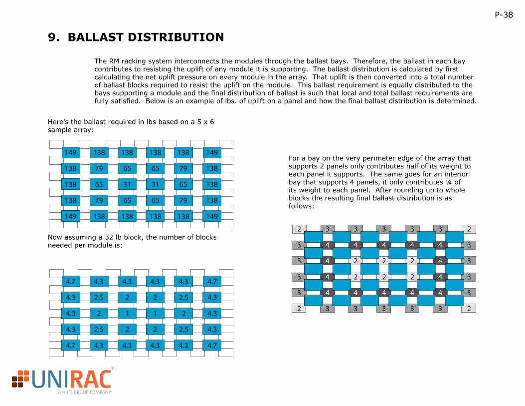
R
A HILTI GROUP COMPANY
P-38
9. BALLAST DISTRIBUTION
The RM racking system interconnects the modules through the ballast bays. Therefore, the ballast in each bay contributes to resisting the uplift of any module it is supporting. The ballast distribution is calculated by first calculating the net uplift pressure on every module in the array. That uplift is then converted into a total number of ballast blocks required to resist the uplift on the module. This ballast requirement is equally distributed to the bays supporting a module and the final distribution of ballast is such that local and total ballast requirements are fully satisfied. Below is an example of lbs. of uplift on a panel and how the final ballast distribution is determined.
Here’s the ballast required in lbs based on a 5 x 6 sample array:
Now assuming a 32 lb block, the number of blocks needed per module is:
For a bay on the very perimeter edge of the array that supports 2 panels only contributes half of its weight to each panel it supports. The same goes for an interior bay that supports 4 panels, it only contributes ¼ of its weight to each panel. After rounding up to whole blocks the resulting final ballast distribution is as follows:
149 138 138
138138
79 65
65
31
138
138
65
65
31
79
65
138
138
79
79
65
149
138
138
138
149
149
138
138
138
4.7 4.3 4.3
4.34.3
2.5 2
2
1
4.3
4.3
2
2
1
2.5
2
4.3
4.3
2.5
2.5
2
4.7
4.3
4.3
4.3
4.7
4.7
4.3
4.3
4.3
2
2
3
3
3
3
2
2
3
3
3
3
3
3
4
4
4
4
3
3
4
4
4
4
3
3
4
2
2
4
3
3
4
2
2
4
3
3
4
2
2
4
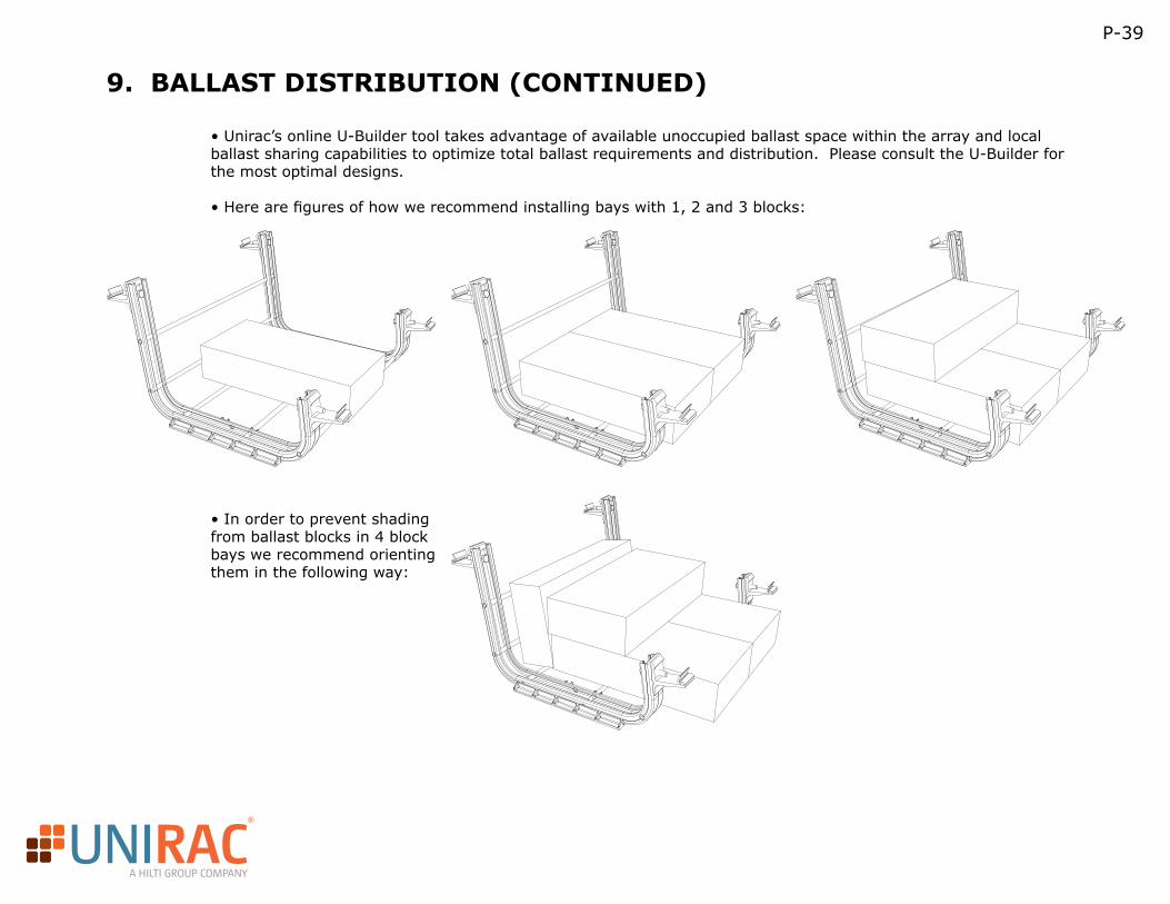
R
A HILTI GROUP COMPANY
P-39
9. BALLAST DISTRIBUTION (CONTINUED)
• Unirac’s online U-Builder tool takes advantage of available unoccupied ballast space within the array and local ballast sharing capabilities to optimize total ballast requirements and distribution. Please consult the U-Builder for the most optimal designs.
• Here are figures of how we recommend installing bays with 1, 2 and 3 blocks:
• In order to prevent shading from ballast blocks in 4 block bays we recommend orienting them in the following way:
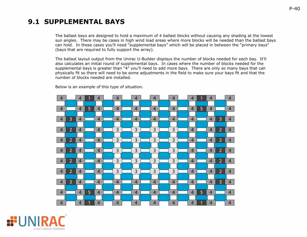
R
A HILTI GROUP COMPANY
P-40
9.1 SUPPLEMENTAL BAYS
The ballast bays are designed to hold a maximum of 4 ballast blocks without causing any shading at the lowest sun angles. There may be cases in high wind load areas where more blocks will be needed than the ballast bays can hold. In these cases you’ll need “supplemental bays” which will be placed in between the “primary bays” (bays that are required to fully support the array).
The ballast layout output from the Unirac U-Builder displays the number of blocks needed for each bay. It’ll also calculates an initial round of supplemental bays. In cases where the number of blocks needed for the supplemental bays is greater than “4” you’ll need to add more bays. There are only so many bays that can physically fit so there will need to be some adjustments in the field to make sure your bays fit and that the number of blocks needed are installed.
Below is an example of this type of situation.
4
4
4
4
4
4
4
3
4
4
3
3
4
4
4
4
4
4
4
3
4
4
3
3
4
4
4
4
4
4
4
3
4
4
3
3
4
3
4
4
3
3
4
4
4
4
4
4
4
4
4
4
4
4
4
4
4
4
4
4
4
4
4
4
4
4
3
3
4
4
4
4
4
4
4
4
3
3
4
4
4
4
4
4
4
4
3
3
4
4
4
3
3
4
4
4
4
4
4
4
4
4
4
4
4
2
3
2
2
1
5
2
3
2
2
1
5
2
2
3
1
5
2
2
3
1
5
4
4
4
4
4
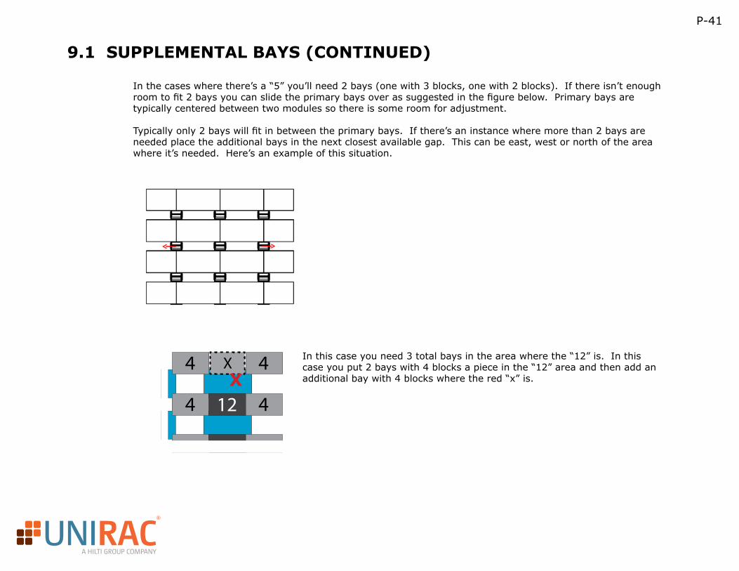
R
A HILTI GROUP COMPANY
P-41
9.1 SUPPLEMENTAL BAYS (CONTINUED)
In the cases where there’s a “5” you’ll need 2 bays (one with 3 blocks, one with 2 blocks). If there isn’t enough room to fit 2 bays you can slide the primary bays over as suggested in the figure below. Primary bays are typically centered between two modules so there is some room for adjustment.
Typically only 2 bays will fit in between the primary bays. If there’s an instance where more than 2 bays are needed place the additional bays in the next closest available gap. This can be east, west or north of the area where it’s needed. Here’s an example of this situation.
In this case you need 3 total bays in the area where the “12” is. In this case you put 2 bays with 4 blocks a piece in the “12” area and then add an additional bay with 4 blocks where the red “x” is.
4
4
4
412
XX
R
A HILTI GROUP COMPANY
P-42
9.2 MAX POINT LOAD: HOW TO CALCULATE
To find the worst case for point loading of our ballast trays, we need to find the ballast tray with the most ballast and carrying 4* ¼ of the modules weight. In other words, if a module has more than four ballast trays attached, the point load is spread out more. If a ballast tray has fewer than four modules attached to it, then the load is also spread out.
Footprint of the RM tray: 2x 1.6”x12” (measured from testing on a soft surface) Weight of ballast tray: 3.5lbs
Sample Inputs:
Module size : 77”x39”
Module weight: 55lbs
Ground Snow load (ASCE 7 figure 7-1): 20psf
Note that the ground snow load can be reduced since this is a roof application.
Max weight of ballast: 128lbs
As you can see this calculation includes the snow load which may not always be required. For more extreme events, Unirac does have an accessory that can help. The roof pad snaps into the bottom of the ballast tray to provide protection from abrasion and improve point loading. Since the pad is made of a TPE, it is flexible and the effective area is not quite the physical area. From our testing, the effective footprint of the RM tray with the roof pads is 51.4 in2. Using this value the applied load to the roof would be the following:
R
A HILTI GROUP COMPANY
P-43
10. U-BUILDER
Unirac’s new U-Builder online tool makes designing, customizing and sharing information extremely simple. The U-Builder provides bills of materials for purchasing, detailed part lists for shipping and receiving, engineering reports for permitting and inspection and row-by-row layout design for the installers. A trove of project specific information is available for download attached to each project.
Automated Design for Unirac’s Roof MountOur new flat roof product will launch with its own U-Builder tool. This tool will allow arrays of up to 50 rows and 50 columns along with the ability to combine several arrays into a single bill of materials. We’ve engineered this product with the most comprehensive wind tunnel analysis in the industry. The U-Builder will generate a ballast map describing exactly how much ballast is required and where to place it. The map also includes a row-by-row report with the number of modules, racking components and ballast required, making the layout and install as simple as possible.
Simple, Comprehensive and FlexibleUnirac’s U-Builder was designed from the start to accommodate varied, new and changing engineering requirements including various building codes. The RM U-Builder tool will launch with IBC 2009 and IBC 2012 codes. The available codes can be expanded to include European and Japanese codes as well.
10.1 INTRODUCTION
R
A HILTI GROUP COMPANY
P-44
10.2 U-BUILDER USER GUIDE
Below is a description of each step within the U-Builder:
PV Module: First step is to select the appropriate PV module for your project. This is critical as it will determine overall array dimension and will also take into account the weight of the panel in the calculations.
Layout: Next input your layout into the tool by dragging the slider bars on the right side of the grid and below the grid to get the overall size. You can then click on individual modules to input any breaks in the array that you may have due to roof obstruction.
Location inputs: Next fill in the appropriate project inputs which include wind speed, snow load, exposure, seismic building height, block weight parapet height and building code. All of these inputs should be verified by your local building department. Click the orange “CONTINUE” button to go to the next page.
Select Accessories: Click the drop down box on the header to be able to select Seismic Attachments, Roof Pads and WEEB Lugs if you choose to.
Complete Parts List: At this step you can adjust the part quantities if you choose to. The number parts automatically generated are minimum quantities to build the array. Click the orange “CONTINUE” button to go to the next page.
Project Info: Within this box you can click the “EDIT” link next to each of the respective titles to input the project information.
Design Results: In this section there are direct links to the “Bill of Materials”, “Engineering Report” and the “Installation and Design Plan” where you can either open each respective one or you can print them directly from the printer icon links.
Product Documents: In this section are links to all product documentation including guides, manuals and certification letters.
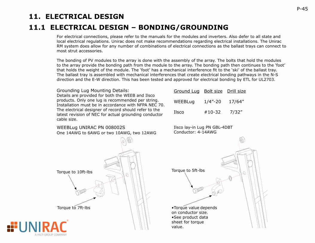
R
A HILTI GROUP COMPANY
Grounding Lug Mounting Details:Details are provided for both the WEEB and Ilsco products. Only one lug is recommended per string. Installation must be in accordance with NFPA NEC 70. The electrical designer of record should refer to the latest revision of NEC for actual grounding conductor cable size.
P-45
11. ELECTRICAL DESIGN
11.1 ELECTRICAL DESIGN – BONDING/GROUNDINGFor electrical connections, please refer to the manuals for the modules and inverters. Also defer to all state and local electrical regulations. Unirac does not make recommendations regarding electrical installations. The Unirac RM system does allow for any number of combinations of electrical connections as the ballast trays can connect to most strut accessories.
The bonding of PV modules to the array is done with the assembly of the array. The bolts that hold the modules to the array provide the bonding path from the module to the array. The bonding path then continues to the ‘foot’ that holds the weight of the module. The ‘foot’ has a mechanical interference fit to the ‘ski’ of the ballast tray. The ballast tray is assembled with mechanical interferences that create electrical bonding pathways in the N-S direction and the E-W direction. This has been tested and approved for electrical bonding by ETL for UL2703.
Ground Lug Bolt size Drill size
WEEBLug 1/4”-20 17/64”
Ilsco #10-32 7/32”
WEEBLug UNIRAC PN 008002SOne 14AWG to 6AWG or two 10AWG, two 12AWG
Ilsco lay-in Lug PN GBL-4DBTConductor: 4-14AWG
Torque to 10ft-lbs
Torque to 7ft-lbs •Torque value depends on conductor size. •See product data sheet for torque value.
Torque to 5ft-lbs
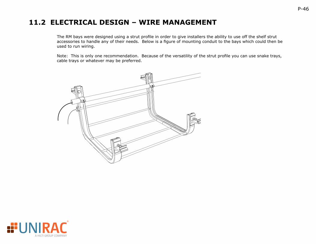
R
A HILTI GROUP COMPANY
P-46
11.2 ELECTRICAL DESIGN – WIRE MANAGEMENT
The RM bays were designed using a strut profile in order to give installers the ability to use off the shelf strut accessories to handle any of their needs. Below is a figure of mounting conduit to the bays which could then be used to run wiring.
Note: This is only one recommendation. Because of the versatility of the strut profile you can use snake trays, cable trays or whatever may be preferred.
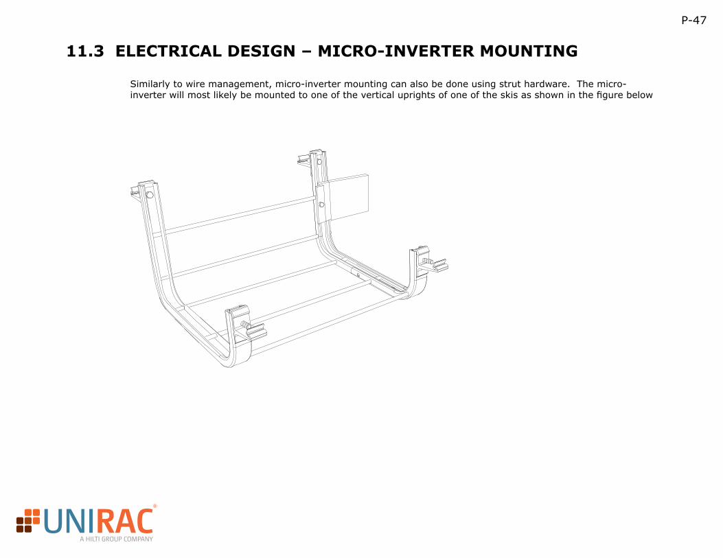
R
A HILTI GROUP COMPANY
P-47
11.3 ELECTRICAL DESIGN – MICRO-INVERTER MOUNTING
Similarly to wire management, micro-inverter mounting can also be done using strut hardware. The micro-inverter will most likely be mounted to one of the vertical uprights of one of the skis as shown in the figure below
R
A HILTI GROUP COMPANY
P-48
11.4 ELECTRICAL DESIGN – DESIGN ENGINEER OF RECORD
With all solar installations we recommend having a design professional review the project just to ensure that all appropriate inputs were used and that the array is installed in a code compliant manner. This includes making sure the array is structurally and electrically sound not to mention with any ballasted installation it is important to have the structure professionally analyzed to make sure it is adequate to support the installation.Unirac does have 3rd party PE contacts that we’re happy to recommend to be your reviewing engineer.
11.5 ELECTRICAL DESIGN – AHJ HAS FINAL SAY
For most locations, there may be a number of inspections required as you near the end of the installation. Some examples of different inspections that may be required include: Electrical Inspection: In order to complete many interconnection agreements, a signed and approved local or state electrical inspection may be required. The electrical inspector verifies compliance with the applicable electrical codes.
Utility Inspection: Some utilities want to inspect, or at least reserve the right to inspect the PV installation. This inspection may be to verify code compliance, that proper utility disconnects are present or to check information provided in the interconnection application.
Building Inspection: Some jurisdictions may require the construction to be approved by a building inspector.
Other entities: In locations where non-utility rebates are available, the entity providing the incentive may require a separate inspection.
The PV installation industry is still considered a young one, and the popularity of PV is growing rapidly, which can lead to a fair amount of confusion even among inspection authorities. While everyone has safety at the core of their motivations, it will take a while for concrete, consistent, and accurate information to find its way to all of the stakeholders. Some inspection officials may require items that are not always anticipated by manufacturers, especially in terms of the support structure. Make sure to have an overabundance of documentation and information at your fingertips to satisfy even the most demanding inspector, or, better yet, use materials and products endorsed by agencies already familiar to them.
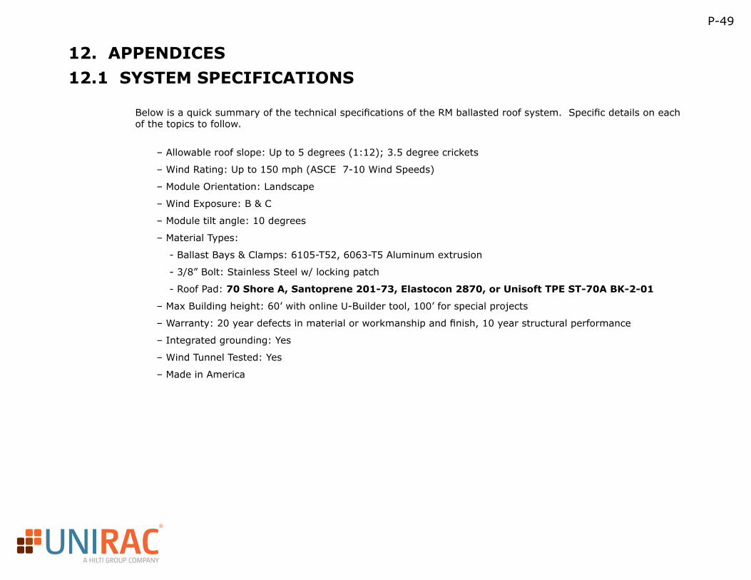
R
A HILTI GROUP COMPANY
P-49
12. APPENDICES
Below is a quick summary of the technical specifications of the RM ballasted roof system. Specific details on each of the topics to follow.
– Allowable roof slope: Up to 5 degrees (1:12); 3.5 degree crickets
– Wind Rating: Up to 150 mph (ASCE 7-10 Wind Speeds)
– Module Orientation: Landscape
– Wind Exposure: B & C
– Module tilt angle: 10 degrees
– Material Types:
- Ballast Bays & Clamps: 6105-T52, 6063-T5 Aluminum extrusion
- 3/8” Bolt: Stainless Steel w/ locking patch
- Roof Pad: 70 Shore A, Santoprene 201-73, Elastocon 2870, or Unisoft TPE ST-70A BK-2-01
– Max Building height: 60’ with online U-Builder tool, 100’ for special projects
– Warranty: 20 year defects in material or workmanship and finish, 10 year structural performance
– Integrated grounding: Yes
– Wind Tunnel Tested: Yes
– Made in America
12.1 SYSTEM SPECIFICATIONS
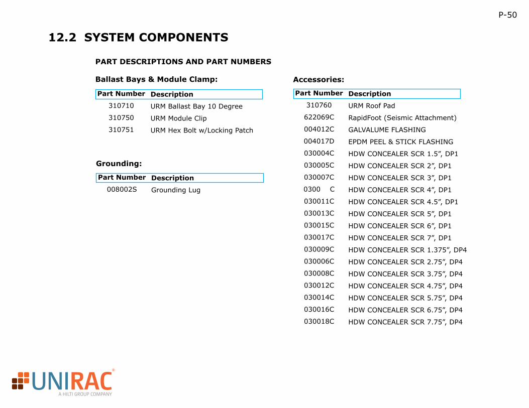
R
A HILTI GROUP COMPANY
P-50
12.2 SYSTEM COMPONENTS
Part Number
310710
310750
310751
Part Number
008002S
Part Number
310760
622069C
004012C
004017D
030004C
030005C
030007C
0300 C
030011C
030013C
030015C
030017C
030009C
030006C
030008C
030012C
030014C
030016C
030018C
Description
URM Ballast Bay 10 Degree
URM Module Clip
URM Hex Bolt w/Locking Patch
Description
Grounding Lug
Description
URM Roof Pad
RapidFoot (Seismic Attachment)
GALVALUME FLASHING
EPDM PEEL & STICK FLASHING
HDW CONCEALER SCR 1.5”, DP1
HDW CONCEALER SCR 2”, DP1
HDW CONCEALER SCR 3”, DP1
HDW CONCEALER SCR 4”, DP1
HDW CONCEALER SCR 4.5”, DP1
HDW CONCEALER SCR 5”, DP1
HDW CONCEALER SCR 6”, DP1
HDW CONCEALER SCR 7”, DP1
HDW CONCEALER SCR 1.375”, DP4
HDW CONCEALER SCR 2.75”, DP4
HDW CONCEALER SCR 3.75”, DP4
HDW CONCEALER SCR 4.75”, DP4
HDW CONCEALER SCR 5.75”, DP4
HDW CONCEALER SCR 6.75”, DP4
HDW CONCEALER SCR 7.75”, DP4
PART DESCRIPTIONS AND PART NUMBERS
Ballast Bays & Module Clamp: Accessories:
Grounding:
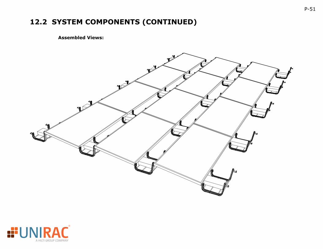
R
A HILTI GROUP COMPANY
P-51
12.2 SYSTEM COMPONENTS (CONTINUED)
Assembled Views:
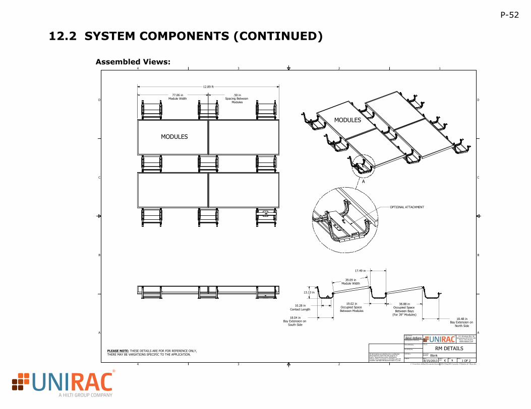
R
A HILTI GROUP COMPANY
P-52
12.2 SYSTEM COMPONENTS (CONTINUED)
A
1
1
2
2
3
3
4
4
A A
B B
C C
D D
DRAWING NUMBER:
REV:
1 OF 2 SHEET:SHEET
SIZE:
1411 Broadway Blvd. NEAlbuquerque NM 87102 USA
Phone: 505.242.6411WWW.UNIRAC.COM
TITLE:
C:\Users\dave dellara\Documents\Inventor\RM 10deg\RM Assemby 4 Modules & 9 Bays.idw
1CFINISH:
MATERIAL:All information provided herein is confidential and proprietary and is the Sole property of Unirac. Reproduction and/or distribution without written permission is forbidden and will constitite copyright infringement under U.S. law
DRAFTSMAN:
ENGINEERING APPROVAL:dave dellara
MFG APPROVAL:
8/15/2013DATE:
PM APPROVAL:
Blank
MODULES
MODULES
RM DETAILS
77.06 inModule Width
.50 inSpacing Between
Modules
12.89 ft
13.13 in
10.28 inContact Length
39.09 inModule Width
19.02 inOccupied Space Between Modules
38.88 inOccupied Space Between Bays
(For 39" Modules)18.48 in
Bay Extension on North Side
18.04 inBay Extension on
South Side
17.49 in
OPTIONAL ATTACHMENT
PLEASE NOTE: THESE DETAILS ARE FOR FOR REFERENCE ONLY,THERE MAY BE VARIATIONS SPECIFIC TO THE APPLICATION.
Assembled Views:
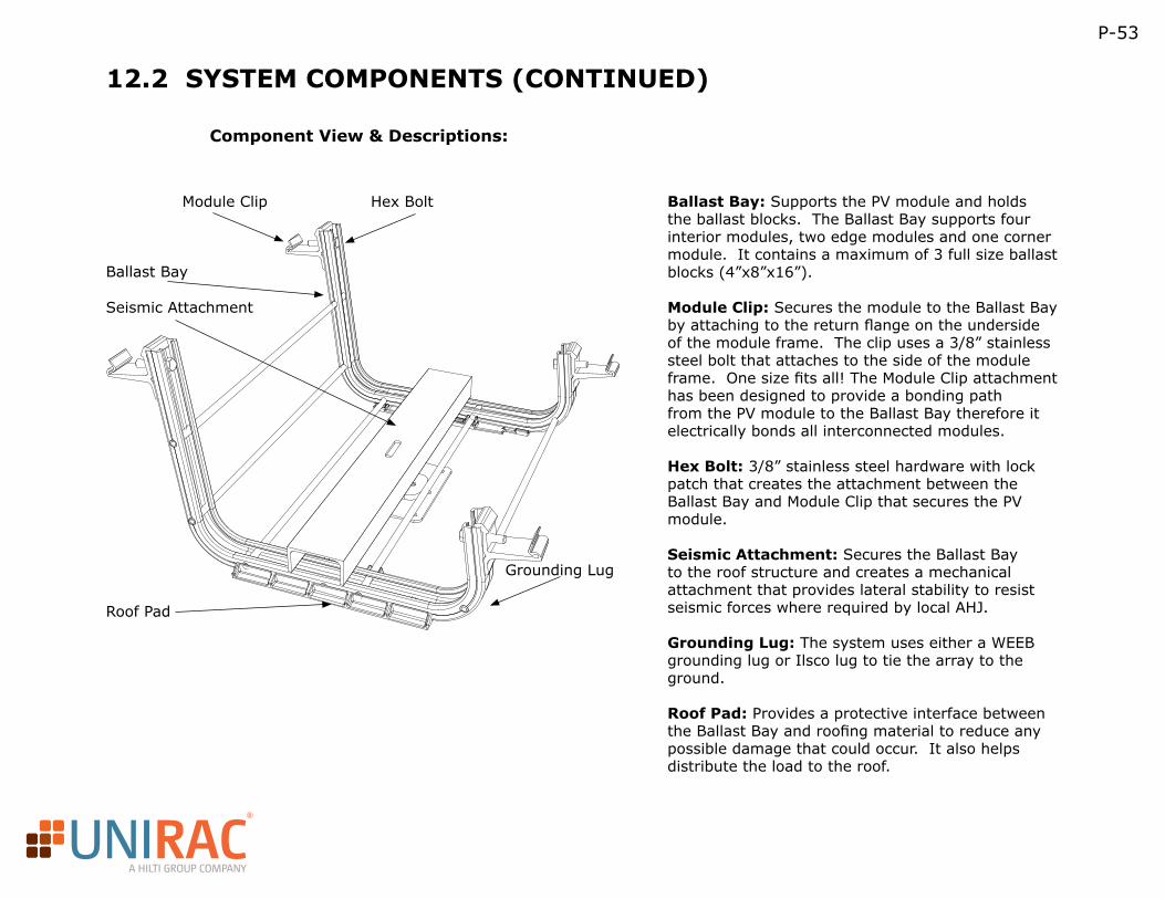
R
A HILTI GROUP COMPANY
P-53
12.2 SYSTEM COMPONENTS (CONTINUED)
Component View & Descriptions:
Module Clip
Ballast Bay
Roof Pad
Hex Bolt
Seismic Attachment
Grounding Lug
Ballast Bay: Supports the PV module and holds the ballast blocks. The Ballast Bay supports four interior modules, two edge modules and one corner module. It contains a maximum of 3 full size ballast blocks (4”x8”x16”).
Module Clip: Secures the module to the Ballast Bay by attaching to the return flange on the underside of the module frame. The clip uses a 3/8” stainless steel bolt that attaches to the side of the module frame. One size fits all! The Module Clip attachment has been designed to provide a bonding path from the PV module to the Ballast Bay therefore it electrically bonds all interconnected modules.
Hex Bolt: 3/8” stainless steel hardware with lock patch that creates the attachment between the Ballast Bay and Module Clip that secures the PV module.
Seismic Attachment: Secures the Ballast Bay to the roof structure and creates a mechanical attachment that provides lateral stability to resist seismic forces where required by local AHJ.
Grounding Lug: The system uses either a WEEB grounding lug or Ilsco lug to tie the array to the ground.
Roof Pad: Provides a protective interface between the Ballast Bay and roofing material to reduce any possible damage that could occur. It also helps distribute the load to the roof.
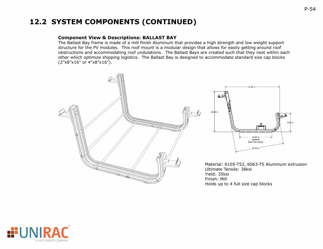
R
A HILTI GROUP COMPANY
P-54
12.2 SYSTEM COMPONENTS (CONTINUED)
Component View & Descriptions: BALLAST BAYThe Ballast Bay frame is made of a mill finish Aluminum that provides a high strength and low weight support structure for the PV modules. This roof mount is a modular design that allows for easily getting around roof obstructions and accommodating roof undulations. The Ballast Bays are created such that they nest within each other which optimize shipping logistics. The Ballast Bay is designed to accommodate standard size cap blocks (2”x8”x16” or 4”x8”x16”).
Material: 6105-T52, 6063-T5 Aluminum extrusionUltimate Tensile: 38ksiYield: 35ksiFinish: MillHolds up to 4 full size cap blocks
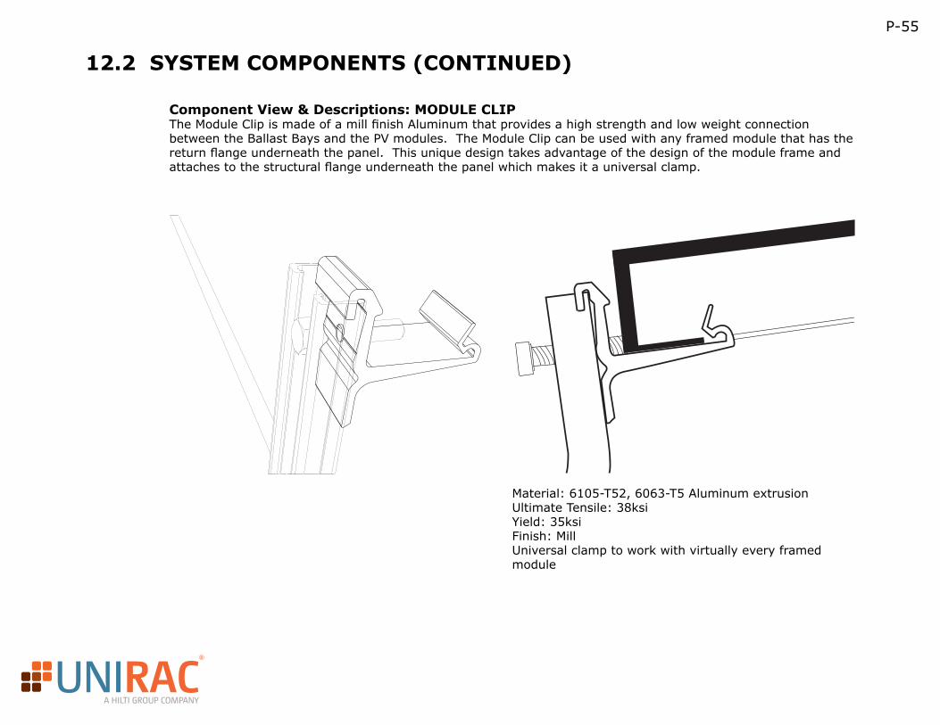
R
A HILTI GROUP COMPANY
P-55
12.2 SYSTEM COMPONENTS (CONTINUED)
Component View & Descriptions: MODULE CLIPThe Module Clip is made of a mill finish Aluminum that provides a high strength and low weight connection between the Ballast Bays and the PV modules. The Module Clip can be used with any framed module that has the return flange underneath the panel. This unique design takes advantage of the design of the module frame and attaches to the structural flange underneath the panel which makes it a universal clamp.
Material: 6105-T52, 6063-T5 Aluminum extrusionUltimate Tensile: 38ksiYield: 35ksiFinish: MillUniversal clamp to work with virtually every framed module
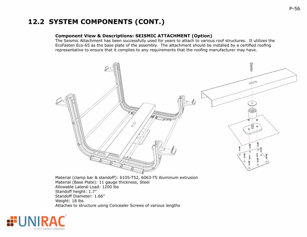
R
A HILTI GROUP COMPANY
P-56
12.2 SYSTEM COMPONENTS (CONT.)
Component View & Descriptions: SEISMIC ATTACHMENT (Option)The Seismic Attachment has been successfully used for years to attach to various roof structures. It utilizes the EcoFasten Eco-65 as the base plate of the assembly. The attachment should be installed by a certified roofing representative to ensure that it complies to any requirements that the roofing manufacturer may have.
Material (clamp bar & standoff): 6105-T52, 6063-T5 Aluminum extrusionMaterial (Base Plate): 11 gauge thickness, SteelAllowable Lateral Load: 1200 lbsStandoff height: 1.7”Standoff Diameter: 1.66”Weight: 18 lbsAttaches to structure using Concealer Screws of various lengths
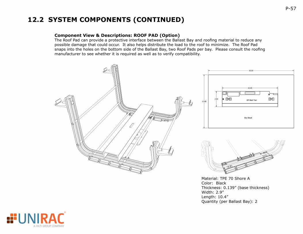
R
A HILTI GROUP COMPANY
P-57
12.2 SYSTEM COMPONENTS (CONTINUED)
Component View & Descriptions: ROOF PAD (Option)The Roof Pad can provide a protective interface between the Ballast Bay and roofing material to reduce any possible damage that could occur. It also helps distribute the load to the roof to minimize. The Roof Pad snaps into the holes on the bottom side of the Ballast Bay, two Roof Pads per bay. Please consult the roofing manufacturer to see whether it is required as well as to verify compatibility.
Material: TPE 70 Shore AColor: BlackThickness: 0.139” (base thickness)Width: 2.9”Length: 10.4”Quantity (per Ballast Bay): 2
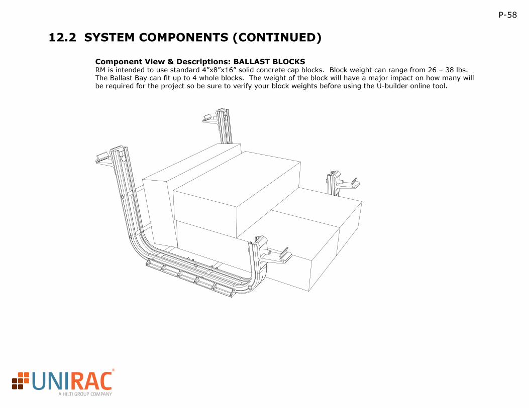
R
A HILTI GROUP COMPANY
P-58
12.2 SYSTEM COMPONENTS (CONTINUED)
Component View & Descriptions: BALLAST BLOCKSRM is intended to use standard 4”x8”x16” solid concrete cap blocks. Block weight can range from 26 – 38 lbs. The Ballast Bay can fit up to 4 whole blocks. The weight of the block will have a major impact on how many will be required for the project so be sure to verify your block weights before using the U-builder online tool.


![Java Script: Arrays (Chapter 11 in [2]). 2 Outline Introduction Introduction Arrays Arrays Declaring and Allocating Arrays Declaring and Allocating Arrays](https://img.dokumen.tips/doc/110x75/56649ed85503460f94be6c77/java-script-arrays-chapter-11-in-2-2-outline-introduction-introduction.jpg)


![Pointers)and)Arrays) · Pointer Arrays: Pointer to Pointers • Pointers can be stored in arrays • Two-dimensional arrays are just arrays of pointers to arrays. – int a[10][20];](https://img.dokumen.tips/doc/110x75/5fa0f341c8c2b7695f78e10c/pointersandarrays-pointer-arrays-pointer-to-pointers-a-pointers-can-be-stored.jpg)