Embed Size (px)
Citation preview
Surgical Technique
Guide
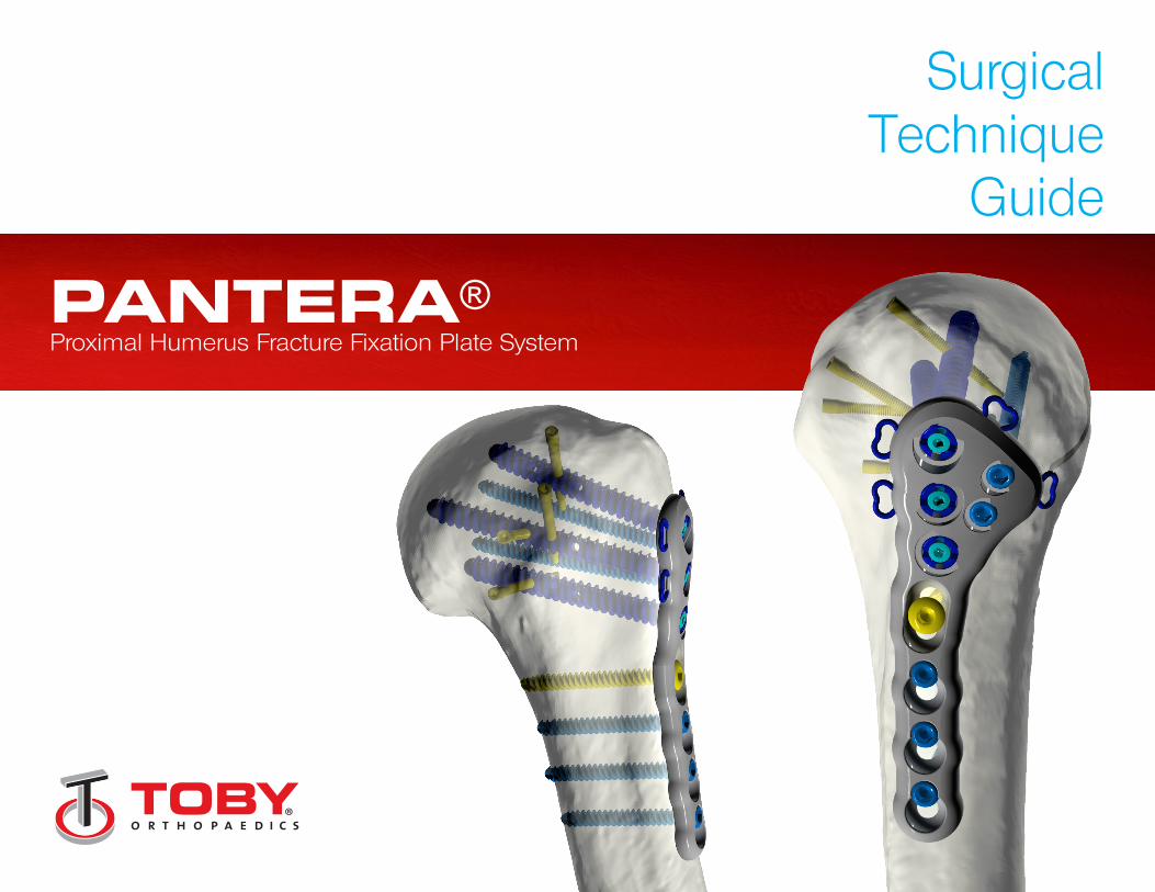
PANTERA®Proximal Humerus Fracture Fixation Plate System
1
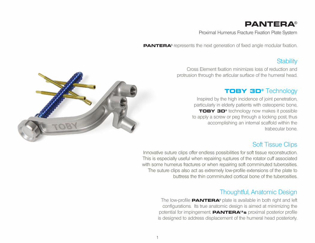
PANTERA®
Proximal Humerus Fracture Fixation Plate System
PANTERA® represents the next generation of fixed angle modular fixation.
StabilityCross Element fixation minimizes loss of reduction and
protrusion through the articular surface of the humeral head.
TOBY 3D® TechnologyInspired by the high incidence of joint penetration,
particularly in elderly patients with osteopenic bone, TOBY 3D® technology now makes it possible
to apply a screw or peg through a locking post, thus accomplishing an internal scaffold within the
trabecular bone.
Soft Tissue ClipsInnovative suture clips offer endless possibilities for soft tissue reconstruction.This is especially useful when repairing ruptures of the rotator cuff associated with some humerus fractures or when repairing soft comminuted tuberosities.
The suture clips also act as extremely low-profile extensions of the plate to buttress the thin comminuted cortical bone of the tuberosities.
Thoughtful, Anatomic DesignThe low-profile PANTERA® plate is available in both right and left configurations. Its true anatomic design is aimed at minimizing the
potential for impingement. PANTERA®’s proximal posterior profileis designed to address displacement of the humeral head posteriorly.
2
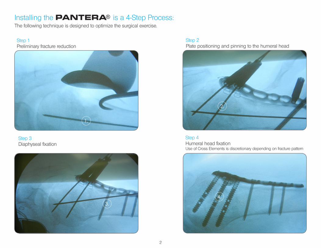
Installing the PANTERA® is a 4-Step Process:
Step 1Preliminary fracture reduction
Step 2Plate positioning and pinning to the humeral head
Step 3Diaphyseal fixation
Step 4Humeral head fixationUse of Cross Elements is discretionary depending on fracture pattern
The following technique is designed to optimize the surgical exercise.
1.
2.
3.4.
3
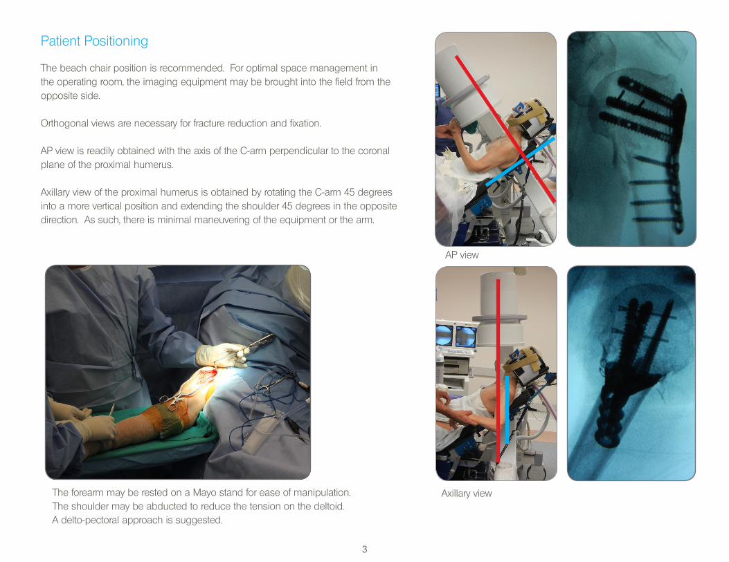
Patient Positioning
The beach chair position is recommended. For optimal space management in the operating room, the imaging equipment may be brought into the field from the opposite side.
Orthogonal views are necessary for fracture reduction and fixation.
AP view is readily obtained with the axis of the C-arm perpendicular to the coronal plane of the proximal humerus.
Axillary view of the proximal humerus is obtained by rotating the C-arm 45 degrees into a more vertical position and extending the shoulder 45 degrees in the opposite direction. As such, there is minimal maneuvering of the equipment or the arm.
Axillary view
AP view
The forearm may be rested on a Mayo stand for ease of manipulation.The shoulder may be abducted to reduce the tension on the deltoid. A delto-pectoral approach is suggested.
4
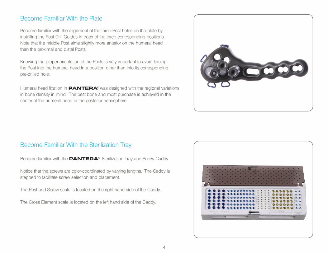
Become Familiar With the Plate
Become familiar with the alignment of the three Post holes on the plate by installing the Post Drill Guides in each of the three corresponding positions. Note that the middle Post aims slightly more anterior on the humeral head than the proximal and distal Posts.
Knowing the proper orientation of the Posts is very important to avoid forcing the Post into the humeral head in a position other than into its corresponding pre-drilled hole.
Humeral head fixation in PANTERA® was designed with the regional variations in bone density in mind. The best bone and most purchase is achieved in the center of the humeral head in the posterior hemisphere.
Become Familiar With the Sterilization Tray
Become familiar with the PANTERA® Sterilization Tray and Screw Caddy.
Notice that the screws are color-coordinated by varying lengths. The Caddy is stepped to facilitate screw selection and placement.
The Post and Screw scale is located on the right hand side of the Caddy.
The Cross Element scale is located on the left hand side of the Caddy.
5
Become Familiar With the Post Screw
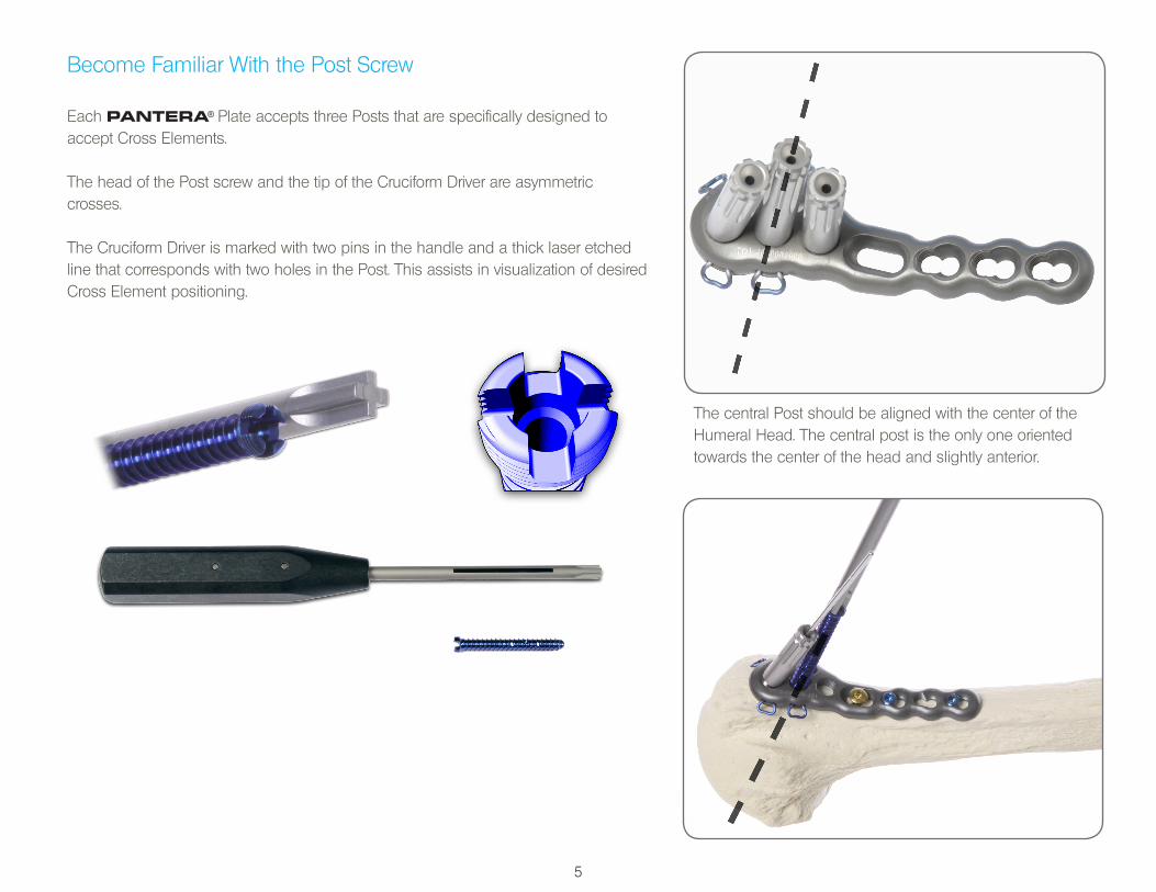
Each PANTERA® Plate accepts three Posts that are specifically designed to accept Cross Elements.
The head of the Post screw and the tip of the Cruciform Driver are asymmetric crosses.
The Cruciform Driver is marked with two pins in the handle and a thick laser etched line that corresponds with two holes in the Post. This assists in visualization of desired Cross Element positioning.
The central Post should be aligned with the center of the Humeral Head. The central post is the only one oriented towards the center of the head and slightly anterior.
6
Become Familiar with Cross Element Application
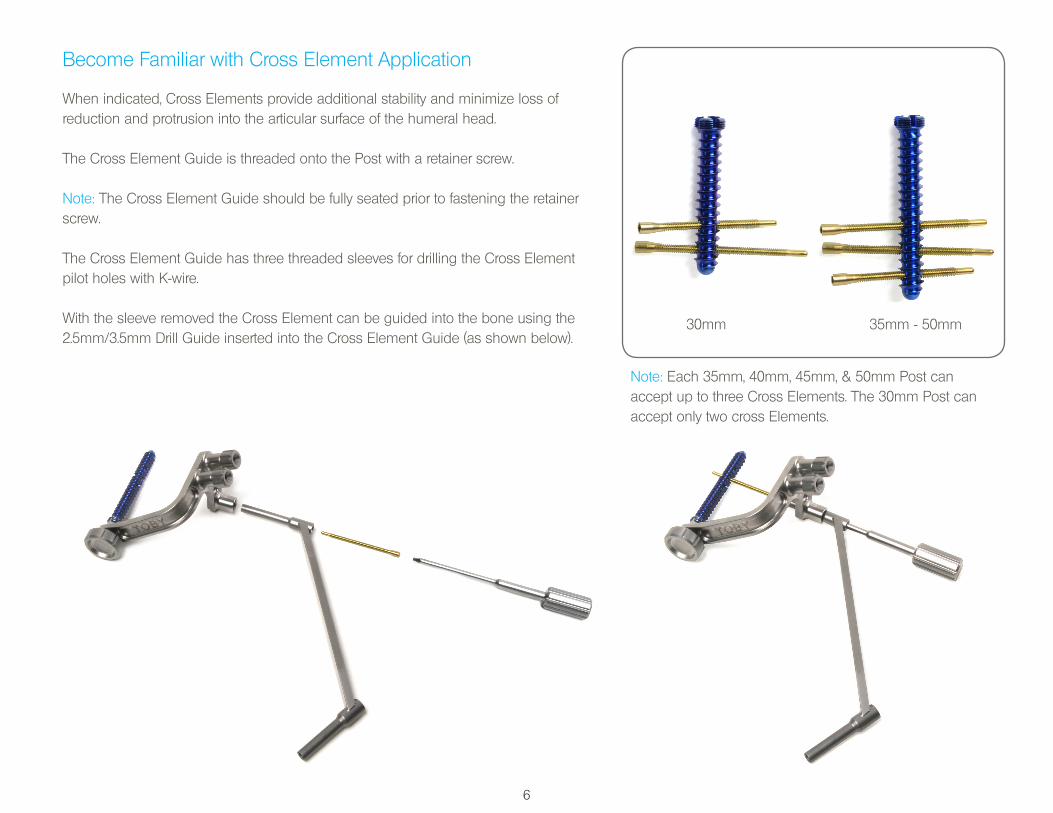
When indicated, Cross Elements provide additional stability and minimize loss of reduction and protrusion into the articular surface of the humeral head.
The Cross Element Guide is threaded onto the Post with a retainer screw.
Note: The Cross Element Guide should be fully seated prior to fastening the retainer screw.
The Cross Element Guide has three threaded sleeves for drilling the Cross Element pilot holes with K-wire.
With the sleeve removed the Cross Element can be guided into the bone using the 2.5mm/3.5mm Drill Guide inserted into the Cross Element Guide (as shown below).
Note: Each 35mm, 40mm, 45mm, & 50mm Post can accept up to three Cross Elements. The 30mm Post can accept only two cross Elements.
30mm 35mm - 50mm
7
Step 1Preliminary Fracture Reduction
Expose and debride the fracture. Make every effort to avoid stripping the soft tissue from the fracture fragments. The hematoma from the fracture site may be removed using suction. Use traction and direct manipulation to reduce the fracture. Re-establish the anatomical relationship between the articular surface and the humeral shaft by restoring both its angular alignment and retroversion.
Assure the tuberosities can be reduced to their proper locations. Suture may be applied to the comminuted bone of the tuberosities for the purposes of fracture reduction and fixation.
The metaphyseal void that becomes obvious after reduction of the fracture fragments may be filled with allograft or a suitable bone substitute.
Preliminary reduction may be maintained with K-wires placed where they do not interfere with the application of the plate.
Caution: Exercise care to avoid damaging the vasculature to the bone fragments.
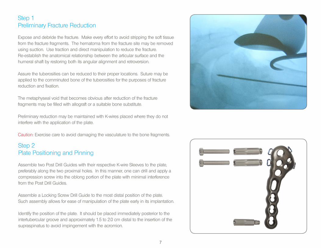
Step 2Plate Positioning and Pinning
Assemble two Post Drill Guides with their respective K-wire Sleeves to the plate, preferably along the two proximal holes. In this manner, one can drill and apply a compression screw into the oblong portion of the plate with minimal interference from the Post Drill Guides.
Assemble a Locking Screw Drill Guide to the most distal position of the plate. Such assembly allows for ease of manipulation of the plate early in its implantation.
Identify the position of the plate. It should be placed immediately posterior to the intertubercular groove and approximately 1.5 to 2.0 cm distal to the insertion of the supraspinatus to avoid impingement with the acromion.
8
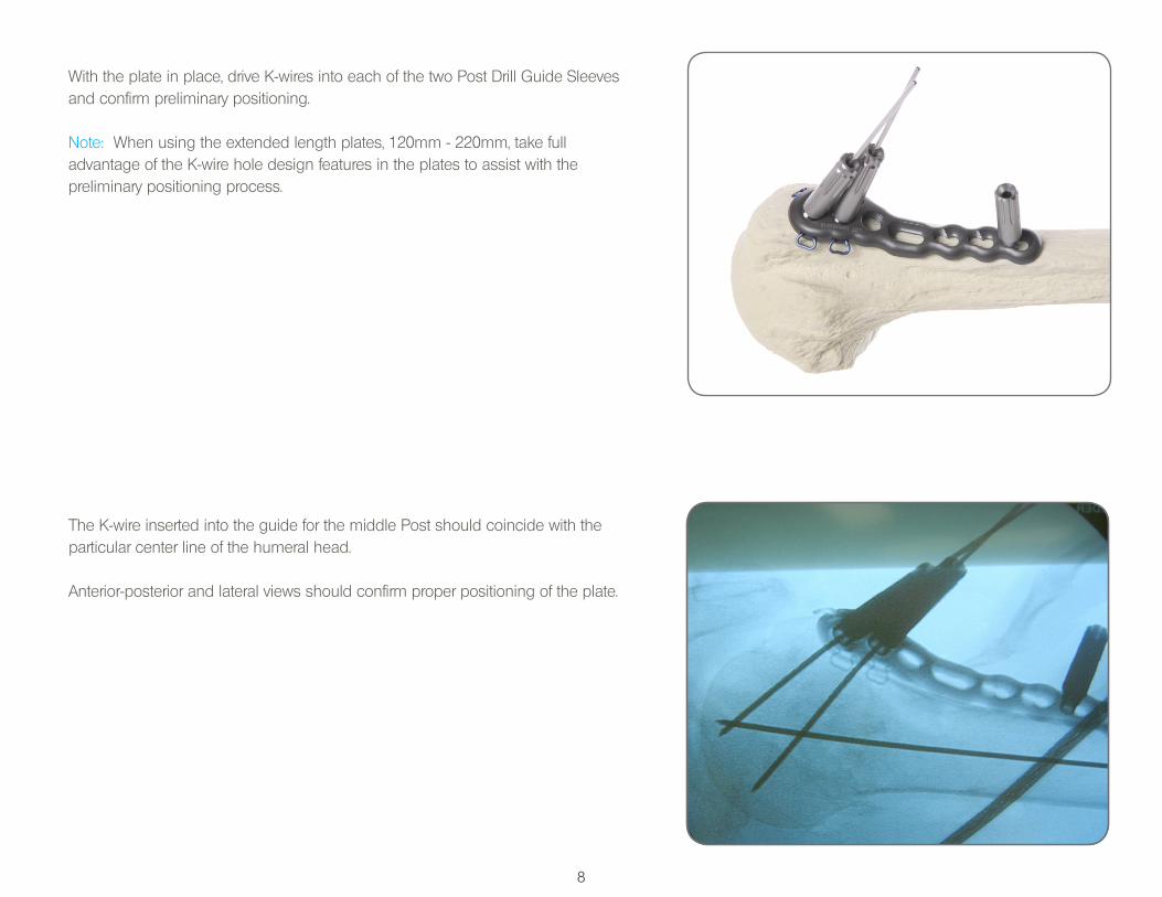
With the plate in place, drive K-wires into each of the two Post Drill Guide Sleeves and confirm preliminary positioning.
Note: When using the extended length plates, 120mm - 220mm, take full advantage of the K-wire hole design features in the plates to assist with the preliminary positioning process.
The K-wire inserted into the guide for the middle Post should coincide with theparticular center line of the humeral head.
Anterior-posterior and lateral views should confirm proper positioning of the plate.
9
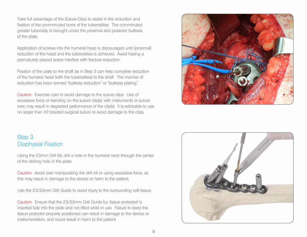
Take full advantage of the Suture Clips to assist in the reduction and fixation of the comminuted bone of the tuberosities. The comminuted greater tuberosity is brought under the proximal and posterior buttress of the plate.
Application of screws into the humeral head is discouraged until (proximal) reduction of the head and the tuberosities is achieved. Avoid having a prematurely placed screw interfere with fracture reduction.
Fixation of the plate to the shaft as in Step 3 can help complete reduction of the humeral head (with the tuberosities) to the shaft. The manner of reduction has been termed “buttress reduction” or “buttress plating.”
Caution: Exercise care to avoid damage to the suture clips. Use of excessive force or bending on the suture clip(s), with instruments or suture wire, may result in degraded performance of the clip(s). It is advisable to use no larger than #2 braided surgical suture to avoid damage to the clips.
Step 3Diaphysial Fixation
Using the 2.5mm Drill Bit, drill a hole in the humeral neck through the center of the oblong hole in the plate.
Caution: Avoid over manipulating the drill bit or using excessive force, asthis may result in damage to the device or harm to the patient.
Use the 2.5/3.5mm Drill Guide to avoid injury to the surrounding soft tissue.
Caution: Ensure that the 2.5/3.5mm Drill Guide (i.e. tissue protector) is inserted fully into the plate and not lifted while in use. Failure to keep thetissue protector properly positioned can result in damage to the device orinstrumentation, and could result in harm to the patient.
10
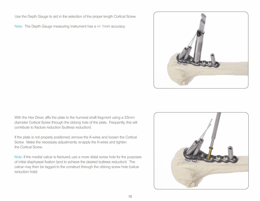
Use the Depth Gauge to aid in the selection of the proper length Cortical Screw.
Note: The Depth Gauge measuring instrument has a +/- 1mm accuracy.
With the Hex Driver, affix the plate to the humeral shaft fragment using a 3.5mm diameter Cortical Screw through the oblong hole of the plate. Frequently, this will contribute to fracture reduction (buttress reduction).
If the plate is not properly positioned, remove the K-wires and loosen the Cortical Screw. Make the necessary adjustments, re-apply the K-wires and tighten the Cortical Screw.
Note: If the medial calcar is fractured, use a more distal screw hole for the purposes of initial diaphyseal fixation (and to achieve the desired buttress reduction). The calcar may then be lagged to the construct through the oblong screw hole (calcar reduction hole).
11
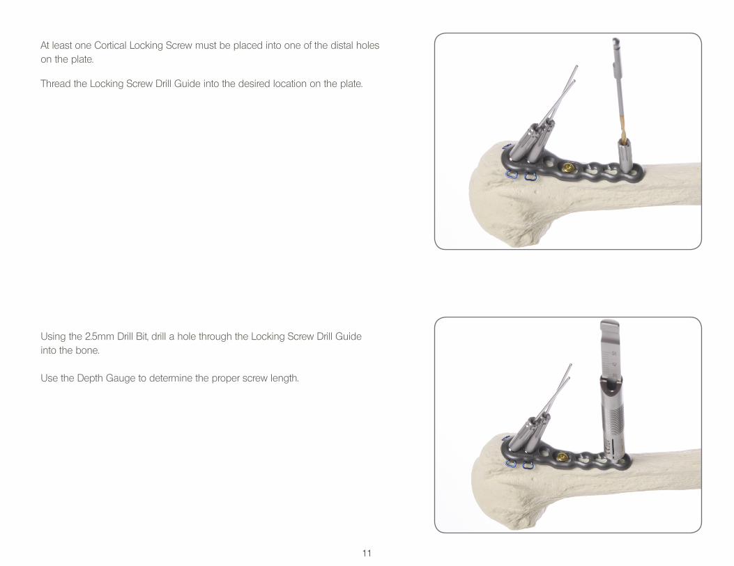
At least one Cortical Locking Screw must be placed into one of the distal holes on the plate.
Thread the Locking Screw Drill Guide into the desired location on the plate.
Using the 2.5mm Drill Bit, drill a hole through the Locking Screw Drill Guide into the bone.
Use the Depth Gauge to determine the proper screw length.
12
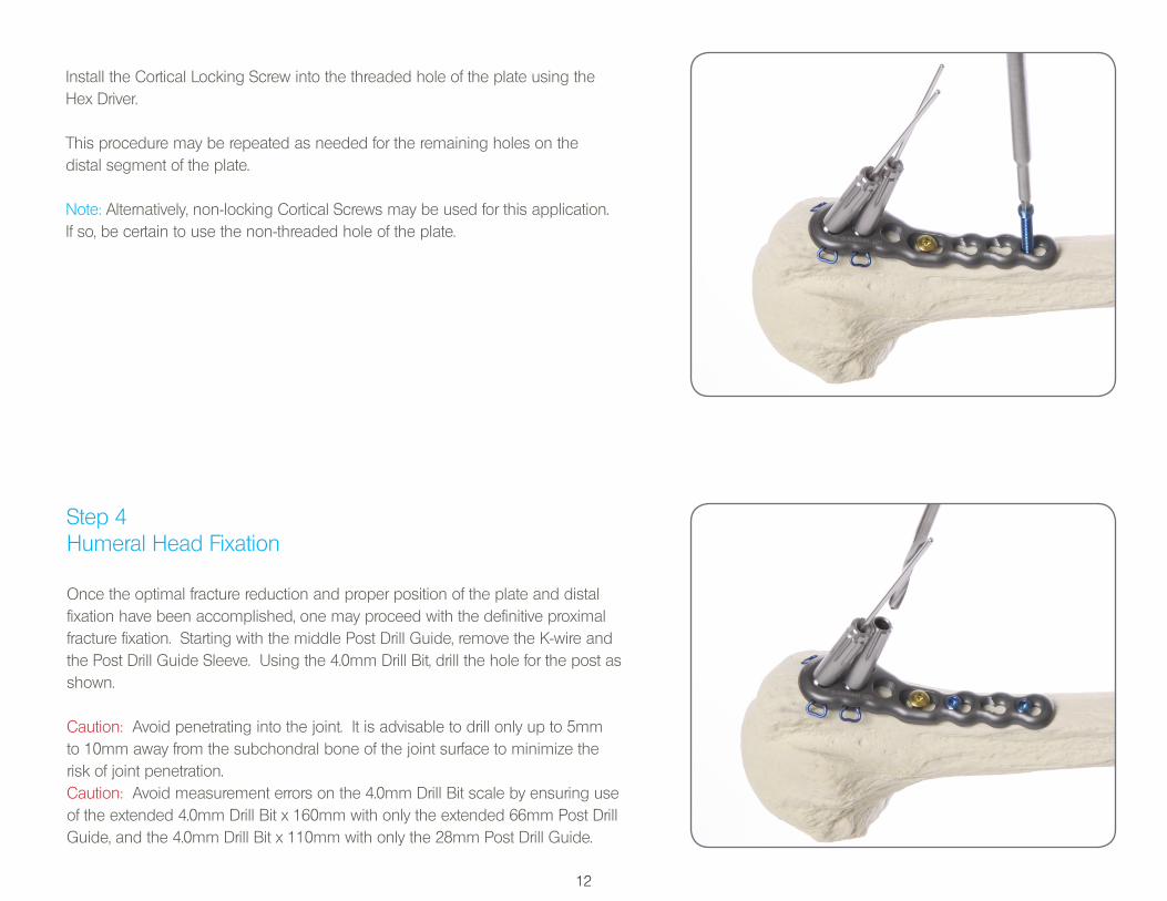
Install the Cortical Locking Screw into the threaded hole of the plate using the Hex Driver.
This procedure may be repeated as needed for the remaining holes on the distal segment of the plate.
Note: Alternatively, non-locking Cortical Screws may be used for this application. If so, be certain to use the non-threaded hole of the plate.
Step 4Humeral Head Fixation
Once the optimal fracture reduction and proper position of the plate and distal fixation have been accomplished, one may proceed with the definitive proximal fracture fixation. Starting with the middle Post Drill Guide, remove the K-wire and the Post Drill Guide Sleeve. Using the 4.0mm Drill Bit, drill the hole for the post as shown.
Caution: Avoid penetrating into the joint. It is advisable to drill only up to 5mm to 10mm away from the subchondral bone of the joint surface to minimize the risk of joint penetration.Caution: Avoid measurement errors on the 4.0mm Drill Bit scale by ensuring use of the extended 4.0mm Drill Bit x 160mm with only the extended 66mm Post Drill Guide, and the 4.0mm Drill Bit x 110mm with only the 28mm Post Drill Guide.
13
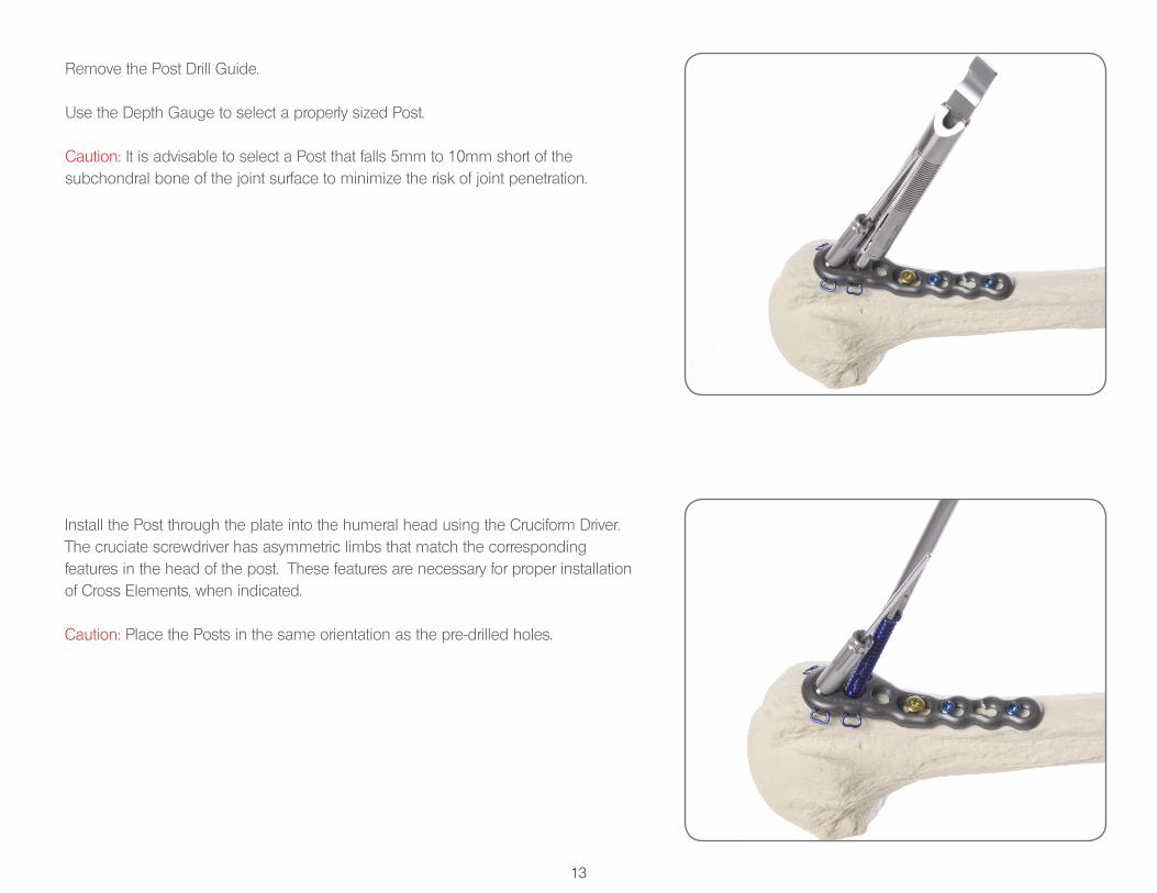
Remove the Post Drill Guide.
Use the Depth Gauge to select a properly sized Post.
Caution: It is advisable to select a Post that falls 5mm to 10mm short of the subchondral bone of the joint surface to minimize the risk of joint penetration.
Install the Post through the plate into the humeral head using the Cruciform Driver. The cruciate screwdriver has asymmetric limbs that match the correspondingfeatures in the head of the post. These features are necessary for proper installation of Cross Elements, when indicated.
Caution: Place the Posts in the same orientation as the pre-drilled holes.
14
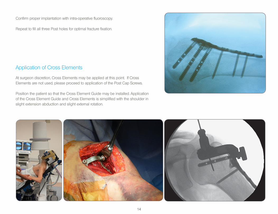
Application of Cross Elements
At surgeon discretion, Cross Elements may be applied at this point. If CrossElements are not used, please proceed to application of the Post Cap Screws.
Position the patient so that the Cross Element Guide may be installed. Application of the Cross Element Guide and Cross Elements is simplified with the shoulder in slight extension abduction and slight external rotation.
Confirm proper implantation with intra-operative fluoroscopy.
Repeat to fill all three Post holes for optimal fracture fixation.
15
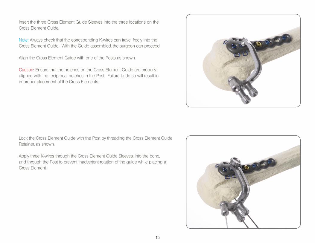
Lock the Cross Element Guide with the Post by threading the Cross Element Guide Retainer, as shown.
Apply three K-wires through the Cross Element Guide Sleeves, into the bone, and through the Post to prevent inadvertent rotation of the guide while placing a Cross Element.
Insert the three Cross Element Guide Sleeves into the three locations on the Cross Element Guide.
Note: Always check that the corresponding K-wires can travel freely into the Cross Element Guide. With the Guide assembled, the surgeon can proceed.
Align the Cross Element Guide with one of the Posts as shown.
Caution: Ensure that the notches on the Cross Element Guide are properly aligned with the reciprocal notches in the Post. Failure to do so will result in improper placement of the Cross Elements.
16
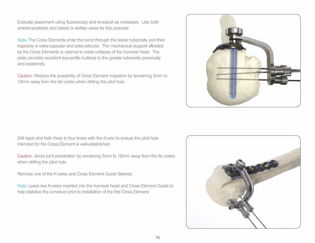
Evaluate placement using fluoroscopy and re-adjust as necessary. Use both anterior-posterior and lateral or axillary views for this purpose.
Note: The Cross Elements enter the bone through the lesser tuberosity and their trajectory is extra-capsular and extra-articular. The mechanical support afforded by the Cross Elements is optimal to resist collapse of the humeral head. The plate provides excellent low-profile buttress to the greater tuberosity proximally and posteriorly.
Caution: •Reduce the possibility of Cross Element migration by remaining 5mm to 10mm away from the far cortex when drilling the pilot hole.
Drill back and forth three to four times with the K-wire to ensure the pilot hole intended for the Cross Element is well-established.
Caution: •Avoid joint penetration by remaining 5mm to 10mm away from the far cortex when drilling the pilot hole.
Remove one of the K-wires and Cross Element Guide Sleeves.
Note: Leave two K-wires inserted into the humeral head and Cross Element Guide to help stabilize the construct prior to installation of the first Cross Element.

17
Install the Cross Elements, as shown. Ensure that the head of the Cross Element is below the surface of the humeral head.
Repeat up to three times per Post to fill the three holes available for articulation with Cross Elements.
Caution: The 30mm Post can accept a maximum of two Cross Elements due to its shorter length.
Note: The actual number of Cross Elements used is left to the discretion of the surgeon.
Note: An important benefit of using the Cross Elements is the fixation of the lesser tuberosity. A well-fixed lesser tuberosity provides additional mechanical buttress and biologic support to the humeral head. In addition, stabilization of the lesser tuberosity may play a role in the restoration of functional internal rotation.
Insert the Depth Gauge into the Cross Element Guide hole vacated by the Sleeve.
Caution: Do not advance the tip of the Depth Gauge into the bone. Only advance the Depth Gauge until it touches the humeral head cortex.
Select the proper length Cross Element by viewing the corresponding scale labeled “Cross Element Scale” on the cylindrical surface of the Depth Gauge. The scale includes four corresponding sizes of the Cross Elements: 20mm, 25mm, 30mm, and 35mm.
Note: If the scale points in between two such sizes, always choose the smaller size. The Depth Gauge CE scale has a +/- 2mm accuracy.
C.E.
Scale
20
25
30
35
18
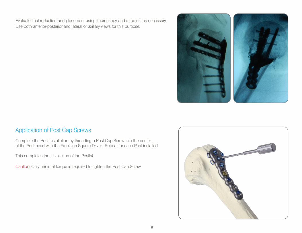
Evaluate final reduction and placement using fluoroscopy and re-adjust as necessary. Use both anterior-posterior and lateral or axillary views for this purpose.
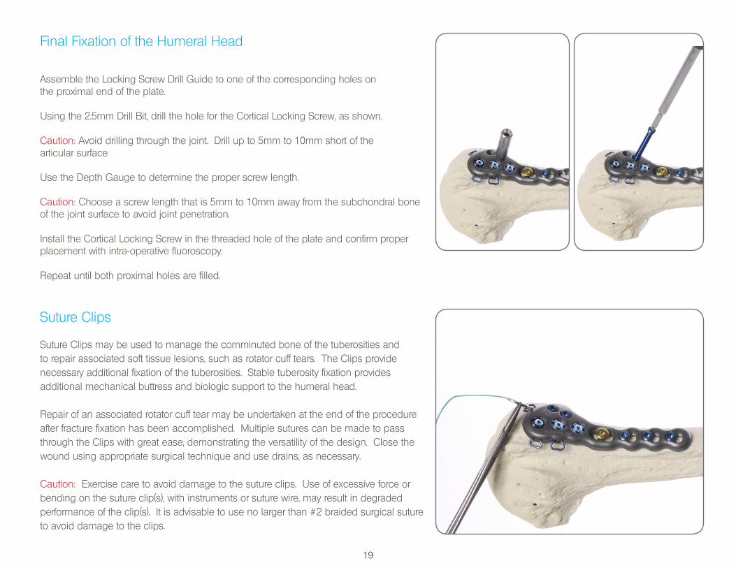
Application of Post Cap Screws
Complete the Post installation by threading a Post Cap Screw into the centerof the Post head with the Precision Square Driver. Repeat for each Post installed.
This completes the installation of the Post(s).
Caution: Only minimal torque is required to tighten the Post Cap Screw.
19
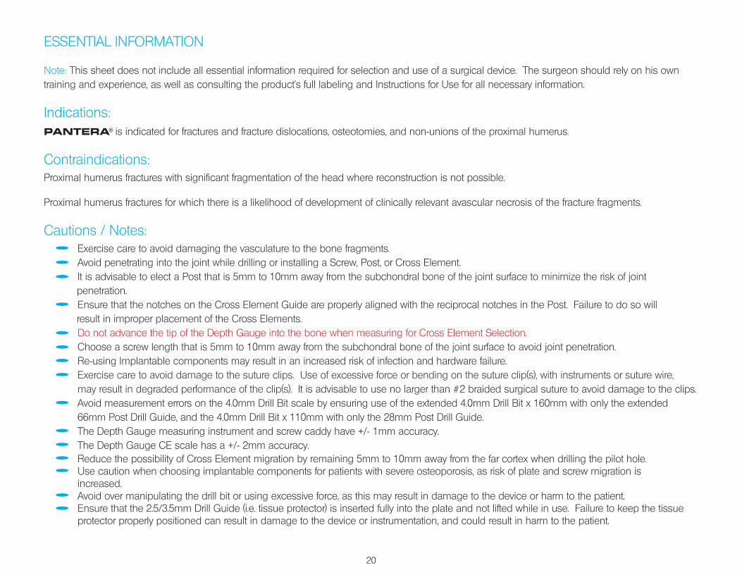
Suture Clips
Suture Clips may be used to manage the comminuted bone of the tuberosities and to repair associated soft tissue lesions, such as rotator cuff tears. The Clips provide necessary additional fixation of the tuberosities. Stable tuberosity fixation provides additional mechanical buttress and biologic support to the humeral head.
Repair of an associated rotator cuff tear may be undertaken at the end of the procedure after fracture fixation has been accomplished. Multiple sutures can be made to pass through the Clips with great ease, demonstrating the versatility of the design. Close the wound using appropriate surgical technique and use drains, as necessary.
Caution: Exercise care to avoid damage to the suture clips. Use of excessive force or bending on the suture clip(s), with instruments or suture wire, may result in degraded performance of the clip(s). It is advisable to use no larger than #2 braided surgical suture to avoid damage to the clips.
Final Fixation of the Humeral Head
Assemble the Locking Screw Drill Guide to one of the corresponding holes on the proximal end of the plate.
Using the 2.5mm Drill Bit, drill the hole for the Cortical Locking Screw, as shown.
Caution: Avoid drilling through the joint. Drill up to 5mm to 10mm short of the articular surface
Use the Depth Gauge to determine the proper screw length.
Caution: Choose a screw length that is 5mm to 10mm away from the subchondral bone of the joint surface to avoid joint penetration.
Install the Cortical Locking Screw in the threaded hole of the plate and confirm proper placement with intra-operative fluoroscopy.
Repeat until both proximal holes are filled.
20
ESSENTIAL INFORMATION
Note: This sheet does not include all essential information required for selection and use of a surgical device. The surgeon should rely on his own training and experience, as well as consulting the product’s full labeling and Instructions for Use for all necessary information.
Indications:PANTERA® is indicated for fractures and fracture dislocations, osteotomies, and non-unions of the proximal humerus.
Contraindications:Proximal humerus fractures with significant fragmentation of the head where reconstruction is not possible.
Proximal humerus fractures for which there is a likelihood of development of clinically relevant avascular necrosis of the fracture fragments.
Cautions / Notes: Exercise care to avoid damaging the vasculature to the bone fragments. Avoid penetrating into the joint while drilling or installing a Screw, Post, or Cross Element. It is advisable to elect a Post that is 5mm to 10mm away from the subchondral bone of the joint surface to minimize the risk of joint penetration. Ensure that the notches on the Cross Element Guide are properly aligned with the reciprocal notches in the Post. Failure to do so will result in improper placement of the Cross Elements. Do not advance the tip of the Depth Gauge into the bone when measuring for Cross Element Selection. Choose a screw length that is 5mm to 10mm away from the subchondral bone of the joint surface to avoid joint penetration. Re-using Implantable components may result in an increased risk of infection and hardware failure. Exercise care to avoid damage to the suture clips. Use of excessive force or bending on the suture clip(s), with instruments or suture wire, may result in degraded performance of the clip(s). It is advisable to use no larger than #2 braided surgical suture to avoid damage to the clips. Avoid measurement errors on the 4.0mm Drill Bit scale by ensuring use of the extended 4.0mm Drill Bit x 160mm with only the extended 66mm Post Drill Guide, and the 4.0mm Drill Bit x 110mm with only the 28mm Post Drill Guide. The Depth Gauge measuring instrument and screw caddy have +/- 1mm accuracy. The Depth Gauge CE scale has a +/- 2mm accuracy. Reduce the possibility of Cross Element migration by remaining 5mm to 10mm away from the far cortex when drilling the pilot hole. Use caution when choosing implantable components for patients with severe osteoporosis, as risk of plate and screw migration is increased. Avoid over manipulating the drill bit or using excessive force, as this may result in damage to the device or harm to the patient. Ensure that the 2.5/3.5mm Drill Guide (i.e. tissue protector) is inserted fully into the plate and not lifted while in use. Failure to keep the tissue protector properly positioned can result in damage to the device or instrumentation, and could result in harm to the patient.
21
ESSENTIAL INFORMATION
Adverse Effects:Potential complications / adverse events associated with the use of implantable shoulder plates include, but are not limited to, the following: Postoperative Pain (Shoulder) Screw Perforation Into Glenohumeral Joint Postoperative Discomfort Numbness Inflammation Humeral Head Collapse / Fracture Due To Aseptic Necrosis General Infection Avascular Necrosis
System Components and Ordering Information:Refer to the current revision of the PANTERA® system catalog for a full list of the available implants and accessories. Contact TOBY® customer service
to request additional information:
Toll Free: 866.979.TOBY (8629) Tel.: 1.406.556.3260 Fax: 1.305.768.0269 [email protected] www.TobyOrtho.com

TOBY PANTERA® Proximal Humerus Fracture Fixation Plate System has been cleared by the FDA. CE 0086 Copyright 2013. Toby Orthopaedics, Inc.. All rights reserved.
Toby Orthopaedics, Inc.Customer Service Division
2485 Manley RoadBozeman, MT 59715
USA
Toll Free: 866.979.TOBY (8629)Tel.: 1.406.556.3260Fax: 1.305.768.0269
This surgical technique is intended as an educational tool to assist a properly licensed medical professional in the usage of Toby Orthopaedics products, and is not meant to replace professional judgment as to product usage and technique.
Prior to use, medical professionals should consult the product’s Instructions for Use and rely on their own training and experience.
Printed in the USA. 50000058-7