Embed Size (px)
Citation preview
ProLiant 8000 Intel Pentium III Xeon700MHz ServersMaintenance and Service Guide
First Edition (April 2000)Part Number 187242-001Spare Part Number 192848-001Compaq Computer Corporation

Notice© 2000 Compaq Computer Corporation.
Compaq, Deskpro, Compaq Insight Manager, ProLiant, ROMPaq, SmartStart, NetFlex, and the Compaqlogo Registered in U.S. Patent and Trademark Office. Netelligent, is trademark and/or service mark ofCompaq Information Technologies Group, L.P. Microsoft, MS-DOS, Windows 2000, and Windows NTare registered trademarks of Microsoft Corporation in the United States and/or other countries. Intel andPentium are registered trademarks and Xeon is a trademark of Intel Corporation in the United States and/orother countries. UNIX is a registered trademark of The Open Group. All other product names mentionedherein may be trademarks or registered trademarks of their respective companies.
The information in this publication is subject to change without notice and is provided “AS IS” WITHOUTWARRANTY OF ANY KIND. THE ENTIRE RISK ARISING OUT OF THE USE OF THISINFORMATION REMAINS WITH RECIPIENT. IN NO EVENT SHALL COMPAQ BE LIABLE FORANY DIRECT, CONSEQUENTIAL, INCIDENTAL, SPECIAL, PUNITIVE OR OTHER DAMAGESWHATSOEVER (INCLUDING WITHOUT LIMITATION, DAMAGES FOR LOSS OF BUSINESSPROFITS, BUSINESS INTERRUPTION OR LOSS OF BUSINESS INFORMATION), EVEN IFCOMPAQ HAS BEEN ADVISED OF THE POSSIBILITY OF SUCH DAMAGES.The limited warranties for Compaq products are exclusively set forth in the documentationaccompanying such products. Nothing herein should be construed as constituting a further oradditional warranty.
Compaq ProLiant 8000 Intel Pentium III Xeon 700MHz ServersMaintenance and Service GuideFirst Edition (April 2000)Part Number 187242-001Spare Part Number 192848-001
Contents
About This GuideSymbols in Text.........................................................................................................viiCompaq Technician Notes .......................................................................................viiiWhere to Go for Additional Help .............................................................................viii
Integrated Management Display.......................................................................... ixTelephone Numbers ............................................................................................ ix
Chapter 1Illustrated Parts Catalog
Mechanical Parts Exploded View.............................................................................1-2Mechanical Spare Parts List .....................................................................................1-3System Components Exploded View .......................................................................1-5System Components Spare Parts List .......................................................................1-6
Chapter 2Removal and Replacement Procedures
Electrostatic Discharge Information.........................................................................2-1Symbols in Equipment .............................................................................................2-2System Interlocks .....................................................................................................2-3Preparation Procedures.............................................................................................2-3
Hot-Pluggable Parts...........................................................................................2-3Non-Hot-Pluggable Parts ..................................................................................2-3Turning Off the Server ......................................................................................2-4Rack Warnings ..................................................................................................2-5Servers Warnings and Precautions ....................................................................2-5
Top Access Panel .....................................................................................................2-6Right Side Access Panel ...........................................................................................2-7Left Side Access Panel .............................................................................................2-8Casters ......................................................................................................................2-9Front Air Baffle ......................................................................................................2-10Rear Air Baffle .......................................................................................................2-11Main Processor Air Baffle......................................................................................2-12Face Plates..............................................................................................................2-13
Removable Media Trim...................................................................................2-13Front Bezel ......................................................................................................2-14
Mass Storage and Removable Media Devices........................................................2-15Removable Media Blanking Panel ..................................................................2-16Removable Media Devices..............................................................................2-17Hard Drive Blanking Panels............................................................................2-18Hot-Plug Drive Replacement Guidelines ........................................................2-19Hot-Plug Drive Replacement Precautions.......................................................2-19
iv Compaq ProLiant 8000 Intel Pentium III Xeon 700MHz Servers Maintenance and Service Guide
Removal and Replacement Procedurescontinued
Drive Cage with Backplane Board .........................................................................2-21Power On/Standby Switch......................................................................................2-22Power Supply Lock Bar..........................................................................................2-24Power Supplies .......................................................................................................2-25
Power Supply Blanking Panel .........................................................................2-26Hot-Plug Power Supplies ................................................................................2-27
Power Backplane Board .........................................................................................2-29Fans ........................................................................................................................2-30
Hot-Plug Rear Processor Fan ..........................................................................2-30Redundant Rear Processor Fan........................................................................2-31Hot-Plug Front Processor Fan Assembly ........................................................2-32Redundant Front Processor Fan Assembly......................................................2-33Hot-Plug Front I/O Fans..................................................................................2-34
Hot-Plug I/O Fan Board .........................................................................................2-36SDRAM Memory ...................................................................................................2-37
Dual Inline Memory Modules .........................................................................2-37Memory Expansion Board...............................................................................2-38
Cache Accelerators.................................................................................................2-42Processors, Processor Power Modules, Processor Terminator Boards, ProcessorBoard with Tray......................................................................................................2-45
Processor .........................................................................................................2-46Processor Power Modules ...............................................................................2-50Processor Terminator Boards ..........................................................................2-54
Lower Processor Support Structure........................................................................2-55Upper Processor Support Structure ........................................................................2-57
Processor Board with Tray ..............................................................................2-58Integrated Management Display.............................................................................2-62I/O Expansion Slots and Related Components .......................................................2-63
Array Controllers with Extended SCSI ...........................................................2-67Extended SCSI Dividers..................................................................................2-70I/O Expansion Boards .....................................................................................2-71
Cabling Diagrams...................................................................................................2-72Hot-Plug Basket Insulator ......................................................................................2-74Expansion Board Guide..........................................................................................2-75PCI Hot Plug Interface Board.................................................................................2-76I/O Board................................................................................................................2-77External Battery......................................................................................................2-79
Chapter 3Diagnostics and Troubleshooting
Diagnostic Tools Utility Overview...........................................................................3-2Default Configuration...............................................................................................3-4
Default Configuration Messages .......................................................................3-4Inspect Utility....................................................................................................3-4
Utilities Access.........................................................................................................3-5Running Compaq Utilities.................................................................................3-5
Power-On Self-Test ..................................................................................................3-7POST Error Messages .......................................................................................3-7
Contents v
Diagnostics and Troubleshootingcontinued
Diagnostics Software..............................................................................................3-33Steps for Diagnostics.......................................................................................3-33100 – 199, Primary Processor Test Error Codes .............................................3-34200 – 299, Memory Test Error Codes .............................................................3-35300 – 399, Keyboard Test Error Codes ...........................................................3-37400 – 499, Parallel Printer Test Error Codes...................................................3-37500 – 599, Video Display Unit Test Error Codes............................................3-38600 – 699, Diskette Drive Test Error Codes ...................................................3-391100 – 1199, Serial Test Error Codes .............................................................3-401200 – 1299, Modem Communications Test Error Codes ..............................3-406000 – 6099, Compaq NIC Boards Test Error Codes .....................................3-416500 – 6599, SCSI Hard Drive Test Error Codes ...........................................3-416600 – 6699, SCSI/IDE CD-ROM Drive Test Error Codes............................3-426700 – 6799, SCSI Tape Drive Test Error Codes ...........................................3-428600 – 8699, Pointing Device Interface Test Error Codes ..............................3-43
Array Diagnostic Utility .........................................................................................3-44Starting ADU...................................................................................................3-44
Integrated Management Log...................................................................................3-65Multiple Ways of Viewing the Log.................................................................3-65Event List ........................................................................................................3-67Event Messages ...............................................................................................3-67
Rapid Error Recovery.............................................................................................3-70Automatic Server Recovery-2 .........................................................................3-70Server Health Logs..........................................................................................3-80ASR-2 Integrated Management Log Messages ...............................................3-80Storage Fault Recovery Tracking....................................................................3-83Storage Automatic Reconstruction..................................................................3-83Network Interface Fault Recovery Tracking ...................................................3-83Memory Fault Recovery Tracking ..................................................................3-83
Remote Service Features ........................................................................................3-84ROMPaq Error Recovery Options..........................................................................3-84
ROMPaq Disaster Recovery ...........................................................................3-85Redundant ROM Image Recovery ..................................................................3-86
Compaq Insight Manager .......................................................................................3-87Features of Compaq Insight Management.......................................................3-87Compaq Insight Management Software Architecture .....................................3-88
Chapter 4Connectors, Switches, and Status Indicators
Connectors................................................................................................................4-1Rear Panel .........................................................................................................4-2I/O Board...........................................................................................................4-3Processor Board.................................................................................................4-4
Switches ...................................................................................................................4-5Processor Board Bus/Core Frequency Ratio Switch Settings ...........................4-5Internal/External Battery Switch Settings .........................................................4-6
vi Compaq ProLiant 8000 Intel Pentium III Xeon 700MHz Servers Maintenance and Service Guide
Connectors, Switches, and Status Indicatorscontinued
Status Indicators .......................................................................................................4-7Front Panel System Interlock LED Status Indicators ........................................4-7I/O Board System Power Interlock LED Indicators ..........................................4-8Processor Board LED Status Indicators ..........................................................4-10Hot-Plug I/O Fan LED Status Indicators.........................................................4-11PCI Hot Plug LED Status Indicators ...............................................................4-12Hot-Plug Hard Drive LED Status Indicators...................................................4-13Power Supply LED Status Indicators ..............................................................4-14CD-ROM/Diskette Drive LED Status Indicators ............................................4-15
Chapter 5Specifications
System Unit ..............................................................................................................5-2Power Supply ...........................................................................................................5-3Dual Inline Memory Module....................................................................................5-41.44-MB Diskette Drive ...........................................................................................5-4IDE Max Slimline CD-ROM Drive..........................................................................5-5Hot-Plug Wide Ultra2 SCSI Hard Drives.................................................................5-7Hot-Plug Wide Ultra3 SCSI Hard Drives.................................................................5-8Smart Array 4250ES Controller ...............................................................................5-9NC3131 Fast Ethernet NIC 64 PCI Dual 10/100 Controller ..................................5-10
Index
About This Guide
This maintenance and service guide can be used for reference when servicing Compaq
ProLiant� 8000 servers.
WARNING: To reduce the risk of personal injury from electric shock and hazardous energylevels, only authorized service technicians should attempt to repair this equipment. Improperrepairs could create conditions that are hazardous.
IMPORTANT: The installation of options and servicing of this product shall be performed by individualswho are knowledgeable of the procedures, precautions, and hazards associated with equipmentcontaining hazardous energy circuits.
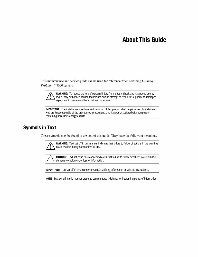
Symbols in TextThese symbols may be found in the text of this guide. They have the following meanings.
WARNING: Text set off in this manner indicates that failure to follow directions in the warningcould result in bodily harm or loss of life.
CAUTION: Text set off in this manner indicates that failure to follow directions could result indamage to equipment or loss of information.
IMPORTANT: Text set off in this manner presents clarifying information or specific instructions.
NOTE: Text set off in this manner presents commentary, sidelights, or interesting points of information.
viii Compaq ProLiant 8000 Intel Pentium III Xeon 700MHz Servers Maintenance and Service Guide
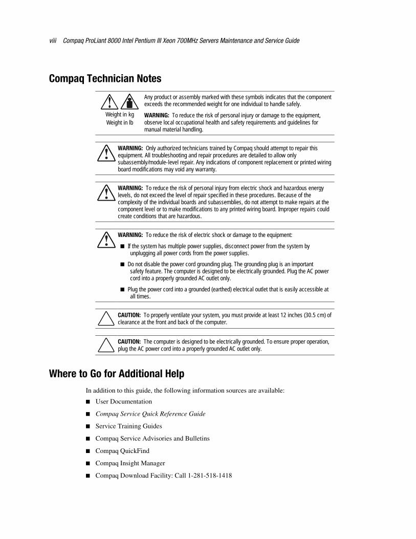
Compaq Technician Notes
Weight in kgWeight in lb
Any product or assembly marked with these symbols indicates that the componentexceeds the recommended weight for one individual to handle safely.
WARNING: To reduce the risk of personal injury or damage to the equipment,observe local occupational health and safety requirements and guidelines formanual material handling.
WARNING: Only authorized technicians trained by Compaq should attempt to repair thisequipment. All troubleshooting and repair procedures are detailed to allow onlysubassembly/module-level repair. Any indications of component replacement or printed wiringboard modifications may void any warranty.
WARNING: To reduce the risk of personal injury from electric shock and hazardous energylevels, do not exceed the level of repair specified in these procedures. Because of thecomplexity of the individual boards and subassemblies, do not attempt to make repairs at thecomponent level or to make modifications to any printed wiring board. Improper repairs couldcreate conditions that are hazardous.
WARNING: To reduce the risk of electric shock or damage to the equipment:
� If the system has multiple power supplies, disconnect power from the system byunplugging all power cords from the power supplies.
� Do not disable the power cord grounding plug. The grounding plug is an importantsafety feature. The computer is designed to be electrically grounded. Plug the AC powercord into a properly grounded AC outlet only.
� Plug the power cord into a grounded (earthed) electrical outlet that is easily accessible atall times.
CAUTION: To properly ventilate your system, you must provide at least 12 inches (30.5 cm) ofclearance at the front and back of the computer.
CAUTION: The computer is designed to be electrically grounded. To ensure proper operation,plug the AC power cord into a properly grounded AC outlet only.
Where to Go for Additional HelpIn addition to this guide, the following information sources are available:
� User Documentation
� Compaq Service Quick Reference Guide
� Service Training Guides
� Compaq Service Advisories and Bulletins
� Compaq QuickFind
� Compaq Insight Manager
� Compaq Download Facility: Call 1-281-518-1418

About This Guide ix
Integrated Management Display
All Compaq ProLiant 8000 servers include a Compaq Integrated Management Display (IMD),which is an integrated, 16 x 4 character display mounted on the front of the server. This displayprovides easy-to-use, menu-driven access to server information, including model number, LCDfirmware revision, and POST operations.
Telephone Numbers
For the name of your nearest Compaq authorized reseller:
� In the United States, call 1-800-345-1518
� In Canada, call 1-800-263-5868
For Compaq technical support:
� In the United States and Canada, call 1-800-386-2172
� For Compaq technical support phone numbers outside the United States and Canada, visitthe Compaq website at:
http://www.compaq.com
Chapter 1Illustrated Parts Catalog
This chapter provides the illustrated parts breakdown and a spare parts list for theProLiant 8000 server. Table 1-1 contains mechanical part descriptions and spare part numbers.Table 1-2 contains system component descriptions and spare part numbers
1-2 Compaq ProLiant 8000 Intel Pentium III Xeon 700MHz Servers Maintenance and Service Guide
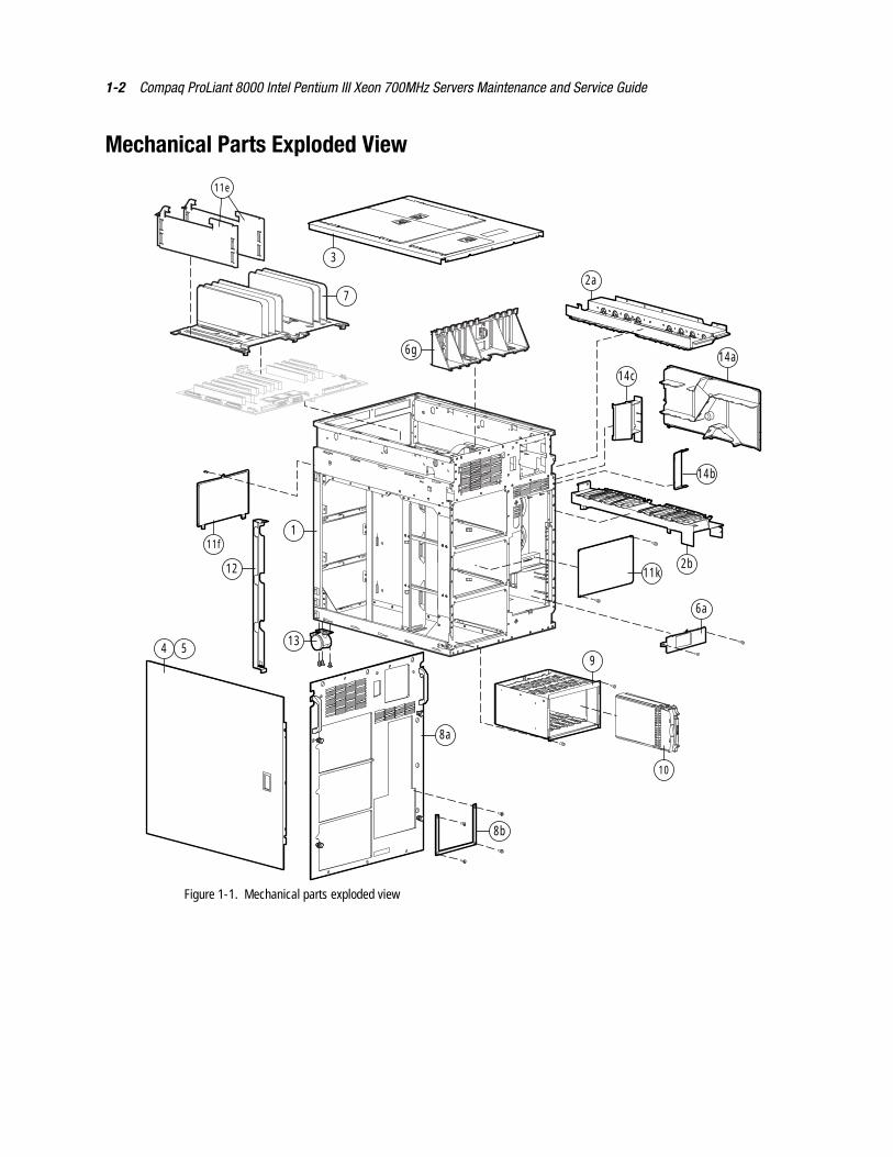
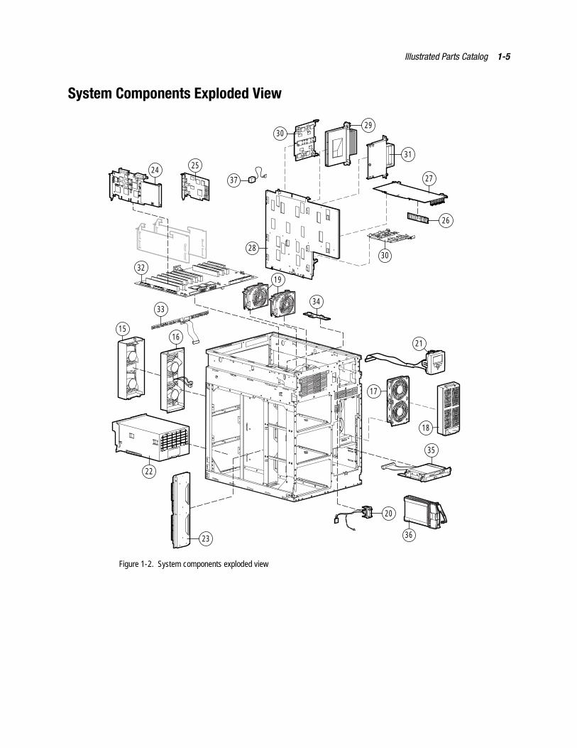
Mechanical Parts Exploded View
6g
1
13
11f
12
4
8b
7
8a
5
3
2b
10
6a
2a
9
11e
14a
14c
14b
11k
Figure 1-1. Mechanical parts exploded view
Illustrated Parts Catalog 1-3
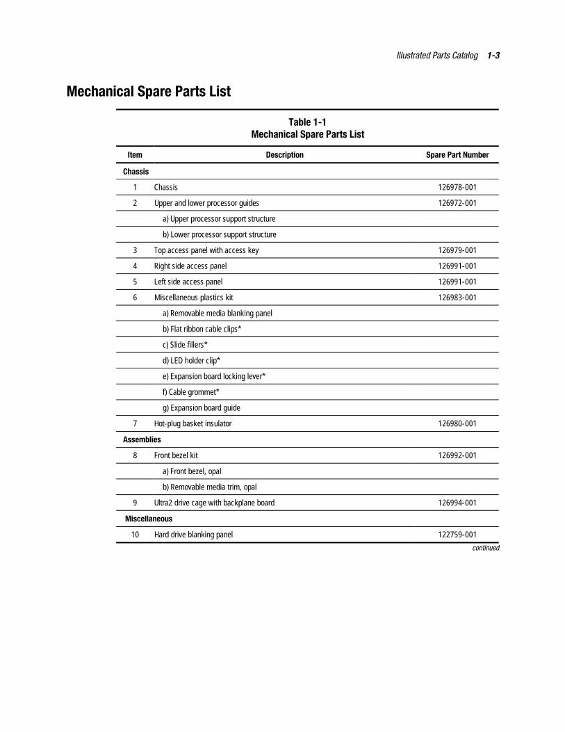
Mechanical Spare Parts List
Table 1-1Mechanical Spare Parts List
Item Description Spare Part Number
Chassis
1 Chassis 126978-001
2 Upper and lower processor guides 126972-001
a) Upper processor support structure
b) Lower processor support structure
3 Top access panel with access key 126979-001
4 Right side access panel 126991-001
5 Left side access panel 126991-001
6 Miscellaneous plastics kit 126983-001
a) Removable media blanking panel
b) Flat ribbon cable clips*
c) Slide fillers*
d) LED holder clip*
e) Expansion board locking lever*
f) Cable grommet*
g) Expansion board guide
7 Hot-plug basket insulator 126980-001
Assemblies
8 Front bezel kit 126992-001
a) Front bezel, opal
b) Removable media trim, opal
9 Ultra2 drive cage with backplane board 126994-001
Miscellaneous
10 Hard drive blanking panel 122759-001
continued
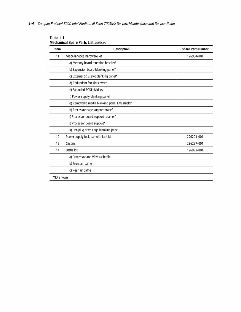
1-4 Compaq ProLiant 8000 Intel Pentium III Xeon 700MHz Servers Maintenance and Service Guide
Table 1-1Mechanical Spare Parts List continued
Item Description Spare Part Number
11 Miscellaneous hardware kit 126984-001
a) Memory board retention bracket*
b) Expansion board blanking panel*
c) External SCSI slot blanking panel*
d) Redundant fan slot cover*
e) Extended SCSI dividers
f) Power supply blanking panel
g) Removable media blanking panel EMI shield*
h) Processor cage support brace*
i) Processor board support retainer*
j) Processor board support*
k) Hot-plug drive cage blanking panel
12 Power supply lock bar with lock kit 296201-001
13 Casters 296227-001
14 Baffle kit 126993-001
a) Processor and VRM air baffle
b) Front air baffle
c) Rear air baffle
*Not shown
Illustrated Parts Catalog 1-5
System Components Exploded View
23
20
26
31
29
22
21
24
32
25
33
27
1615
35
19
36
37
30
3028
34
17
18
Figure 1-2. System components exploded view
1-6 Compaq ProLiant 8000 Intel Pentium III Xeon 700MHz Servers Maintenance and Service Guide
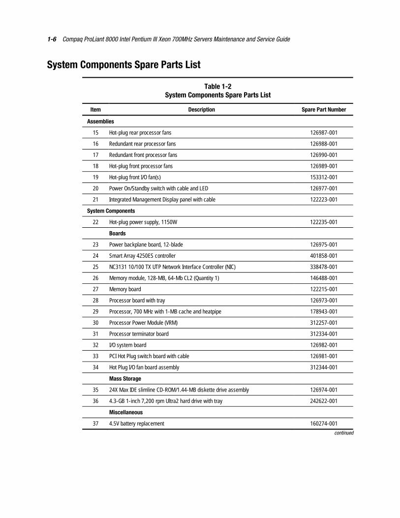
System Components Spare Parts List
Table 1-2System Components Spare Parts List
Item Description Spare Part Number
Assemblies
15 Hot-plug rear processor fans 126987-001
16 Redundant rear processor fans 126988-001
17 Redundant front processor fans 126990-001
18 Hot-plug front processor fans 126989-001
19 Hot-plug front I/O fan(s) 153312-001
20 Power On/Standby switch with cable and LED 126977-001
21 Integrated Management Display panel with cable 122223-001
System Components
22 Hot-plug power supply, 1150W 122235-001
Boards
23 Power backplane board, 12-blade 126975-001
24 Smart Array 4250ES controller 401858-001
25 NC3131 10/100 TX UTP Network Interface Controller (NIC) 338478-001
26 Memory module, 128-MB, 64-Mb CL2 (Quantity 1) 146488-001
27 Memory board 122215-001
28 Processor board with tray 126973-001
29 Processor, 700 MHz with 1-MB cache and heatpipe 178943-001
30 Processor Power Module (VRM) 312257-001
31 Processor terminator board 312334-001
32 I/O system board 126982-001
33 PCI Hot Plug switch board with cable 126981-001
34 Hot Plug I/O fan board assembly 312344-001
Mass Storage
35 24X Max IDE slimline CD-ROM/1.44-MB diskette drive assembly 126974-001
36 4.3-GB 1-inch 7,200 rpm Ultra2 hard drive with tray 242622-001
Miscellaneous
37 4.5V battery replacement 160274-001
continued
Illustrated Parts Catalog 1-7
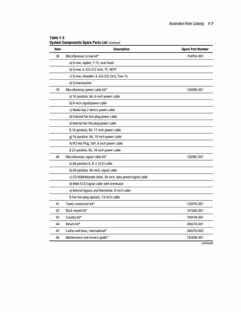
Table 1-2System Components Spare Parts List continued
Item Description Spare Part Number
38 Miscellaneous screw kit* 154954-001
a) Screw, taptite, T-15, oval-head
b) Screw, 6-32x.312 inch, TF, HI/TP
c) Screw, shoulder, 6-32x.335 inch, Torx-15
d) Screw/washer
39 Miscellaneous power cable kit* 126986-001
a) 10-position, 6A, 6-inch power cable
b) 8-inch signal/power cable
c) Media bay 2 device power cable
d) External fan hot-plug power cable
e) Internal fan hot-plug power cable
f) 16-position, 9A, 17-inch power cable
g) 18-position, 9A, 19-inch power cable
h) PCI Hot Plug, 50P, 8-inch power cable
I) 22-position, 9A, 18-inch power cable
40 Miscellaneous signal cable kit* 126985-001
a) 68-position A, B, C SCSI cable
b) 68-position, 46-inch, signal cable
c) CD-ROM/diskette drive, 30-inch, data power/signal cable
d) Wide SCSI signal cable with terminator
e) Internal bypass and thermistor, 8-inch cable
f) Fan hot-plug upstairs, 13-inch cable
41 Tower conversion kit* 126976-001
42 Rack mount kit* 161666-001
43 Country kit* 190418-001
44 Return kit* 306370-001
45 Carton and buns, international* 306370-002
46 Maintenance and service guide* 192848-001
continued
1-8 Compaq ProLiant 8000 Intel Pentium III Xeon 700MHz Servers Maintenance and Service Guide
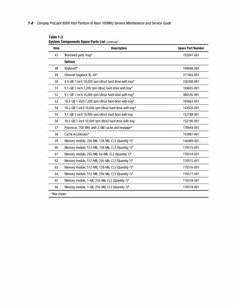
Table 1-2System Components Spare Parts List continued
Item Description Spare Part Number
47 Illustrated parts map* 192847-001
Options
48 Keyboard* 160648-XXX
49 Ethernet loopback RJ-45* 317465-001
50 4.3-GB 1-inch 10,000 rpm Ultra2 hard drive with tray* 336380-001
51 9.1-GB 1-inch 7,200 rpm Ultra2 hard drive with tray* 104665-001
52 9.1-GB 1-inch 10,000 rpm Ultra2 hard drive with tray* 386536-001
53 18.2-GB 1-inch 7,200 rpm Ultra2 hard drive with tray* 104663-001
54 18.2-GB 1-inch 10,000 rpm Ultra2 hard drive with tray* 143920-001
55 9.1-GB 1-inch 10,000 rpm Ultra3 hard drive with tray 152188-001
56 18.2-GB 1-inch 10,000 rpm Ultra3 hard drive with tray 152190-001
57 Processor, 700 MHz with 2-MB cache and heatpipe* 178944-001
58 Cache Accelerator* 143887-001
59 Memory module, 256-MB, 128-Mb, CL3 (Quantity 1)* 146489-001
60 Memory module, 512-MB, 128-Mb, CL2 (Quantity 1)* 170515-001
61 Memory module, 256-MB, 64-Mb, CL2 (Quantity 1)* 170514-001
62 Memory module, 512-MB, 256-Mb, CL2 (Quantity 1)* 170515-001
63 Memory module, 512-MB, 128-Mb, CL3 (Quantity 1)* 170516-001
64 Memory module, 512-MB, 256-Mb, CL3 (Quantity 1)* 170517-001
65 Memory module, 1-GB, 256-Mb, CL2 (Quantity 1)* 170518-001
66 Memory module, 1-GB, 256-Mb, CL3 (Quantity 1)* 170519-001
*Not shown
Chapter 2Removal and Replacement Procedures
This chapter provides subassembly/module-level removal and replacement procedures forCompaq ProLiant 8000 servers. After completing all necessary removal and replacementprocedures, run the Diagnostics program to verify that all components operate properly.
To service Compaq ProLiant 8000 servers, you might need the following:
� Flatblade screwdriver
� Phillips screwdriver
� Torx T-15 screwdriver
� From the Compaq SmartStart and Support Software CD:
� System Configuration Utility software
� Drive Array Advanced Diagnostics software
� Diagnostics software
Electrostatic Discharge InformationA discharge of static electricity can damage static-sensitive devices or microcircuitry. Properpackaging and grounding techniques are necessary precautions to prevent damage. To preventelectrostatic damage, observe the following precautions:
� Transport products in static-safe containers such as conductive tubes, bags, or boxes.
� Keep electrostatic-sensitive parts in their containers until they arrive at static-free stations.
� Cover workstations with approved static-dissipating material. Provide a wrist strapconnected to the work surface and properly grounded tools and equipment.
� Keep the work area free of nonconductive materials, such as plastic assembly aids andfoam packing.
� Make sure you are always properly grounded when touching a static-sensitive componentor assembly.
� Avoid touching pins, leads, or circuitry.
� Always place drives PCB assembly-side down.
� Use conductive field service tools.
2-2 Compaq ProLiant 8000 Intel Pentium III Xeon 700MHz Servers Maintenance and Service Guide
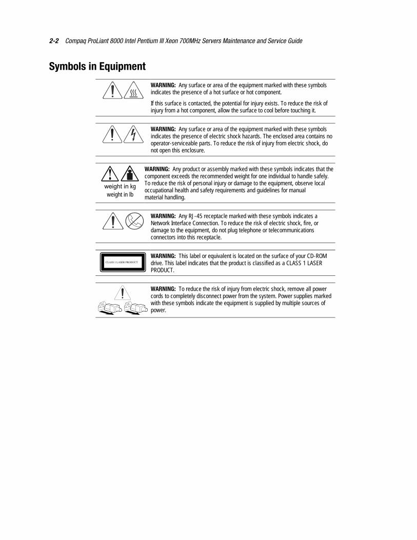
Symbols in Equipment
WARNING: Any surface or area of the equipment marked with these symbolsindicates the presence of a hot surface or hot component.
If this surface is contacted, the potential for injury exists. To reduce the risk ofinjury from a hot component, allow the surface to cool before touching it.
WARNING: Any surface or area of the equipment marked with these symbolsindicates the presence of electric shock hazards. The enclosed area contains nooperator-serviceable parts. To reduce the risk of injury from electric shock, donot open this enclosure.
weight in kgweight in lb
WARNING: Any product or assembly marked with these symbols indicates that thecomponent exceeds the recommended weight for one individual to handle safely.To reduce the risk of personal injury or damage to the equipment, observe localoccupational health and safety requirements and guidelines for manualmaterial handling.
WARNING: Any RJ-45 receptacle marked with these symbols indicates aNetwork Interface Connection. To reduce the risk of electric shock, fire, ordamage to the equipment, do not plug telephone or telecommunicationsconnectors into this receptacle.
CLASS 1 LASER PRODUCT
WARNING: This label or equivalent is located on the surface of your CD-ROMdrive. This label indicates that the product is classified as a CLASS 1 LASERPRODUCT.
WARNING: To reduce the risk of injury from electric shock, remove all powercords to completely disconnect power from the system. Power supplies markedwith these symbols indicate the equipment is supplied by multiple sources ofpower.
Removal and Replacement Procedures 2-3
System InterlocksCompaq ProLiant 8000 servers ship with system interlocks. System interlocks consist of threeLEDs providing a closed-loop checking mechanism for verifying proper cabling interconnectsbetween critical server components. These LEDs are located on both the I/O and the processorboards. They provide a visual aid to assist in isolating components to check if the server will notpower up because of a broken interlock chain. The I/O board is located directly beneath thePCI Hot Plug access doors under the top access panel. An amber system power LED on thefront of the server will illuminate whenever the interlock chain is broken.
Preparation Procedures
Hot-Pluggable Parts
Before beginning the removal of any serviceable parts, determine whether the part ishot-pluggable or non-hot-pluggable. If it is hot-pluggable, do not perform a power shutdown ofthe server. The access panels can be removed while the server is powered up without causing asystem shutdown. When the server is in Standby mode, portions of the power supply, auxiliarypower (+5V), and some internal circuitry will remain active.
Non-Hot-Pluggable Parts
If any serviceable parts are non-hot-pluggable, then the server must be shut down.Non-hot-pluggable parts include the processor, Processor Power Module, system board,memory board, and DIMMs. Refer to “Turning Off the Server” later in this chapter for completeinstructions.
WARNING: To reduce the risk of injury from electric shock, remove all powercords to completely disconnect power from the system. Power suppliesmarked with these symbols indicate the equipment is supplied by multiplesources of power.
2-4 Compaq ProLiant 8000 Intel Pentium III Xeon 700MHz Servers Maintenance and Service Guide
Turning Off the Server
The ProLiant 8000 server’s Power On/Standby switch does not shut off the system powercompletely. The switch functions as On and Standby, rather than On and Off. Standby moderemoves power from most of the electronics and the drives, but portions of the power supplyand some internal circuitry remain active.
IMPORTANT: To completely remove all power from the system, you must disconnect the power cordfrom the server. In systems with multiple power supplies, you must disconnect all power cords tocompletely remove power from the system.
IMPORTANT: It is not necessary to turn off the server to replace hot-plug devices, such as PCI Hot Plugpower supplies or hot-plug fans.
NOTE: It is necessary to be knowledgeable of electrostatic discharge information before performing thepreparation procedures. For electrostatic discharge information, see “Electrostatic DischargeInformation” earlier in this chapter.
Before beginning any removal and replacement procedure for non-hot-plug devices:
1. Press the Power On/Standby switch to Standby mode. This disables the main powersupply output and provides auxiliary power (+5V) to the server. Standby does not disablemain AC power.
2. Verify that the system LED on the front panel, near the Power On/Standby switch, is offand that the fan noise abates.
3. Disconnect all power cords from the server.
4. For some removal and replacement procedures, you must remove the server from the rackand place it on a sturdy table or workbench. Refer to the Compaq ProLiant 8000 Setupand Installation Guide for instructions.
46 – 109 kg100 – 240 lb
WARNING: To reduce the risk of personal injury or damage to the equipment:
� Observe local Occupational Safety requirements and guidelines for heavyequipment handling.
� Obtain adequate assistance to lift and stabilize the product during installation orremoval.
� Remove all pluggable power supplies and modules to reduce the weight of theproduct.
� Stabilize the server by keeping the unit on the rails.
WARNING: Because the rack allows you to stack computer components on a vertical ratherthan horizontal plane, you must take precautions to provide for rack stability and safety. Theseprecautions also protect both personnel and property. Follow all cautions and warningsthroughout the installation instructions that came with the server.
Removal and Replacement Procedures 2-5
WARNING: To reduce the risk of electric shock or damage to the equipment:
� If the system has multiple power supplies, disconnect power from the system byunplugging all power cords from the power supplies.
� Do not disable the power cord grounding plug. The grounding plug is an importantsafety feature.
� Plug the power cord into a grounded (earthed) electric outlet that is easily accessible atall times.
Rack Warnings
WARNING: To reduce the risk of personal injury or damage to the equipment, be sure that:
� The leveling jacks are extended to the floor.
� The full weight of the rack rests on the leveling jacks.
� The stabilizers are attached to the rack if it is a single-rack installation.
� The racks are coupled together in multiple-rack installations.
� The rack is adequately stabilized before extending a component outside the rack.
� One component is extended at a time.
WARNING: To reduce the risk of electric shock or damage to the equipment:
� Do not disable the power cord grounding plug. The grounding plug is an important safetyfeature.
� Plug the power cord into a grounded (earthed) electric outlet that is easily accessible at alltimes.
� Install the power supply before connecting the power cord to the power supply.
� Unplug the power cord before removing the power supply from the server.
� If the system has multiple power supplies, disconnect power from the system byunplugging all power cords from the power supplies.
CAUTION: Compaq ProLiant 8000 servers must always be operated with the system unit coveron. Proper cooling will not be achieved if the system unit cover is removed.
Servers Warnings and Precautions
WARNING: To reduce the risk of personal injury from hot surfaces, allow the internalsystem components to cool before touching them.
CAUTION: Protect the server from power fluctuations and temporary interruptions with aregulating uninterruptible power supply (UPS). This device protects the hardware from damagecaused by power surges and voltage spikes and keeps the system in operation during apower failure.
2-6 Compaq ProLiant 8000 Intel Pentium III Xeon 700MHz Servers Maintenance and Service Guide
Top Access Panel
WARNING: To reduce the risk of personal injury from hot surfaces, allow the internalsystem components to cool before touching them.
CAUTION: When the server is powered up, the access panel must be installed for propersystem cooling. Otherwise, component stress and permanent damage may result.
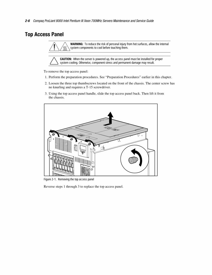
To remove the top access panel:
1. Perform the preparation procedures. See “Preparation Procedures” earlier in this chapter.
2. Loosen the three top thumbscrews located on the front of the chassis. The center screw hasno knurling and requires a T-15 screwdriver.
3. Using the top access panel handle, slide the top access panel back. Then lift it fromthe chassis.
Figure 2-1. Removing the top access panel
Reverse steps 1 through 3 to replace the top access panel.
Removal and Replacement Procedures 2-7
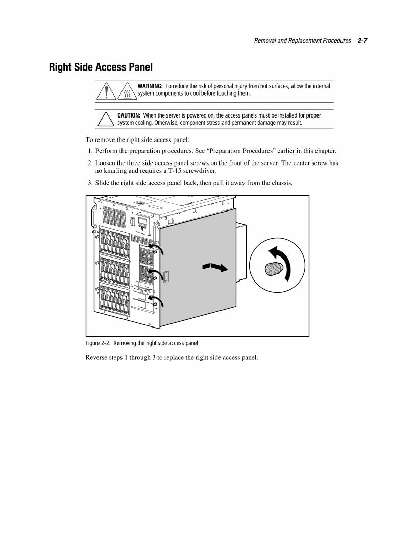
Right Side Access Panel
WARNING: To reduce the risk of personal injury from hot surfaces, allow the internalsystem components to cool before touching them.
CAUTION: When the server is powered on, the access panels must be installed for propersystem cooling. Otherwise, component stress and permanent damage may result.
To remove the right side access panel:
1. Perform the preparation procedures. See “Preparation Procedures” earlier in this chapter.
2. Loosen the three side access panel screws on the front of the server. The center screw hasno knurling and requires a T-15 screwdriver.
3. Slide the right side access panel back, then pull it away from the chassis.
Figure 2-2. Removing the right side access panel
Reverse steps 1 through 3 to replace the right side access panel.
2-8 Compaq ProLiant 8000 Intel Pentium III Xeon 700MHz Servers Maintenance and Service Guide
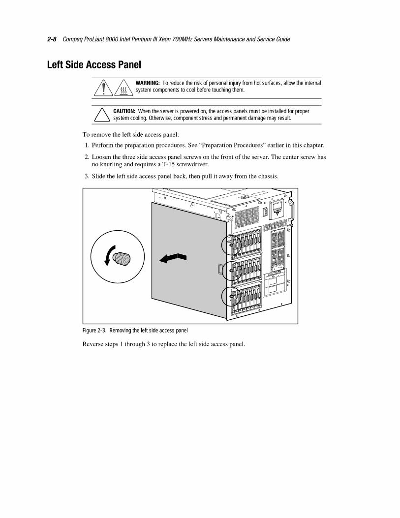
Left Side Access Panel
WARNING: To reduce the risk of personal injury from hot surfaces, allow the internalsystem components to cool before touching them.
CAUTION: When the server is powered on, the access panels must be installed for propersystem cooling. Otherwise, component stress and permanent damage may result.
To remove the left side access panel:
1. Perform the preparation procedures. See “Preparation Procedures” earlier in this chapter.
2. Loosen the three side access panel screws on the front of the server. The center screw hasno knurling and requires a T-15 screwdriver.
3. Slide the left side access panel back, then pull it away from the chassis.
Figure 2-3. Removing the left side access panel
Reverse steps 1 through 3 to replace the left side access panel.
Removal and Replacement Procedures 2-9
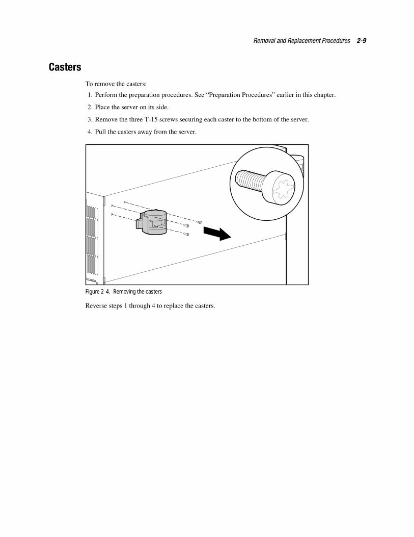
CastersTo remove the casters:
1. Perform the preparation procedures. See “Preparation Procedures” earlier in this chapter.
2. Place the server on its side.
3. Remove the three T-15 screws securing each caster to the bottom of the server.
4. Pull the casters away from the server.
Figure 2-4. Removing the casters
Reverse steps 1 through 4 to replace the casters.
2-10 Compaq ProLiant 8000 Intel Pentium III Xeon 700MHz Servers Maintenance and Service Guide
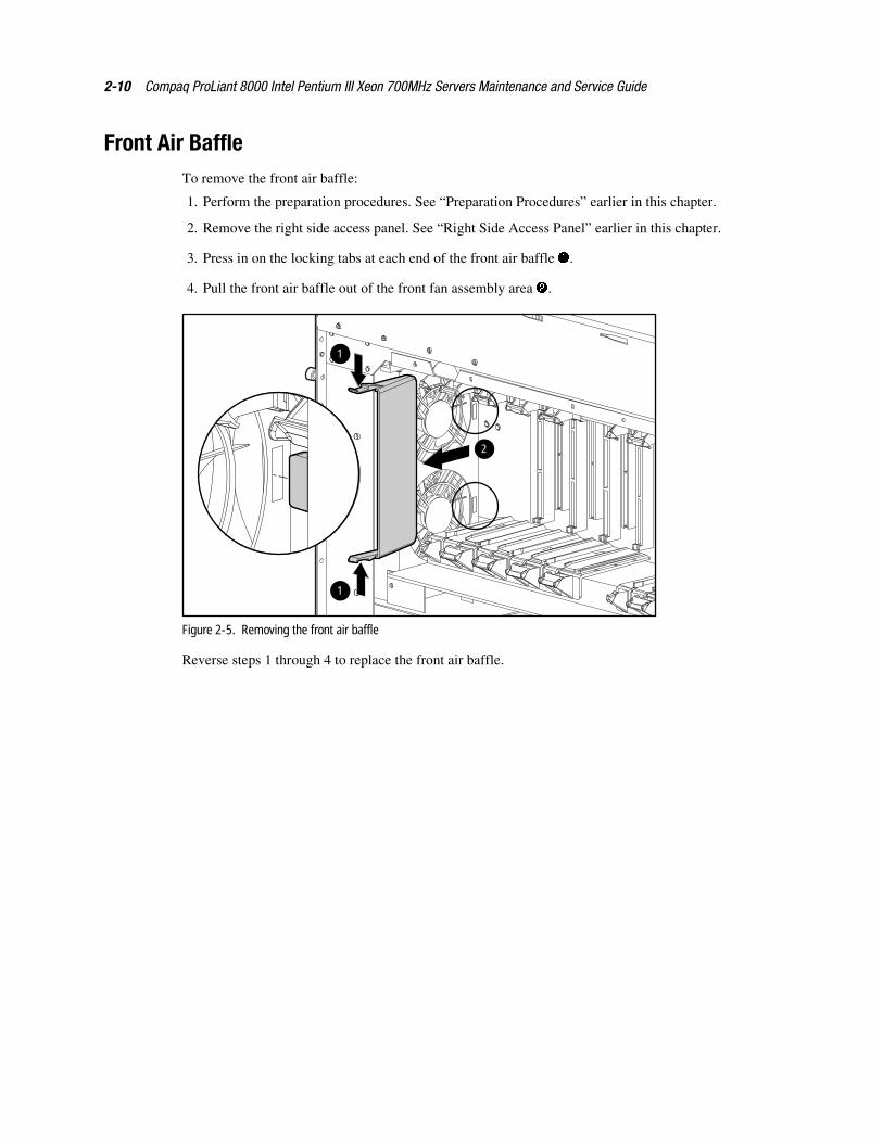
Front Air BaffleTo remove the front air baffle:
1. Perform the preparation procedures. See “Preparation Procedures” earlier in this chapter.
2. Remove the right side access panel. See “Right Side Access Panel” earlier in this chapter.
3. Press in on the locking tabs at each end of the front air baffle �.
4. Pull the front air baffle out of the front fan assembly area �.
1
1
2
Figure 2-5. Removing the front air baffle
Reverse steps 1 through 4 to replace the front air baffle.
Removal and Replacement Procedures 2-11
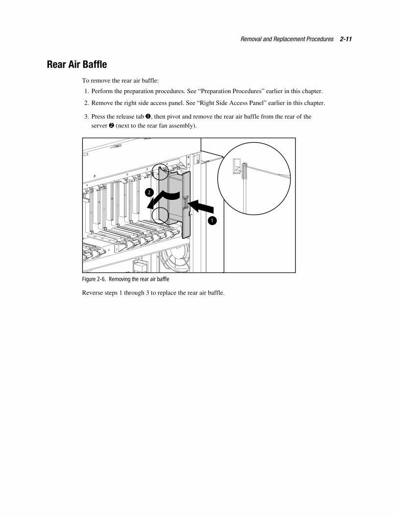
Rear Air BaffleTo remove the rear air baffle:
1. Perform the preparation procedures. See “Preparation Procedures” earlier in this chapter.
2. Remove the right side access panel. See “Right Side Access Panel” earlier in this chapter.
3. Press the release tab �, then pivot and remove the rear air baffle from the rear of the
server � (next to the rear fan assembly).
1
2
Figure 2-6. Removing the rear air baffle
Reverse steps 1 through 3 to replace the rear air baffle.
2-12 Compaq ProLiant 8000 Intel Pentium III Xeon 700MHz Servers Maintenance and Service Guide
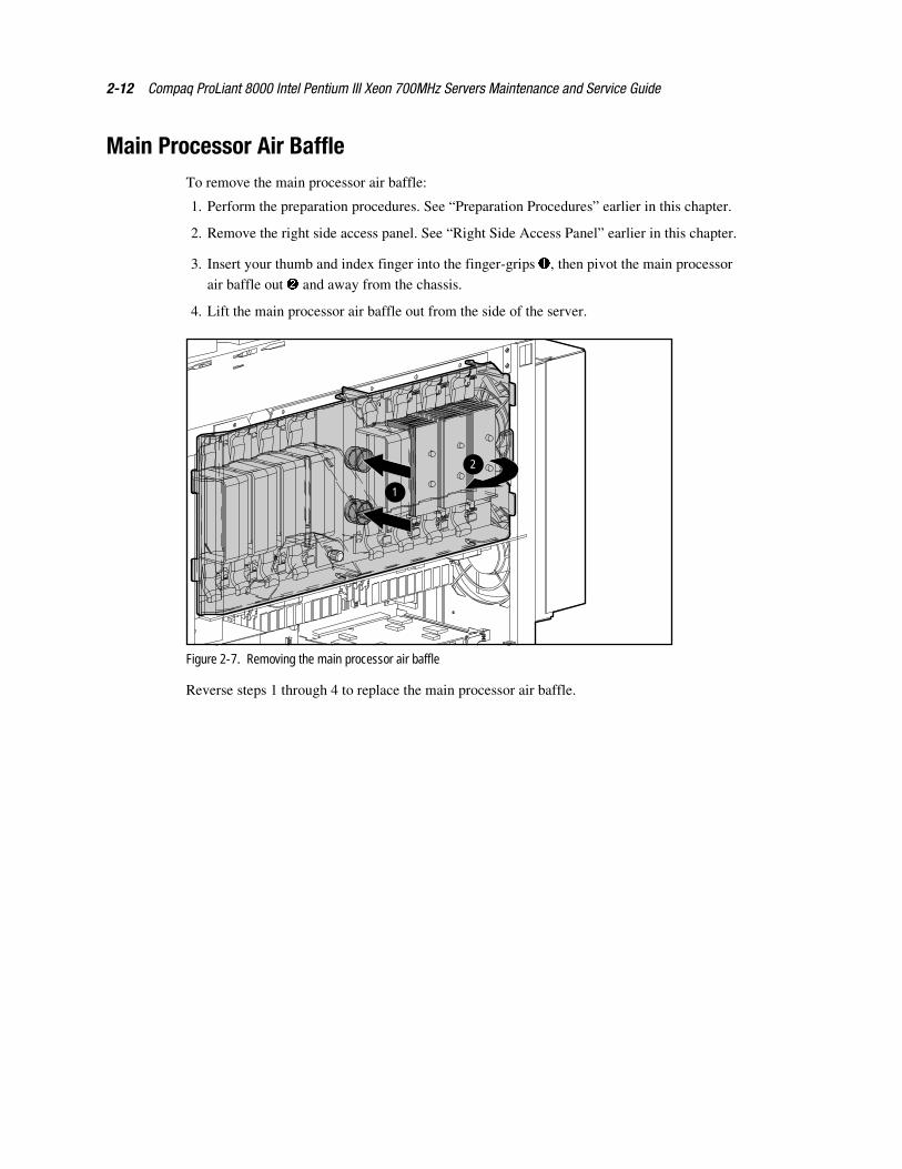
Main Processor Air BaffleTo remove the main processor air baffle:
1. Perform the preparation procedures. See “Preparation Procedures” earlier in this chapter.
2. Remove the right side access panel. See “Right Side Access Panel” earlier in this chapter.
3. Insert your thumb and index finger into the finger-grips �, then pivot the main processor
air baffle out � and away from the chassis.
4. Lift the main processor air baffle out from the side of the server.
1
2
Figure 2-7. Removing the main processor air baffle
Reverse steps 1 through 4 to replace the main processor air baffle.
Removal and Replacement Procedures 2-13
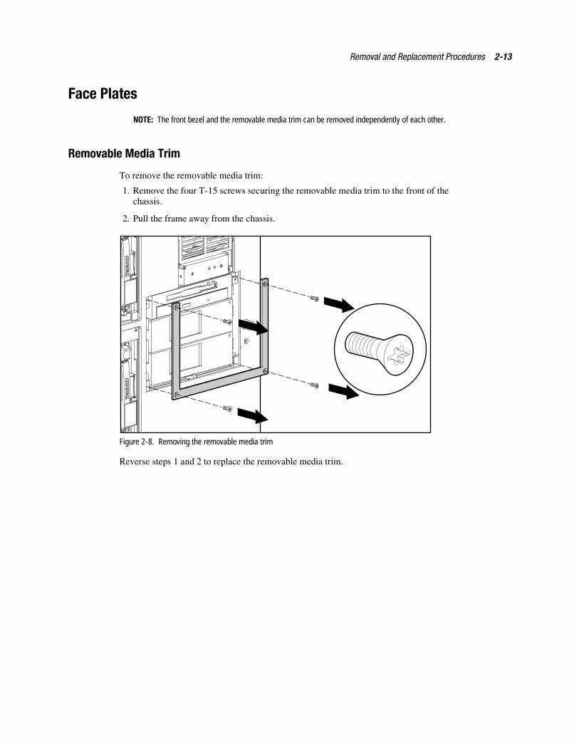
Face Plates
NOTE: The front bezel and the removable media trim can be removed independently of each other.
Removable Media Trim
To remove the removable media trim:
1. Remove the four T-15 screws securing the removable media trim to the front of thechassis.
2. Pull the frame away from the chassis.
Figure 2-8. Removing the removable media trim
Reverse steps 1 and 2 to replace the removable media trim.
2-14 Compaq ProLiant 8000 Intel Pentium III Xeon 700MHz Servers Maintenance and Service Guide
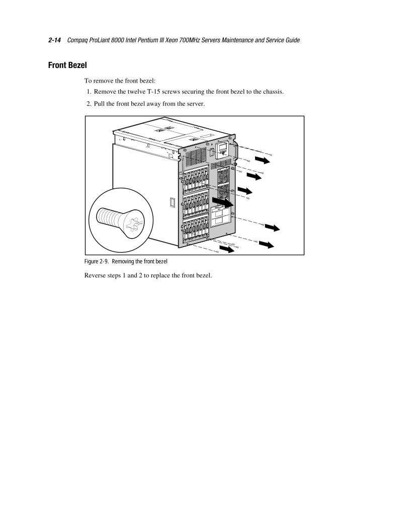
Front Bezel
To remove the front bezel:
1. Remove the twelve T-15 screws securing the front bezel to the chassis.
2. Pull the front bezel away from the server.
Figure 2-9. Removing the front bezel
Reverse steps 1 and 2 to replace the front bezel.
Removal and Replacement Procedures 2-15
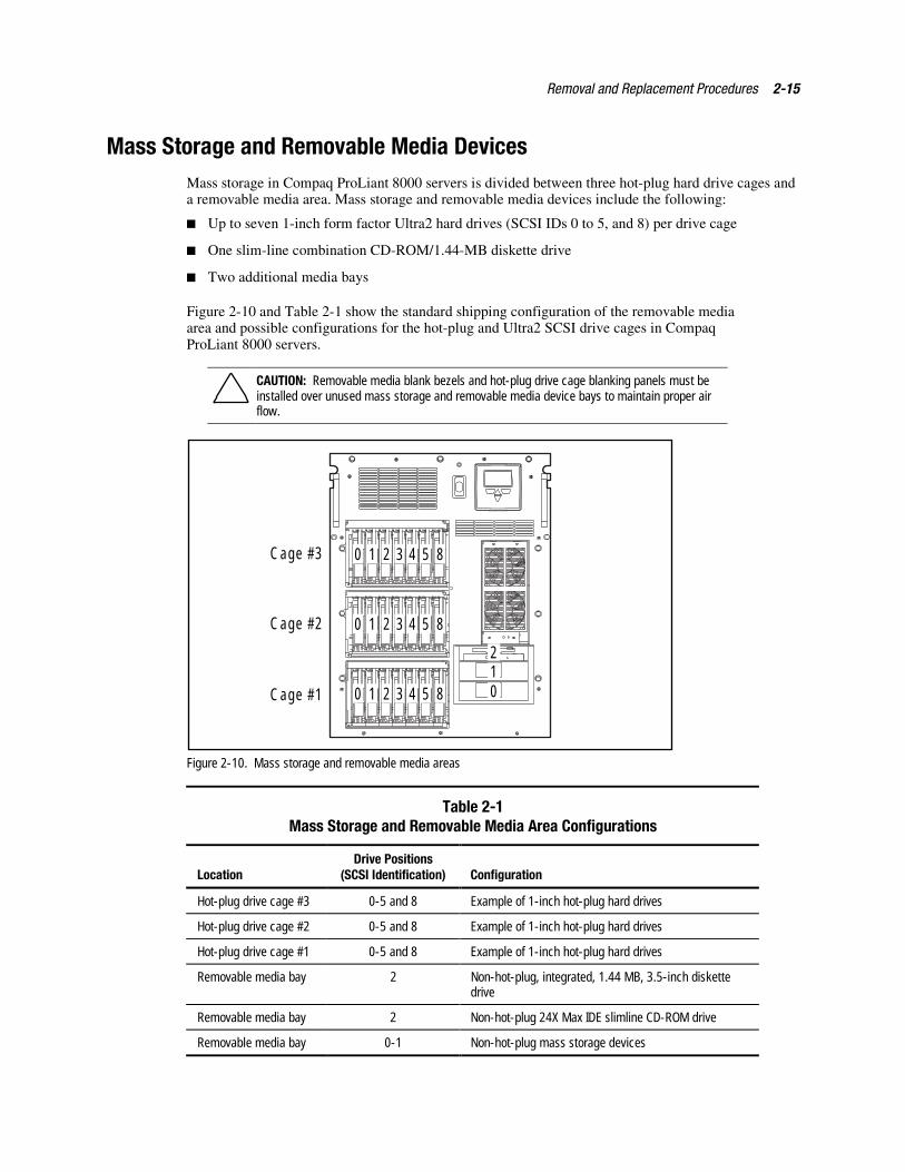
Mass Storage and Removable Media DevicesMass storage in Compaq ProLiant 8000 servers is divided between three hot-plug hard drive cages anda removable media area. Mass storage and removable media devices include the following:
� Up to seven 1-inch form factor Ultra2 hard drives (SCSI IDs 0 to 5, and 8) per drive cage
� One slim-line combination CD-ROM/1.44-MB diskette drive
� Two additional media bays
Figure 2-10 and Table 2-1 show the standard shipping configuration of the removable mediaarea and possible configurations for the hot-plug and Ultra2 SCSI drive cages in CompaqProLiant 8000 servers.
CAUTION: Removable media blank bezels and hot-plug drive cage blanking panels must beinstalled over unused mass storage and removable media device bays to maintain proper airflow.
012
Cage #1
Cage #2
Cage #3
0 1 2 3 4 5 8
0 1 2 3 4 5 8
0 1 2 3 4 5 8
Figure 2-10. Mass storage and removable media areas
Table 2-1Mass Storage and Removable Media Area Configurations
LocationDrive Positions
(SCSI Identification) Configuration
Hot-plug drive cage #3 0-5 and 8 Example of 1-inch hot-plug hard drives
Hot-plug drive cage #2 0-5 and 8 Example of 1-inch hot-plug hard drives
Hot-plug drive cage #1 0-5 and 8 Example of 1-inch hot-plug hard drives
Removable media bay 2 Non-hot-plug, integrated, 1.44 MB, 3.5-inch diskettedrive
Removable media bay 2 Non-hot-plug 24X Max IDE slimline CD-ROM drive
Removable media bay 0-1 Non-hot-plug mass storage devices
2-16 Compaq ProLiant 8000 Intel Pentium III Xeon 700MHz Servers Maintenance and Service Guide
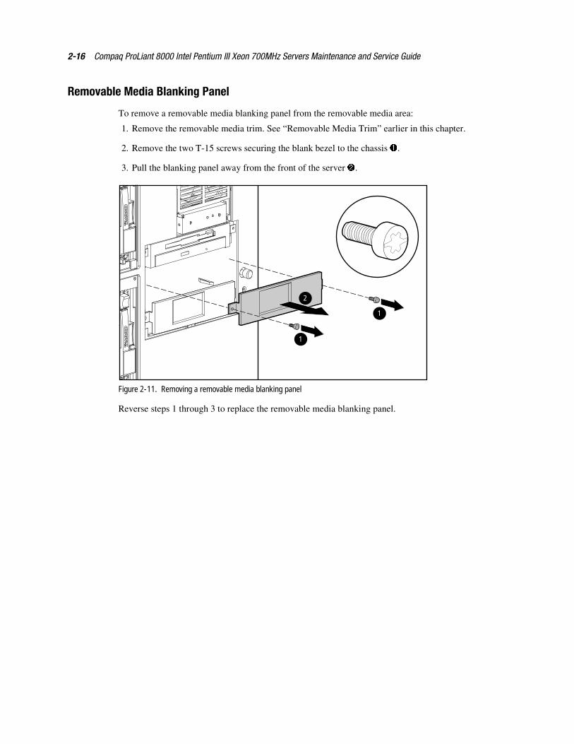
Removable Media Blanking Panel
To remove a removable media blanking panel from the removable media area:
1. Remove the removable media trim. See “Removable Media Trim” earlier in this chapter.
2. Remove the two T-15 screws securing the blank bezel to the chassis �.
3. Pull the blanking panel away from the front of the server �.
1
1
2
Figure 2-11. Removing a removable media blanking panel
Reverse steps 1 through 3 to replace the removable media blanking panel.
Removal and Replacement Procedures 2-17
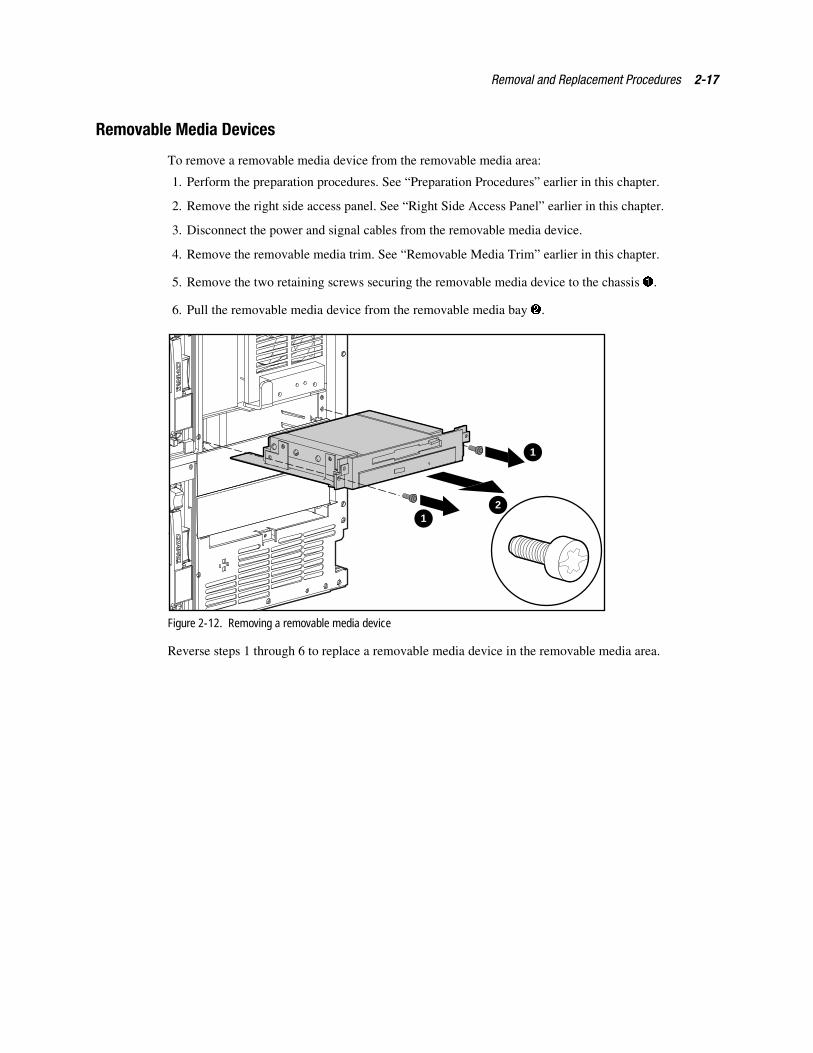
Removable Media Devices
To remove a removable media device from the removable media area:
1. Perform the preparation procedures. See “Preparation Procedures” earlier in this chapter.
2. Remove the right side access panel. See “Right Side Access Panel” earlier in this chapter.
3. Disconnect the power and signal cables from the removable media device.
4. Remove the removable media trim. See “Removable Media Trim” earlier in this chapter.
5. Remove the two retaining screws securing the removable media device to the chassis �.
6. Pull the removable media device from the removable media bay �.
1
12
Figure 2-12. Removing a removable media device
Reverse steps 1 through 6 to replace a removable media device in the removable media area.
2-18 Compaq ProLiant 8000 Intel Pentium III Xeon 700MHz Servers Maintenance and Service Guide
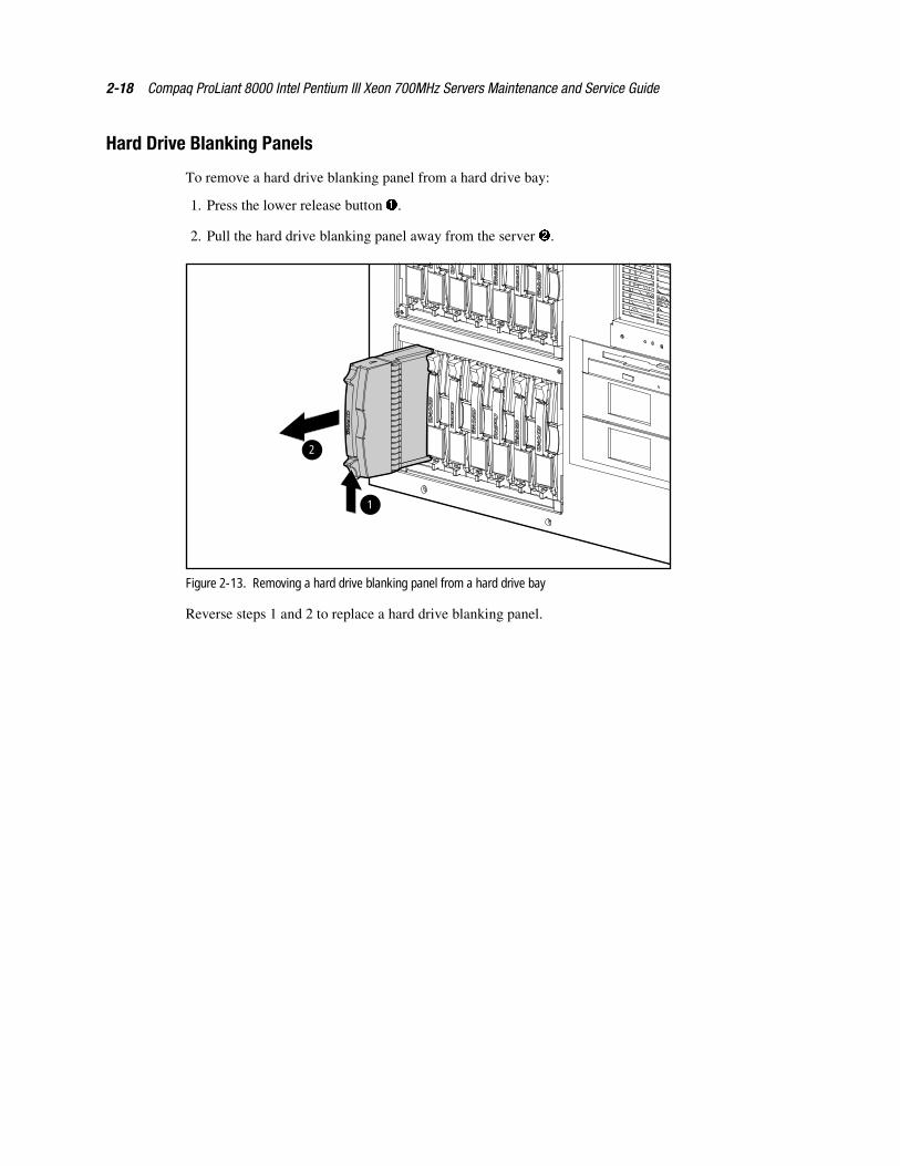
Hard Drive Blanking Panels
To remove a hard drive blanking panel from a hard drive bay:
1. Press the lower release button �.
2. Pull the hard drive blanking panel away from the server �.
2
1
Figure 2-13. Removing a hard drive blanking panel from a hard drive bay
Reverse steps 1 and 2 to replace a hard drive blanking panel.
Removal and Replacement Procedures 2-19
Hot-Plug Drive Replacement Guidelines
You should be able to hot-plug a drive during normal activity. Be aware, however, thathot-plugging a disk drive will affect system performance and fault tolerance.
NOTE: Depending upon your configuration, a drive failure and the subsequent rebuild process will causestorage subsystem performance degradation. For example, the replacement of a single drive on an arraywith 50 logical drives will have less impact than if the array has three logical drives.
When a disk drive is hot-plugged, although the system is functionally operational, the disksubsystem may no longer be fault tolerant.
CAUTION: Fault tolerance will be lost until the removed drive is replaced and the rebuildoperation is completed (this will take several hours, even if the system is not busy while therebuild is in progress). If another drive in the array incurs an error during the period when faulttolerance is unavailable, a fatal system error could result.. If another drive fails during thisperiod, the entire contents of the array will be lost.
IMPORTANT: Perform a disk drive replacement during low activity periods whenever possible. Inaddition, have a current valid backup available for the logical drives in the array of the drive beingreplaced, even if drive replacement is being made during server downtime.
Hot-Plug Drive Replacement Precautions
Be aware of the following Compaq guidelines for safe hot-plug replacement:
� Do not remove a degraded drive if any other member of the array is offline (the onlineLED is off). No other drive in the array can be hot-plugged without data loss, unlessRAID 0+1 is used as a fault tolerant form. In this case, drives are mirrored in pairs. Morethan one drive can fail and be replaced as long as the drive or drives they are mirroring areonline.
Refer to your Smart Array Controller user guide for information on fault toleranceoptions.
� Do not remove a degraded drive if any member of an array is missing (previouslyremoved and not yet replaced).
� Do not remove a degraded drive if any member of an array is being rebuilt, unless thedrive being rebuilt has been configured as an online spare. The online LED for the drivebeing rebuilt will flash, indicating that a replaced drive is being rebuilt from data stored onthe other drives.
NOTE: An online spare will not activate and start rebuilding after a predictive failure alert because thedegraded drive is still online. The online spare activates only after a drive in the array has failed.
� Do not replace multiple degraded drives at the same time (for example, when the system isoff), or the fault tolerance may be compromised. When a drive is replaced, the controlleruses data from the other drives in the array to reconstruct data on the replacement drive. Ifmore than one drive is removed, a complete data set is not available to reconstruct data onthe replacement drive or drives, and permanent data loss could occur.
2-20 Compaq ProLiant 8000 Intel Pentium III Xeon 700MHz Servers Maintenance and Service Guide
CAUTION: Do not turn off an attached disk drive enclosure when the server containing theSmart Array Controller is powered on. Also, do not turn on the server before turning on the diskenclosure. If these ordering rules are not followed, the Smart Array Controller may mark thedrives in this enclosure as “failed,” which could result in permanent data loss.
NOTE: For more information on hard drive LED statuses, refer to Chapter 4.
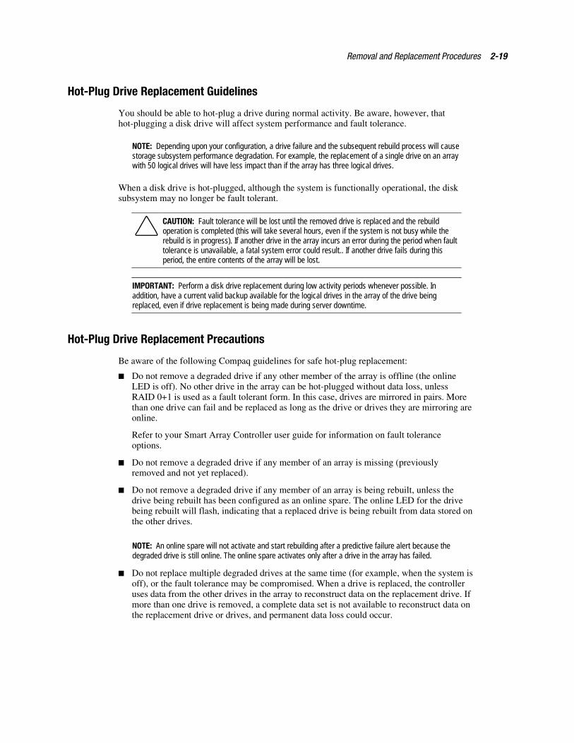
To remove a hot-plug SCSI hard drive:
CAUTION: Replace a hot-plug SCSI hard drive only when the drive LED is amber. Do notremove a hot-plug SCSI hard drive if the online LED is green.
1. Press the release button for the SCSI hard drive ejector lever �.
2. Pull the locking release lever � forward.
3. Pull the hard drive from the drive cage �.
1
2
3
Figure 2-14. Removing a hot-plug SCSI hard drive
Reverse steps 1 through 3 to replace a hot-plug SCSI hard drive.
Removal and Replacement Procedures 2-21
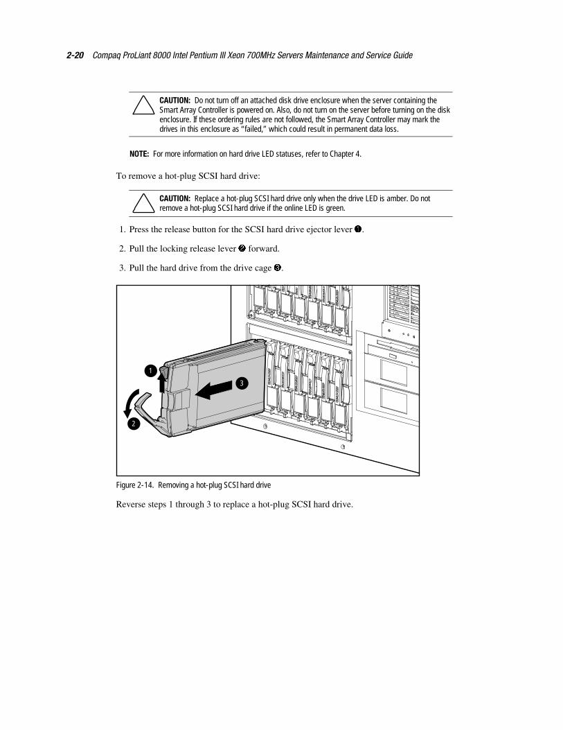
Drive Cage with Backplane BoardTo remove a drive cage with backplane board:
1. Perform the preparation procedures. See “Preparation Procedures” earlier in this chapter.
2. Remove the left side access panel. See “Left Side Access Panel” earlier in this chapter.
3. Disconnect the power and SCSI cables from the backplane board.
4. Remove all drives from the drive cage. See “Hot-Plug Drive Replacement Guidelines”earlier in this chapter.
CAUTION: Hard drives removed from the drive bays must be replaced into the same slots fromwhich they were removed to preserve data integrity.
5. Remove the two slotted T-15 screws from the front of the drive cage.
6. Pull out the drive cage assembly.
Figure 2-15. Removing the drive cage with backplane board
Reverse steps 1 through 6 to replace the drive cage with backplane board.
CAUTION: If an internal drive cage bay does not contain a drive cage, you must install ahot-plug drive cage blanking panel to ensure proper system cooling.
2-22 Compaq ProLiant 8000 Intel Pentium III Xeon 700MHz Servers Maintenance and Service Guide
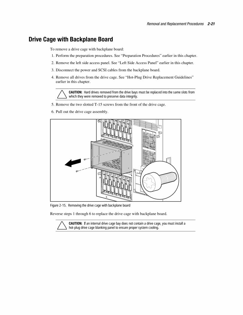
Power On/Standby SwitchTo remove the Power On/Standby switch:
1. Perform the preparation procedures. See “Preparation Procedures” earlier in this chapter.
2. Remove the top access panel. See “Top Access Panel” earlier in this chapter.
3. Disconnect the Power On/Standby switch connector from the I/O board location shown inFigure 2-16.
4. Remove the power LED from the plastic LED holder on the chassis.
Figure 2-16. Disconnecting the Power On/Standby switch connector from the I/O board
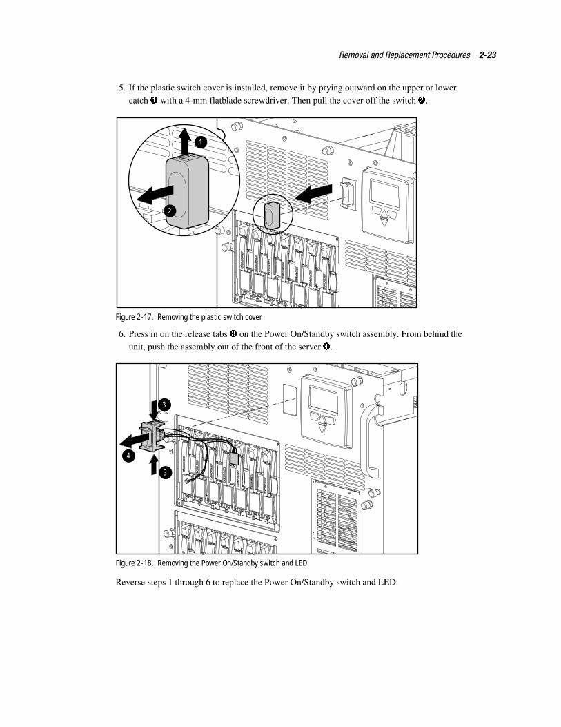
Removal and Replacement Procedures 2-23
5. If the plastic switch cover is installed, remove it by prying outward on the upper or lower
catch � with a 4-mm flatblade screwdriver. Then pull the cover off the switch �.
1
2
Figure 2-17. Removing the plastic switch cover
6. Press in on the release tabs � on the Power On/Standby switch assembly. From behind theunit, push the assembly out of the front of the server �.
3
4
3
Figure 2-18. Removing the Power On/Standby switch and LED
Reverse steps 1 through 6 to replace the Power On/Standby switch and LED.
2-24 Compaq ProLiant 8000 Intel Pentium III Xeon 700MHz Servers Maintenance and Service Guide
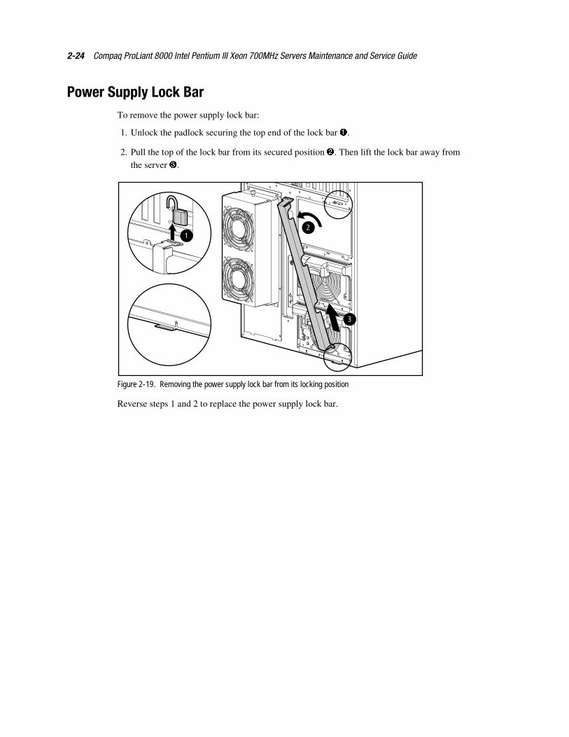
Power Supply Lock BarTo remove the power supply lock bar:
1. Unlock the padlock securing the top end of the lock bar �.
2. Pull the top of the lock bar from its secured position �. Then lift the lock bar away fromthe server �.
12
3
Figure 2-19. Removing the power supply lock bar from its locking position
Reverse steps 1 and 2 to replace the power supply lock bar.
Removal and Replacement Procedures 2-25
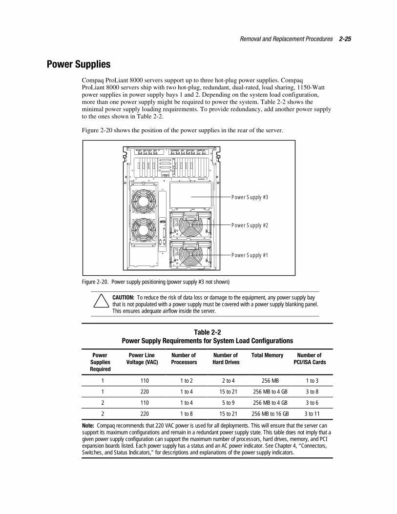
Power SuppliesCompaq ProLiant 8000 servers support up to three hot-plug power supplies. CompaqProLiant 8000 servers ship with two hot-plug, redundant, dual-rated, load sharing, 1150-Wattpower supplies in power supply bays 1 and 2. Depending on the system load configuration,more than one power supply might be required to power the system. Table 2-2 shows theminimal power supply loading requirements. To provide redundancy, add another power supplyto the ones shown in Table 2-2.
Figure 2-20 shows the position of the power supplies in the rear of the server.
Power Supply #3
Power Supply #2
Power Supply #1
Figure 2-20. Power supply positioning (power supply #3 not shown)
CAUTION: To reduce the risk of data loss or damage to the equipment, any power supply baythat is not populated with a power supply must be covered with a power supply blanking panel.This ensures adequate airflow inside the server.
Table 2-2Power Supply Requirements for System Load Configurations
PowerSuppliesRequired
Power LineVoltage (VAC)
Number ofProcessors
Number ofHard Drives
Total Memory Number ofPCI/ISA Cards
1 110 1 to 2 2 to 4 256 MB 1 to 3
1 220 1 to 4 15 to 21 256 MB to 4 GB 3 to 8
2 110 1 to 4 5 to 9 256 MB to 4 GB 3 to 6
2 220 1 to 8 15 to 21 256 MB to 16 GB 3 to 11
Note: Compaq recommends that 220 VAC power is used for all deployments. This will ensure that the server cansupport its maximum configurations and remain in a redundant power supply state. This table does not imply that agiven power supply configuration can support the maximum number of processors, hard drives, memory, and PCIexpansion boards listed. Each power supply has a status and an AC power indicator. See Chapter 4, “Connectors,Switches, and Status Indicators,” for descriptions and explanations of the power supply indicators.
2-26 Compaq ProLiant 8000 Intel Pentium III Xeon 700MHz Servers Maintenance and Service Guide
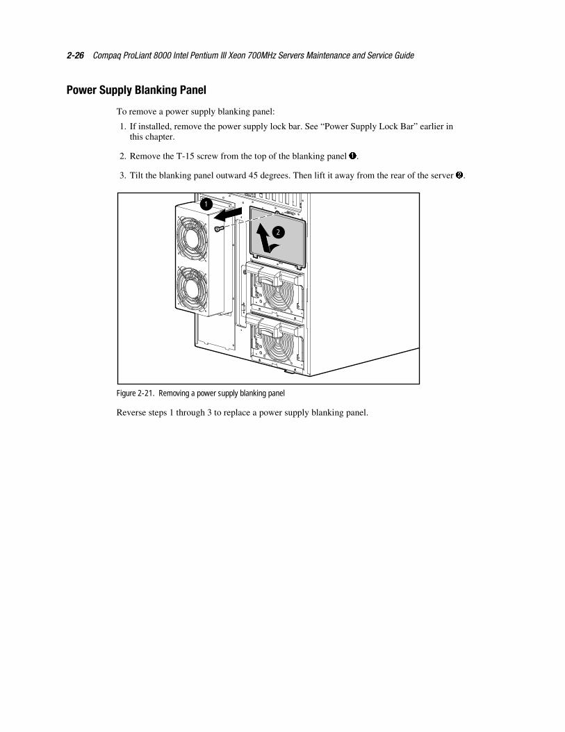
Power Supply Blanking Panel
To remove a power supply blanking panel:
1. If installed, remove the power supply lock bar. See “Power Supply Lock Bar” earlier inthis chapter.
2. Remove the T-15 screw from the top of the blanking panel �.
3. Tilt the blanking panel outward 45 degrees. Then lift it away from the rear of the server �.
2
1
Figure 2-21. Removing a power supply blanking panel
Reverse steps 1 through 3 to replace a power supply blanking panel.
Removal and Replacement Procedures 2-27
Hot-Plug Power Supplies
To remove a hot-plug power supply:
1. In a redundant power supply configuration, it is unnecessary to turn off the power for ahot-plug power supply replacement. For a non-redundant configuration, perform thepreparation procedures. See “Preparation Procedures” earlier in this chapter.
CAUTION: At least one power supply must be in place when changing out a hot-plug powersupply. If all three power supplies are to be changed out, perform a server shutdown.
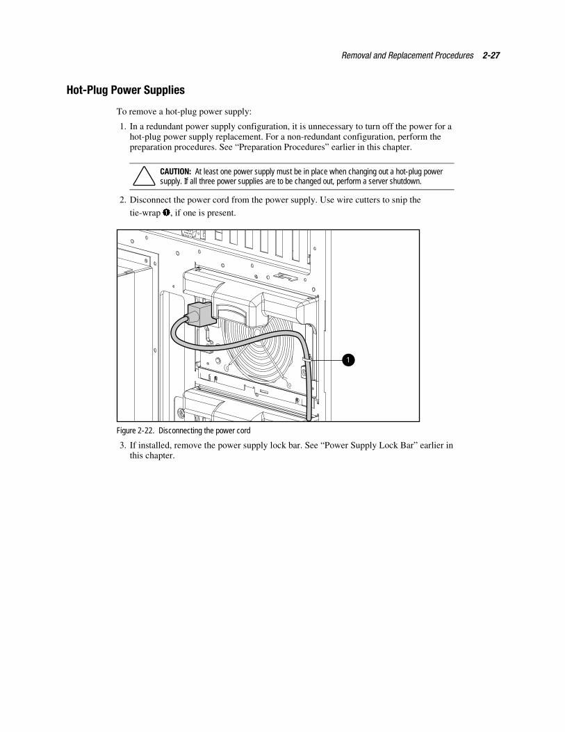
2. Disconnect the power cord from the power supply. Use wire cutters to snip the
tie-wrap �, if one is present.
1
Figure 2-22. Disconnecting the power cord
3. If installed, remove the power supply lock bar. See “Power Supply Lock Bar” earlier inthis chapter.
2-28 Compaq ProLiant 8000 Intel Pentium III Xeon 700MHz Servers Maintenance and Service Guide
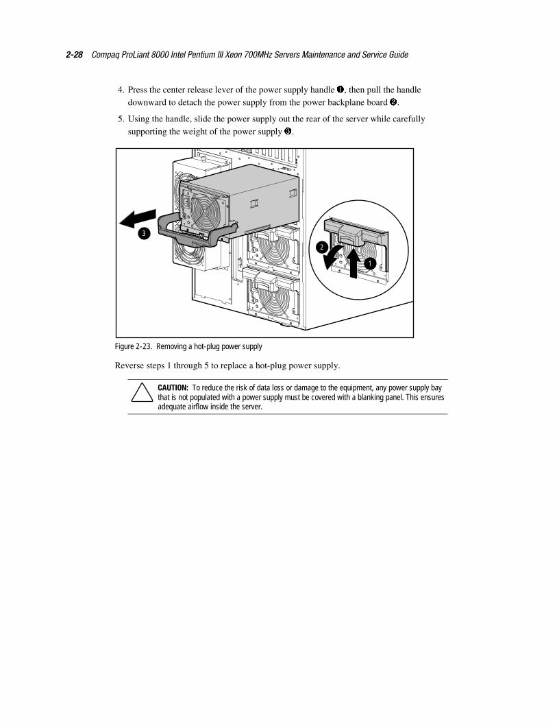
4. Press the center release lever of the power supply handle �, then pull the handledownward to detach the power supply from the power backplane board �.
5. Using the handle, slide the power supply out the rear of the server while carefully
supporting the weight of the power supply �.
2
1
3
Figure 2-23. Removing a hot-plug power supply
Reverse steps 1 through 5 to replace a hot-plug power supply.
CAUTION: To reduce the risk of data loss or damage to the equipment, any power supply baythat is not populated with a power supply must be covered with a blanking panel. This ensuresadequate airflow inside the server.
Removal and Replacement Procedures 2-29
Power Backplane BoardTo remove the power backplane board:
1. Perform the preparation procedures. See “Preparation Procedures” earlier in this chapter.
2. Remove the left side access panel. See “Left Side Access Panel” earlier in this chapter.
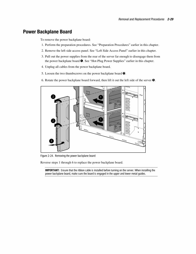
3. Pull out the power supplies from the rear of the server far enough to disengage them from
the power backplane board �. See “Hot-Plug Power Supplies” earlier in this chapter.
4. Unplug all cables from the power backplane board.
5. Loosen the two thumbscrews on the power backplane board �.
6. Rotate the power backplane board forward, then lift it out the left side of the server �.
1
1
2
3
2
Figure 2-24. Removing the power backplane board
Reverse steps 1 through 6 to replace the power backplane board.
IMPORTANT: Ensure that the ribbon cable is installed before turning on the server. When installing thepower backplane board, make sure the board is engaged in the upper and lower metal guides.
2-30 Compaq ProLiant 8000 Intel Pentium III Xeon 700MHz Servers Maintenance and Service Guide
FansProLiant 8000 servers ship with 10 cooling fans. There are four fan assemblies at the processorarea, two at the front and two at the rear of the server. An I/O fan assembly is located at the topof the server. All fans become active at startup. After reaching proper operating conditions, theredundant front and the redundant rear processor fans shut off. This is the normal fan sequencefor all ProLiant 8000 servers.
Hot-Plug Rear Processor Fan
To remove the hot-plug rear processor fan:
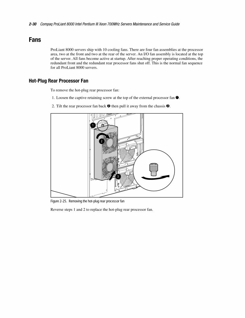
1. Loosen the captive retaining screw at the top of the external processor fan �.
2. Tilt the rear processor fan back � then pull it away from the chassis �.
2
3
1
Figure 2-25. Removing the hot-plug rear processor fan
Reverse steps 1 and 2 to replace the hot-plug rear processor fan.
Removal and Replacement Procedures 2-31
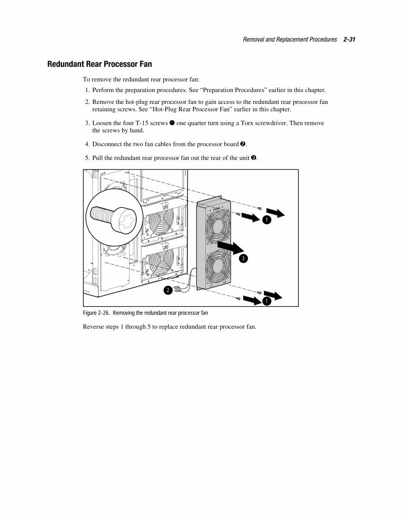
Redundant Rear Processor Fan
To remove the redundant rear processor fan:
1. Perform the preparation procedures. See “Preparation Procedures” earlier in this chapter.
2. Remove the hot-plug rear processor fan to gain access to the redundant rear processor fanretaining screws. See “Hot-Plug Rear Processor Fan” earlier in this chapter.
3. Loosen the four T-15 screws � one quarter turn using a Torx screwdriver. Then removethe screws by hand.
4. Disconnect the two fan cables from the processor board �.
5. Pull the redundant rear processor fan out the rear of the unit �.
1
1
2
3
Figure 2-26. Removing the redundant rear processor fan
Reverse steps 1 through 5 to replace redundant rear processor fan.
2-32 Compaq ProLiant 8000 Intel Pentium III Xeon 700MHz Servers Maintenance and Service Guide
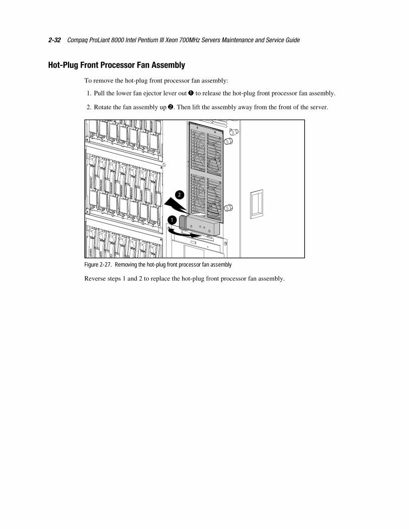
Hot-Plug Front Processor Fan Assembly
To remove the hot-plug front processor fan assembly:
1. Pull the lower fan ejector lever out � to release the hot-plug front processor fan assembly.
2. Rotate the fan assembly up �. Then lift the assembly away from the front of the server.
2
1
Figure 2-27. Removing the hot-plug front processor fan assembly
Reverse steps 1 and 2 to replace the hot-plug front processor fan assembly.
Removal and Replacement Procedures 2-33
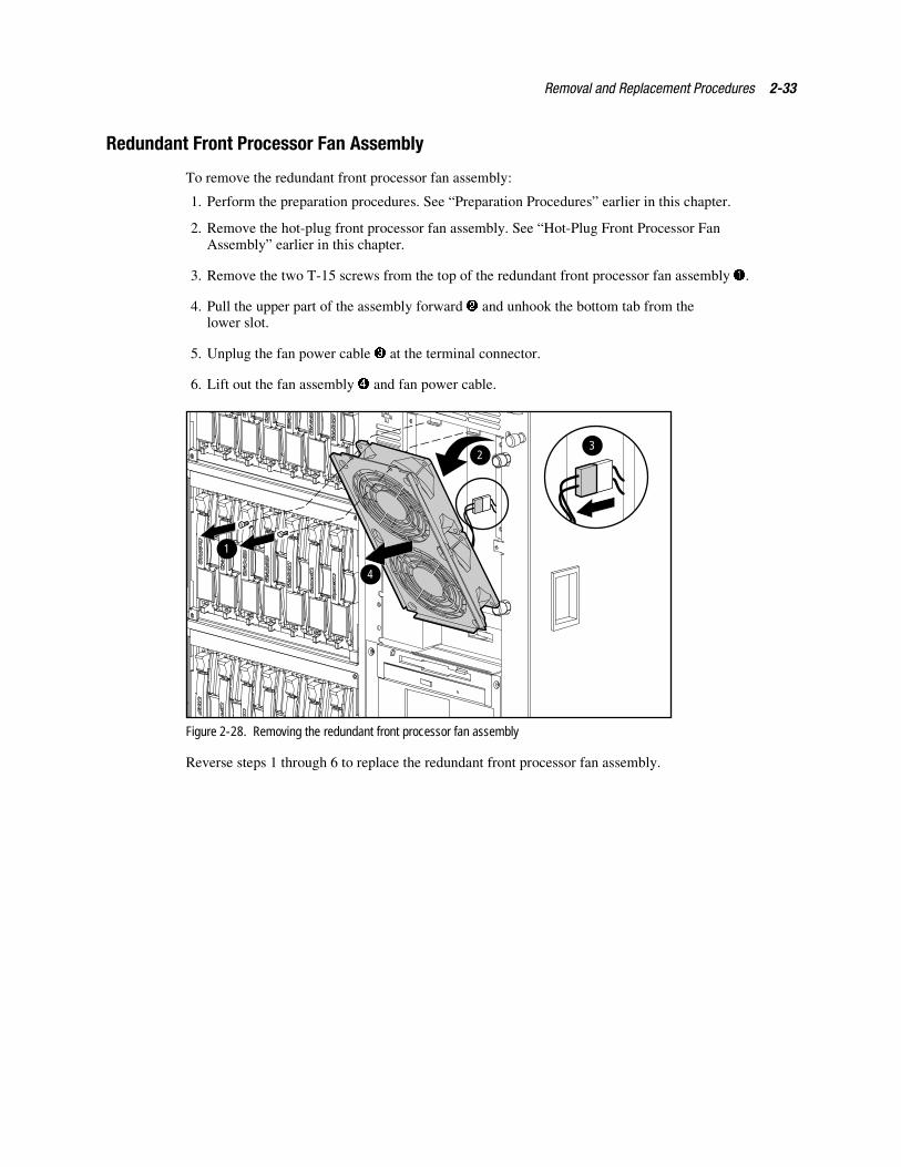
Redundant Front Processor Fan Assembly
To remove the redundant front processor fan assembly:
1. Perform the preparation procedures. See “Preparation Procedures” earlier in this chapter.
2. Remove the hot-plug front processor fan assembly. See “Hot-Plug Front Processor FanAssembly” earlier in this chapter.
3. Remove the two T-15 screws from the top of the redundant front processor fan assembly �.
4. Pull the upper part of the assembly forward � and unhook the bottom tab from thelower slot.
5. Unplug the fan power cable � at the terminal connector.
6. Lift out the fan assembly � and fan power cable.
1
2
4
3
Figure 2-28. Removing the redundant front processor fan assembly
Reverse steps 1 through 6 to replace the redundant front processor fan assembly.
2-34 Compaq ProLiant 8000 Intel Pentium III Xeon 700MHz Servers Maintenance and Service Guide
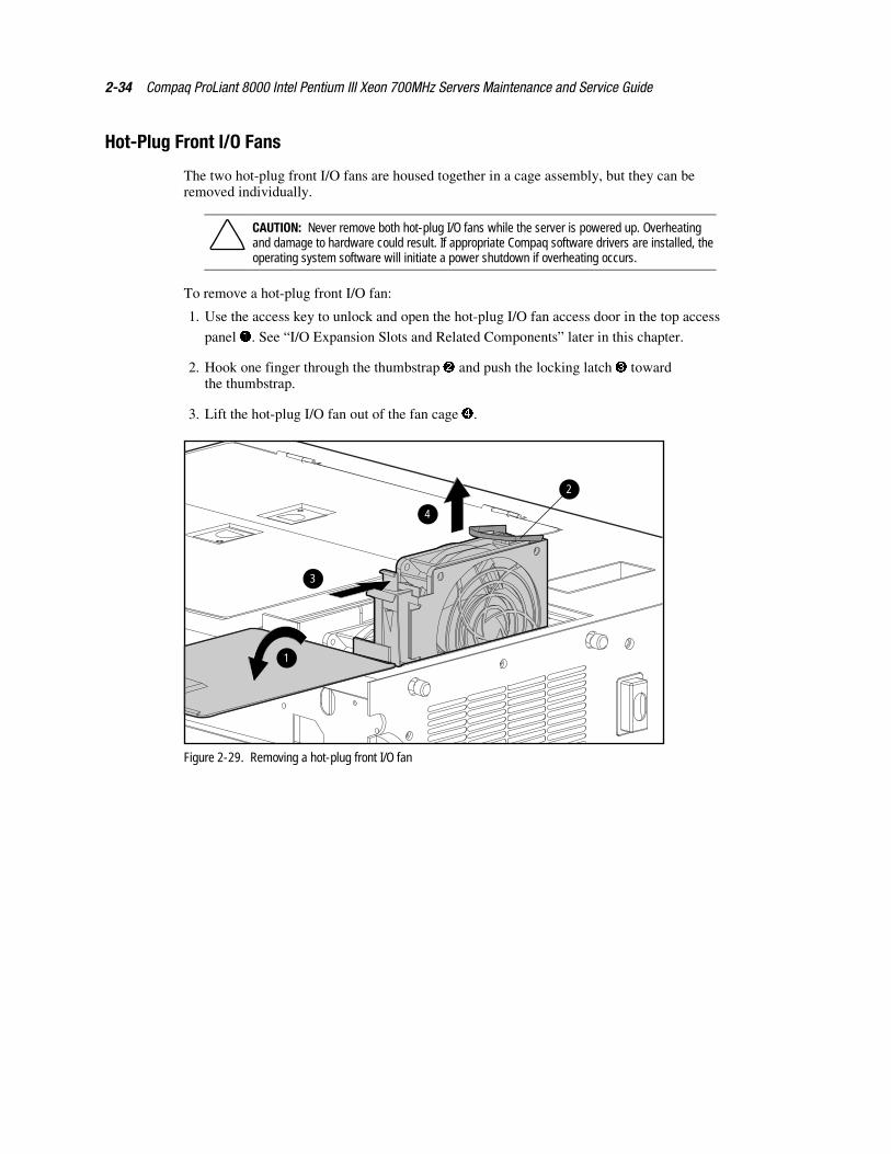
Hot-Plug Front I/O Fans
The two hot-plug front I/O fans are housed together in a cage assembly, but they can beremoved individually.
CAUTION: Never remove both hot-plug I/O fans while the server is powered up. Overheatingand damage to hardware could result. If appropriate Compaq software drivers are installed, theoperating system software will initiate a power shutdown if overheating occurs.
To remove a hot-plug front I/O fan:
1. Use the access key to unlock and open the hot-plug I/O fan access door in the top access
panel �. See “I/O Expansion Slots and Related Components” later in this chapter.
2. Hook one finger through the thumbstrap � and push the locking latch � towardthe thumbstrap.
3. Lift the hot-plug I/O fan out of the fan cage �.
1
4
3
2
Figure 2-29. Removing a hot-plug front I/O fan
Removal and Replacement Procedures 2-35
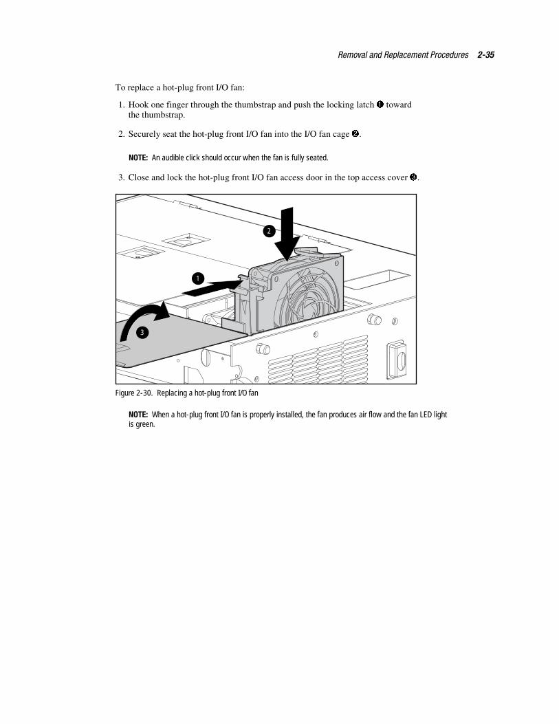
To replace a hot-plug front I/O fan:
1. Hook one finger through the thumbstrap and push the locking latch � towardthe thumbstrap.
2. Securely seat the hot-plug front I/O fan into the I/O fan cage �.
NOTE: An audible click should occur when the fan is fully seated.
3. Close and lock the hot-plug front I/O fan access door in the top access cover �.
1
3
2
Figure 2-30. Replacing a hot-plug front I/O fan
NOTE: When a hot-plug front I/O fan is properly installed, the fan produces air flow and the fan LED lightis green.
2-36 Compaq ProLiant 8000 Intel Pentium III Xeon 700MHz Servers Maintenance and Service Guide
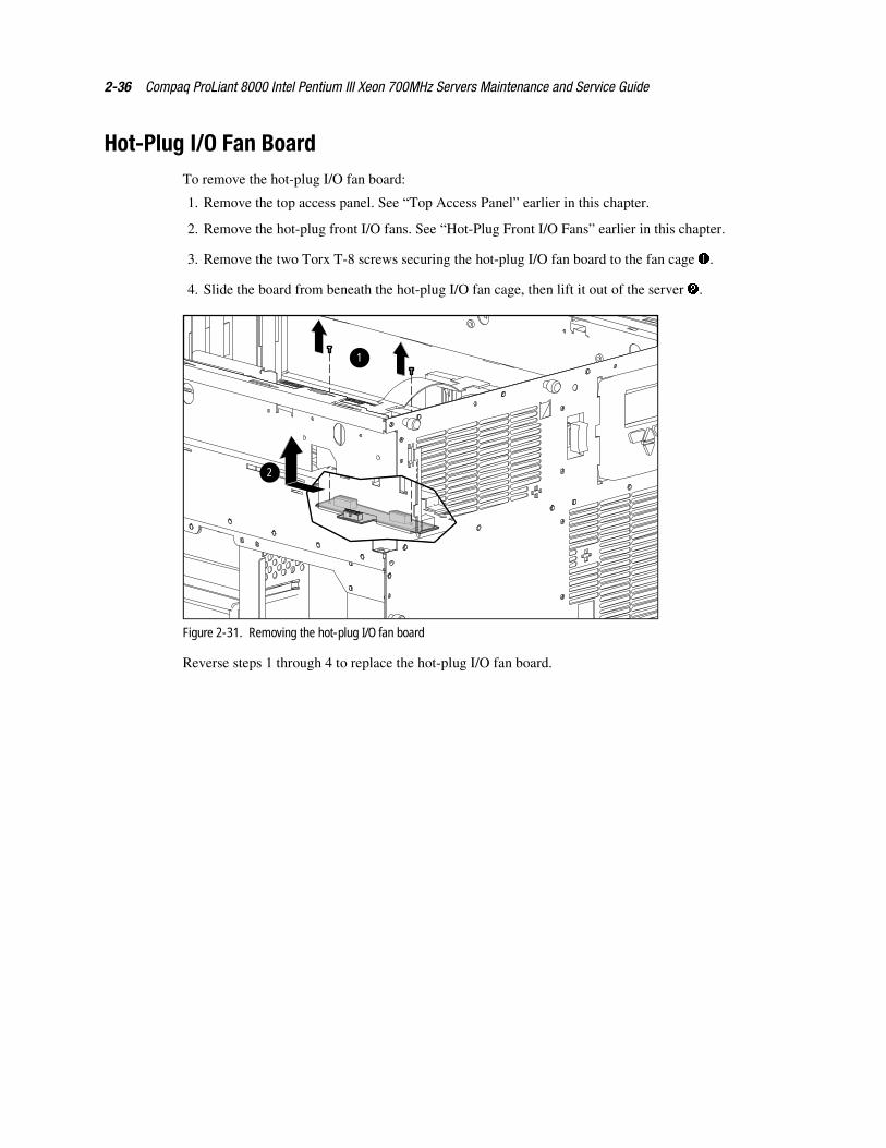
Hot-Plug I/O Fan BoardTo remove the hot-plug I/O fan board:
1. Remove the top access panel. See “Top Access Panel” earlier in this chapter.
2. Remove the hot-plug front I/O fans. See “Hot-Plug Front I/O Fans” earlier in this chapter.
3. Remove the two Torx T-8 screws securing the hot-plug I/O fan board to the fan cage �.
4. Slide the board from beneath the hot-plug I/O fan cage, then lift it out of the server �.
1
2
Figure 2-31. Removing the hot-plug I/O fan board
Reverse steps 1 through 4 to replace the hot-plug I/O fan board.
Removal and Replacement Procedures 2-37
SDRAM MemoryCompaq ProLiant 8000 servers use industry-standard synchronous dynamic RAM (SDRAM)dual inline memory modules (DIMMs) with single-bit error correction and single/multiple-biterror detection down to a single DIMM. Memory is expandable to 16 GB (16 x 1-GB DIMMs)by using all 16 DIMM sockets, two DIMM sockets to a bank. Both DIMMs in a bank must bethe same size, type, and speed, and both DIMMs in a bank must be installed at the same time.
Compaq ProLiant 8000 servers support 128-MB, 256-MB, 512-MB, and 1-GB 100-MHzSDRAM DIMMs.
IMPORTANT: The Power-On Self-Test (POST) warns of non-supported DIMMs. Mixing of memory speedson a memory expansion board is allowed, but the memory expansion board will run at the slowestmemory speed installed.
Dual Inline Memory Modules
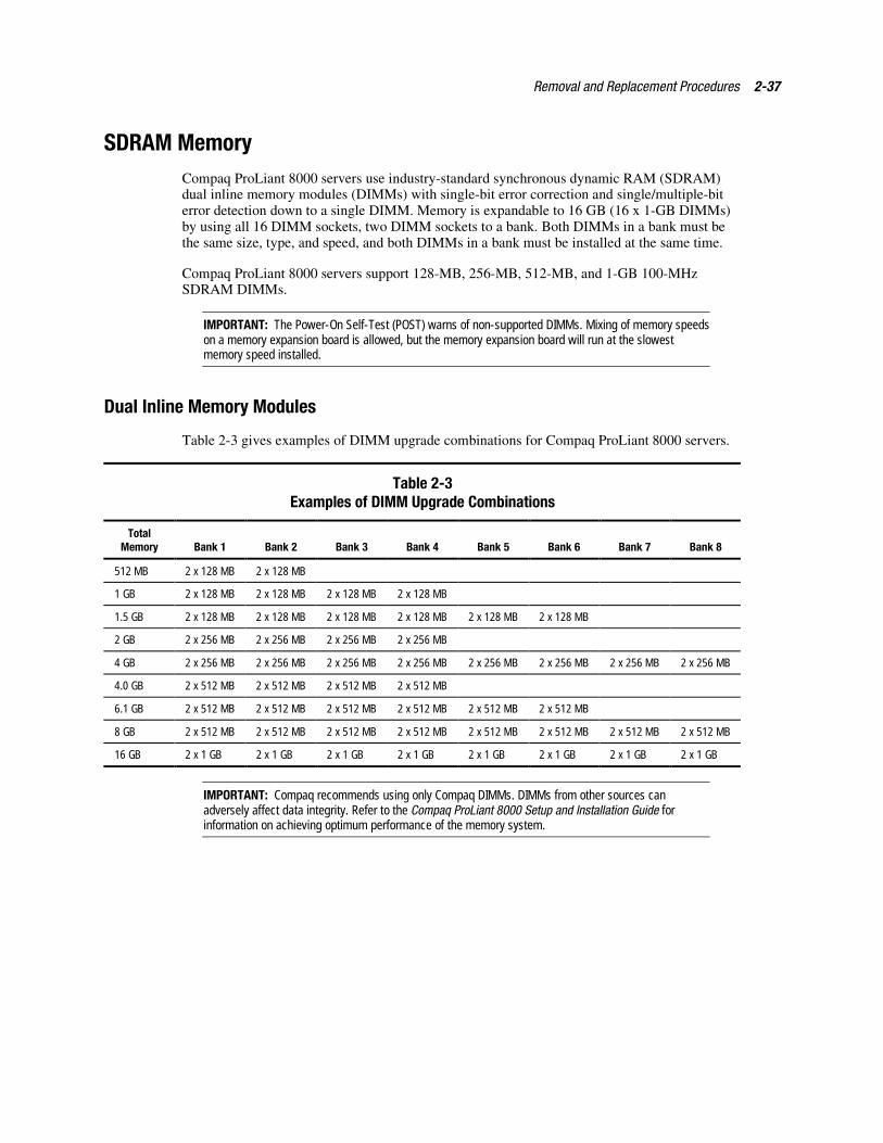
Table 2-3 gives examples of DIMM upgrade combinations for Compaq ProLiant 8000 servers.
Table 2-3Examples of DIMM Upgrade Combinations
TotalMemory Bank 1 Bank 2 Bank 3 Bank 4 Bank 5 Bank 6 Bank 7 Bank 8
512 MB 2 x 128 MB 2 x 128 MB
1 GB 2 x 128 MB 2 x 128 MB 2 x 128 MB 2 x 128 MB
1.5 GB 2 x 128 MB 2 x 128 MB 2 x 128 MB 2 x 128 MB 2 x 128 MB 2 x 128 MB
2 GB 2 x 256 MB 2 x 256 MB 2 x 256 MB 2 x 256 MB
4 GB 2 x 256 MB 2 x 256 MB 2 x 256 MB 2 x 256 MB 2 x 256 MB 2 x 256 MB 2 x 256 MB 2 x 256 MB
4.0 GB 2 x 512 MB 2 x 512 MB 2 x 512 MB 2 x 512 MB
6.1 GB 2 x 512 MB 2 x 512 MB 2 x 512 MB 2 x 512 MB 2 x 512 MB 2 x 512 MB
8 GB 2 x 512 MB 2 x 512 MB 2 x 512 MB 2 x 512 MB 2 x 512 MB 2 x 512 MB 2 x 512 MB 2 x 512 MB
16 GB 2 x 1 GB 2 x 1 GB 2 x 1 GB 2 x 1 GB 2 x 1 GB 2 x 1 GB 2 x 1 GB 2 x 1 GB
IMPORTANT: Compaq recommends using only Compaq DIMMs. DIMMs from other sources canadversely affect data integrity. Refer to the Compaq ProLiant 8000 Setup and Installation Guide forinformation on achieving optimum performance of the memory system.
2-38 Compaq ProLiant 8000 Intel Pentium III Xeon 700MHz Servers Maintenance and Service Guide
Memory Expansion Board
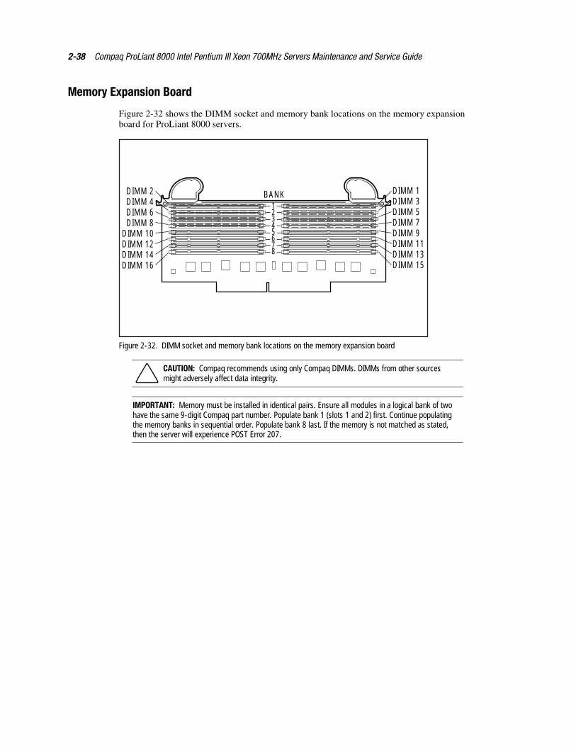
Figure 2-32 shows the DIMM socket and memory bank locations on the memory expansionboard for ProLiant 8000 servers.
DIMM 1DIMM 3DIMM 5DIMM 7DIMM 9DIMM 11DIMM 13DIMM 15
BANKDIMM 2DIMM 4DIMM 6DIMM 8
DIMM 10DIMM 12DIMM 14DIMM 16
12345678
Figure 2-32. DIMM socket and memory bank locations on the memory expansion board
CAUTION: Compaq recommends using only Compaq DIMMs. DIMMs from other sourcesmight adversely affect data integrity.
IMPORTANT: Memory must be installed in identical pairs. Ensure all modules in a logical bank of twohave the same 9-digit Compaq part number. Populate bank 1 (slots 1 and 2) first. Continue populatingthe memory banks in sequential order. Populate bank 8 last. If the memory is not matched as stated,then the server will experience POST Error 207.
Removal and Replacement Procedures 2-39
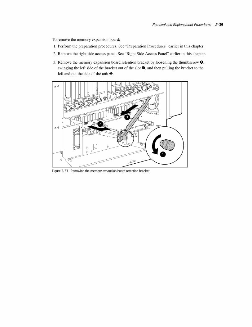
To remove the memory expansion board:
1. Perform the preparation procedures. See “Preparation Procedures” earlier in this chapter.
2. Remove the right side access panel. See “Right Side Access Panel” earlier in this chapter.
3. Remove the memory expansion board retention bracket by loosening the thumbscrew �,swinging the left side of the bracket out of the slot �, and then pulling the bracket to the
left and out the side of the unit �.
2
3
1
Figure 2-33. Removing the memory expansion board retention bracket
2-40 Compaq ProLiant 8000 Intel Pentium III Xeon 700MHz Servers Maintenance and Service Guide
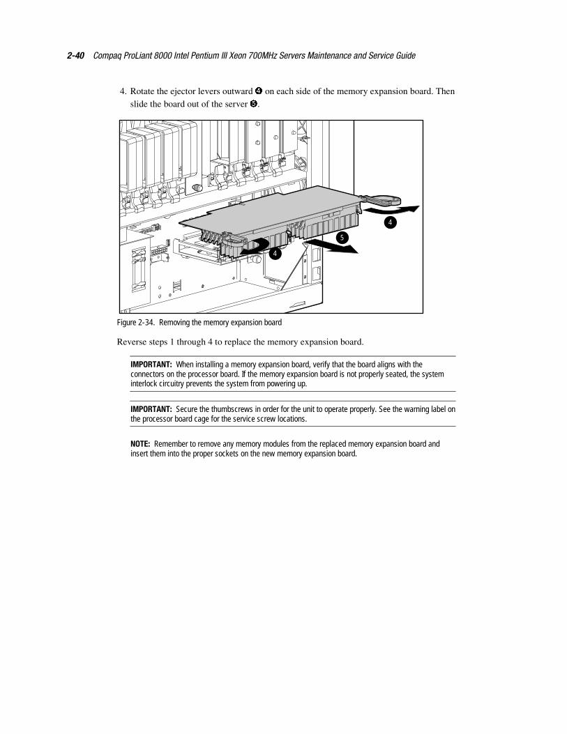
4. Rotate the ejector levers outward � on each side of the memory expansion board. Thenslide the board out of the server �.
4
4
5
Figure 2-34. Removing the memory expansion board
Reverse steps 1 through 4 to replace the memory expansion board.
IMPORTANT: When installing a memory expansion board, verify that the board aligns with theconnectors on the processor board. If the memory expansion board is not properly seated, the systeminterlock circuitry prevents the system from powering up.
IMPORTANT: Secure the thumbscrews in order for the unit to operate properly. See the warning label onthe processor board cage for the service screw locations.
NOTE: Remember to remove any memory modules from the replaced memory expansion board andinsert them into the proper sockets on the new memory expansion board.
Removal and Replacement Procedures 2-41
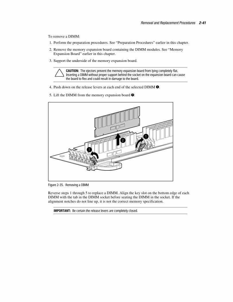
To remove a DIMM:
1. Perform the preparation procedures. See “Preparation Procedures” earlier in this chapter.
2. Remove the memory expansion board containing the DIMM modules. See “MemoryExpansion Board” earlier in this chapter.
3. Support the underside of the memory expansion board.
CAUTION: The ejectors prevent the memory expansion board from lying completely flat.Inserting a DIMM without proper support behind the socket on the expansion board can causethe board to flex and could result in damage to the board.
4. Push down on the release levers at each end of the selected DIMM �.
5. Lift the DIMM from the memory expansion board �.
1
12
Figure 2-35. Removing a DIMM
Reverse steps 1 through 5 to replace a DIMM. Align the key slot on the bottom edge of eachDIMM with the tab in the DIMM socket before seating the DIMM in the socket. If thealignment notches do not line up, it is not the correct memory specification.
IMPORTANT: Be certain the release levers are completely closed.
2-42 Compaq ProLiant 8000 Intel Pentium III Xeon 700MHz Servers Maintenance and Service Guide
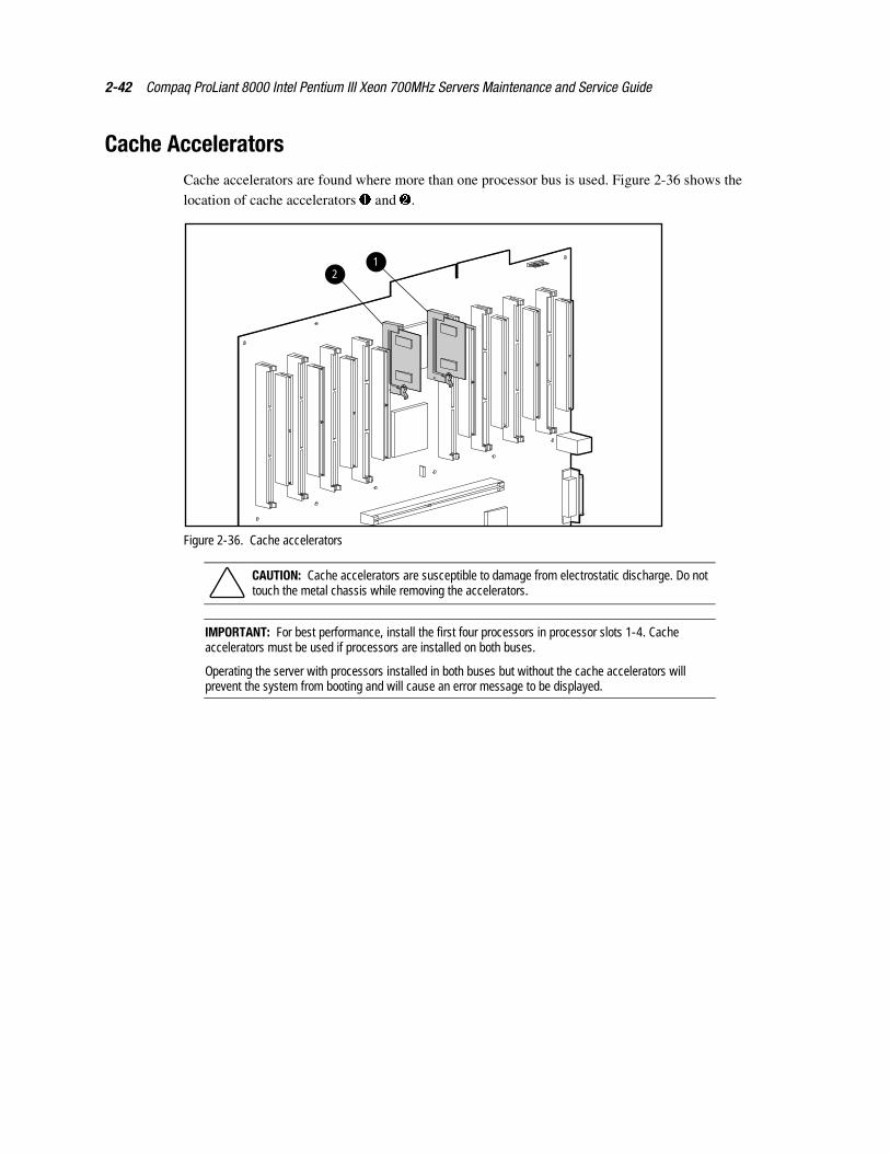
Cache AcceleratorsCache accelerators are found where more than one processor bus is used. Figure 2-36 shows thelocation of cache accelerators � and �.
21
Figure 2-36. Cache accelerators
CAUTION: Cache accelerators are susceptible to damage from electrostatic discharge. Do nottouch the metal chassis while removing the accelerators.
IMPORTANT: For best performance, install the first four processors in processor slots 1-4. Cacheaccelerators must be used if processors are installed on both buses.
Operating the server with processors installed in both buses but without the cache accelerators willprevent the system from booting and will cause an error message to be displayed.
Removal and Replacement Procedures 2-43
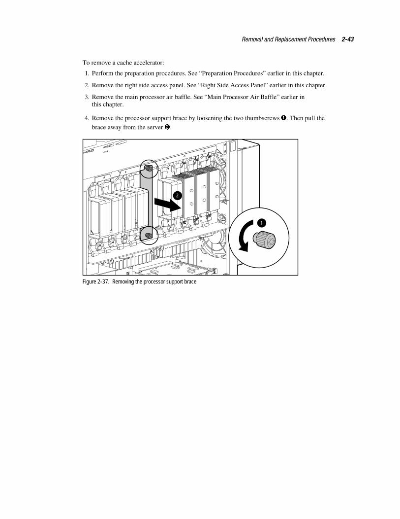
To remove a cache accelerator:
1. Perform the preparation procedures. See “Preparation Procedures” earlier in this chapter.
2. Remove the right side access panel. See “Right Side Access Panel” earlier in this chapter.
3. Remove the main processor air baffle. See “Main Processor Air Baffle” earlier inthis chapter.
4. Remove the processor support brace by loosening the two thumbscrews �. Then pull the
brace away from the server �.
1
2
Figure 2-37. Removing the processor support brace
2-44 Compaq ProLiant 8000 Intel Pentium III Xeon 700MHz Servers Maintenance and Service Guide
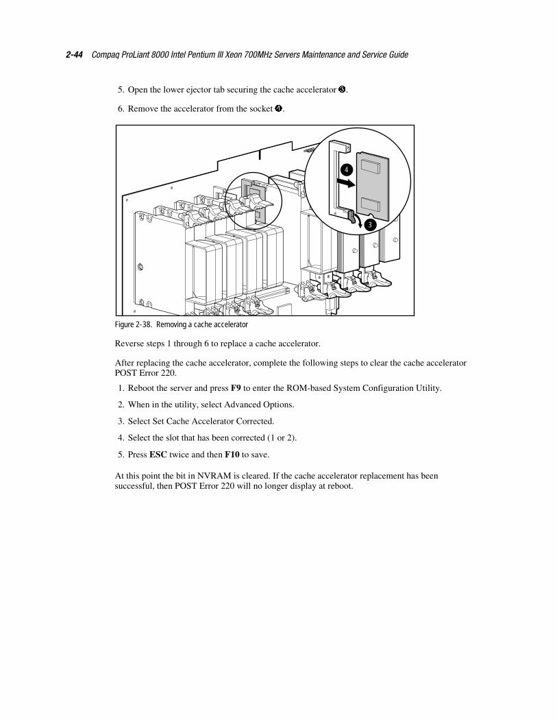
5. Open the lower ejector tab securing the cache accelerator �.
6. Remove the accelerator from the socket �.
3
4
Figure 2-38. Removing a cache accelerator
Reverse steps 1 through 6 to replace a cache accelerator.
After replacing the cache accelerator, complete the following steps to clear the cache acceleratorPOST Error 220.
1. Reboot the server and press F9 to enter the ROM-based System Configuration Utility.
2. When in the utility, select Advanced Options.
3. Select Set Cache Accelerator Corrected.
4. Select the slot that has been corrected (1 or 2).
5. Press ESC twice and then F10 to save.
At this point the bit in NVRAM is cleared. If the cache accelerator replacement has beensuccessful, then POST Error 220 will no longer display at reboot.
Removal and Replacement Procedures 2-45
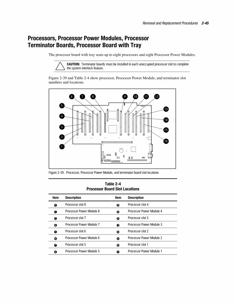
Processors, Processor Power Modules, ProcessorTerminator Boards, Processor Board with Tray
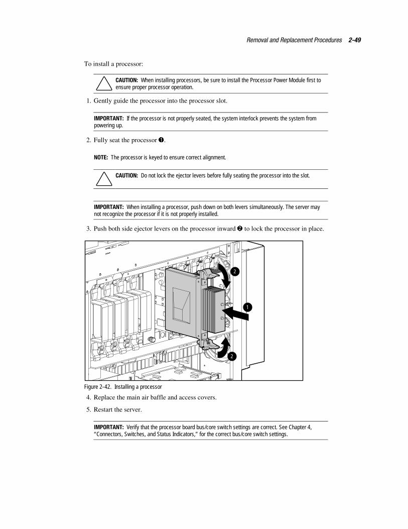
The processor board with tray seats up to eight processors and eight Processor Power Modules.
CAUTION: Terminator boards must be installed in each unoccupied processor slot to completethe system interlock feature.
Figure 2-39 and Table 2-4 show processor, Processor Power Module, and terminator slotnumbers and locations.
1
2
3
4
5
6 7 8 9 10 11 12
13
14
15
16
Figure 2-39. Processor, Processor Power Module, and terminator board slot locations
Table 2-4Processor Board Slot Locations
Item Description Item Description
� Processor slot 8 � Processor slot 4
� Processor Power Module 8 � Processor Power Module 4
� Processor slot 7 � Processor slot 3
� Processor Power Module 7 � Processor Power Module 3
Processor slot 6 Processor slot 2
� Processor Power Module 6 � Processor Power Module 2
Processor slot 5 � Processor slot 1
� Processor Power Module 5 � Processor Power Module 1
2-46 Compaq ProLiant 8000 Intel Pentium III Xeon 700MHz Servers Maintenance and Service Guide
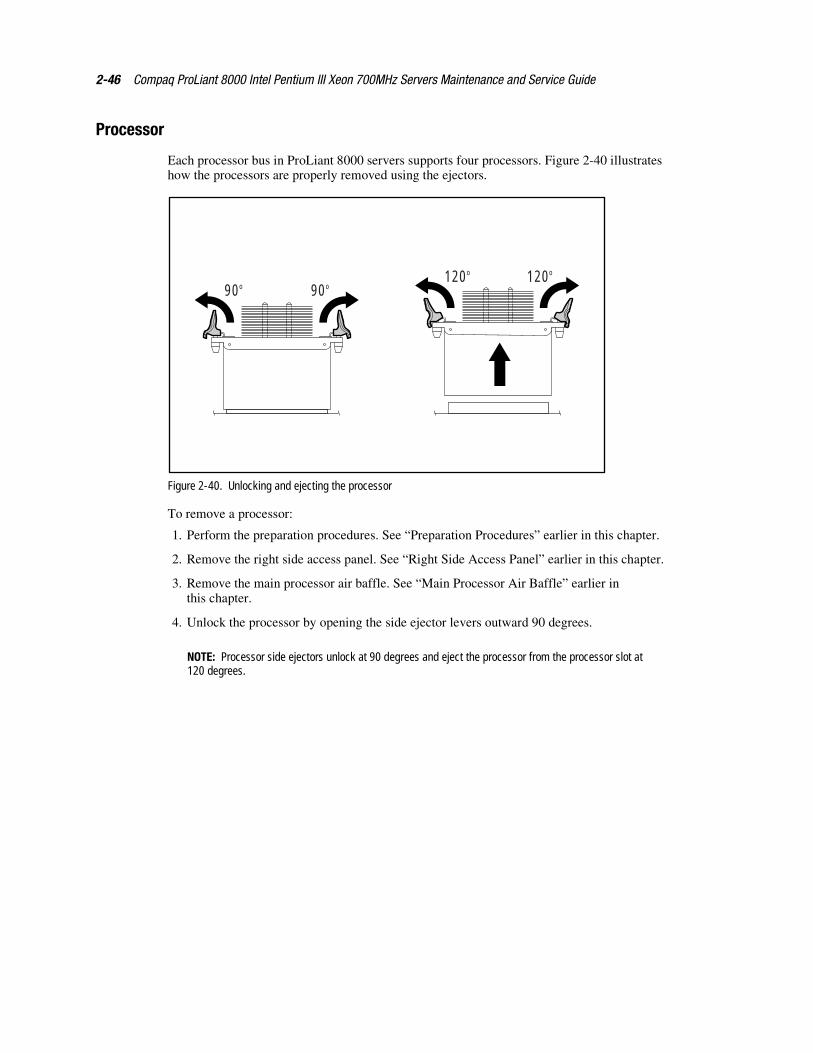
Processor
Each processor bus in ProLiant 8000 servers supports four processors. Figure 2-40 illustrateshow the processors are properly removed using the ejectors.
90o 90o120o 120o
Figure 2-40. Unlocking and ejecting the processor
To remove a processor:
1. Perform the preparation procedures. See “Preparation Procedures” earlier in this chapter.
2. Remove the right side access panel. See “Right Side Access Panel” earlier in this chapter.
3. Remove the main processor air baffle. See “Main Processor Air Baffle” earlier inthis chapter.
4. Unlock the processor by opening the side ejector levers outward 90 degrees.
NOTE: Processor side ejectors unlock at 90 degrees and eject the processor from the processor slot at120 degrees.
Removal and Replacement Procedures 2-47
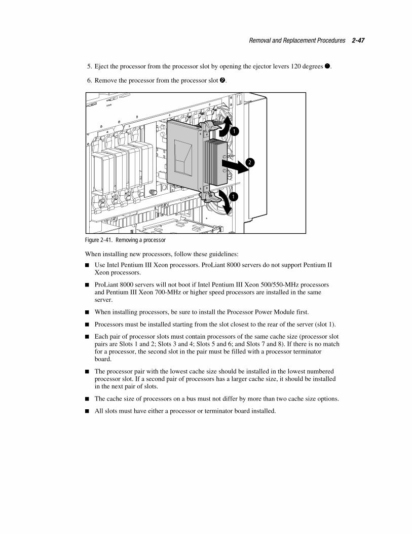
5. Eject the processor from the processor slot by opening the ejector levers 120 degrees �.
6. Remove the processor from the processor slot �.
2
1
1
Figure 2-41. Removing a processor
When installing new processors, follow these guidelines:
� Use Intel Pentium III Xeon processors. ProLiant 8000 servers do not support Pentium IIXeon processors.
� ProLiant 8000 servers will not boot if Intel Pentium III Xeon 500/550-MHz processorsand Pentium III Xeon 700-MHz or higher speed processors are installed in the sameserver.
� When installing processors, be sure to install the Processor Power Module first.
� Processors must be installed starting from the slot closest to the rear of the server (slot 1).
� Each pair of processor slots must contain processors of the same cache size (processor slotpairs are Slots 1 and 2; Slots 3 and 4; Slots 5 and 6; and Slots 7 and 8). If there is no matchfor a processor, the second slot in the pair must be filled with a processor terminatorboard.
� The processor pair with the lowest cache size should be installed in the lowest numberedprocessor slot. If a second pair of processors has a larger cache size, it should be installedin the next pair of slots.
� The cache size of processors on a bus must not differ by more than two cache size options.
� All slots must have either a processor or terminator board installed.
2-48 Compaq ProLiant 8000 Intel Pentium III Xeon 700MHz Servers Maintenance and Service Guide
Table 2-5 shows examples of processors installed using these guidelines.
Table 2-5Examples of Processor Mixing by Cache Size
Example Processors 1 and 2 Processors 3 and 4 Processors 5 and 6 Processors 7 and 8
1 1 MB 1 MB 1 MB 2 MB
1 MB 1 MB Terminator Board 2 MB
2 1 MB 2 MB 2 MB Terminator Board
1 MB 2 MB Terminator Board Terminator Board
With the bus/core ratio switches in the default position, the system ROM automatically detectsthe speed of processors installed on both processor buses. The processors automatically run atthe speed of the slowest processor installed in the server.
The default setting for the bus/core ratio switches has all switches in the Off position. Compaqrecommends that the bus/core ratio switches remain on the default setting to allow the systemROM to detect the correct speed automatically. If necessary, the bus/core ratio switches can bemanually set to force processor speed settings. See “Processor Board Bus/Core Frequency RatioSwitch Settings” in Chapter 4 for manual bus/core frequency switch settings.
CAUTION: If the bus/core ratio switches are set to a speed higher than the slowest processor,the server will not boot. Failure to properly set the bus/core ratio switches could damage theserver and void the warranty.
Removal and Replacement Procedures 2-49
To install a processor:
CAUTION: When installing processors, be sure to install the Processor Power Module first toensure proper processor operation.
1. Gently guide the processor into the processor slot.
IMPORTANT: If the processor is not properly seated, the system interlock prevents the system frompowering up.
2. Fully seat the processor �.
NOTE: The processor is keyed to ensure correct alignment.
CAUTION: Do not lock the ejector levers before fully seating the processor into the slot.
IMPORTANT: When installing a processor, push down on both levers simultaneously. The server maynot recognize the processor if it is not properly installed.
3. Push both side ejector levers on the processor inward � to lock the processor in place.
2
2
1
Figure 2-42. Installing a processor
4. Replace the main air baffle and access covers.
5. Restart the server.
IMPORTANT: Verify that the processor board bus/core switch settings are correct. See Chapter 4,“Connectors, Switches, and Status Indicators,” for the correct bus/core switch settings.
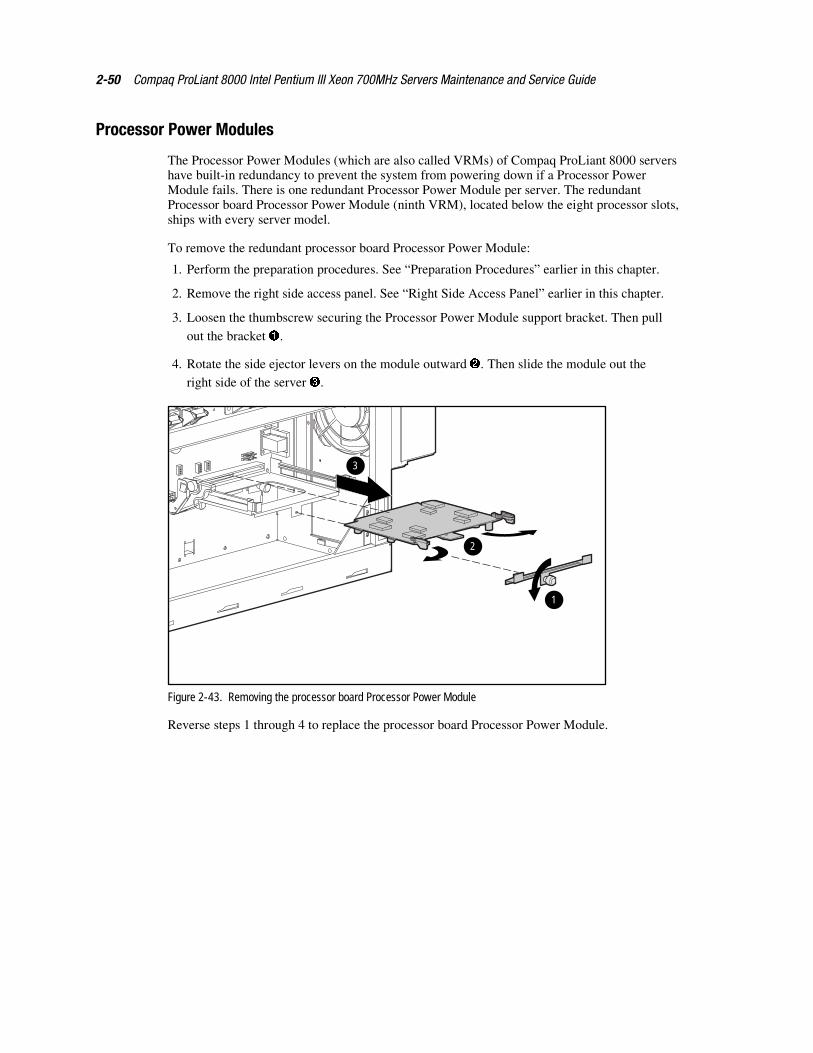
2-50 Compaq ProLiant 8000 Intel Pentium III Xeon 700MHz Servers Maintenance and Service Guide
Processor Power Modules
The Processor Power Modules (which are also called VRMs) of Compaq ProLiant 8000 servershave built-in redundancy to prevent the system from powering down if a Processor PowerModule fails. There is one redundant Processor Power Module per server. The redundantProcessor board Processor Power Module (ninth VRM), located below the eight processor slots,ships with every server model.
To remove the redundant processor board Processor Power Module:
1. Perform the preparation procedures. See “Preparation Procedures” earlier in this chapter.
2. Remove the right side access panel. See “Right Side Access Panel” earlier in this chapter.
3. Loosen the thumbscrew securing the Processor Power Module support bracket. Then pull
out the bracket �.
4. Rotate the side ejector levers on the module outward �. Then slide the module out theright side of the server �.
3
2
1
Figure 2-43. Removing the processor board Processor Power Module
Reverse steps 1 through 4 to replace the processor board Processor Power Module.

Removal and Replacement Procedures 2-51
To remove a Processor Power Module:
1. Perform the preparation procedures. See “Preparation Procedures” earlier in this chapter.
2. Remove the right side access panel. See “Right Side Access Panel” earlier in this chapter.
3. Remove the main processor air baffle. See “Main Processor Air Baffle” earlier inthis chapter.
4. Remove the processor associated with the Processor Power Module being replaced. Referto Figure 2-39 and the “
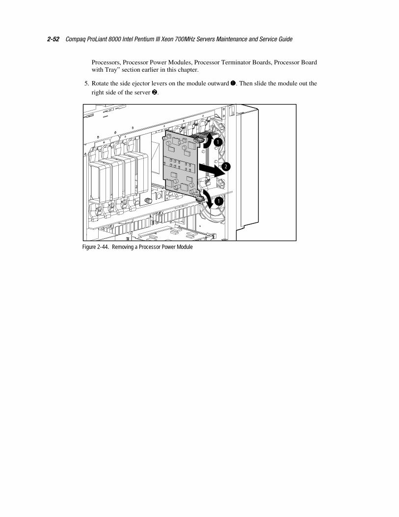
2-52 Compaq ProLiant 8000 Intel Pentium III Xeon 700MHz Servers Maintenance and Service Guide
Processors, Processor Power Modules, Processor Terminator Boards, Processor Boardwith Tray” section earlier in this chapter.
5. Rotate the side ejector levers on the module outward �. Then slide the module out theright side of the server �.
1
1
2
Figure 2-44. Removing a Processor Power Module
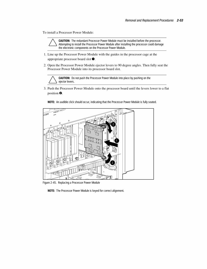
Removal and Replacement Procedures 2-53
To install a Processor Power Module:
CAUTION: The redundant Processor Power Module must be installed before the processor.Attempting to install the Processor Power Module after installing the processor could damagethe electronic components on the Processor Power Module.
1. Line up the Processor Power Module with the guides in the processor cage at the
appropriate processor board slot �.
2. Open the Processor Power Module ejector levers to 90 degree angles. Then fully seat theProcessor Power Module into its processor board slot.
CAUTION: Do not push the Processor Power Module into place by pushing on theejector levers.
3. Push the Processor Power Module onto the processor board until the levers lower to a flat
position �.
NOTE: An audible click should occur, indicating that the Processor Power Module is fully seated.
1
2
2
Figure 2-45. Replacing a Processor Power Module
NOTE: The Processor Power Module is keyed for correct alignment.
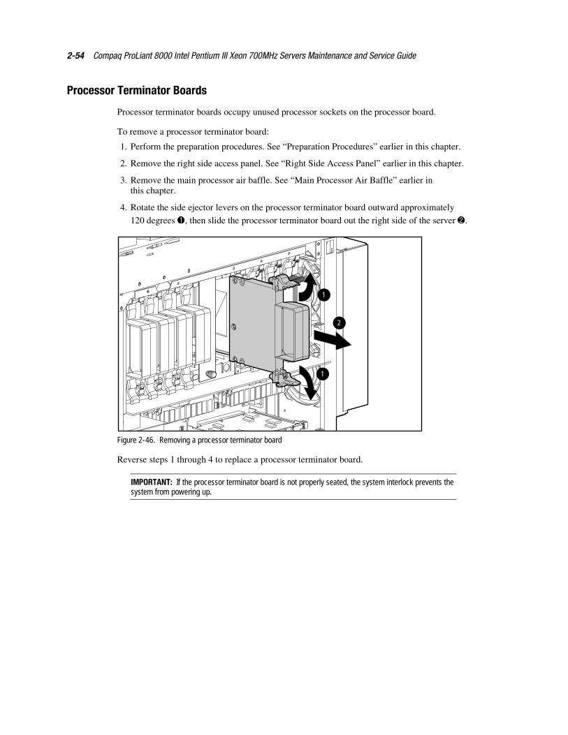
2-54 Compaq ProLiant 8000 Intel Pentium III Xeon 700MHz Servers Maintenance and Service Guide
Processor Terminator Boards
Processor terminator boards occupy unused processor sockets on the processor board.
To remove a processor terminator board:
1. Perform the preparation procedures. See “Preparation Procedures” earlier in this chapter.
2. Remove the right side access panel. See “Right Side Access Panel” earlier in this chapter.
3. Remove the main processor air baffle. See “Main Processor Air Baffle” earlier inthis chapter.
4. Rotate the side ejector levers on the processor terminator board outward approximately
120 degrees �, then slide the processor terminator board out the right side of the server �.
1
2
1
Figure 2-46. Removing a processor terminator board
Reverse steps 1 through 4 to replace a processor terminator board.
IMPORTANT: If the processor terminator board is not properly seated, the system interlock prevents thesystem from powering up.

Removal and Replacement Procedures 2-55
Lower Processor Support StructureTo remove the lower processor support structure:
1. Perform the preparation procedures. See “Preparation Procedures” earlier in this chapter.
2. Remove the right side access panel. See “Right Side Access Panel” earlier in this chapter.
3. Remove the front and rear air baffles. See “Front Air Baffle” and “Rear Air Baffle” earlierin this chapter.
4. Remove the main processor air baffle. See “Main Processor Air Baffle” earlier inthis chapter.
5. Remove all processors, Processor Power Modules, and terminator boards. See “
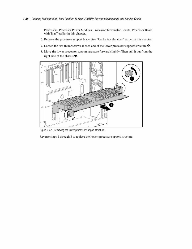
2-56 Compaq ProLiant 8000 Intel Pentium III Xeon 700MHz Servers Maintenance and Service Guide
Processors, Processor Power Modules, Processor Terminator Boards, Processor Boardwith Tray” earlier in this chapter.
6. Remove the processor support brace. See “Cache Accelerators” earlier in this chapter.
7. Loosen the two thumbscrews at each end of the lower processor support structure �.
8. Move the lower processor support structure forward slightly. Then pull it out from the
right side of the chassis �.
1
2
Figure 2-47. Removing the lower processor support structure
Reverse steps 1 through 8 to replace the lower processor support structure.
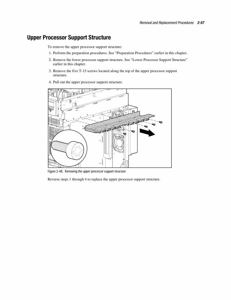
Removal and Replacement Procedures 2-57
Upper Processor Support StructureTo remove the upper processor support structure:
1. Perform the preparation procedures. See “Preparation Procedures” earlier in this chapter.
2. Remove the lower processor support structure. See “Lower Processor Support Structure”earlier in this chapter.
3. Remove the five T-15 screws located along the top of the upper processor supportstructure.
4. Pull out the upper processor support structure.
Figure 2-48. Removing the upper processor support structure
Reverse steps 1 through 4 to replace the upper processor support structure.
2-58 Compaq ProLiant 8000 Intel Pentium III Xeon 700MHz Servers Maintenance and Service Guide
Processor Board with Tray
To remove the processor board with tray:
1. Perform the preparation procedures. See “Preparation Procedures” earlier in this chapter.
2. Remove the top access panel. See “Top Access Panel” earlier in this chapter.
3. Remove the right side access panel. See “Right Side Access Panel” earlier in this chapter.
4. Remove the memory expansion board. See “Memory Expansion Board” earlier inthis chapter.
5. Remove the main processor air baffle. See “Main Processor Air Baffle” earlier inthis chapter.
6. Remove all Processor Power Modules except the Processor board Processor PowerModule (ninth VRM), processors, and terminator boards. See “
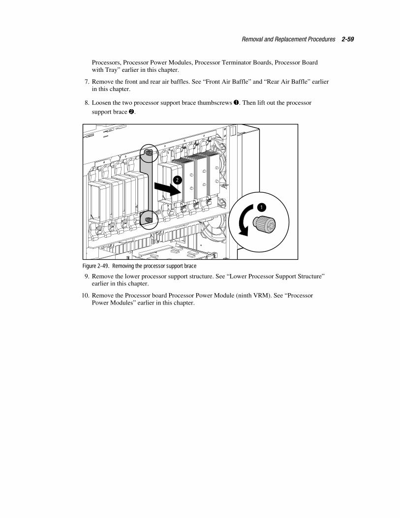
Removal and Replacement Procedures 2-59
Processors, Processor Power Modules, Processor Terminator Boards, Processor Boardwith Tray” earlier in this chapter.
7. Remove the front and rear air baffles. See “Front Air Baffle” and “Rear Air Baffle” earlierin this chapter.
8. Loosen the two processor support brace thumbscrews �. Then lift out the processor
support brace �.
1
2
Figure 2-49. Removing the processor support brace
9. Remove the lower processor support structure. See “Lower Processor Support Structure”earlier in this chapter.
10. Remove the Processor board Processor Power Module (ninth VRM). See “ProcessorPower Modules” earlier in this chapter.
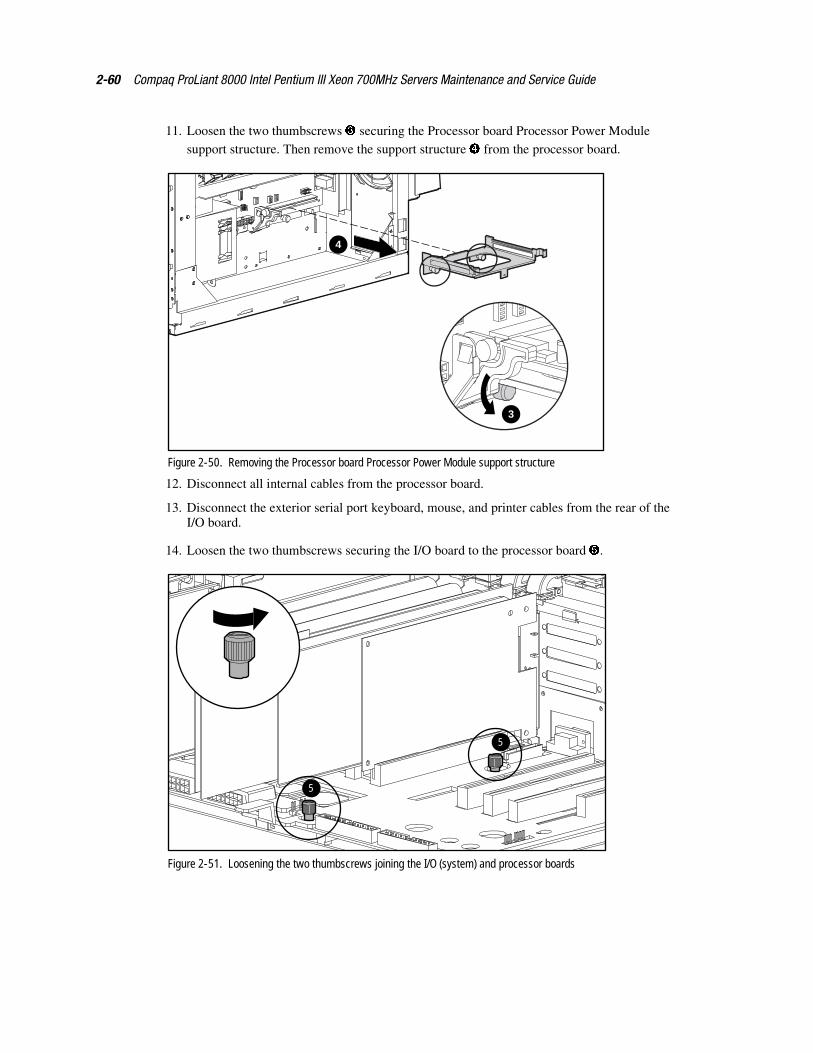
2-60 Compaq ProLiant 8000 Intel Pentium III Xeon 700MHz Servers Maintenance and Service Guide
11. Loosen the two thumbscrews � securing the Processor board Processor Power Modulesupport structure. Then remove the support structure � from the processor board.
3
4
Figure 2-50. Removing the Processor board Processor Power Module support structure
12. Disconnect all internal cables from the processor board.
13. Disconnect the exterior serial port keyboard, mouse, and printer cables from the rear of theI/O board.
14. Loosen the two thumbscrews securing the I/O board to the processor board �.
5
5
Figure 2-51. Loosening the two thumbscrews joining the I/O (system) and processor boards
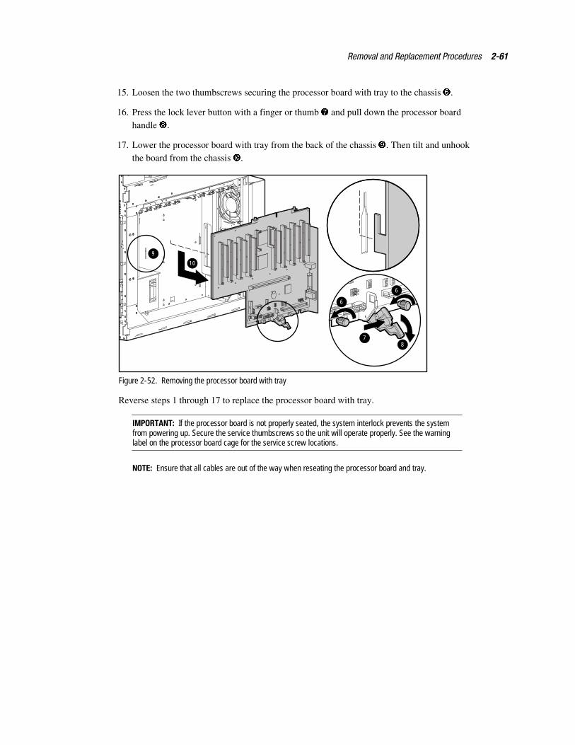
Removal and Replacement Procedures 2-61
15. Loosen the two thumbscrews securing the processor board with tray to the chassis �.
16. Press the lock lever button with a finger or thumb � and pull down the processor boardhandle �.
17. Lower the processor board with tray from the back of the chassis . Then tilt and unhookthe board from the chassis .
10
2
6
6
87
9
Figure 2-52. Removing the processor board with tray
Reverse steps 1 through 17 to replace the processor board with tray.
IMPORTANT: If the processor board is not properly seated, the system interlock prevents the systemfrom powering up. Secure the service thumbscrews so the unit will operate properly. See the warninglabel on the processor board cage for the service screw locations.
NOTE: Ensure that all cables are out of the way when reseating the processor board and tray.
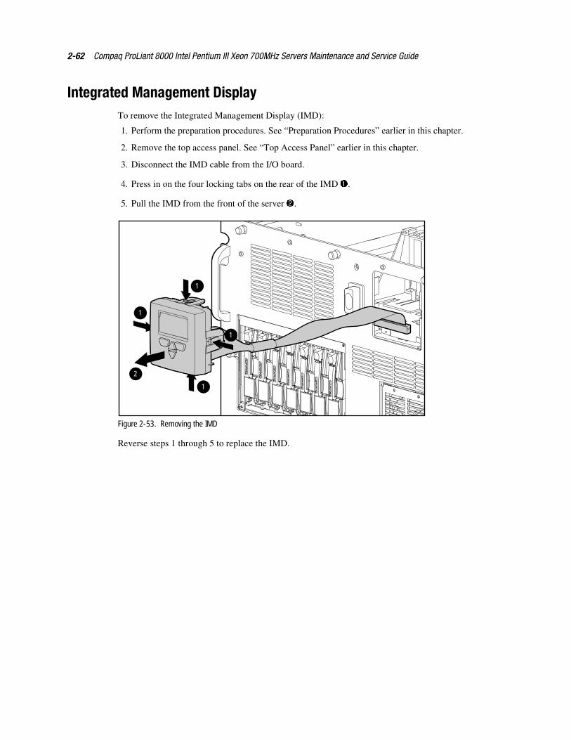
2-62 Compaq ProLiant 8000 Intel Pentium III Xeon 700MHz Servers Maintenance and Service Guide
Integrated Management DisplayTo remove the Integrated Management Display (IMD):
1. Perform the preparation procedures. See “Preparation Procedures” earlier in this chapter.
2. Remove the top access panel. See “Top Access Panel” earlier in this chapter.
3. Disconnect the IMD cable from the I/O board.
4. Press in on the four locking tabs on the rear of the IMD �.
5. Pull the IMD from the front of the server �.
1
1
2
1
1
Figure 2-53. Removing the IMD
Reverse steps 1 through 5 to replace the IMD.
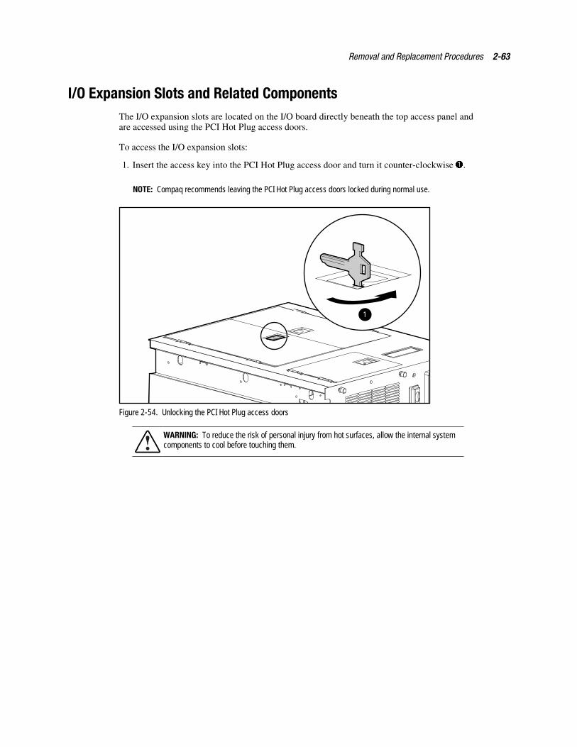
Removal and Replacement Procedures 2-63
I/O Expansion Slots and Related ComponentsThe I/O expansion slots are located on the I/O board directly beneath the top access panel andare accessed using the PCI Hot Plug access doors.
To access the I/O expansion slots:
1. Insert the access key into the PCI Hot Plug access door and turn it counter-clockwise �.
NOTE: Compaq recommends leaving the PCI Hot Plug access doors locked during normal use.
1
Figure 2-54. Unlocking the PCI Hot Plug access doors
WARNING: To reduce the risk of personal injury from hot surfaces, allow the internal systemcomponents to cool before touching them.
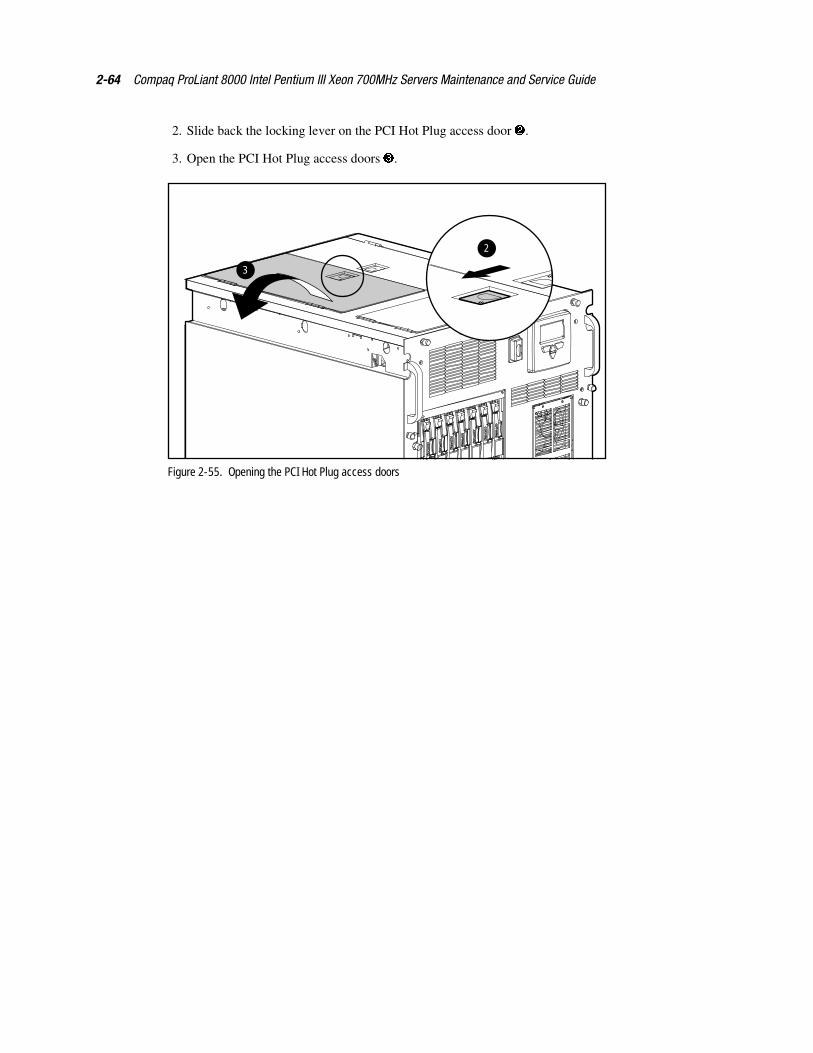
2-64 Compaq ProLiant 8000 Intel Pentium III Xeon 700MHz Servers Maintenance and Service Guide
2. Slide back the locking lever on the PCI Hot Plug access door �.
3. Open the PCI Hot Plug access doors �.
2
3
Figure 2-55. Opening the PCI Hot Plug access doors
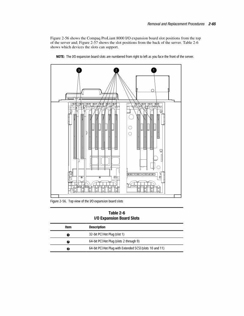
Removal and Replacement Procedures 2-65
Figure 2-56 shows the Compaq ProLiant 8000 I/O expansion board slot positions from the topof the server and; Figure 2-57 shows the slot positions from the back of the server. Table 2-6shows which devices the slots can support.
NOTE: The I/O expansion board slots are numbered from right to left as you face the front of the server.
123
Figure 2-56. Top view of the I/O expansion board slots
Table 2-6I/O Expansion Board Slots
Item Description
� 32-bit PCI Hot Plug (slot 1)
� 64-bit PCI Hot Plug (slots 2 through 9)
� 64-bit PCI Hot Plug with Extended SCSI (slots 10 and 11)
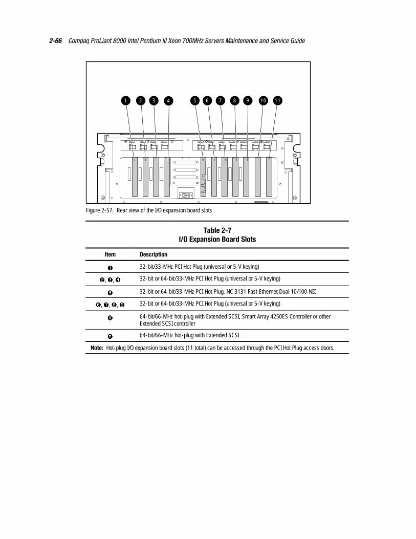
2-66 Compaq ProLiant 8000 Intel Pentium III Xeon 700MHz Servers Maintenance and Service Guide
1 2 3 4 5 6 7 8 9 10 11
Figure 2-57. Rear view of the I/O expansion board slots
Table 2-7I/O Expansion Board Slots
Item Description
� 32-bit/33-MHz PCI Hot Plug (universal or 5-V keying)
�, �, � 32-bit or 64-bit/33-MHz PCI Hot Plug (universal or 5-V keying)
32-bit or 64-bit/33-MHz PCI Hot Plug, NC 3131 Fast Ethernet Dual 10/100 NIC
�, , �, � 32-bit or 64-bit/33-MHz PCI Hot Plug (universal or 5-V keying)
� 64-bit/66-MHz hot-plug with Extended SCSI, Smart Array 4250ES Controller or otherExtended SCSI controller
� 64-bit/66-MHz hot-plug with Extended SCSI
Note: Hot-plug I/O expansion board slots (11 total) can be accessed through the PCI Hot Plug access doors.
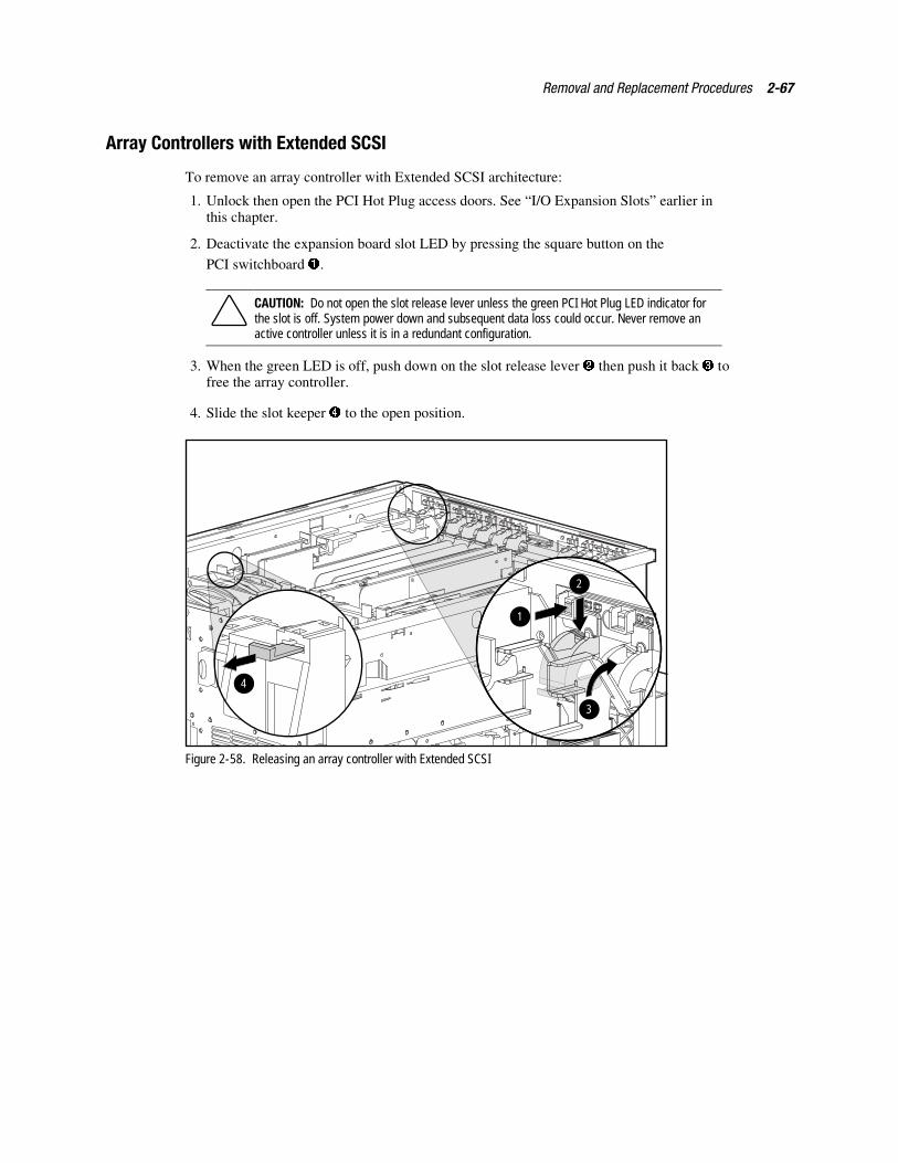
Removal and Replacement Procedures 2-67
Array Controllers with Extended SCSI
To remove an array controller with Extended SCSI architecture:
1. Unlock then open the PCI Hot Plug access doors. See “I/O Expansion Slots” earlier inthis chapter.
2. Deactivate the expansion board slot LED by pressing the square button on the
PCI switchboard �.
CAUTION: Do not open the slot release lever unless the green PCI Hot Plug LED indicator forthe slot is off. System power down and subsequent data loss could occur. Never remove anactive controller unless it is in a redundant configuration.
3. When the green LED is off, push down on the slot release lever � then push it back � tofree the array controller.
4. Slide the slot keeper � to the open position.
1
2
3
4
Figure 2-58. Releasing an array controller with Extended SCSI
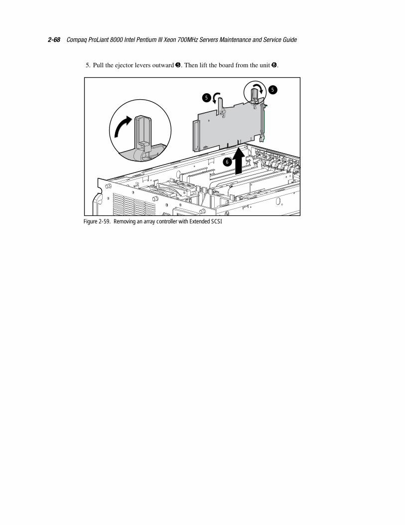
2-68 Compaq ProLiant 8000 Intel Pentium III Xeon 700MHz Servers Maintenance and Service Guide
5. Pull the ejector levers outward �. Then lift the board from the unit �.
6
5
5
Figure 2-59. Removing an array controller with Extended SCSI
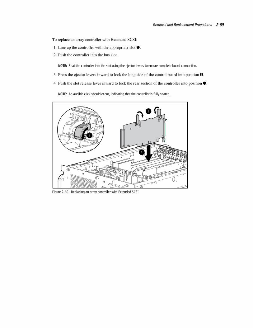
Removal and Replacement Procedures 2-69
To replace an array controller with Extended SCSI:
1. Line up the controller with the appropriate slot �.
2. Push the controller into the bus slot.
NOTE: Seat the controller into the slot using the ejector levers to ensure complete board connection.
3. Press the ejector levers inward to lock the long side of the control board into position �.
4. Push the slot release lever inward to lock the rear section of the controller into position �.
NOTE: An audible click should occur, indicating that the controller is fully seated.
1
2
3
Figure 2-60. Replacing an array controller with Extended SCSI
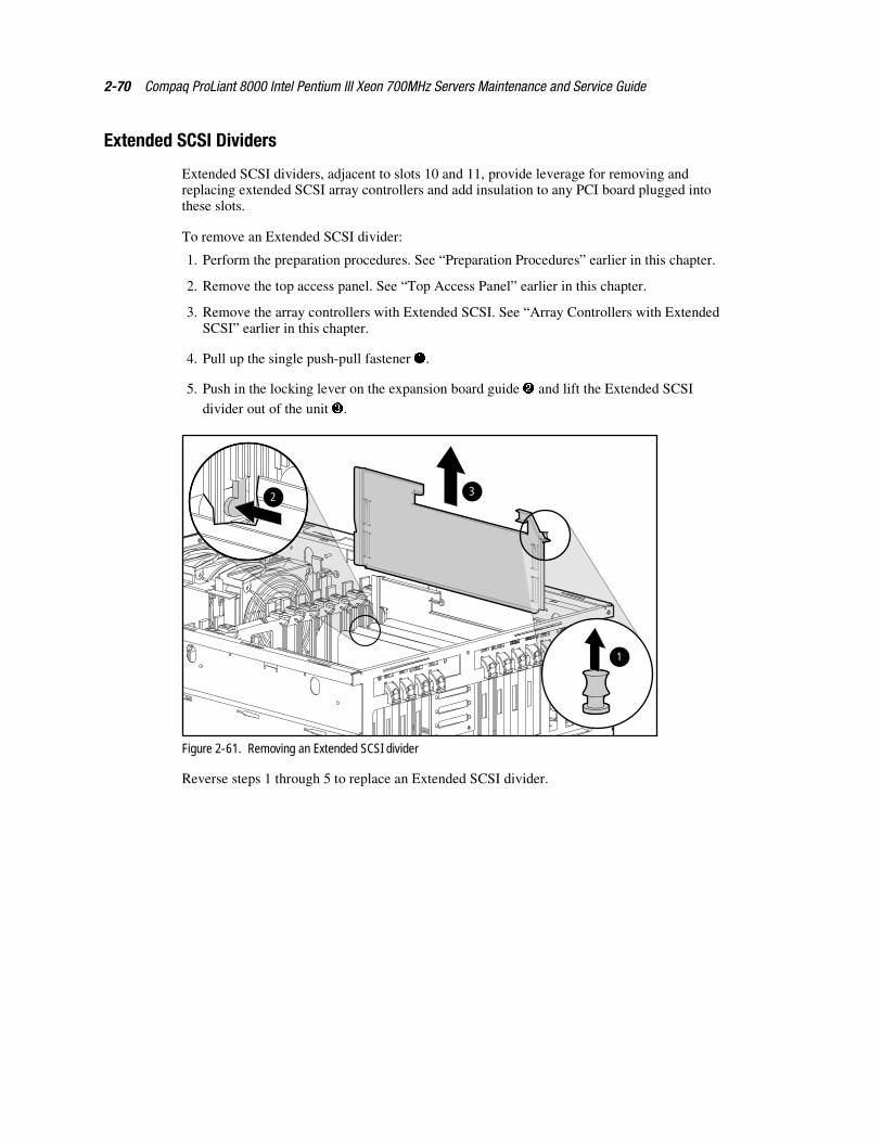
2-70 Compaq ProLiant 8000 Intel Pentium III Xeon 700MHz Servers Maintenance and Service Guide
Extended SCSI Dividers
Extended SCSI dividers, adjacent to slots 10 and 11, provide leverage for removing andreplacing extended SCSI array controllers and add insulation to any PCI board plugged intothese slots.
To remove an Extended SCSI divider:
1. Perform the preparation procedures. See “Preparation Procedures” earlier in this chapter.
2. Remove the top access panel. See “Top Access Panel” earlier in this chapter.
3. Remove the array controllers with Extended SCSI. See “Array Controllers with ExtendedSCSI” earlier in this chapter.
4. Pull up the single push-pull fastener �.
5. Push in the locking lever on the expansion board guide � and lift the Extended SCSI
divider out of the unit �.
2 3
1
Figure 2-61. Removing an Extended SCSI divider
Reverse steps 1 through 5 to replace an Extended SCSI divider.
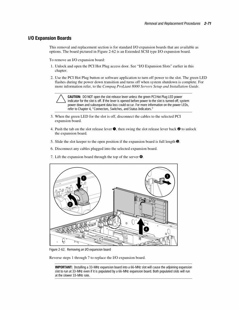
Removal and Replacement Procedures 2-71
I/O Expansion Boards
This removal and replacement section is for standard I/O expansion boards that are available asoptions. The board pictured in Figure 2-62 is an Extended SCSI type I/O expansion board.
To remove an I/O expansion board:
1. Unlock and open the PCI Hot Plug access door. See “I/O Expansion Slots” earlier in thischapter.
2. Use the PCI Hot Plug button or software application to turn off power to the slot. The green LEDflashes during the power down transition and turns off when system shutdown is complete. Formore information refer, to the Compaq ProLiant 8000 Servers Setup and Installation Guide.
CAUTION: DO NOT open the slot release lever unless the green PCI Hot Plug LED powerindicator for the slot is off. If the lever is opened before power to the slot is turned off, systempower down and subsequent data loss could occur. For more information on the power LEDs,refer to Chapter 4, “Connectors, Switches, and Status Indicators.”
3. When the green LED for the slot is off, disconnect the cables to the selected PCIexpansion board.
4. Push the tab on the slot release lever �, then swing the slot release lever back � to unlockthe expansion board.
5. Slide the slot keeper to the open position if the expansion board is full length �.
6. Disconnect any cables plugged into the selected expansion board.
7. Lift the expansion board through the top of the server �.
4
1
2
3
Figure 2-62. Removing an I/O expansion board
Reverse steps 1 through 7 to replace the I/O expansion board.
IMPORTANT: Installing a 33-MHz expansion board into a 66-MHz slot will cause the adjoining expansionslot to run at 33-MHz even if it is populated by a 66-MHz expansion board. Both populated slots will runat the slower 33-MHz rate.
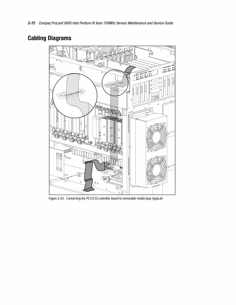
2-72 Compaq ProLiant 8000 Intel Pentium III Xeon 700MHz Servers Maintenance and Service Guide
Cabling Diagrams
Figure 2-63. Connecting the PCI SCSI controller board to removable media bays (typical)

Removal and Replacement Procedures 2-73
Cage 1
Cage 2
Cage 3
Figure 2-64. Connecting an array controller with Extended SCSI to drive cage 1, 2, or 3
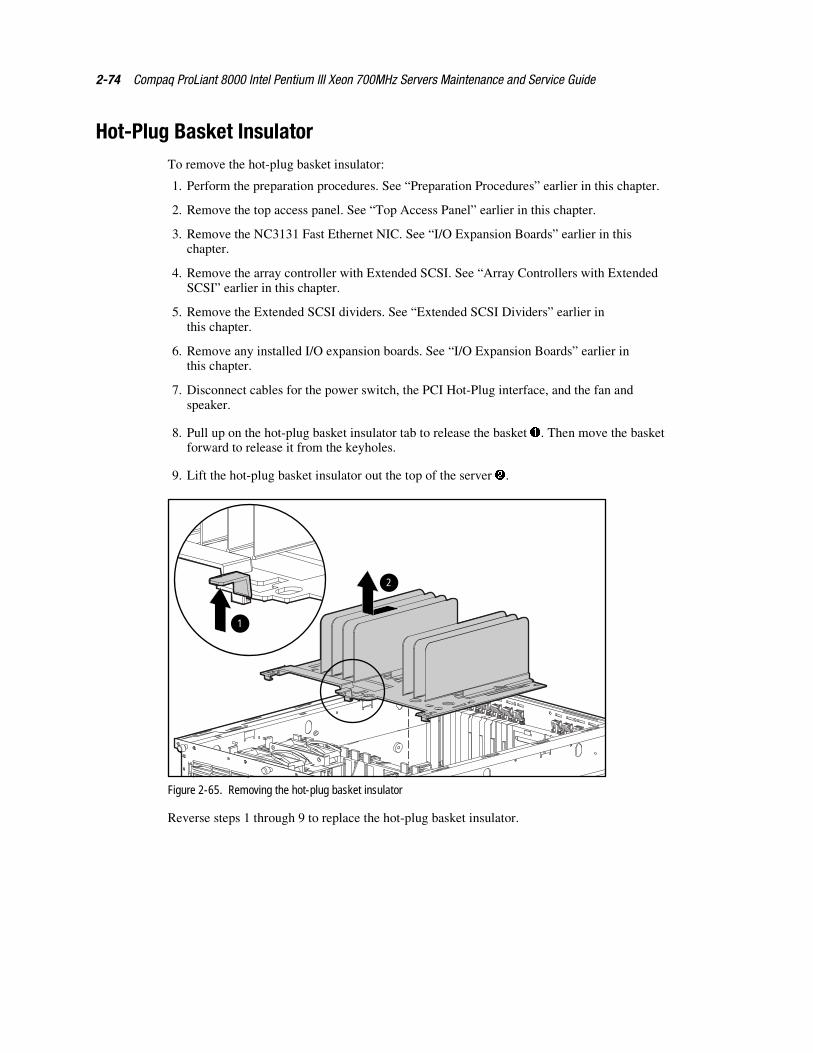
2-74 Compaq ProLiant 8000 Intel Pentium III Xeon 700MHz Servers Maintenance and Service Guide
Hot-Plug Basket InsulatorTo remove the hot-plug basket insulator:
1. Perform the preparation procedures. See “Preparation Procedures” earlier in this chapter.
2. Remove the top access panel. See “Top Access Panel” earlier in this chapter.
3. Remove the NC3131 Fast Ethernet NIC. See “I/O Expansion Boards” earlier in thischapter.
4. Remove the array controller with Extended SCSI. See “Array Controllers with ExtendedSCSI” earlier in this chapter.
5. Remove the Extended SCSI dividers. See “Extended SCSI Dividers” earlier inthis chapter.
6. Remove any installed I/O expansion boards. See “I/O Expansion Boards” earlier inthis chapter.
7. Disconnect cables for the power switch, the PCI Hot-Plug interface, and the fan andspeaker.
8. Pull up on the hot-plug basket insulator tab to release the basket �. Then move the basketforward to release it from the keyholes.
9. Lift the hot-plug basket insulator out the top of the server �.
1
2
Figure 2-65. Removing the hot-plug basket insulator
Reverse steps 1 through 9 to replace the hot-plug basket insulator.
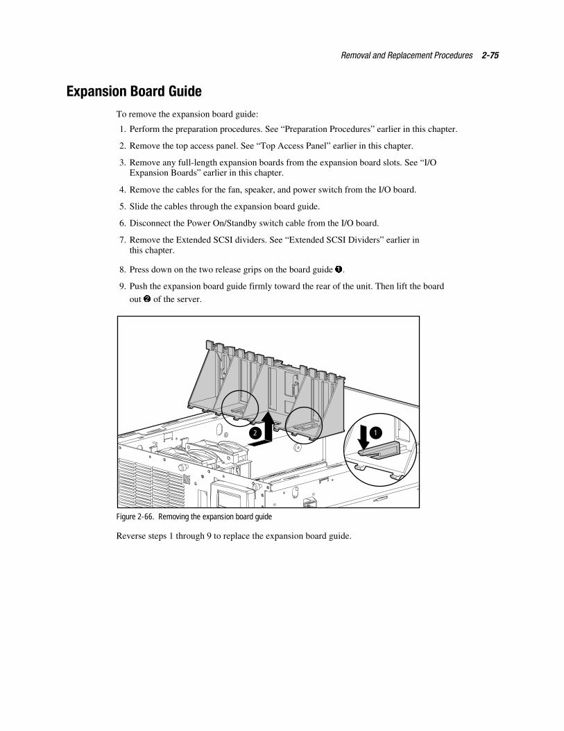
Removal and Replacement Procedures 2-75
Expansion Board GuideTo remove the expansion board guide:
1. Perform the preparation procedures. See “Preparation Procedures” earlier in this chapter.
2. Remove the top access panel. See “Top Access Panel” earlier in this chapter.
3. Remove any full-length expansion boards from the expansion board slots. See “I/OExpansion Boards” earlier in this chapter.
4. Remove the cables for the fan, speaker, and power switch from the I/O board.
5. Slide the cables through the expansion board guide.
6. Disconnect the Power On/Standby switch cable from the I/O board.
7. Remove the Extended SCSI dividers. See “Extended SCSI Dividers” earlier inthis chapter.
8. Press down on the two release grips on the board guide �.
9. Push the expansion board guide firmly toward the rear of the unit. Then lift the board
out � of the server.
12
Figure 2-66. Removing the expansion board guide
Reverse steps 1 through 9 to replace the expansion board guide.
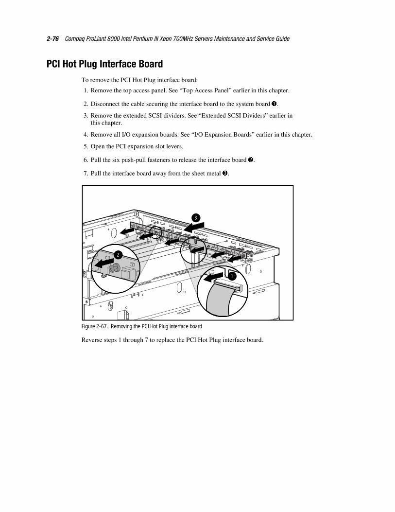
2-76 Compaq ProLiant 8000 Intel Pentium III Xeon 700MHz Servers Maintenance and Service Guide
PCI Hot Plug Interface BoardTo remove the PCI Hot Plug interface board:
1. Remove the top access panel. See “Top Access Panel” earlier in this chapter.
2. Disconnect the cable securing the interface board to the system board �.
3. Remove the extended SCSI dividers. See “Extended SCSI Dividers” earlier inthis chapter.
4. Remove all I/O expansion boards. See “I/O Expansion Boards” earlier in this chapter.
5. Open the PCI expansion slot levers.
6. Pull the six push-pull fasteners to release the interface board �.
7. Pull the interface board away from the sheet metal �.
3
1
2
Figure 2-67. Removing the PCI Hot Plug interface board
Reverse steps 1 through 7 to replace the PCI Hot Plug interface board.
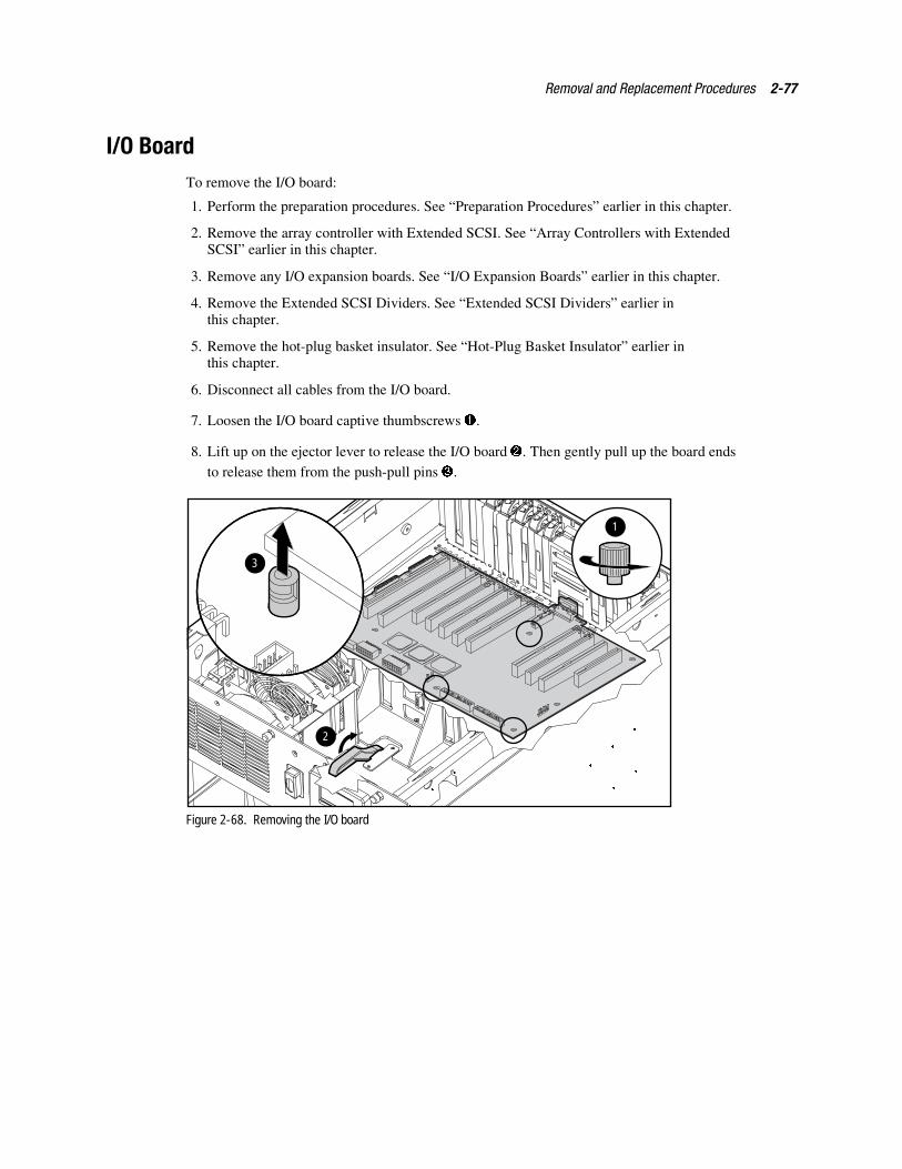
Removal and Replacement Procedures 2-77
I/O BoardTo remove the I/O board:
1. Perform the preparation procedures. See “Preparation Procedures” earlier in this chapter.
2. Remove the array controller with Extended SCSI. See “Array Controllers with ExtendedSCSI” earlier in this chapter.
3. Remove any I/O expansion boards. See “I/O Expansion Boards” earlier in this chapter.
4. Remove the Extended SCSI Dividers. See “Extended SCSI Dividers” earlier inthis chapter.
5. Remove the hot-plug basket insulator. See “Hot-Plug Basket Insulator” earlier inthis chapter.
6. Disconnect all cables from the I/O board.
7. Loosen the I/O board captive thumbscrews �.
8. Lift up on the ejector lever to release the I/O board �. Then gently pull up the board endsto release them from the push-pull pins �.
3
1
2
Figure 2-68. Removing the I/O board
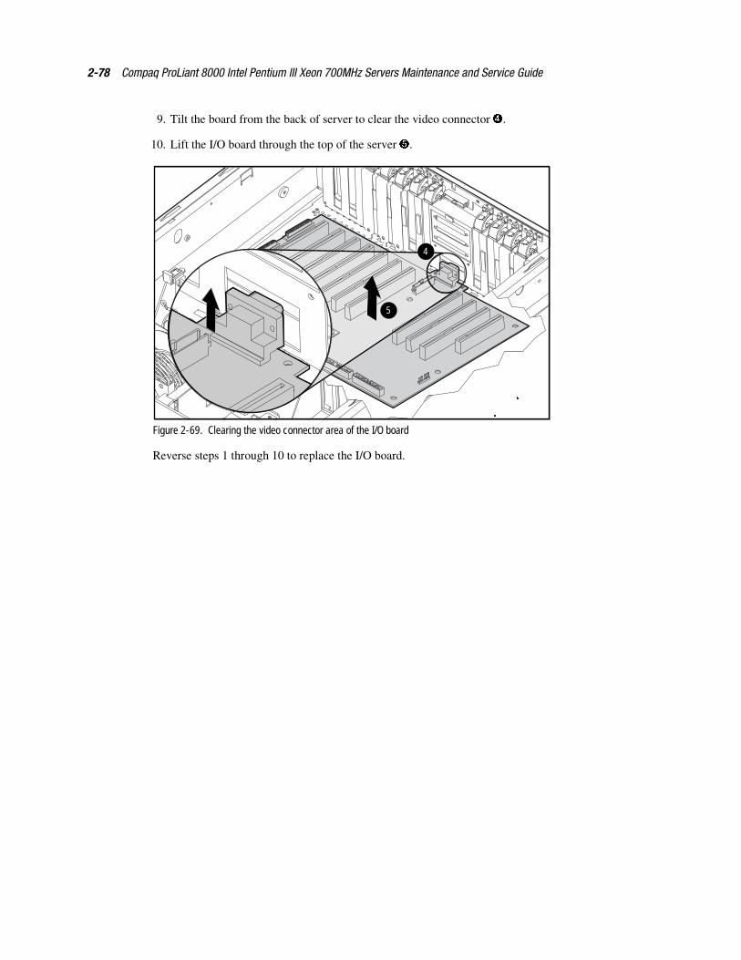
2-78 Compaq ProLiant 8000 Intel Pentium III Xeon 700MHz Servers Maintenance and Service Guide
9. Tilt the board from the back of server to clear the video connector �.
10. Lift the I/O board through the top of the server �.
5
4
Figure 2-69. Clearing the video connector area of the I/O board
Reverse steps 1 through 10 to replace the I/O board.
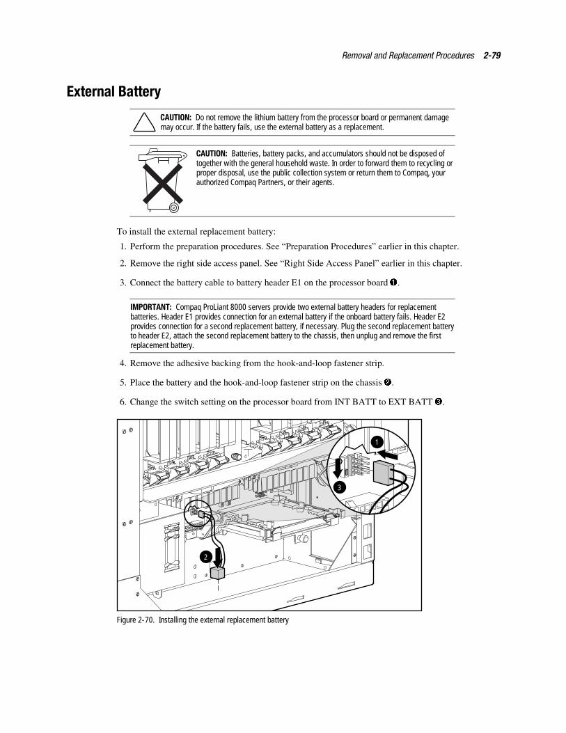
Removal and Replacement Procedures 2-79
External Battery
CAUTION: Do not remove the lithium battery from the processor board or permanent damagemay occur. If the battery fails, use the external battery as a replacement.
CAUTION: Batteries, battery packs, and accumulators should not be disposed oftogether with the general household waste. In order to forward them to recycling orproper disposal, use the public collection system or return them to Compaq, yourauthorized Compaq Partners, or their agents.
To install the external replacement battery:
1. Perform the preparation procedures. See “Preparation Procedures” earlier in this chapter.
2. Remove the right side access panel. See “Right Side Access Panel” earlier in this chapter.
3. Connect the battery cable to battery header E1 on the processor board �.
IMPORTANT: Compaq ProLiant 8000 servers provide two external battery headers for replacementbatteries. Header E1 provides connection for an external battery if the onboard battery fails. Header E2provides connection for a second replacement battery, if necessary. Plug the second replacement batteryto header E2, attach the second replacement battery to the chassis, then unplug and remove the firstreplacement battery.
4. Remove the adhesive backing from the hook-and-loop fastener strip.
5. Place the battery and the hook-and-loop fastener strip on the chassis �.
6. Change the switch setting on the processor board from INT BATT to EXT BATT �.
3
2
1
Figure 2-70. Installing the external replacement battery

2-80 Compaq ProLiant 8000 Intel Pentium III Xeon 700MHz Servers Maintenance and Service Guide
7. Place the sticker included with your battery kit on the back of your server above thepower connector.
IMPORTANT: You must run the Compaq System Configuration Utility to reconfigure the server afterinstalling a replacement battery.
Chapter 3Diagnostics and Troubleshooting
This chapter describes software and firmware diagnostic tools available for all Compaq serverproducts. The sections in this chapter are:
� Diagnostic Tools Utility Overview
� Default Configuration
� Utilities Access
� Power-On Self-Test
� Diagnostics Software
� Array Diagnostic Utility
� Integrated Management Log
� Rapid Error Recovery
� Remote Service Features
� ROMPaq Error Recovery Options
� Compaq Insight Manager
3-2 Compaq ProLiant 8000 Intel Pentium III Xeon 700MHz Servers Maintenance and Service Guide
Diagnostic Tools Utility OverviewThese utilities were developed to assist in diagnosing problems, testing the hardware, andmonitoring and managing Compaq server hardware.
Table 3-1Diagnostic Tools
Tool What it is How to run it
Compaq DiagnosticsProgram
Utility to assist testing and/or verifyingoperation of Compaq hardware. Ifproblems are found, CompaqDiagnostics isolates failure(s) down toreplaceable part, whenever possible.
Diagnostics and Utilities are located onthe system partition on the hard driveand must be accessed when a systemconfiguration error is detected duringPower-On Self-Test (POST). CompaqDiagnostics software is also available onthe Compaq SmartStart and SupportSoftware CD. A Diagnostics diskette canbe created from SmartStart and SupportSoftware CD.
Compaq InspectUtility
The Inspect Utility provides a reportdetailing system information.
The Inspect Utility can be run from eitherthe main menu of the SystemConfiguration Utility or the CompaqDiagnostics program.
Compaq InsightManager
A client/server application used toremotely manage Compaq hardware ina network environment. Reportshardware fault conditions (both failureand pre-failure) and collects data forreporting and graphing.
For more information, refer to theCompaq Management CD and theCompaq Insight Manager User Guide.
More information on viewing and printingthe event list can be found in the CompaqInsight Manager section of this chapter.
Compaq SurveyUtility
An online information gathering agentthat runs on servers, gathering criticalhardware and software informationfrom various sources. A utility forservers running Windows NT orNetWare.
If a significant change occurs betweendata gathering intervals, previousinformation is marked, and the surveytext file is overwritten to reflect thelatest configuration and changes sincelast configuration. This allows ahistorical record of change events forserver hardware and software.
Install Survey Utility from the SmartStartand Support Software CD, CompaqIntegration Maintenance Utility, or fromCompaq Management CD.
continued
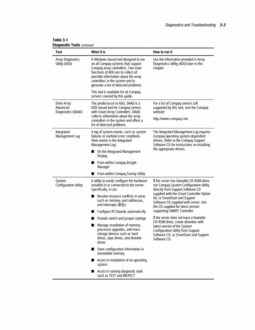
Diagnostics and Troubleshooting 3-3
Table 3-1Diagnostic Tools continued
Tool What it is How to run it
Array DiagnosticsUtility (ADU)
A Windows-based tool designed to runon all Compaq systems that supportCompaq array controllers. Two mainfunctions of ADU are to collect allpossible information about the arraycontrollers in the system and togenerate a list of detected problems.
This tool is available for all Compaqservers covered by this guide.
Use the information provided in ArrayDiagnostics Utility (ADU) later in thischapter.
Drive ArrayAdvancedDiagnostics (DAAD)
The predecessor to ADU, DAAD is aDOS-based tool for Compaq serverswith Smart Array Controllers. DAADcollects information about the arraycontrollers in the system and offers alist of detected problems.
For a list of Compaq servers stillsupported by this tool, visit the Compaqwebsite:
http://www.compaq.com
IntegratedManagement Log
A log of system events, such as systemfailures or nonfatal error conditions.View events in the IntegratedManagement Log:
� On the Integrated ManagementDisplay
� From within Compaq InsightManager
� From within Compaq Survey Utility
The Integrated Management Log requiresCompaq operating system-dependentdrivers. Refer to the Compaq SupportSoftware CD for instructions on installingthe appropriate drivers.
SystemConfiguration Utility
A utility to easily configure the hardwareinstalled in or connected to the server.Specifically, it can:
� Resolve resource conflicts in areassuch as memory, port addresses,and interrupts (IRQs)
� Configure PCI boards automatically
� Provide switch and jumper settings
� Manage installation of memory,processor upgrades, and massstorage devices such as harddrives, tape drives, and diskettedrives
� Store configuration information innonvolatile memory
� Assist in installation of an operatingsystem
� Assist in running diagnostic toolssuch as TEST and INSPECT
If the server has bootable CD-ROM drive,run Compaq System Configuration Utilitydirectly from Support Software CDsupplied with the Smart Controller OptionKit, or SmartStart and SupportSoftware CD supplied with server. Usethe CD supplied for latest versionsupporting SMART Controller.
If the server does not have a bootableCD-ROM drive, create diskettes withlatest version of the SystemConfiguration Utility from SupportSoftware CD, or SmartStart and SupportSoftware CD.
3-4 Compaq ProLiant 8000 Intel Pentium III Xeon 700MHz Servers Maintenance and Service Guide
Default ConfigurationWhen the system is first turned on, the system ROM detects the unconfigured state of thehardware and provides default configuration settings for most devices. By providing thisinitialization, the system can run Diagnostics and other software applications before running thenormal SmartStart and System Configuration programs.
Default Configuration Messages
IMPORTANT: Formatting and partitioning the boot drive before running SmartStart and the SystemConfiguration programs may prohibit creating a System Partition and the off-line remote managementfeatures that it provides.
If you insert a System Configuration, Diagnostics, or SmartStart and Support Software CD intothe CD-ROM drive before powering up the server, the system ROM boots to that utility. If thesystem ROM does not detect one of those CDs, you will be prompted to identify the intendedoperating system. The system reboots if any operating system-dependent configurations havechanged with the new operating system selection. If the selected operating system-dependentconfigurations are the same as the current configurations, the system boots normally. If youenter a wrong choice, on subsequent reboots you can change the operating system.
Inspect Utility
The Inspect Utility provides configuration information such as the contents of the operatingsystem startup files, the current memory configuration, the ROM version, and IntegratedManagement Log information. It operates with MS-DOS and in the MS-DOS emulation modeof OS/2.
Running the Inspect Utility
1. Turn off the server and then turn it back on and press F10 when the cursor appears in theupper right corner of the screen.
2. At the main menu, select Diagnostics and Utilities.
3. Press Enter.
4. Select Inspect Computer and press Enter.
NOTE: If Diagnostics is not installed on the hard drive, the System Configuration Utility prompts you toinsert the Diagnostics diskette into drive A.
5. Follow the instructions. The first time the Inspect Utility displays, select Entire Systemand press Enter.
Printing the Inspect Listing
Select Print on the Inspect screen to print a copy of the Inspect listing. Keep a copy of the listingwith each server for later reference.
Diagnostics and Troubleshooting 3-5
Utilities AccessThe Compaq SmartStart and Support Software CD contains the SmartStart program and manyof the Compaq utilities needed to maintain the system, including:
� System Configuration Utility
� Array Configuration Utility
� Array Diagnostic Utility
� ROMPaq Firmware Upgrade Utilities
� Compaq Diagnostics
CAUTION: Do not select the Erase Utility when running the SmartStart and SupportSoftware CD. This will result in data loss to the entire system.
Running Compaq Utilities
Compaq Utilities can be run from the system partition, from diskette, or from the CompaqSmartStart and Support Software CD.
Running the Utilities from the System Partition
If the system partition was installed using SmartStart, the Compaq utilities will automatically beavailable on the system partition. The system partition could also have been created during amanual system installation.
To run the utilities on the system partition, start the system and press F10 when you see:
Press F10 for system partition utilities.
Then select the desired utility from the menu:
� The System Configuration Utility is available under the System Configuration menu.
� The Array Configuration Utility is available under the System Configuration menu.
� Compaq Diagnostics (Test and Inspect) are available under the Diagnostics and Utilitiesmenu.
� The ROMPaq Firmware Upgrade Utility is available under the Diagnostics and Utilitiesmenu.
3-6 Compaq ProLiant 8000 Intel Pentium III Xeon 700MHz Servers Maintenance and Service Guide
Running the Utilities from Diskette
Run the utilities from their individual diskettes. If you have a utility diskette newer than theversion on the SmartStart and Support Software CD, use that diskette.
Create a diskette version of the utility from the SmartStart and Support Software CD.
To create diskette versions of the utilities from the CD:
1. Boot the Compaq SmartStart and Support Software CD.
2. From the Compaq System Utilities screen, select Create Support Software Disks, thenNext.
3. Select the diskette you would like to create from the list, then follow the instructions onthe screen.
Running the Utilities from the Compaq SmartStart and SupportSoftware CD
IMPORTANT: Only the System Configuration Utility, Array Configuration Utility, and Array DiagnosticUtility can be executed from the Compaq SmartStart and Support Software CD. All other utilities must beexecuted from the system partition or from diskette.
To run these utilities directly from the Compaq SmartStart and Support Software CD:
1. Boot the Compaq SmartStart and Support Software CD.
2. From the Compaq System Utilities screen, select the utility to run, then select Next.
� To execute the System Configuration Utility, select Run System Configuration Utility
� To execute the Array Configuration Utility, select Run Array Configuration Utility.
� To execute the Array Diagnostic Utility, select Run Array Diagnostic Utility.
Diagnostics and Troubleshooting 3-7
Power-On Self-TestThe Power-On Self-Test (POST) is a series of diagnostic tests that run automatically onCompaq computers when the system is turned on. POST checks the following assemblies toensure that the computer system is functioning properly:
� System ROM
� Keyboard
� System board
� Memory
� Memory expansion boards
� Controllers
� Diskette drives
� Hard drives
� Processor Power Modules
� Fans
POST Error Messages
If POST finds an error in the system, the error condition is indicated by an audible or visualmessage. If an error code displays on the screen during POST or after resetting the system, usethe instructions in the POST Error Messages table.
NOTE: Many of the actions listed require you to run Diagnostics or the Compaq System ConfigurationUtility. Steps for running these utilities are provided following the POST Error Messages tables.
The Recommended Action column lists the steps necessary to correct the problem. Aftercompleting each step, run the Diagnostics program to verify whether the error condition hasbeen corrected. If the error code reappears:
1. Perform the next step listed in the table.
2. Then run the Diagnostics program again.
3. Follow this procedure until Diagnostics no longer detects an error condition.
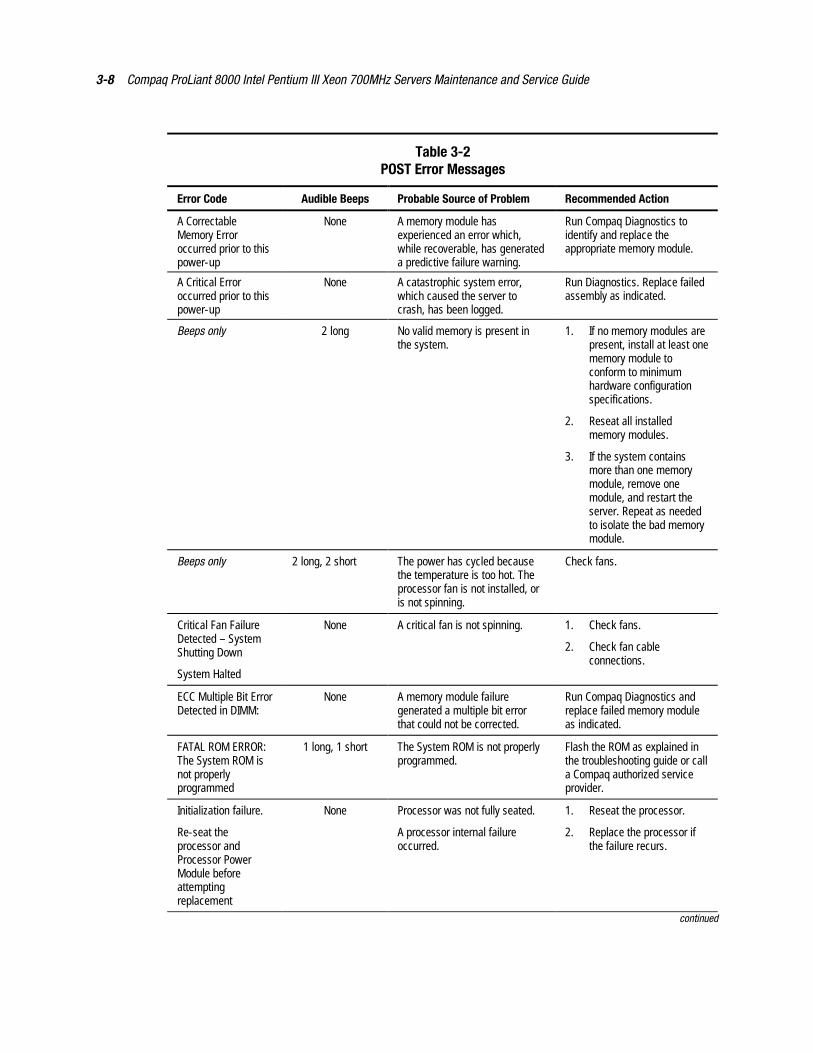
3-8 Compaq ProLiant 8000 Intel Pentium III Xeon 700MHz Servers Maintenance and Service Guide
Table 3-2POST Error Messages
Error Code Audible Beeps Probable Source of Problem Recommended Action
A CorrectableMemory Erroroccurred prior to thispower-up
None A memory module hasexperienced an error which,while recoverable, has generateda predictive failure warning.
Run Compaq Diagnostics toidentify and replace theappropriate memory module.
A Critical Erroroccurred prior to thispower-up
None A catastrophic system error,which caused the server tocrash, has been logged.
Run Diagnostics. Replace failedassembly as indicated.
Beeps only 2 long No valid memory is present inthe system.
1. If no memory modules arepresent, install at least onememory module toconform to minimumhardware configurationspecifications.
2. Reseat all installedmemory modules.
3. If the system containsmore than one memorymodule, remove onemodule, and restart theserver. Repeat as neededto isolate the bad memorymodule.
Beeps only 2 long, 2 short The power has cycled becausethe temperature is too hot. Theprocessor fan is not installed, oris not spinning.
Check fans.
Critical Fan FailureDetected – SystemShutting Down
System Halted
None A critical fan is not spinning. 1. Check fans.
2. Check fan cableconnections.
ECC Multiple Bit ErrorDetected in DIMM:
None A memory module failuregenerated a multiple bit errorthat could not be corrected.
Run Compaq Diagnostics andreplace failed memory moduleas indicated.
FATAL ROM ERROR:The System ROM isnot properlyprogrammed
1 long, 1 short The System ROM is not properlyprogrammed.
Flash the ROM as explained inthe troubleshooting guide or calla Compaq authorized serviceprovider.
Initialization failure.
Re-seat theprocessor andProcessor PowerModule beforeattemptingreplacement
None Processor was not fully seated.
A processor internal failureoccurred.
1. Reseat the processor.
2. Replace the processor ifthe failure recurs.
continued
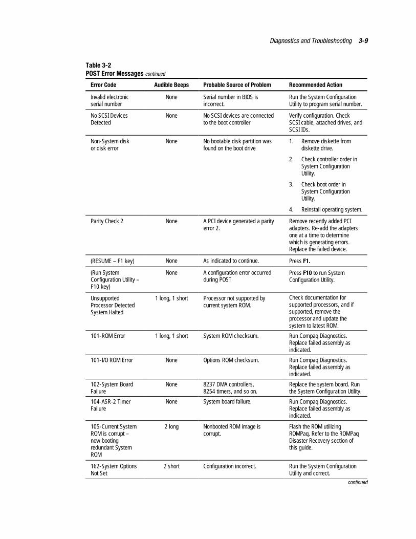
Diagnostics and Troubleshooting 3-9
Table 3-2POST Error Messages continued
Error Code Audible Beeps Probable Source of Problem Recommended Action
Invalid electronicserial number
None Serial number in BIOS isincorrect.
Run the System ConfigurationUtility to program serial number.
No SCSI DevicesDetected
None No SCSI devices are connectedto the boot controller
Verify configuration. CheckSCSI cable, attached drives, andSCSI IDs.
Non-System diskor disk error
None No bootable disk partition wasfound on the boot drive
1. Remove diskette fromdiskette drive.
2. Check controller order inSystem ConfigurationUtility.
3. Check boot order inSystem ConfigurationUtility.
4. Reinstall operating system.
Parity Check 2 None A PCI device generated a parityerror 2.
Remove recently added PCIadapters. Re-add the adaptersone at a time to determinewhich is generating errors.Replace the failed device.
(RESUME – F1 key) None As indicated to continue. Press F1.
(Run SystemConfiguration Utility –F10 key)
None A configuration error occurredduring POST
Press F10 to run SystemConfiguration Utility.
UnsupportedProcessor DetectedSystem Halted
1 long, 1 short Processor not supported bycurrent system ROM.
Check documentation forsupported processors, and ifsupported, remove theprocessor and update thesystem to latest ROM.
101-ROM Error 1 long, 1 short System ROM checksum. Run Compaq Diagnostics.Replace failed assembly asindicated.
101-I/O ROM Error None Options ROM checksum. Run Compaq Diagnostics.Replace failed assembly asindicated.
102-System BoardFailure
None 8237 DMA controllers,8254 timers, and so on.
Replace the system board. Runthe System Configuration Utility.
104-ASR-2 TimerFailure
None System board failure. Run Compaq Diagnostics.Replace failed assembly asindicated.
105-Current SystemROM is corrupt –now bootingredundant SystemROM
2 long Nonbooted ROM image iscorrupt.
Flash the ROM utilizingROMPaq. Refer to the ROMPaqDisaster Recovery section ofthis guide.
162-System OptionsNot Set
2 short Configuration incorrect. Run the System ConfigurationUtility and correct.
continued
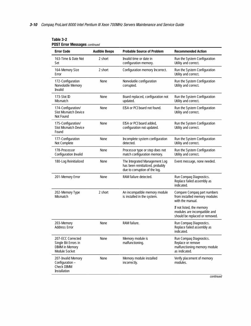
3-10 Compaq ProLiant 8000 Intel Pentium III Xeon 700MHz Servers Maintenance and Service Guide
Table 3-2POST Error Messages continued
Error Code Audible Beeps Probable Source of Problem Recommended Action
163-Time & Date NotSet
2 short Invalid time or date inconfiguration memory.
Run the System ConfigurationUtility and correct.
164-Memory SizeError
2 short Configuration memory Incorrect. Run the System ConfigurationUtility and correct.
172-ConfigurationNonvolatile MemoryInvalid
None Nonvolatile configurationcorrupted.
Run the System ConfigurationUtility and correct.
173-Slot IDMismatch
None Board replaced, configuration notupdated.
Run the System ConfigurationUtility and correct.
174-Configuration/Slot Mismatch DeviceNot Found
None EISA or PCI board not found. Run the System ConfigurationUtility and correct.
175-Configuration/Slot Mismatch DeviceFound
None EISA or PCI board added,configuration not updated.
Run the System ConfigurationUtility and correct.
177-ConfigurationNot Complete
None Incomplete system configurationdetected.
Run the System ConfigurationUtility and correct.
178-ProcessorConfiguration Invalid
None Processor type or step does notmatch configuration memory.
Run the System ConfigurationUtility and correct.
180-Log Reinitialized None The Integrated Management Loghas been reinitialized, probablydue to corruption of the log.
Event message, none needed.
201-Memory Error None RAM failure detected. Run Compaq Diagnostics.Replace failed assembly asindicated.
202-Memory TypeMismatch
2 short An incompatible memory moduleis installed in the system.
Compare Compaq part numbersfrom installed memory moduleswith the manual.
If not listed, the memorymodules are incompatible andshould be replaced or removed.
203-MemoryAddress Error
None RAM failure. Run Compaq Diagnostics.Replace failed assembly asindicated.
207-ECC CorrectedSingle Bit Errors inDIMM in MemoryModule Socket
None Memory module ismalfunctioning.
Run Compaq Diagnostics.Replace or removemalfunctioning memory moduleas indicated.
207-Invalid MemoryConfiguration –Check DIMMInstallation
None Memory module installedincorrectly.
Verify placement of memorymodules.
continued
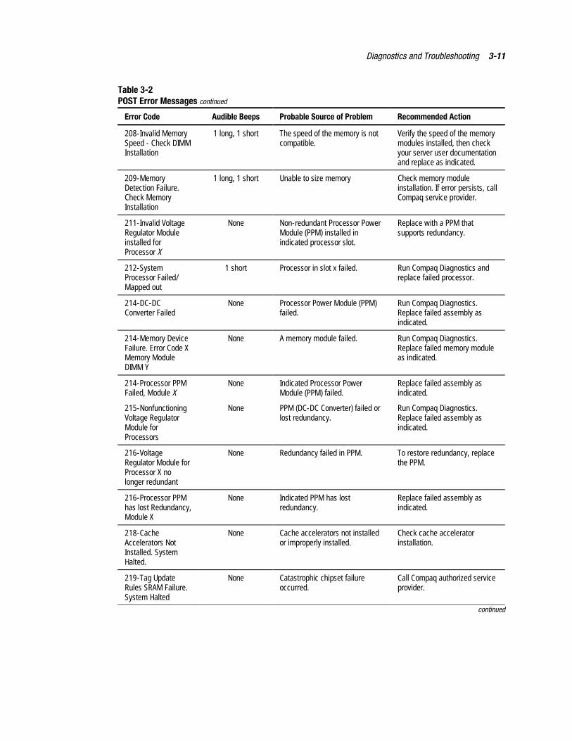
Diagnostics and Troubleshooting 3-11
Table 3-2POST Error Messages continued
Error Code Audible Beeps Probable Source of Problem Recommended Action
208-Invalid MemorySpeed - Check DIMMInstallation
1 long, 1 short The speed of the memory is notcompatible.
Verify the speed of the memorymodules installed, then checkyour server user documentationand replace as indicated.
209-MemoryDetection Failure.Check MemoryInstallation
1 long, 1 short Unable to size memory Check memory moduleinstallation. If error persists, callCompaq service provider.
211-Invalid VoltageRegulator Moduleinstalled forProcessor X
None Non-redundant Processor PowerModule (PPM) installed inindicated processor slot.
Replace with a PPM thatsupports redundancy.
212-SystemProcessor Failed/Mapped out
1 short Processor in slot x failed. Run Compaq Diagnostics andreplace failed processor.
214-DC-DCConverter Failed
None Processor Power Module (PPM)failed.
Run Compaq Diagnostics.Replace failed assembly asindicated.
214-Memory DeviceFailure. Error Code XMemory ModuleDIMM Y
None A memory module failed. Run Compaq Diagnostics.Replace failed memory moduleas indicated.
214-Processor PPMFailed, Module X
None Indicated Processor PowerModule (PPM) failed.
Replace failed assembly asindicated.
215-NonfunctioningVoltage RegulatorModule forProcessors
None PPM (DC-DC Converter) failed orlost redundancy.
Run Compaq Diagnostics.Replace failed assembly asindicated.
216-VoltageRegulator Module forProcessor X nolonger redundant
None Redundancy failed in PPM. To restore redundancy, replacethe PPM.
216-Processor PPMhas lost Redundancy,Module X
None Indicated PPM has lostredundancy.
Replace failed assembly asindicated.
218-CacheAccelerators NotInstalled. SystemHalted.
None Cache accelerators not installedor improperly installed.
Check cache acceleratorinstallation.
219-Tag UpdateRules SRAM Failure.System Halted
None Catastrophic chipset failureoccurred.
Call Compaq authorized serviceprovider.
continued
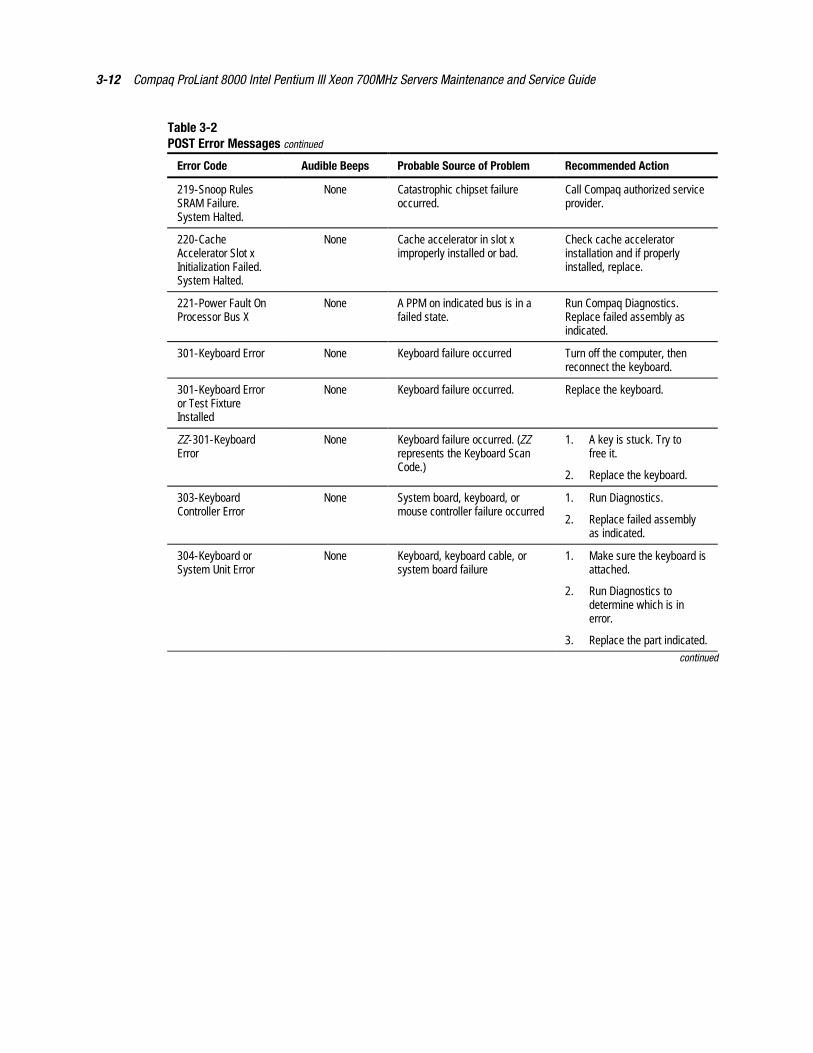
3-12 Compaq ProLiant 8000 Intel Pentium III Xeon 700MHz Servers Maintenance and Service Guide
Table 3-2POST Error Messages continued
Error Code Audible Beeps Probable Source of Problem Recommended Action
219-Snoop RulesSRAM Failure.System Halted.
None Catastrophic chipset failureoccurred.
Call Compaq authorized serviceprovider.
220-CacheAccelerator Slot xInitialization Failed.System Halted.
None Cache accelerator in slot ximproperly installed or bad.
Check cache acceleratorinstallation and if properlyinstalled, replace.
221-Power Fault OnProcessor Bus X
None A PPM on indicated bus is in afailed state.
Run Compaq Diagnostics.Replace failed assembly asindicated.
301-Keyboard Error None Keyboard failure occurred Turn off the computer, thenreconnect the keyboard.
301-Keyboard Erroror Test FixtureInstalled
None Keyboard failure occurred. Replace the keyboard.
ZZ-301-KeyboardError
None Keyboard failure occurred. (ZZrepresents the Keyboard ScanCode.)
1. A key is stuck. Try tofree it.
2. Replace the keyboard.
303-KeyboardController Error
None System board, keyboard, ormouse controller failure occurred
1. Run Diagnostics.
2. Replace failed assemblyas indicated.
304-Keyboard orSystem Unit Error
None Keyboard, keyboard cable, orsystem board failure
1. Make sure the keyboard isattached.
2. Run Diagnostics todetermine which is inerror.
3. Replace the part indicated.continued
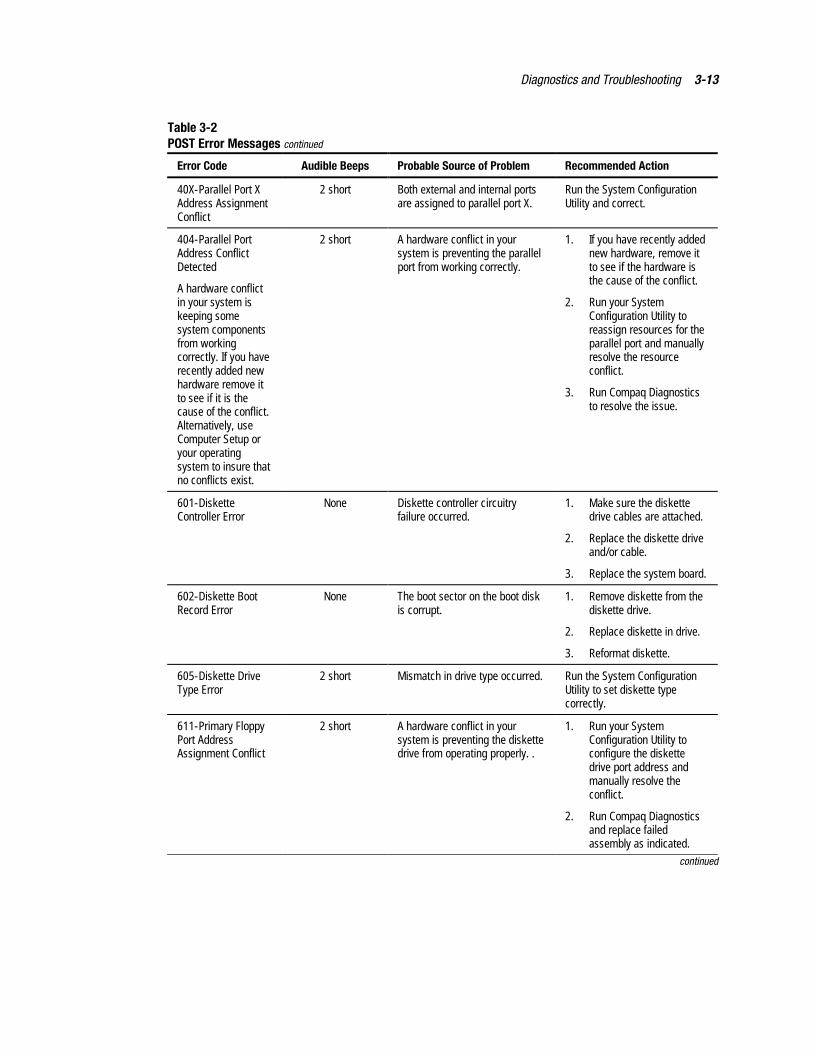
Diagnostics and Troubleshooting 3-13
Table 3-2POST Error Messages continued
Error Code Audible Beeps Probable Source of Problem Recommended Action
40X-Parallel Port XAddress AssignmentConflict
2 short Both external and internal portsare assigned to parallel port X.
Run the System ConfigurationUtility and correct.
404-Parallel PortAddress ConflictDetected
A hardware conflictin your system iskeeping somesystem componentsfrom workingcorrectly. If you haverecently added newhardware remove itto see if it is thecause of the conflict.Alternatively, useComputer Setup oryour operatingsystem to insure thatno conflicts exist.
2 short A hardware conflict in yoursystem is preventing the parallelport from working correctly.
1. If you have recently addednew hardware, remove itto see if the hardware isthe cause of the conflict.
2. Run your SystemConfiguration Utility toreassign resources for theparallel port and manuallyresolve the resourceconflict.
3. Run Compaq Diagnosticsto resolve the issue.
601-DisketteController Error
None Diskette controller circuitryfailure occurred.
1. Make sure the diskettedrive cables are attached.
2. Replace the diskette driveand/or cable.
3. Replace the system board.
602-Diskette BootRecord Error
None The boot sector on the boot diskis corrupt.
1. Remove diskette from thediskette drive.
2. Replace diskette in drive.
3. Reformat diskette.
605-Diskette DriveType Error
2 short Mismatch in drive type occurred. Run the System ConfigurationUtility to set diskette typecorrectly.
611-Primary FloppyPort AddressAssignment Conflict
2 short A hardware conflict in yoursystem is preventing the diskettedrive from operating properly. .
1. Run your SystemConfiguration Utility toconfigure the diskettedrive port address andmanually resolve theconflict.
2. Run Compaq Diagnosticsand replace failedassembly as indicated.
continued
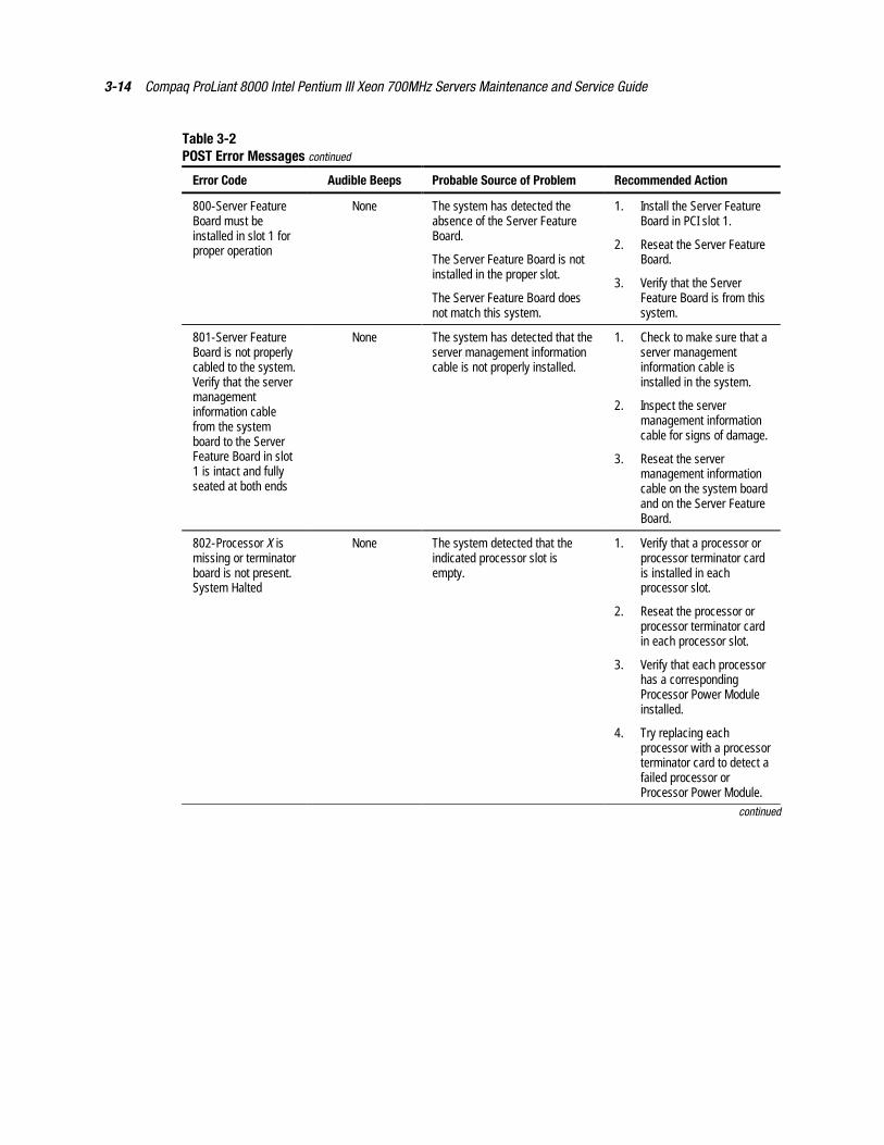
3-14 Compaq ProLiant 8000 Intel Pentium III Xeon 700MHz Servers Maintenance and Service Guide
Table 3-2POST Error Messages continued
Error Code Audible Beeps Probable Source of Problem Recommended Action
800-Server FeatureBoard must beinstalled in slot 1 forproper operation
None The system has detected theabsence of the Server FeatureBoard.
The Server Feature Board is notinstalled in the proper slot.
The Server Feature Board doesnot match this system.
1. Install the Server FeatureBoard in PCI slot 1.
2. Reseat the Server FeatureBoard.
3. Verify that the ServerFeature Board is from thissystem.
801-Server FeatureBoard is not properlycabled to the system.Verify that the servermanagementinformation cablefrom the systemboard to the ServerFeature Board in slot1 is intact and fullyseated at both ends
None The system has detected that theserver management informationcable is not properly installed.
1. Check to make sure that aserver managementinformation cable isinstalled in the system.
2. Inspect the servermanagement informationcable for signs of damage.
3. Reseat the servermanagement informationcable on the system boardand on the Server FeatureBoard.
802-Processor X ismissing or terminatorboard is not present.System Halted
None The system detected that theindicated processor slot isempty.
1. Verify that a processor orprocessor terminator cardis installed in eachprocessor slot.
2. Reseat the processor orprocessor terminator cardin each processor slot.
3. Verify that each processorhas a correspondingProcessor Power Moduleinstalled.
4. Try replacing eachprocessor with a processorterminator card to detect afailed processor orProcessor Power Module.
continued
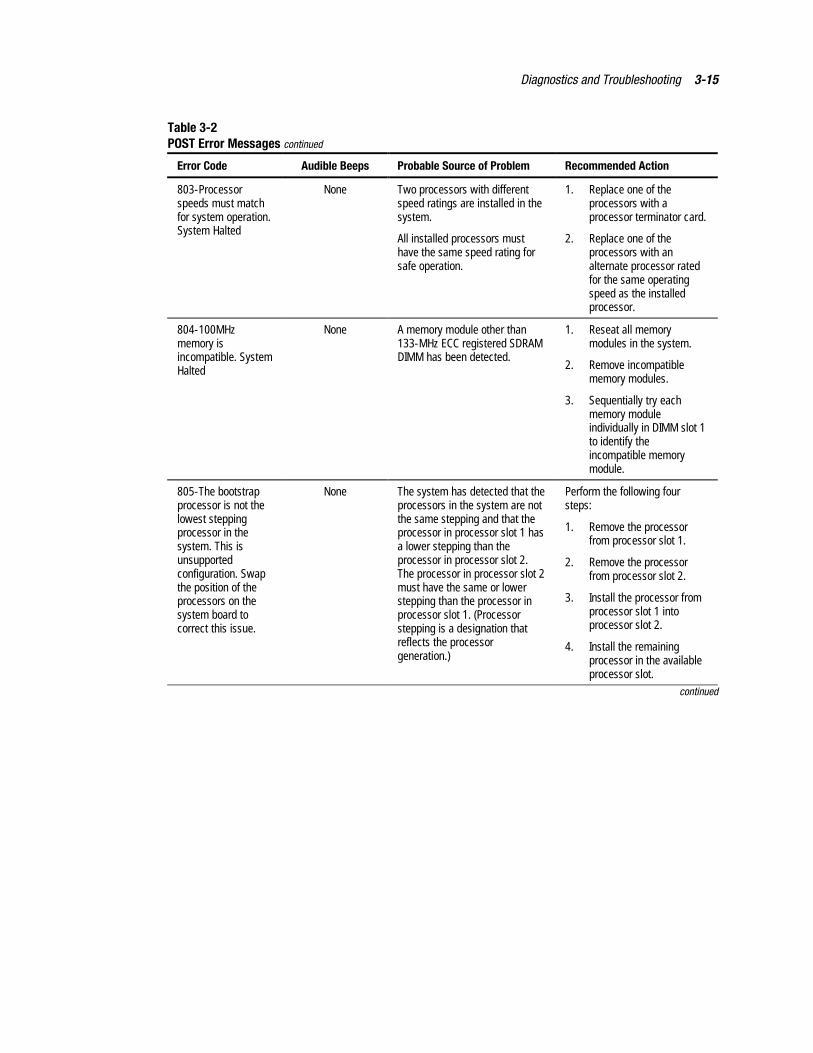
Diagnostics and Troubleshooting 3-15
Table 3-2POST Error Messages continued
Error Code Audible Beeps Probable Source of Problem Recommended Action
803-Processorspeeds must matchfor system operation.System Halted
None Two processors with differentspeed ratings are installed in thesystem.
All installed processors musthave the same speed rating forsafe operation.
1. Replace one of theprocessors with aprocessor terminator card.
2. Replace one of theprocessors with analternate processor ratedfor the same operatingspeed as the installedprocessor.
804-100MHzmemory isincompatible. SystemHalted
None A memory module other than133-MHz ECC registered SDRAMDIMM has been detected.
1. Reseat all memorymodules in the system.
2. Remove incompatiblememory modules.
3. Sequentially try eachmemory moduleindividually in DIMM slot 1to identify theincompatible memorymodule.
805-The bootstrapprocessor is not thelowest steppingprocessor in thesystem. This isunsupportedconfiguration. Swapthe position of theprocessors on thesystem board tocorrect this issue.
None The system has detected that theprocessors in the system are notthe same stepping and that theprocessor in processor slot 1 hasa lower stepping than theprocessor in processor slot 2.The processor in processor slot 2must have the same or lowerstepping than the processor inprocessor slot 1. (Processorstepping is a designation thatreflects the processorgeneration.)
Perform the following foursteps:
1. Remove the processorfrom processor slot 1.
2. Remove the processorfrom processor slot 2.
3. Install the processor fromprocessor slot 1 intoprocessor slot 2.
4. Install the remainingprocessor in the availableprocessor slot.
continued
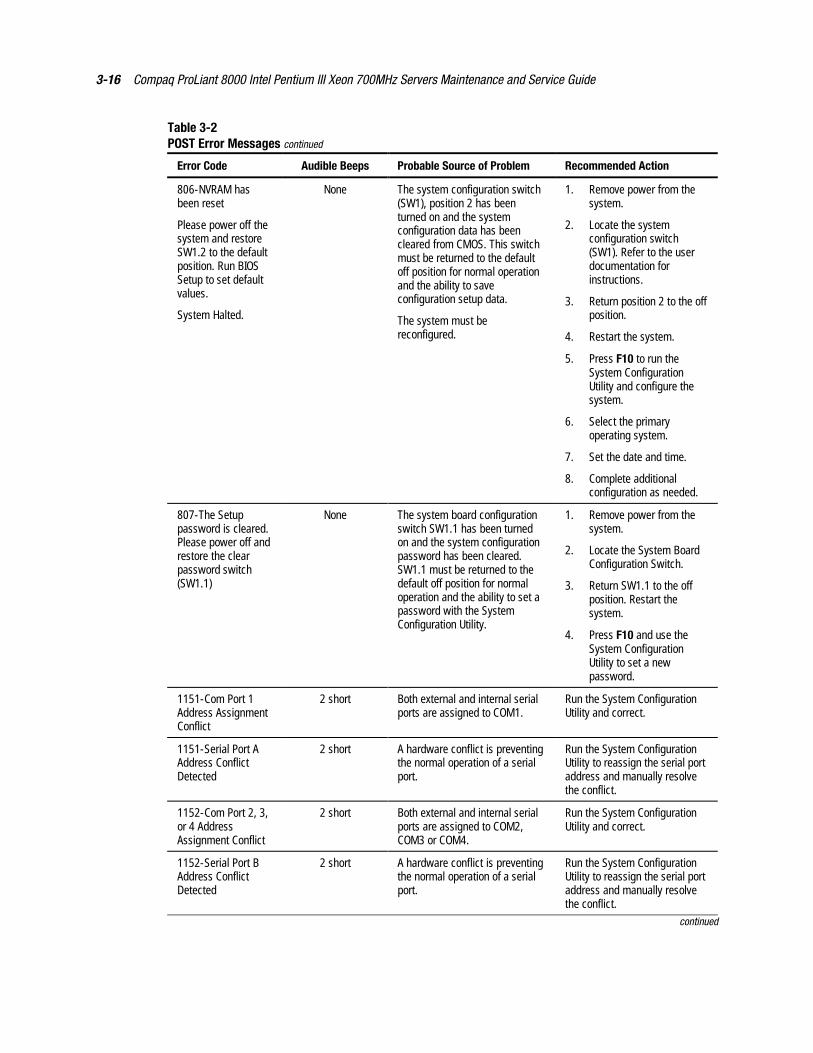
3-16 Compaq ProLiant 8000 Intel Pentium III Xeon 700MHz Servers Maintenance and Service Guide
Table 3-2POST Error Messages continued
Error Code Audible Beeps Probable Source of Problem Recommended Action
806-NVRAM hasbeen reset
Please power off thesystem and restoreSW1.2 to the defaultposition. Run BIOSSetup to set defaultvalues.
System Halted.
None The system configuration switch(SW1), position 2 has beenturned on and the systemconfiguration data has beencleared from CMOS. This switchmust be returned to the defaultoff position for normal operationand the ability to saveconfiguration setup data.
The system must bereconfigured.
1. Remove power from thesystem.
2. Locate the systemconfiguration switch(SW1). Refer to the userdocumentation forinstructions.
3. Return position 2 to the offposition.
4. Restart the system.
5. Press F10 to run theSystem ConfigurationUtility and configure thesystem.
6. Select the primaryoperating system.
7. Set the date and time.
8. Complete additionalconfiguration as needed.
807-The Setuppassword is cleared.Please power off andrestore the clearpassword switch(SW1.1)
None The system board configurationswitch SW1.1 has been turnedon and the system configurationpassword has been cleared.SW1.1 must be returned to thedefault off position for normaloperation and the ability to set apassword with the SystemConfiguration Utility.
1. Remove power from thesystem.
2. Locate the System BoardConfiguration Switch.
3. Return SW1.1 to the offposition. Restart thesystem.
4. Press F10 and use theSystem ConfigurationUtility to set a newpassword.
1151-Com Port 1Address AssignmentConflict
2 short Both external and internal serialports are assigned to COM1.
Run the System ConfigurationUtility and correct.
1151-Serial Port AAddress ConflictDetected
2 short A hardware conflict is preventingthe normal operation of a serialport.
Run the System ConfigurationUtility to reassign the serial portaddress and manually resolvethe conflict.
1152-Com Port 2, 3,or 4 AddressAssignment Conflict
2 short Both external and internal serialports are assigned to COM2,COM3 or COM4.
Run the System ConfigurationUtility and correct.
1152-Serial Port BAddress ConflictDetected
2 short A hardware conflict is preventingthe normal operation of a serialport.
Run the System ConfigurationUtility to reassign the serial portaddress and manually resolvethe conflict.
continued
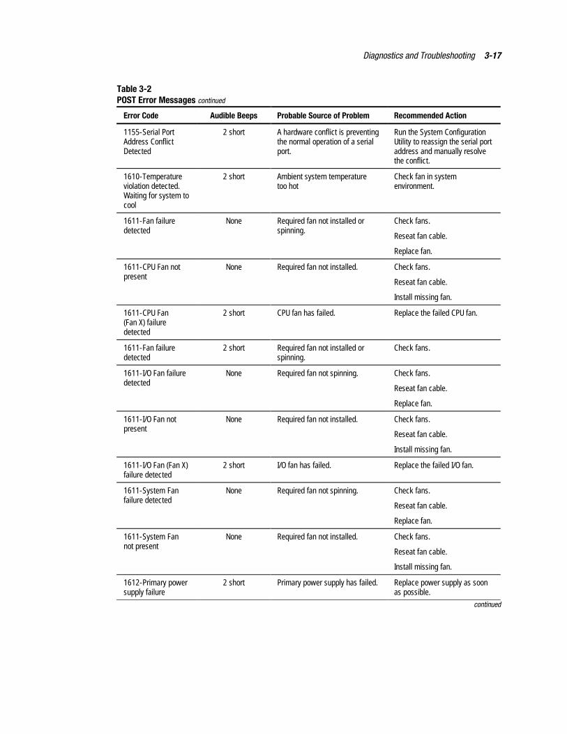
Diagnostics and Troubleshooting 3-17
Table 3-2POST Error Messages continued
Error Code Audible Beeps Probable Source of Problem Recommended Action
1155-Serial PortAddress ConflictDetected
2 short A hardware conflict is preventingthe normal operation of a serialport.
Run the System ConfigurationUtility to reassign the serial portaddress and manually resolvethe conflict.
1610-Temperatureviolation detected.Waiting for system tocool
2 short Ambient system temperaturetoo hot
Check fan in systemenvironment.
1611-Fan failuredetected
None Required fan not installed orspinning.
Check fans.
Reseat fan cable.
Replace fan.
1611-CPU Fan notpresent
None Required fan not installed. Check fans.
Reseat fan cable.
Install missing fan.
1611-CPU Fan(Fan X) failuredetected
2 short CPU fan has failed. Replace the failed CPU fan.
1611-Fan failuredetected
2 short Required fan not installed orspinning.
Check fans.
1611-I/O Fan failuredetected
None Required fan not spinning. Check fans.
Reseat fan cable.
Replace fan.
1611-I/O Fan notpresent
None Required fan not installed. Check fans.
Reseat fan cable.
Install missing fan.
1611-I/O Fan (Fan X)failure detected
2 short I/O fan has failed. Replace the failed I/O fan.
1611-System Fanfailure detected
None Required fan not spinning. Check fans.
Reseat fan cable.
Replace fan.
1611-System Fannot present
None Required fan not installed. Check fans.
Reseat fan cable.
Install missing fan.
1612-Primary powersupply failure
2 short Primary power supply has failed. Replace power supply as soonas possible.
continued
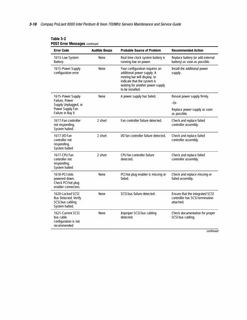
3-18 Compaq ProLiant 8000 Intel Pentium III Xeon 700MHz Servers Maintenance and Service Guide
Table 3-2POST Error Messages continued
Error Code Audible Beeps Probable Source of Problem Recommended Action
1613-Low SystemBattery
None Real time clock system battery isrunning low on power.
Replace battery (or add externalbattery) as soon as possible.
1615-Power Supplyconfiguration error
None Your configuration requires anadditional power supply. Amoving bar will display, toindicate that the system iswaiting for another power supplyto be installed.
Install the additional powersupply.
1615-Power SupplyFailure, PowerSupply Unplugged, orPower Supply FanFailure in Bay X
None A power supply has failed. Reseat power supply firmly.
-Or-
Replace power supply as soonas possible.
1617-Fan controllernot responding.System halted.
2 short Fan controller failure detected. Check and replace failedcontroller assembly.
1617-I/O Fancontroller notresponding.System halted
2 short I/O fan controller failure detected. Check and replace failedcontroller assembly.
1617-CPU Fancontroller notresponding.System halted
2 short CPU fan controller failuredetected.
Check and replace failedcontroller assembly.
1618-PCI slotspowered down.Check PCI hot plugenabler connectors.
None PCI hot plug enabler is missing orfailed.
Check and replace missing orfailed assembly.
1620-Locked SCSIBus Detected. VerifySCSI bus cabling.System halted.
None SCSI bus failure detected. Ensure that the integrated SCSIcontroller has SCSI terminationattached.
1621-Current SCSIbus cableconfiguration is notrecommended
None Improper SCSI bus cablingdetected.
Check documentation for properSCSI bus cabling.
continued
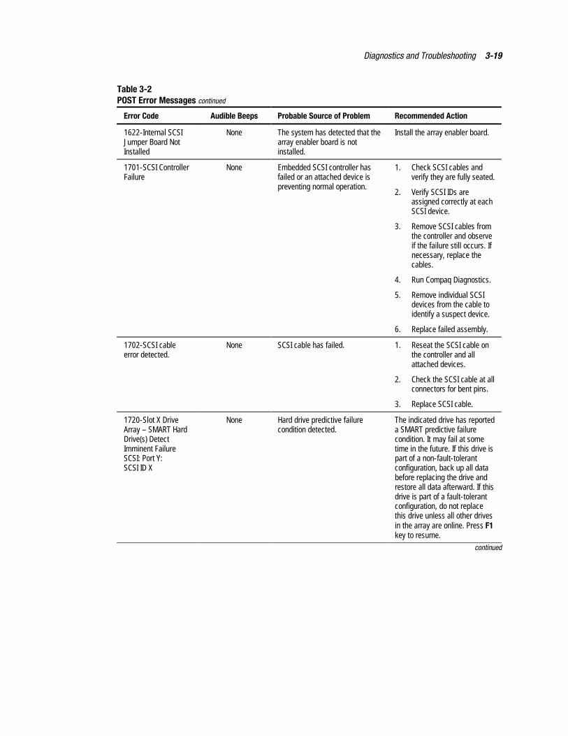
Diagnostics and Troubleshooting 3-19
Table 3-2POST Error Messages continued
Error Code Audible Beeps Probable Source of Problem Recommended Action
1622-Internal SCSIJumper Board NotInstalled
None The system has detected that thearray enabler board is notinstalled.
Install the array enabler board.
1701-SCSI ControllerFailure
None Embedded SCSI controller hasfailed or an attached device ispreventing normal operation.
1. Check SCSI cables andverify they are fully seated.
2. Verify SCSI IDs areassigned correctly at eachSCSI device.
3. Remove SCSI cables fromthe controller and observeif the failure still occurs. Ifnecessary, replace thecables.
4. Run Compaq Diagnostics.
5. Remove individual SCSIdevices from the cable toidentify a suspect device.
6. Replace failed assembly.
1702-SCSI cableerror detected.
None SCSI cable has failed. 1. Reseat the SCSI cable onthe controller and allattached devices.
2. Check the SCSI cable at allconnectors for bent pins.
3. Replace SCSI cable.
1720-Slot X DriveArray – SMART HardDrive(s) DetectImminent FailureSCSI: Port Y:SCSI ID X
None Hard drive predictive failurecondition detected.
The indicated drive has reporteda SMART predictive failurecondition. It may fail at sometime in the future. If this drive ispart of a non-fault-tolerantconfiguration, back up all databefore replacing the drive andrestore all data afterward. If thisdrive is part of a fault-tolerantconfiguration, do not replacethis drive unless all other drivesin the array are online. Press F1key to resume.
continued
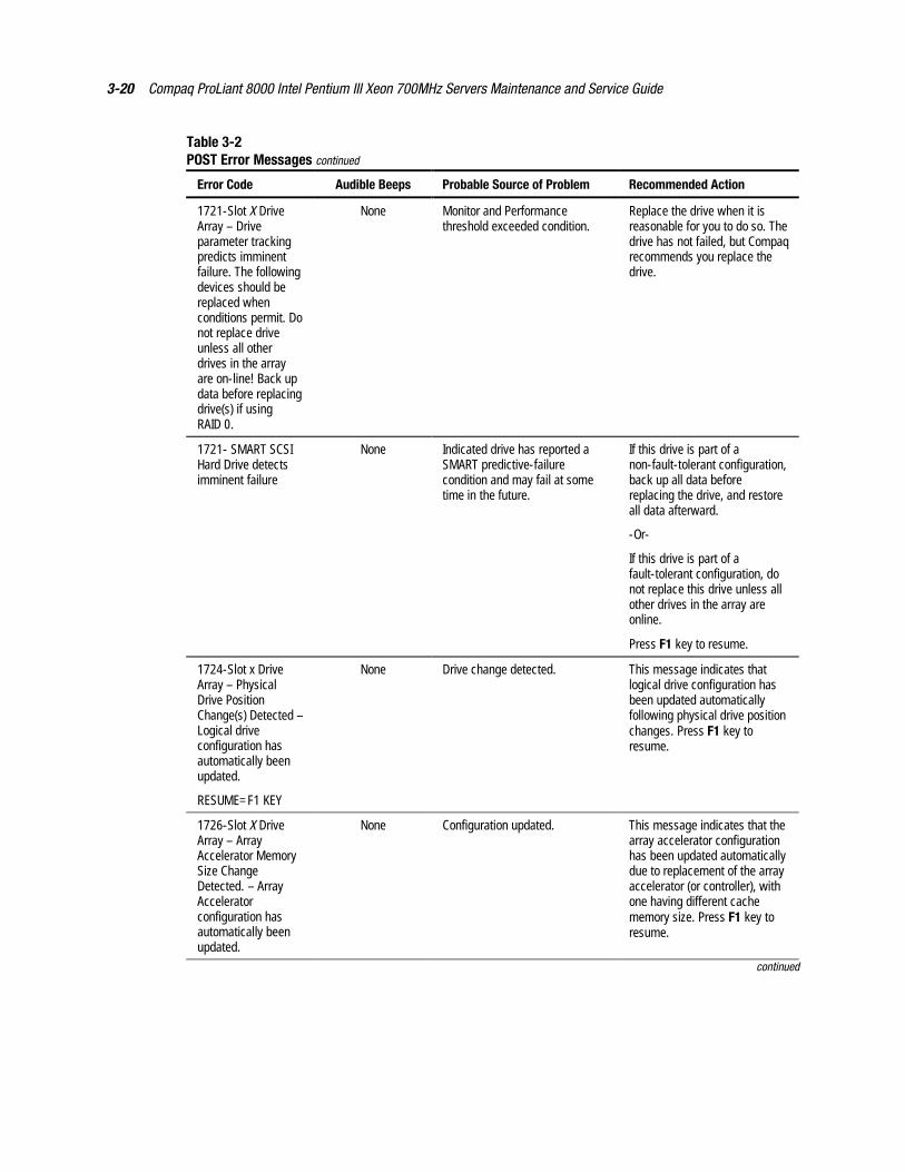
3-20 Compaq ProLiant 8000 Intel Pentium III Xeon 700MHz Servers Maintenance and Service Guide
Table 3-2POST Error Messages continued
Error Code Audible Beeps Probable Source of Problem Recommended Action
1721-Slot X DriveArray – Driveparameter trackingpredicts imminentfailure. The followingdevices should bereplaced whenconditions permit. Donot replace driveunless all otherdrives in the arrayare on-line! Back updata before replacingdrive(s) if usingRAID 0.
None Monitor and Performancethreshold exceeded condition.
Replace the drive when it isreasonable for you to do so. Thedrive has not failed, but Compaqrecommends you replace thedrive.
1721- SMART SCSIHard Drive detectsimminent failure
None Indicated drive has reported aSMART predictive-failurecondition and may fail at sometime in the future.
If this drive is part of anon-fault-tolerant configuration,back up all data beforereplacing the drive, and restoreall data afterward.
-Or-
If this drive is part of afault-tolerant configuration, donot replace this drive unless allother drives in the array areonline.
Press F1 key to resume.
1724-Slot x DriveArray – PhysicalDrive PositionChange(s) Detected –Logical driveconfiguration hasautomatically beenupdated.
RESUME=F1 KEY
None Drive change detected. This message indicates thatlogical drive configuration hasbeen updated automaticallyfollowing physical drive positionchanges. Press F1 key toresume.
1726-Slot X DriveArray – ArrayAccelerator MemorySize ChangeDetected. – ArrayAcceleratorconfiguration hasautomatically beenupdated.
None Configuration updated. This message indicates that thearray accelerator configurationhas been updated automaticallydue to replacement of the arrayaccelerator (or controller), withone having different cachememory size. Press F1 key toresume.
continued
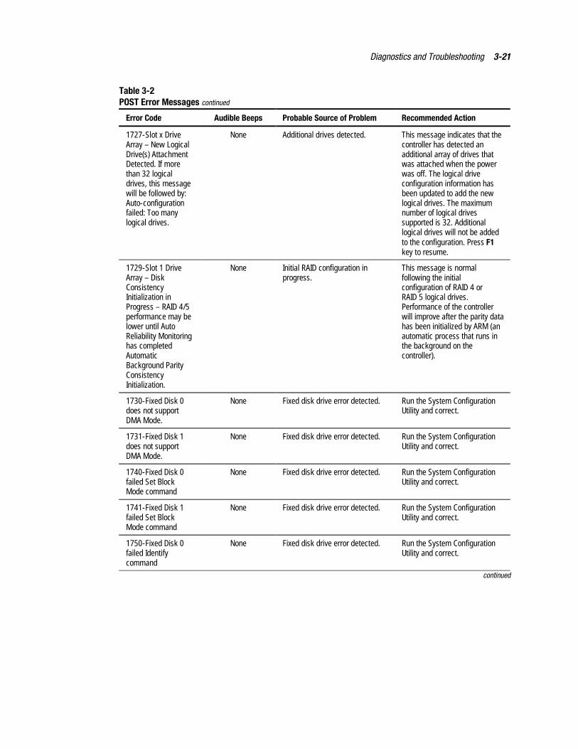
Diagnostics and Troubleshooting 3-21
Table 3-2POST Error Messages continued
Error Code Audible Beeps Probable Source of Problem Recommended Action
1727-Slot x DriveArray – New LogicalDrive(s) AttachmentDetected. If morethan 32 logicaldrives, this messagewill be followed by:Auto-configurationfailed: Too manylogical drives.
None Additional drives detected. This message indicates that thecontroller has detected anadditional array of drives thatwas attached when the powerwas off. The logical driveconfiguration information hasbeen updated to add the newlogical drives. The maximumnumber of logical drivessupported is 32. Additionallogical drives will not be addedto the configuration. Press F1key to resume.
1729-Slot 1 DriveArray – DiskConsistencyInitialization inProgress – RAID 4/5performance may belower until AutoReliability Monitoringhas completedAutomaticBackground ParityConsistencyInitialization.
None Initial RAID configuration inprogress.
This message is normalfollowing the initialconfiguration of RAID 4 orRAID 5 logical drives.Performance of the controllerwill improve after the parity datahas been initialized by ARM (anautomatic process that runs inthe background on thecontroller).
1730-Fixed Disk 0does not supportDMA Mode.
None Fixed disk drive error detected. Run the System ConfigurationUtility and correct.
1731-Fixed Disk 1does not supportDMA Mode.
None Fixed disk drive error detected. Run the System ConfigurationUtility and correct.
1740-Fixed Disk 0failed Set BlockMode command
None Fixed disk drive error detected. Run the System ConfigurationUtility and correct.
1741-Fixed Disk 1failed Set BlockMode command
None Fixed disk drive error detected. Run the System ConfigurationUtility and correct.
1750-Fixed Disk 0failed Identifycommand
None Fixed disk drive error detected. Run the System ConfigurationUtility and correct.
continued
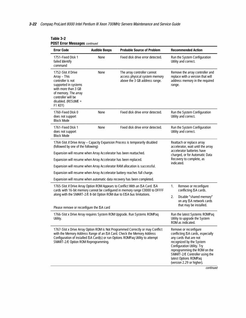
3-22 Compaq ProLiant 8000 Intel Pentium III Xeon 700MHz Servers Maintenance and Service Guide
Table 3-2POST Error Messages continued
Error Code Audible Beeps Probable Source of Problem Recommended Action
1751-Fixed Disk 1failed Identifycommand
None Fixed disk drive error detected. Run the System ConfigurationUtility and correct.
1752-Slot X DriveArray – Thiscontroller is notsupported in systemswith more than 3 GBof memory. The arraycontroller will bedisabled. (RESUME =F1 KEY)
None The array controller cannotaccess physical system memoryabove the 3 GB address range.
Remove the array controller andreplace with a version that willaddress memory in the requiredrange.
1760-Fixed Disk 0does not supportBlock Mode
None Fixed disk drive error detected. Run the System ConfigurationUtility and correct.
1761-Fixed Disk 1does not supportBlock Mode
None Fixed disk drive error detected. Run the System ConfigurationUtility and correct.
1764-Slot X Drive Array – Capacity Expansion Process is temporarily disabled(followed by one of the following)
Expansion will resume when Array Accelerator has been reattached.
Expansion will resume when Array Accelerator has been replaced.
Expansion will resume when Array Accelerator RAM allocation is successful.
Expansion will resume when Array Accelerator battery reaches full charge.
Expansion will resume when automatic data recovery has been completed.
Reattach or replace arrayaccelerator, wait until the arrayaccelerator batteries havecharged, or for Automatic DataRecovery to complete, asindicated.
1765-Slot X Drive Array Option ROM Appears to Conflict With an ISA Card. ISAcards with 16-bit memory cannot be configured in memory range C0000 to DFFFFalong with the SMART-2/E 8-bit Option ROM due to EISA bus limitations.
Please remove or reconfigure the ISA card
1. Remove or reconfigureconflicting ISA cards.
2. Disable “shared memory”on any ISA network cardsthat may be installed.
1766-Slot x Drive Array requires System ROM Upgrade. Run Systems ROMPaqUtility.
Run the latest Systems ROMPaqUtility to upgrade the SystemROM as indicated.
1767-Slot x Drive Array Option ROM is Not Programmed Correctly or may Conflictwith the Memory Address Range of an ISA Card. Check the Memory AddressConfiguration of installed ISA Card(s) or run Options ROMPaq Utility to attemptSMART-2/E Option ROM Reprogramming.
Remove or reconfigureconflicting ISA cards, especiallyany cards that are notrecognized by the SystemConfiguration Utility. Tryreprogramming the ROM on theSMART-2/E Controller using thelatest Options ROMPaq(version 2.29 or higher).
continued
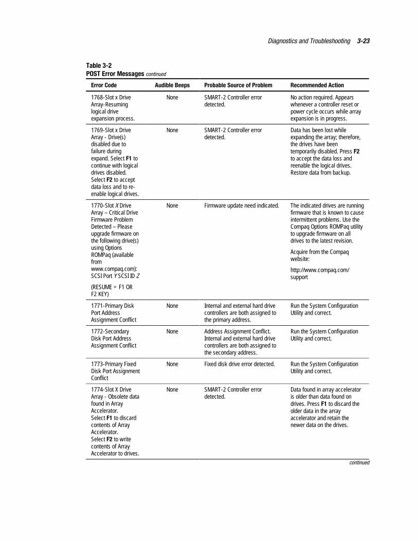
Diagnostics and Troubleshooting 3-23
Table 3-2POST Error Messages continued
Error Code Audible Beeps Probable Source of Problem Recommended Action
1768-Slot x DriveArray-Resuminglogical driveexpansion process.
None SMART-2 Controller errordetected.
No action required. Appearswhenever a controller reset orpower cycle occurs while arrayexpansion is in progress.
1769-Slot x DriveArray - Drive(s)disabled due tofailure duringexpand. Select F1 tocontinue with logicaldrives disabled.Select F2 to acceptdata loss and to re-enable logical drives.
None SMART-2 Controller errordetected.
Data has been lost whileexpanding the array; therefore,the drives have beentemporarily disabled. Press F2to accept the data loss andreenable the logical drives.Restore data from backup.
1770-Slot X DriveArray – Critical DriveFirmware ProblemDetected – Pleaseupgrade firmware onthe following drive(s)using OptionsROMPaq (availablefromwww.compaq.com):SCSI Port Y SCSI ID Z
(RESUME = F1 ORF2 KEY)
None Firmware update need indicated. The indicated drives are runningfirmware that is known to causeintermittent problems. Use theCompaq Options ROMPaq utilityto upgrade firmware on alldrives to the latest revision.
Acquire from the Compaqwebsite:
http://www.compaq.com/support
1771-Primary DiskPort AddressAssignment Conflict
None Internal and external hard drivecontrollers are both assigned tothe primary address.
Run the System ConfigurationUtility and correct.
1772-SecondaryDisk Port AddressAssignment Conflict
None Address Assignment Conflict.Internal and external hard drivecontrollers are both assigned tothe secondary address.
Run the System ConfigurationUtility and correct.
1773-Primary FixedDisk Port AssignmentConflict
None Fixed disk drive error detected. Run the System ConfigurationUtility and correct.
1774-Slot X DriveArray - Obsolete datafound in ArrayAccelerator.Select F1 to discardcontents of ArrayAccelerator.Select F2 to writecontents of ArrayAccelerator to drives.
None SMART-2 Controller errordetected.
Data found in array acceleratoris older than data found ondrives. Press F1 to discard theolder data in the arrayaccelerator and retain thenewer data on the drives.
continued
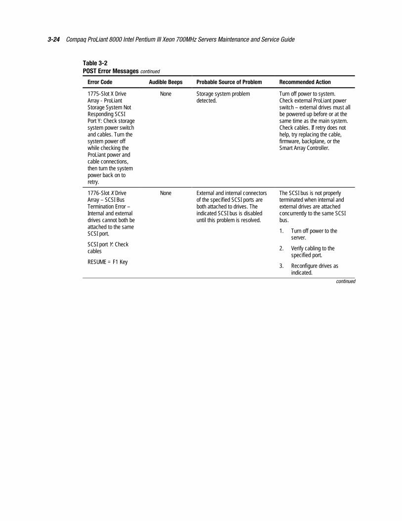
3-24 Compaq ProLiant 8000 Intel Pentium III Xeon 700MHz Servers Maintenance and Service Guide
Table 3-2POST Error Messages continued
Error Code Audible Beeps Probable Source of Problem Recommended Action
1775-Slot X DriveArray - ProLiantStorage System NotResponding SCSIPort Y: Check storagesystem power switchand cables. Turn thesystem power offwhile checking theProLiant power andcable connections,then turn the systempower back on toretry.
None Storage system problemdetected.
Turn off power to system.Check external ProLiant powerswitch – external drives must allbe powered up before or at thesame time as the main system.Check cables. If retry does nothelp, try replacing the cable,firmware, backplane, or theSmart Array Controller.
1776-Slot X DriveArray – SCSI BusTermination Error –Internal and externaldrives cannot both beattached to the sameSCSI port.
SCSI port Y: Checkcables
RESUME = F1 Key
None External and internal connectorsof the specified SCSI ports areboth attached to drives. Theindicated SCSI bus is disableduntil this problem is resolved.
The SCSI bus is not properlyterminated when internal andexternal drives are attachedconcurrently to the same SCSIbus.
1. Turn off power to theserver.
2. Verify cabling to thespecified port.
3. Reconfigure drives asindicated.
continued
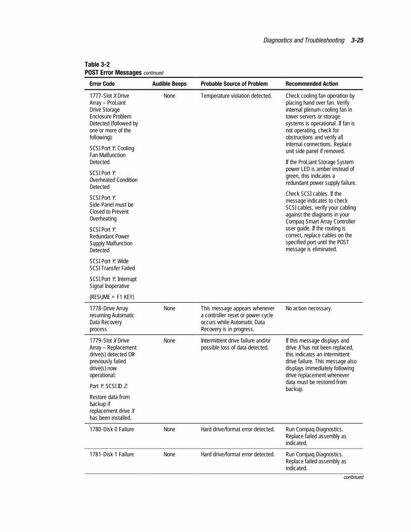
Diagnostics and Troubleshooting 3-25
Table 3-2POST Error Messages continued
Error Code Audible Beeps Probable Source of Problem Recommended Action
1777-Slot X DriveArray – ProLiantDrive StorageEnclosure ProblemDetected (followed byone or more of thefollowing):
SCSI Port Y: CoolingFan MalfunctionDetected
SCSI Port Y:Overheated ConditionDetected
SCSI Port Y:Side-Panel must beClosed to PreventOverheating
SCSI Port Y:Redundant PowerSupply MalfunctionDetected
SCSI Port Y: WideSCSI Transfer Failed
SCSI Port Y: InterruptSignal Inoperative
(RESUME = F1 KEY)
None Temperature violation detected. Check cooling fan operation byplacing hand over fan. Verifyinternal plenum cooling fan intower servers or storagesystems is operational. If fan isnot operating, check forobstructions and verify allinternal connections. Replaceunit side panel if removed.
If the ProLiant Storage Systempower LED is amber instead ofgreen, this indicates aredundant power supply failure.
Check SCSI cables. If themessage indicates to checkSCSI cables, verify your cablingagainst the diagrams in yourCompaq Smart Array Controlleruser guide. If the routing iscorrect, replace cables on thespecified port until the POSTmessage is eliminated.
1778-Drive Arrayresuming AutomaticData Recoveryprocess
None This message appears whenevera controller reset or power cycleoccurs while Automatic DataRecovery is in progress.
No action necessary.
1779-Slot X DriveArray – Replacementdrive(s) detected ORpreviously faileddrive(s) nowoperational:
Port Y: SCSI ID Z:
Restore data frombackup ifreplacement drive Xhas been installed.
None Intermittent drive failure and/orpossible loss of data detected.
If this message displays anddrive X has not been replaced,this indicates an intermittentdrive failure. This message alsodisplays immediately followingdrive replacement wheneverdata must be restored frombackup.
1780-Disk 0 Failure None Hard drive/format error detected. Run Compaq Diagnostics.Replace failed assembly asindicated.
1781-Disk 1 Failure None Hard drive/format error detected. Run Compaq Diagnostics.Replace failed assembly asindicated.
continued
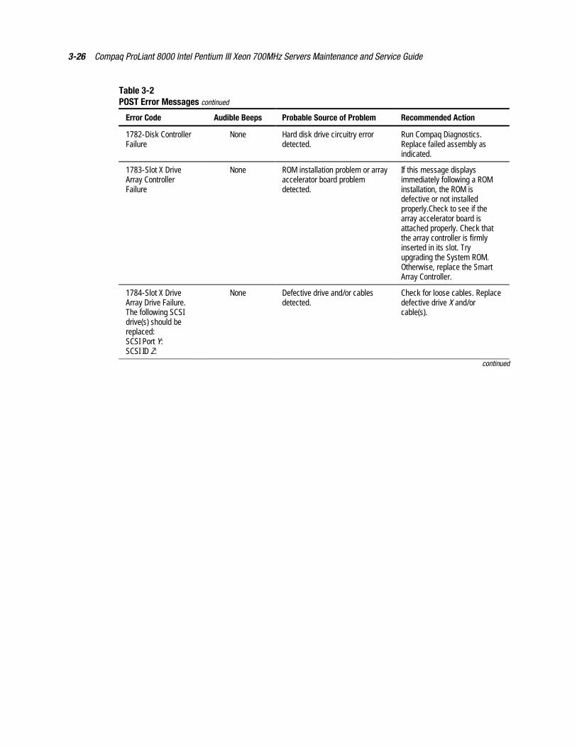
3-26 Compaq ProLiant 8000 Intel Pentium III Xeon 700MHz Servers Maintenance and Service Guide
Table 3-2POST Error Messages continued
Error Code Audible Beeps Probable Source of Problem Recommended Action
1782-Disk ControllerFailure
None Hard disk drive circuitry errordetected.
Run Compaq Diagnostics.Replace failed assembly asindicated.
1783-Slot X DriveArray ControllerFailure
None ROM installation problem or arrayaccelerator board problemdetected.
If this message displaysimmediately following a ROMinstallation, the ROM isdefective or not installedproperly.Check to see if thearray accelerator board isattached properly. Check thatthe array controller is firmlyinserted in its slot. Tryupgrading the System ROM.Otherwise, replace the SmartArray Controller.
1784-Slot X DriveArray Drive Failure.The following SCSIdrive(s) should bereplaced:SCSI Port Y:SCSI ID Z:
None Defective drive and/or cablesdetected.
Check for loose cables. Replacedefective drive X and/orcable(s).
continued
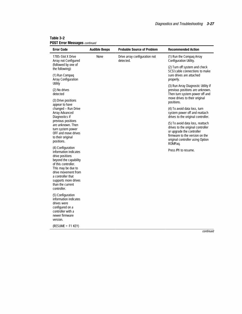
Diagnostics and Troubleshooting 3-27
Table 3-2POST Error Messages continued
Error Code Audible Beeps Probable Source of Problem Recommended Action
1785-Slot X DriveArray not Configured(followed by one ofthe following):
(1) Run CompaqArray ConfigurationUtility
(2) No drivesdetected
(3) Drive positionsappear to havechanged – Run DriveArray AdvancedDiagnostics ifprevious positionsare unknown. Thenturn system powerOFF and move drivesto their originalpositions.
(4) Configurationinformation indicatesdrive positionsbeyond the capabilityof this controller.This may be due todrive movement froma controller thatsupports more drivesthan the currentcontroller.
(5) Configurationinformation indicatesdrives wereconfigured on acontroller with anewer firmwareversion.
(RESUME = F1 KEY)
None Drive array configuration notdetected.
(1) Run the Compaq ArrayConfiguration Utility.
(2) Turn off system and checkSCSI cable connections to makesure drives are attachedproperly.
(3) Run Array Diagnostic Utility ifprevious positions are unknown.Then turn system power off andmove drives to their originalpositions.
(4) To avoid data loss, turnsystem power off and reattachdrives to the original controller.
(5) To avoid data loss, reattachdrives to the original controlleror upgrade the controllerfirmware to the version on theoriginal controller using OptionROMPaq.
Press F1 to resume.
continued
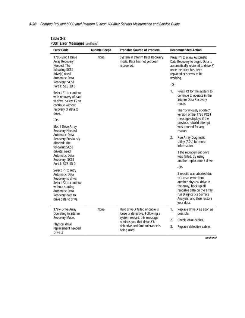
3-28 Compaq ProLiant 8000 Intel Pentium III Xeon 700MHz Servers Maintenance and Service Guide
Table 3-2POST Error Messages continued
Error Code Audible Beeps Probable Source of Problem Recommended Action
1786-Slot 1 DriveArray RecoveryNeeded. Thefollowing SCSIdrive(s) needAutomatic DataRecovery: SCSIPort 1: SCSI ID 0
Select F1 to continuewith recovery of datato drive. Select F2 tocontinue withoutrecovery of data todrive.
-Or-
Slot 1 Drive ArrayRecovery Needed.Automatic DataRecovery PreviouslyAborted! Thefollowing SCSIdrive(s) needAutomatic DataRecovery: SCSIPort 1: SCSI ID 0
Select F1 to retryAutomatic DataRecovery to drive.Select F2 to continuewithout startingAutomatic DataRecovery data todrive data to drive.
None System in Interim Data Recoverymode. Data has not yet beenrecovered.
Press F1 to allow AutomaticData Recovery to begin. Data isautomatically restored to drive Xonce the drive has beenreplaced or seems to beworking.
-Or-
1. Press F2 for the system tocontinue to operate in theInterim Data Recoverymode.
The “previously aborted”version of the 1786 POSTmessage displays if theprevious rebuild attemptwas aborted for anyreason.
2. Run Array DiagnosticUtility (ADU) for moreinformation.
If the replacement drivewas failed, try usinganother replacement drive.
-Or-
If rebuild was aborted dueto a read error fromanother physical drive inthe array, back up allreadable data on the array,run Diagnostics SurfaceAnalysis, and then restoreyour data.
1787-Drive ArrayOperating in InterimRecovery Mode.
Physical drivereplacement needed:Drive X
None Hard drive X failed or cable isloose or defective. Following asystem restart, this messagereminds you that drive X isdefective and fault tolerance isbeing used.
1. Replace drive X as soon aspossible.
2. Check loose cables.
3. Replace defective cables.
continued

Diagnostics and Troubleshooting 3-29
Table 3-2POST Error Messages continued
Error Code Audible Beeps Probable Source of Problem Recommended Action
***1788-Slot X DriveArray ReportsIncorrect DriveReplacement. Thefollowing SCSIdrive(s) should havebeen replaced: SCSIPort Y: SCSI ID Z
The following SCSIdrive(s) wereincorrectly replaced:SCSI Port y:SCSI ID z.
Select F1 to continue– drive array willremain disabled.
Select F2 to resetconfiguration – alldata will be lost.
None Drives are not installed in theiroriginal positions, so the driveshave been disabled. See notebelow.
1. Reinstall the drivescorrectly as indicated.
2. Press F1 to restart thecomputer with the drivearray disabled.
-Or-
Press F2 to use the drivesas configured and lose allthe data on them.
*** The 1788 error message might also be displayed inadvertently due to a bad power cable connection to the drive,noise on the data cable, or a defective SCSI cable. If this message was due to a bad power cable connection, but notincorrect drive replacement, repair the connection and press F2. If the message is not eliminated by pressing F2, runArray Diagnostic Utility (ADU) to resolve.
-Or-
If this message was not due to a bad power cable connection, and no drive replacement took place, this could indicatenoise on the data cable. Check cable for proper routing.
-Or-
If this message is due to a defective SCSI cable, replace the cable.
continued
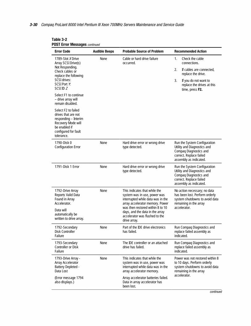
3-30 Compaq ProLiant 8000 Intel Pentium III Xeon 700MHz Servers Maintenance and Service Guide
Table 3-2POST Error Messages continued
Error Code Audible Beeps Probable Source of Problem Recommended Action
1789-Slot X DriveArray SCSI Drive(s)Not Responding.Check cables orreplace the followingSCSI drives:SCSI Port Y:SCSI ID Z
Select F1 to continue– drive array willremain disabled.
Select F2 to faileddrives that are notresponding – InterimRecovery Mode willbe enabled ifconfigured for faulttolerance.
None Cable or hard drive failureoccurred.
1. Check the cableconnections.
2. If cables are connected,replace the drive.
3. If you do not want toreplace the drives at thistime, press F2.
1790-Disk 0Configuration Error
None Hard drive error or wrong drivetype detected.
Run the System ConfigurationUtility and Diagnostics andCompaq Diagnostics andcorrect. Replace failedassembly as indicated.
1791-Disk 1 Error None Hard drive error or wrong drivetype detected.
Run the System ConfigurationUtility and Diagnostics andCompaq Diagnostics andcorrect. Replace failedassembly as indicated.
1792-Drive ArrayReports Valid DataFound in ArrayAccelerator.
Data willautomatically bewritten to drive array.
None This indicates that while thesystem was in use, power wasinterrupted while data was in thearray accelerator memory. Powerwas then restored within 8 to 10days, and the data in the arrayaccelerator was flushed to thedrive array.
No action necessary; no datahas been lost. Perform orderlysystem shutdowns to avoid dataremaining in the arrayaccelerator.
1792-SecondaryDisk ControllerFailure
None Part of the IDE drive electronicshas failed.
Run Compaq Diagnostics andreplace failed assembly asindicated.
1793-SecondaryController or DiskFailure
None The IDE controller or an attacheddrive has failed.
Run Compaq Diagnostics andreplace failed assembly asindicated.
1793-Drive Array -Array AcceleratorBattery Depleted -Data Lost
(Error message 1794also displays.)
None This indicates that while thesystem was in use, power wasinterrupted while data was in thearray accelerator memory.
Array accelerator batteries failed.Data in array accelerator hasbeen lost.
Power was not restored within 8to 10 days. Perform orderlysystem shutdowns to avoid dataremaining in the arrayaccelerator.
continued
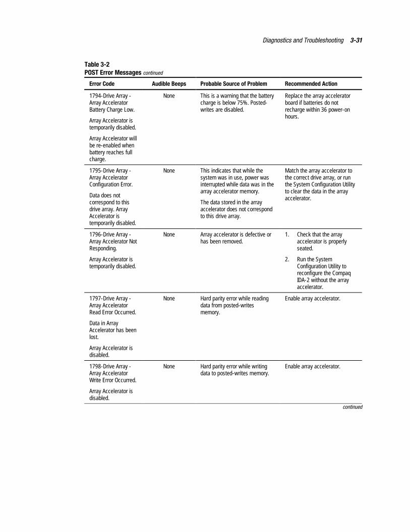
Diagnostics and Troubleshooting 3-31
Table 3-2POST Error Messages continued
Error Code Audible Beeps Probable Source of Problem Recommended Action
1794-Drive Array -Array AcceleratorBattery Charge Low.
Array Accelerator istemporarily disabled.
Array Accelerator willbe re-enabled whenbattery reaches fullcharge.
None This is a warning that the batterycharge is below 75%. Posted-writes are disabled.
Replace the array acceleratorboard if batteries do notrecharge within 36 power-onhours.
1795-Drive Array -Array AcceleratorConfiguration Error.
Data does notcorrespond to thisdrive array. ArrayAccelerator istemporarily disabled.
None This indicates that while thesystem was in use, power wasinterrupted while data was in thearray accelerator memory.
The data stored in the arrayaccelerator does not correspondto this drive array.
Match the array accelerator tothe correct drive array, or runthe System Configuration Utilityto clear the data in the arrayaccelerator.
1796-Drive Array -Array Accelerator NotResponding.
Array Accelerator istemporarily disabled.
None Array accelerator is defective orhas been removed.
1. Check that the arrayaccelerator is properlyseated.
2. Run the SystemConfiguration Utility toreconfigure the CompaqIDA-2 without the arrayaccelerator.
1797-Drive Array -Array AcceleratorRead Error Occurred.
Data in ArrayAccelerator has beenlost.
Array Accelerator isdisabled.
None Hard parity error while readingdata from posted-writesmemory.
Enable array accelerator.
1798-Drive Array -Array AcceleratorWrite Error Occurred.
Array Accelerator isdisabled.
None Hard parity error while writingdata to posted-writes memory.
Enable array accelerator.
continued
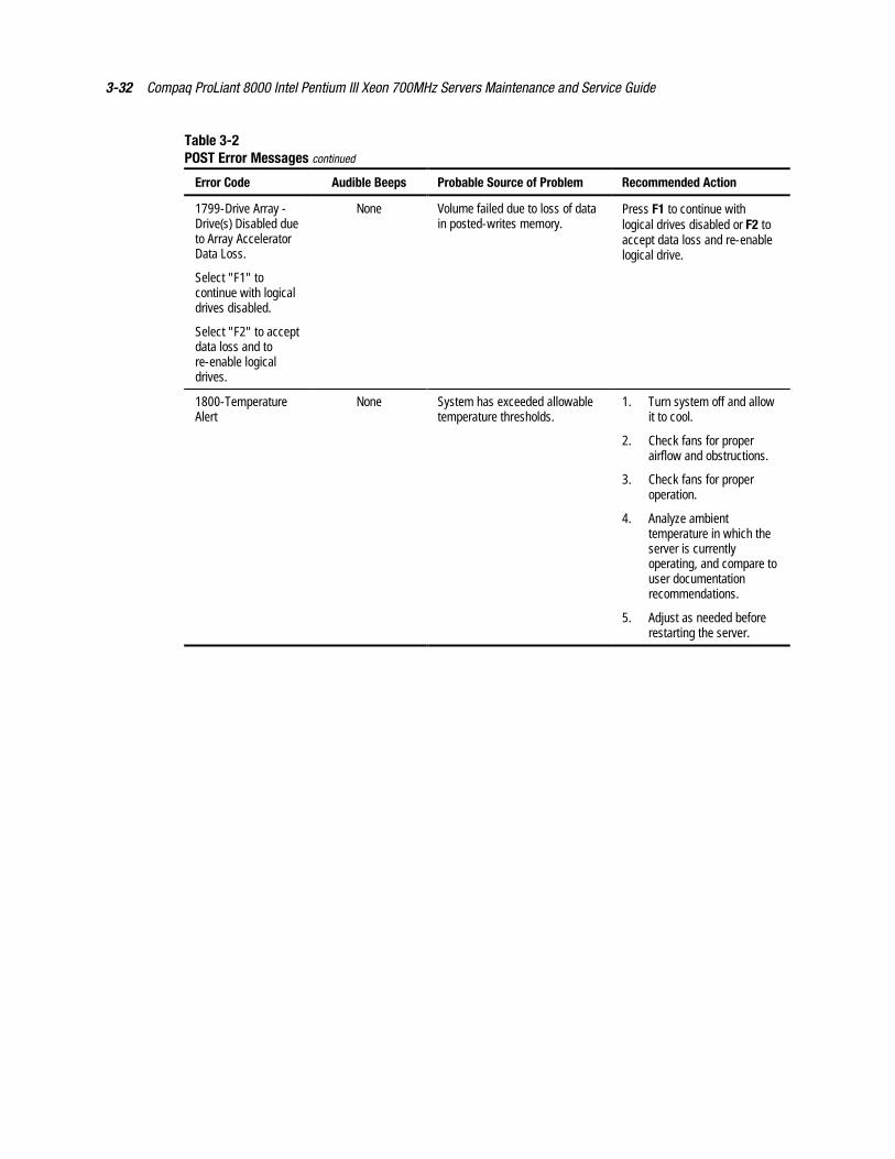
3-32 Compaq ProLiant 8000 Intel Pentium III Xeon 700MHz Servers Maintenance and Service Guide
Table 3-2POST Error Messages continued
Error Code Audible Beeps Probable Source of Problem Recommended Action
1799-Drive Array -Drive(s) Disabled dueto Array AcceleratorData Loss.
Select "F1" tocontinue with logicaldrives disabled.
Select "F2" to acceptdata loss and tore-enable logicaldrives.
None Volume failed due to loss of datain posted-writes memory.
Press F1 to continue withlogical drives disabled or F2 toaccept data loss and re-enablelogical drive.
1800-TemperatureAlert
None System has exceeded allowabletemperature thresholds.
1. Turn system off and allowit to cool.
2. Check fans for properairflow and obstructions.
3. Check fans for properoperation.
4. Analyze ambienttemperature in which theserver is currentlyoperating, and compare touser documentationrecommendations.
5. Adjust as needed beforerestarting the server.
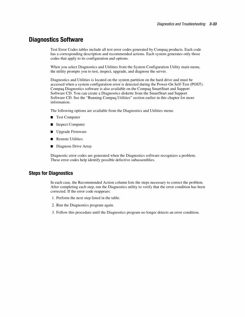
Diagnostics and Troubleshooting 3-33
Diagnostics SoftwareTest Error Codes tables include all test error codes generated by Compaq products. Each codehas a corresponding description and recommended actions. Each system generates only thosecodes that apply to its configuration and options.
When you select Diagnostics and Utilities from the System Configuration Utility main menu,the utility prompts you to test, inspect, upgrade, and diagnose the server.
Diagnostics and Utilities is located on the system partition on the hard drive and must beaccessed when a system configuration error is detected during the Power-On Self-Test (POST).Compaq Diagnostics software is also available on the Compaq SmartStart and SupportSoftware CD. You can create a Diagnostics diskette from the SmartStart and SupportSoftware CD. See the “Running Compaq Utilities” section earlier in this chapter for moreinformation.
The following options are available from the Diagnostics and Utilities menu:
� Test Computer
� Inspect Computer
� Upgrade Firmware
� Remote Utilities
� Diagnose Drive Array
Diagnostic error codes are generated when the Diagnostics software recognizes a problem.These error codes help identify possible defective subassemblies.
Steps for Diagnostics
In each case, the Recommended Action column lists the steps necessary to correct the problem.After completing each step, run the Diagnostics utility to verify that the error condition has beencorrected. If the error code reappears:
1. Perform the next step listed in the table.
2. Run the Diagnostics program again.
3. Follow this procedure until the Diagnostics program no longer detects an error condition.
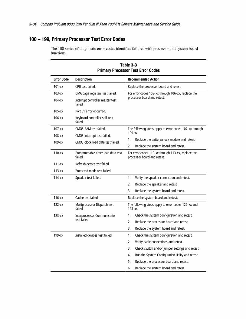
3-34 Compaq ProLiant 8000 Intel Pentium III Xeon 700MHz Servers Maintenance and Service Guide
100 – 199, Primary Processor Test Error Codes
The 100 series of diagnostic error codes identifies failures with processor and system boardfunctions.
Table 3-3Primary Processor Test Error Codes
Error Code Description Recommended Action
101-xx CPU test failed. Replace the processor board and retest.
103-xx DMA page registers test failed.
104-xx Interrupt controller master testfailed.
105-xx Port 61 error occurred.
106-xx Keyboard controller self-testfailed.
For error codes 103-xx through 106-xx, replace theprocessor board and retest.
107-xx CMOS RAM test failed.
108-xx CMOS interrupt test failed.
109-xx CMOS clock load data test failed.
The following steps apply to error codes 107-xx through109-xx.
1. Replace the battery/clock module and retest.
2. Replace the system board and retest.
110-xx Programmable timer load data testfailed.
111-xx Refresh detect test failed.
113-xx Protected mode test failed.
For error codes 110-xx through 113-xx, replace theprocessor board and retest.
114-xx Speaker test failed. 1. Verify the speaker connection and retest.
2. Replace the speaker and retest.
3. Replace the system board and retest.
116-xx Cache test failed. Replace the system board and retest.
122-xx Multiprocessor Dispatch testfailed.
123-xx Interprocessor Communicationtest failed.
The following steps apply to error codes 122-xx and123-xx.
1. Check the system configuration and retest.
2. Replace the processor board and retest.
3. Replace the system board and retest.
199-xx Installed devices test failed. 1. Check the system configuration and retest.
2. Verify cable connections and retest.
3. Check switch and/or jumper settings and retest.
4. Run the System Configuration Utility and retest.
5. Replace the processor board and retest.
6. Replace the system board and retest.
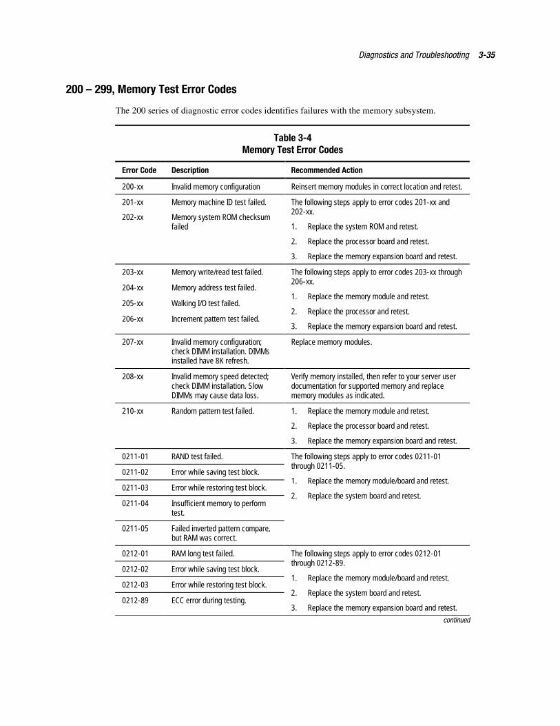
Diagnostics and Troubleshooting 3-35
200 – 299, Memory Test Error Codes
The 200 series of diagnostic error codes identifies failures with the memory subsystem.
Table 3-4Memory Test Error Codes
Error Code Description Recommended Action
200-xx Invalid memory configuration Reinsert memory modules in correct location and retest.
201-xx Memory machine ID test failed.
202-xx Memory system ROM checksumfailed
The following steps apply to error codes 201-xx and202-xx.
1. Replace the system ROM and retest.
2. Replace the processor board and retest.
3. Replace the memory expansion board and retest.
203-xx Memory write/read test failed.
204-xx Memory address test failed.
205-xx Walking I/O test failed.
206-xx Increment pattern test failed.
The following steps apply to error codes 203-xx through206-xx.
1. Replace the memory module and retest.
2. Replace the processor and retest.
3. Replace the memory expansion board and retest.
207-xx Invalid memory configuration;check DIMM installation. DIMMsinstalled have 8K refresh.
Replace memory modules.
208-xx Invalid memory speed detected;check DIMM installation. SlowDIMMs may cause data loss.
Verify memory installed, then refer to your server userdocumentation for supported memory and replacememory modules as indicated.
210-xx Random pattern test failed. 1. Replace the memory module and retest.
2. Replace the processor board and retest.
3. Replace the memory expansion board and retest.
0211-01 RAND test failed.
0211-02 Error while saving test block.
0211-03 Error while restoring test block.
0211-04 Insufficient memory to performtest.
0211-05 Failed inverted pattern compare,but RAM was correct.
The following steps apply to error codes 0211-01through 0211-05.
1. Replace the memory module/board and retest.
2. Replace the system board and retest.
0212-01 RAM long test failed.
0212-02 Error while saving test block.
0212-03 Error while restoring test block.
0212-89 ECC error during testing.
The following steps apply to error codes 0212-01through 0212-89.
1. Replace the memory module/board and retest.
2. Replace the system board and retest.
3. Replace the memory expansion board and retest.
continued
3-36 Compaq ProLiant 8000 Intel Pentium III Xeon 700MHz Servers Maintenance and Service Guide
continued
Error Code Description Recommended Action
0214-01 Data error during test.
0214-89 ECC error during testing.
The following steps apply to error codes 0214-01through 0214-89.
1. Replace the memory module/board and retest.
2. Replace the system board and retest.
215 Nonfunctioning DC-DC converterfor processor X
Replace the Processor Power Module (PPM).
Diagnostics and Troubleshooting 3-37
300 – 399, Keyboard Test Error Codes
The 300 series of diagnostic error codes identifies failures with keyboard and system boardfunctions.
Table 3-5Keyboard Test Error Codes
Error Code Description Recommended Action
301-xx Keyboard short test, 8042 self-testfailed.
302-xx Keyboard long test failed.
303-xx Keyboard LED test, 8042 self-testfailed.
304-xx Keyboard typematic test failed.
The following steps apply to error codes 301-xx through304-xx.
1. Check the keyboard connection. If disconnected,turn off the computer, connect the keyboard, turnon the power, and retest.
2. Replace the keyboard and retest.
3. Replace the system board and retest.
400 – 499, Parallel Printer Test Error Codes
The 400 series of diagnostic error codes identifies failures with parallel printer interface card orsystem board functions.
Table 3-6Parallel Printer Test Error Codes
Error Code Description Recommended Action
401-xx Printer failed or not connected.
402-xx Printer data register failed.
403-xx Printer pattern test failed.
498-xx Printer failed or not connected.
The following steps apply to error codes 401-xx through498-xx.
1. Connect the printer and retest.
2. Check the power to the printer and retest.
3. Install the loopback connector and retest.
4. Check the switch on the serial/parallel interfaceboard (if applicable) and retest.
5. Replace the serial/parallel interface board(if applicable) and retest.
6. Replace the system board and retest.
3-38 Compaq ProLiant 8000 Intel Pentium III Xeon 700MHz Servers Maintenance and Service Guide
500 – 599, Video Display Unit Test Error Codes
The 500 series of diagnostic error codes identifies failures with video or system board functions.
Table 3-7Video Display Unit Test Error Codes
Error Code Description Recommended Action
501-xx Graphics controller test failed.
502-xx Graphics memory test failed.
503-xx Graphics attribute test failed.
504-xx Graphics character set test failed.
505-xx Graphics 80 x 25-mode 9 x 14character cell test failed.
506-xx Graphics 80 x 25-mode 8 x 8character cell test failed.
507-xx Graphics 40 x 25-mode test failed.
508-xx Graphics 320 x 200-mode colorset 0 test failed.
509-xx Graphics 320 x 200-mode colorset 1 test failed.
510-xx Graphics 640 x 200-mode testfailed.
511-xx Graphics screen memory page testfailed.
512-xx Graphics gray scale test failed.
514-xx Graphics white screen test failed.
516-xx Graphics noise pattern test failed.
The following steps apply to error codes 501-xx through516-xx.
1. Replace the monitor and retest.
2. Replace the graphics controller and retest,
-Or-
If the controller is on a separate card, replace thegraphics controller and retest.
3. Replace the system board and retest.
Diagnostics and Troubleshooting 3-39
600 – 699, Diskette Drive Test Error Codes
The 600 series of diagnostic error codes identifies failures with diskette, diskette drive, orsystem board functions.
Table 3-8Diskette Drive Test Error Codes
Error Code Description Recommended Action
600-xx Diskette ID drive types test failed.
601-xx Diskette format failed.
602-xx Diskette read test failed.
603-xx Diskette write/read/compute testfailed.
604-xx Diskette random seek test failed.
605-xx Diskette ID media failed.
606-xx Diskette speed test failed.
607-xx Diskette wrap test failed.
608-xx Diskette write protect test failed.
609-xx Diskette reset controller testfailed.
610-xx Diskette change line test failed.
The following steps apply to error codes 600-xx through610-xx.
1. Replace the diskette and retest.
2. Check and/or replace the diskette power andsignal cables and retest.
3. Replace the diskette drive and retest.
4. Replace the system board and retest.
699-xx Diskette drive/media ID error. 1. Replace the media and retest.
2. Run the System Configuration Utility and retest.
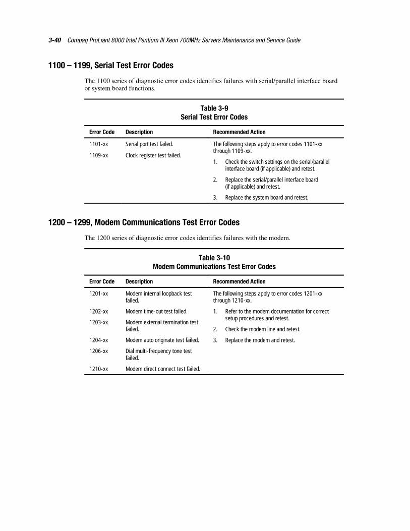
3-40 Compaq ProLiant 8000 Intel Pentium III Xeon 700MHz Servers Maintenance and Service Guide
1100 – 1199, Serial Test Error Codes
The 1100 series of diagnostic error codes identifies failures with serial/parallel interface boardor system board functions.
Table 3-9Serial Test Error Codes
Error Code Description Recommended Action
1101-xx Serial port test failed.
1109-xx Clock register test failed.
The following steps apply to error codes 1101-xxthrough 1109-xx.
1. Check the switch settings on the serial/parallelinterface board (if applicable) and retest.
2. Replace the serial/parallel interface board(if applicable) and retest.
3. Replace the system board and retest.
1200 – 1299, Modem Communications Test Error Codes
The 1200 series of diagnostic error codes identifies failures with the modem.
Table 3-10Modem Communications Test Error Codes
Error Code Description Recommended Action
1201-xx Modem internal loopback testfailed.
1202-xx Modem time-out test failed.
1203-xx Modem external termination testfailed.
1204-xx Modem auto originate test failed.
1206-xx Dial multi-frequency tone testfailed.
1210-xx Modem direct connect test failed.
The following steps apply to error codes 1201-xxthrough 1210-xx.
1. Refer to the modem documentation for correctsetup procedures and retest.
2. Check the modem line and retest.
3. Replace the modem and retest.
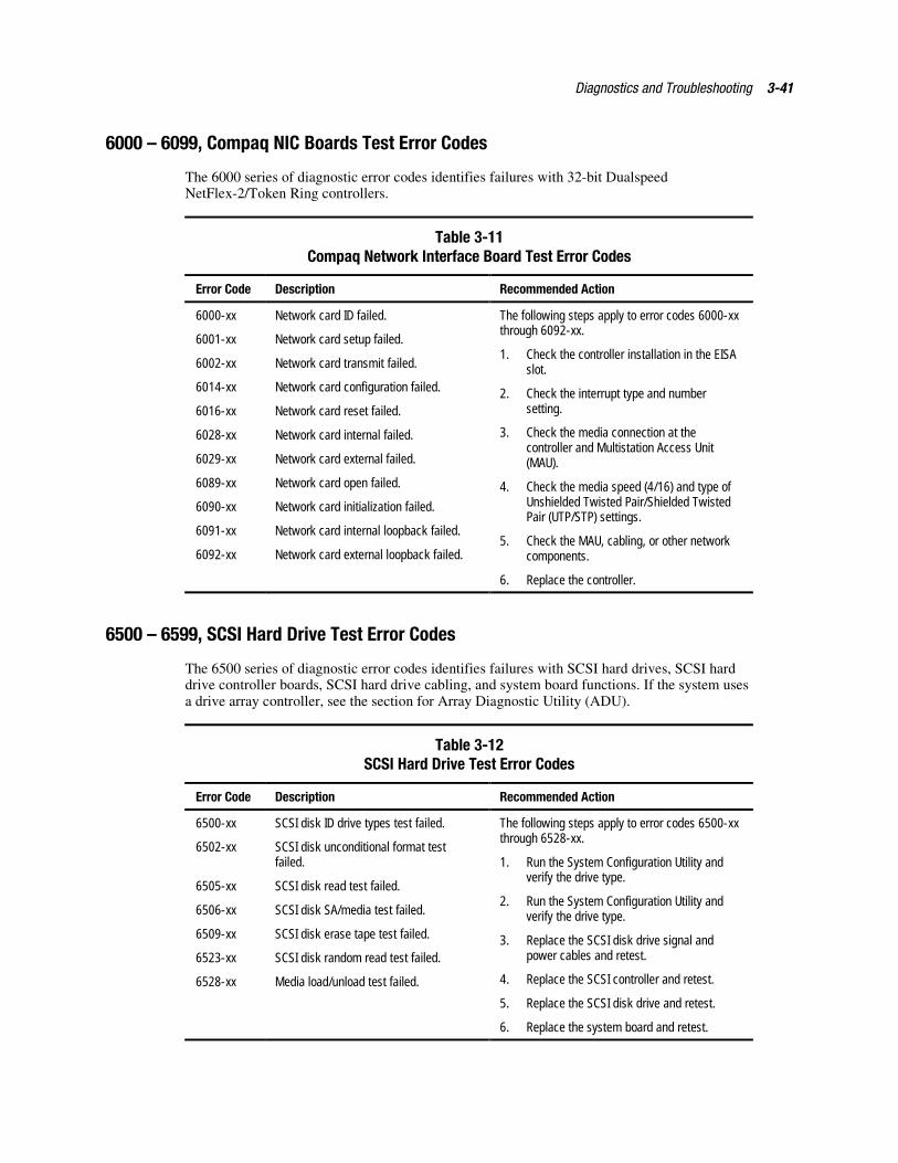
Diagnostics and Troubleshooting 3-41
6000 – 6099, Compaq NIC Boards Test Error Codes
The 6000 series of diagnostic error codes identifies failures with 32-bit DualspeedNetFlex-2/Token Ring controllers.
Table 3-11Compaq Network Interface Board Test Error Codes
Error Code Description Recommended Action
6000-xx Network card ID failed.
6001-xx Network card setup failed.
6002-xx Network card transmit failed.
6014-xx Network card configuration failed.
6016-xx Network card reset failed.
6028-xx Network card internal failed.
6029-xx Network card external failed.
6089-xx Network card open failed.
6090-xx Network card initialization failed.
6091-xx Network card internal loopback failed.
6092-xx Network card external loopback failed.
The following steps apply to error codes 6000-xxthrough 6092-xx.
1. Check the controller installation in the EISAslot.
2. Check the interrupt type and numbersetting.
3. Check the media connection at thecontroller and Multistation Access Unit(MAU).
4. Check the media speed (4/16) and type ofUnshielded Twisted Pair/Shielded TwistedPair (UTP/STP) settings.
5. Check the MAU, cabling, or other networkcomponents.
6. Replace the controller.
6500 – 6599, SCSI Hard Drive Test Error Codes
The 6500 series of diagnostic error codes identifies failures with SCSI hard drives, SCSI harddrive controller boards, SCSI hard drive cabling, and system board functions. If the system usesa drive array controller, see the section for Array Diagnostic Utility (ADU).
Table 3-12SCSI Hard Drive Test Error Codes
Error Code Description Recommended Action
6500-xx SCSI disk ID drive types test failed.
6502-xx SCSI disk unconditional format testfailed.
6505-xx SCSI disk read test failed.
6506-xx SCSI disk SA/media test failed.
6509-xx SCSI disk erase tape test failed.
6523-xx SCSI disk random read test failed.
6528-xx Media load/unload test failed.
The following steps apply to error codes 6500-xxthrough 6528-xx.
1. Run the System Configuration Utility andverify the drive type.
2. Run the System Configuration Utility andverify the drive type.
3. Replace the SCSI disk drive signal andpower cables and retest.
4. Replace the SCSI controller and retest.
5. Replace the SCSI disk drive and retest.
6. Replace the system board and retest.
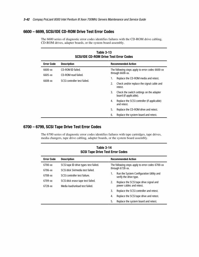
3-42 Compaq ProLiant 8000 Intel Pentium III Xeon 700MHz Servers Maintenance and Service Guide
6600 – 6699, SCSI/IDE CD-ROM Drive Test Error Codes
The 6600 series of diagnostic error codes identifies failures with the CD-ROM drive cabling,CD-ROM drives, adapter boards, or the system board assembly.
Table 3-13SCSI/IDE CD-ROM Drive Test Error Codes
Error Code Description Recommended Action
6600-xx CD-ROM ID failed.
6605-xx CD-ROM read failed.
6608-xx SCSI controller test failed.
The following steps apply to error codes 6600-xxthrough 6608-xx.
1. Replace the CD-ROM media and retest.
2. Check and/or replace the signal cable andretest.
3. Check the switch settings on the adapterboard (if applicable).
4. Replace the SCSI controller (if applicable)and retest.
5. Replace the CD-ROM drive and retest.
6. Replace the system board and retest.
6700 – 6799, SCSI Tape Drive Test Error Codes
The 6700 series of diagnostic error codes identifies failures with tape cartridges, tape drives,media changers, tape drive cabling, adapter boards, or the system board assembly.
Table 3-14SCSI Tape Drive Test Error Codes
Error Code Description Recommended Action
6700-xx SCSI tape ID drive types test failed.
6706-xx SCSI disk SA/media test failed.
6708-xx SCSI controller test failure.
6709-xx SCSI disk erase tape test failed.
6728-xx Media load/unload test failed.
The following steps apply to error codes 6700-xxthrough 6728-xx.
1. Run the System Configuration Utility andverify the drive type.
2. Replace the SCSI tape drive signal andpower cables and retest.
3. Replace the SCSI controller and retest.
4. Replace the SCSI tape drive and retest.
5. Replace the system board and retest.
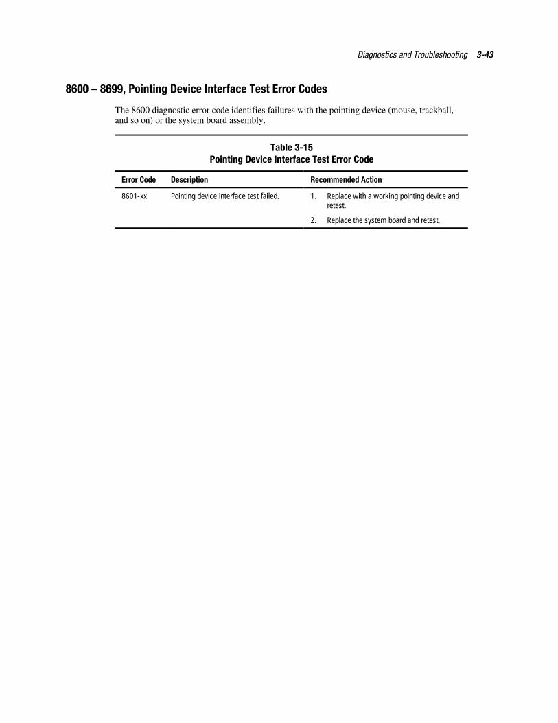
Diagnostics and Troubleshooting 3-43
8600 – 8699, Pointing Device Interface Test Error Codes
The 8600 diagnostic error code identifies failures with the pointing device (mouse, trackball,and so on) or the system board assembly.
Table 3-15Pointing Device Interface Test Error Code
Error Code Description Recommended Action
8601-xx Pointing device interface test failed. 1. Replace with a working pointing device andretest.
2. Replace the system board and retest.
3-44 Compaq ProLiant 8000 Intel Pentium III Xeon 700MHz Servers Maintenance and Service Guide
Array Diagnostic UtilityArray Diagnostic Utility (ADU) is a Windows-based software tool designed to run on allCompaq servers that support Compaq array controllers and are running SmartStart 4.10 or later.The two main functions of ADU are to collect all possible information about array controllers inthe system and to generate a list of detected problems. The error messages and codes listedinclude all codes generated by Compaq products. The system generates only codes applicable tothe configuration and options in the server.
ADU works by issuing multiple commands to the array controllers to determine if a problemexists. This data can then be saved to a file. In severe situations, this file can be sent to Compaqfor analysis. In most cases, ADU provides enough information to initiate problem resolutionimmediately.
NOTE: ADU does not write to the drives, destroy data, or change or remove configuration information.
Starting ADU 1. Insert the SmartStart and Support Software CD into the CD-ROM drive.
2. Reboot the system from the SmartStart and Support Software CD.
3. Select Array Diagnostic Utility (ADU) from the System Utilities menu.
A “Please Wait” panel displays, indicating that ADU is identifying the system parameters.ADU gathers information from all of the array controllers in the system. The time it takesto gather this information depends on the size of the system. When the informationgathering process is complete, ADU displays the main screen or a panel indicating anyproblems detected.
CAUTION: Do not cycle the power during this process. ADU must perform low-level operationsthat, if interrupted, could cause the controller to revert to a previous level of firmware if thefirmware was soft-upgraded.
4. To generate an ADU report, select File then Save Data from the Command menu.
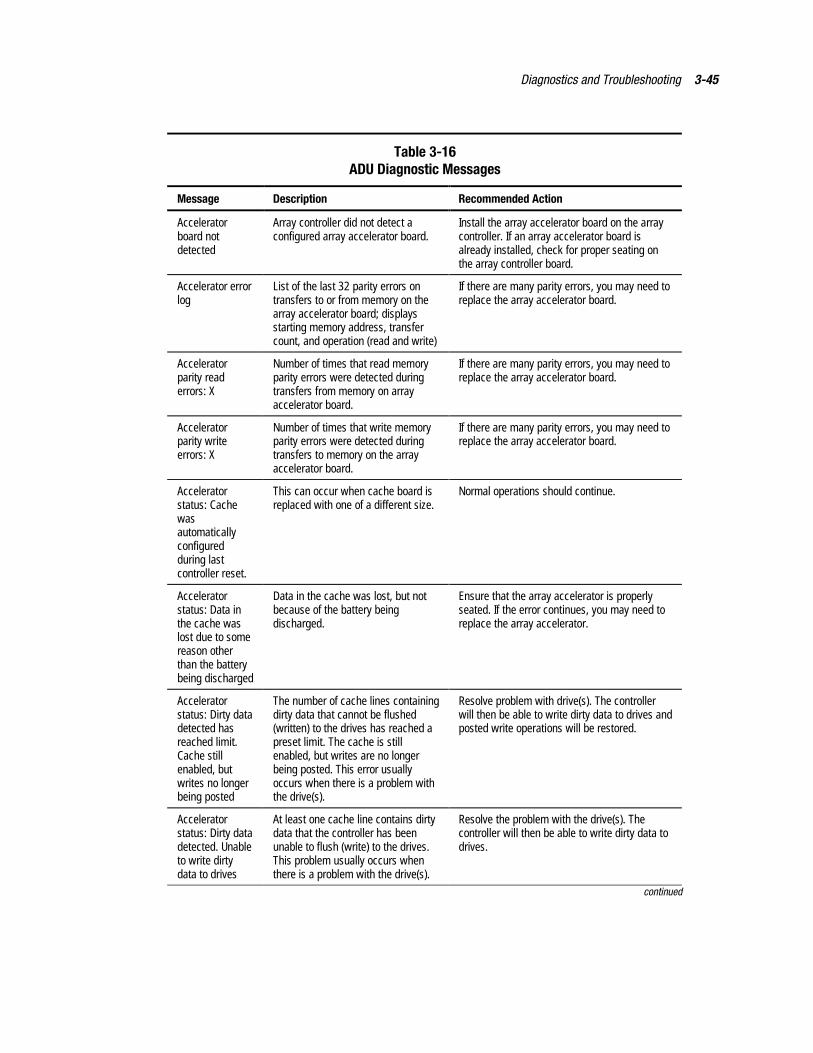
Diagnostics and Troubleshooting 3-45
Table 3-16ADU Diagnostic Messages
Message Description Recommended Action
Acceleratorboard notdetected
Array controller did not detect aconfigured array accelerator board.
Install the array accelerator board on the arraycontroller. If an array accelerator board isalready installed, check for proper seating onthe array controller board.
Accelerator errorlog
List of the last 32 parity errors ontransfers to or from memory on thearray accelerator board; displaysstarting memory address, transfercount, and operation (read and write)
If there are many parity errors, you may need toreplace the array accelerator board.
Acceleratorparity readerrors: X
Number of times that read memoryparity errors were detected duringtransfers from memory on arrayaccelerator board.
If there are many parity errors, you may need toreplace the array accelerator board.
Acceleratorparity writeerrors: X
Number of times that write memoryparity errors were detected duringtransfers to memory on the arrayaccelerator board.
If there are many parity errors, you may need toreplace the array accelerator board.
Acceleratorstatus: Cachewasautomaticallyconfiguredduring lastcontroller reset.
This can occur when cache board isreplaced with one of a different size.
Normal operations should continue.
Acceleratorstatus: Data inthe cache waslost due to somereason otherthan the batterybeing discharged
Data in the cache was lost, but notbecause of the battery beingdischarged.
Ensure that the array accelerator is properlyseated. If the error continues, you may need toreplace the array accelerator.
Acceleratorstatus: Dirty datadetected hasreached limit.Cache stillenabled, butwrites no longerbeing posted
The number of cache lines containingdirty data that cannot be flushed(written) to the drives has reached apreset limit. The cache is stillenabled, but writes are no longerbeing posted. This error usuallyoccurs when there is a problem withthe drive(s).
Resolve problem with drive(s). The controllerwill then be able to write dirty data to drives andposted write operations will be restored.
Acceleratorstatus: Dirty datadetected. Unableto write dirtydata to drives
At least one cache line contains dirtydata that the controller has beenunable to flush (write) to the drives.This problem usually occurs whenthere is a problem with the drive(s).
Resolve the problem with the drive(s). Thecontroller will then be able to write dirty data todrives.
continued
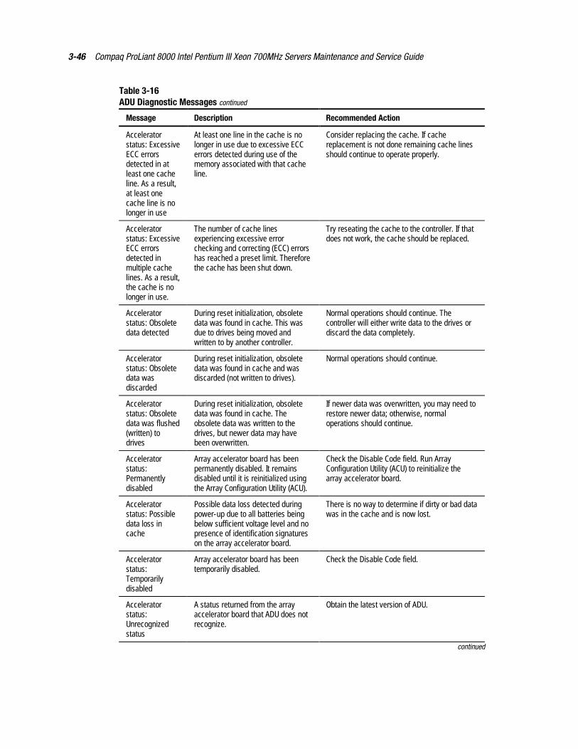
3-46 Compaq ProLiant 8000 Intel Pentium III Xeon 700MHz Servers Maintenance and Service Guide
Table 3-16ADU Diagnostic Messages continued
Message Description Recommended Action
Acceleratorstatus: ExcessiveECC errorsdetected in atleast one cacheline. As a result,at least onecache line is nolonger in use
At least one line in the cache is nolonger in use due to excessive ECCerrors detected during use of thememory associated with that cacheline.
Consider replacing the cache. If cachereplacement is not done remaining cache linesshould continue to operate properly.
Acceleratorstatus: ExcessiveECC errorsdetected inmultiple cachelines. As a result,the cache is nolonger in use.
The number of cache linesexperiencing excessive errorchecking and correcting (ECC) errorshas reached a preset limit. Thereforethe cache has been shut down.
Try reseating the cache to the controller. If thatdoes not work, the cache should be replaced.
Acceleratorstatus: Obsoletedata detected
During reset initialization, obsoletedata was found in cache. This wasdue to drives being moved andwritten to by another controller.
Normal operations should continue. Thecontroller will either write data to the drives ordiscard the data completely.
Acceleratorstatus: Obsoletedata wasdiscarded
During reset initialization, obsoletedata was found in cache and wasdiscarded (not written to drives).
Normal operations should continue.
Acceleratorstatus: Obsoletedata was flushed(written) todrives
During reset initialization, obsoletedata was found in cache. Theobsolete data was written to thedrives, but newer data may havebeen overwritten.
If newer data was overwritten, you may need torestore newer data; otherwise, normaloperations should continue.
Acceleratorstatus:Permanentlydisabled
Array accelerator board has beenpermanently disabled. It remainsdisabled until it is reinitialized usingthe Array Configuration Utility (ACU).
Check the Disable Code field. Run ArrayConfiguration Utility (ACU) to reinitialize thearray accelerator board.
Acceleratorstatus: Possibledata loss incache
Possible data loss detected duringpower-up due to all batteries beingbelow sufficient voltage level and nopresence of identification signatureson the array accelerator board.
There is no way to determine if dirty or bad datawas in the cache and is now lost.
Acceleratorstatus:Temporarilydisabled
Array accelerator board has beentemporarily disabled.
Check the Disable Code field.
Acceleratorstatus:Unrecognizedstatus
A status returned from the arrayaccelerator board that ADU does notrecognize.
Obtain the latest version of ADU.
continued
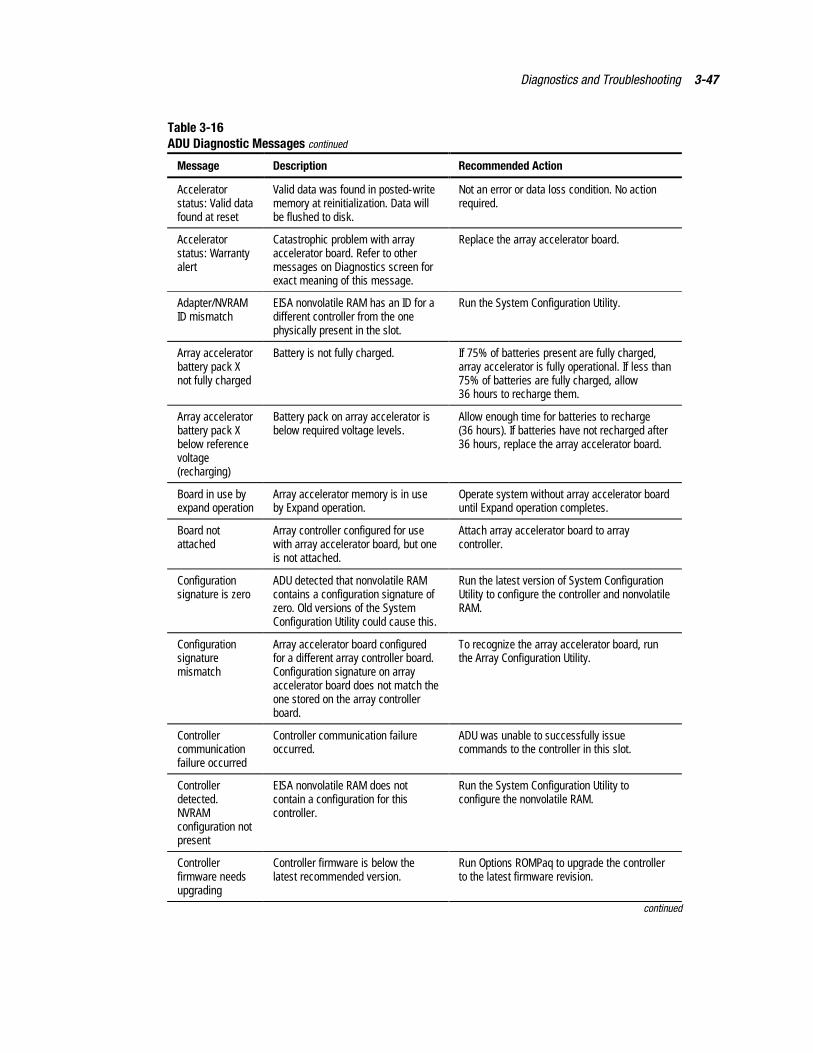
Diagnostics and Troubleshooting 3-47
Table 3-16ADU Diagnostic Messages continued
Message Description Recommended Action
Acceleratorstatus: Valid datafound at reset
Valid data was found in posted-writememory at reinitialization. Data willbe flushed to disk.
Not an error or data loss condition. No actionrequired.
Acceleratorstatus: Warrantyalert
Catastrophic problem with arrayaccelerator board. Refer to othermessages on Diagnostics screen forexact meaning of this message.
Replace the array accelerator board.
Adapter/NVRAMID mismatch
EISA nonvolatile RAM has an ID for adifferent controller from the onephysically present in the slot.
Run the System Configuration Utility.
Array acceleratorbattery pack Xnot fully charged
Battery is not fully charged. If 75% of batteries present are fully charged,array accelerator is fully operational. If less than75% of batteries are fully charged, allow36 hours to recharge them.
Array acceleratorbattery pack Xbelow referencevoltage(recharging)
Battery pack on array accelerator isbelow required voltage levels.
Allow enough time for batteries to recharge(36 hours). If batteries have not recharged after36 hours, replace the array accelerator board.
Board in use byexpand operation
Array accelerator memory is in useby Expand operation.
Operate system without array accelerator boarduntil Expand operation completes.
Board notattached
Array controller configured for usewith array accelerator board, but oneis not attached.
Attach array accelerator board to arraycontroller.
Configurationsignature is zero
ADU detected that nonvolatile RAMcontains a configuration signature ofzero. Old versions of the SystemConfiguration Utility could cause this.
Run the latest version of System ConfigurationUtility to configure the controller and nonvolatileRAM.
Configurationsignaturemismatch
Array accelerator board configuredfor a different array controller board.Configuration signature on arrayaccelerator board does not match theone stored on the array controllerboard.
To recognize the array accelerator board, runthe Array Configuration Utility.
Controllercommunicationfailure occurred
Controller communication failureoccurred.
ADU was unable to successfully issuecommands to the controller in this slot.
Controllerdetected.NVRAMconfiguration notpresent
EISA nonvolatile RAM does notcontain a configuration for thiscontroller.
Run the System Configuration Utility toconfigure the nonvolatile RAM.
Controllerfirmware needsupgrading
Controller firmware is below thelatest recommended version.
Run Options ROMPaq to upgrade the controllerto the latest firmware revision.
continued
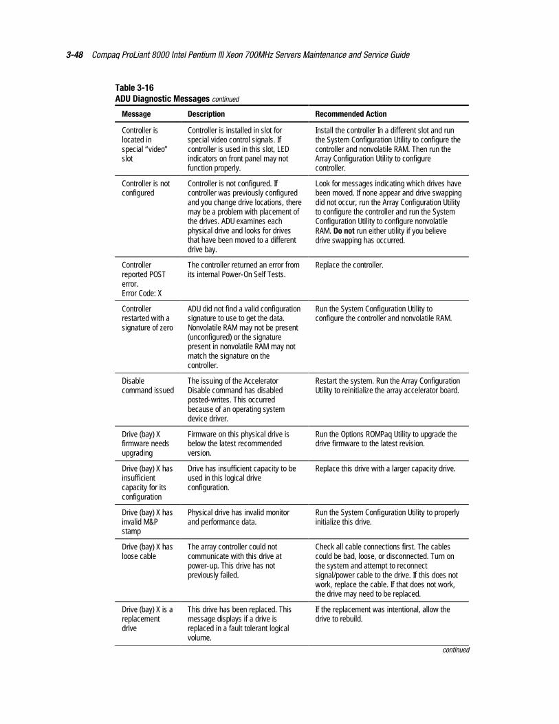
3-48 Compaq ProLiant 8000 Intel Pentium III Xeon 700MHz Servers Maintenance and Service Guide
Table 3-16ADU Diagnostic Messages continued
Message Description Recommended Action
Controller islocated inspecial “video”slot
Controller is installed in slot forspecial video control signals. Ifcontroller is used in this slot, LEDindicators on front panel may notfunction properly.
Install the controller In a different slot and runthe System Configuration Utility to configure thecontroller and nonvolatile RAM. Then run theArray Configuration Utility to configurecontroller.
Controller is notconfigured
Controller is not configured. Ifcontroller was previously configuredand you change drive locations, theremay be a problem with placement ofthe drives. ADU examines eachphysical drive and looks for drivesthat have been moved to a differentdrive bay.
Look for messages indicating which drives havebeen moved. If none appear and drive swappingdid not occur, run the Array Configuration Utilityto configure the controller and run the SystemConfiguration Utility to configure nonvolatileRAM. Do not run either utility if you believedrive swapping has occurred.
Controllerreported POSTerror.Error Code: X
The controller returned an error fromits internal Power-On Self Tests.
Replace the controller.
Controllerrestarted with asignature of zero
ADU did not find a valid configurationsignature to use to get the data.Nonvolatile RAM may not be present(unconfigured) or the signaturepresent in nonvolatile RAM may notmatch the signature on thecontroller.
Run the System Configuration Utility toconfigure the controller and nonvolatile RAM.
Disablecommand issued
The issuing of the AcceleratorDisable command has disabledposted-writes. This occurredbecause of an operating systemdevice driver.
Restart the system. Run the Array ConfigurationUtility to reinitialize the array accelerator board.
Drive (bay) Xfirmware needsupgrading
Firmware on this physical drive isbelow the latest recommendedversion.
Run the Options ROMPaq Utility to upgrade thedrive firmware to the latest revision.
Drive (bay) X hasinsufficientcapacity for itsconfiguration
Drive has insufficient capacity to beused in this logical driveconfiguration.
Replace this drive with a larger capacity drive.
Drive (bay) X hasinvalid M&Pstamp
Physical drive has invalid monitorand performance data.
Run the System Configuration Utility to properlyinitialize this drive.
Drive (bay) X hasloose cable
The array controller could notcommunicate with this drive atpower-up. This drive has notpreviously failed.
Check all cable connections first. The cablescould be bad, loose, or disconnected. Turn onthe system and attempt to reconnectsignal/power cable to the drive. If this does notwork, replace the cable. If that does not work,the drive may need to be replaced.
Drive (bay) X is areplacementdrive
This drive has been replaced. Thismessage displays if a drive isreplaced in a fault tolerant logicalvolume.
If the replacement was intentional, allow thedrive to rebuild.
continued
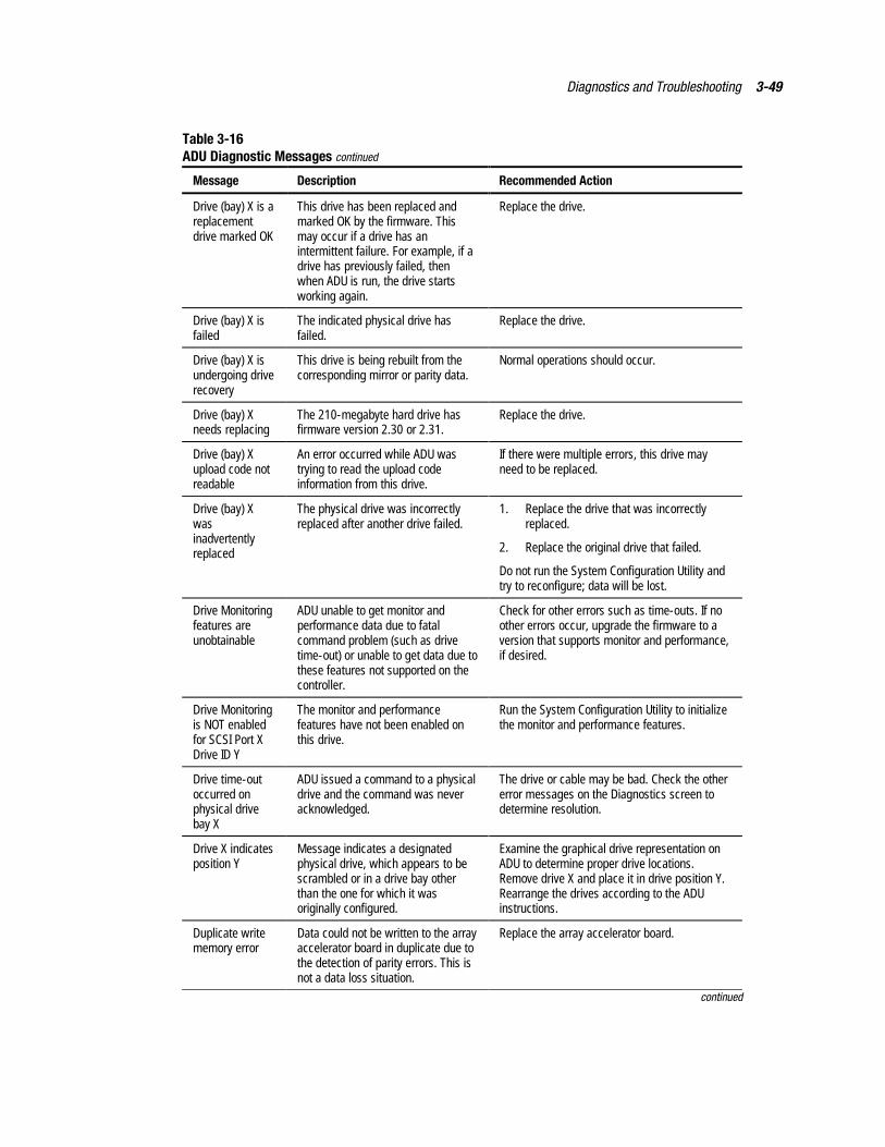
Diagnostics and Troubleshooting 3-49
Table 3-16ADU Diagnostic Messages continued
Message Description Recommended Action
Drive (bay) X is areplacementdrive marked OK
This drive has been replaced andmarked OK by the firmware. Thismay occur if a drive has anintermittent failure. For example, if adrive has previously failed, thenwhen ADU is run, the drive startsworking again.
Replace the drive.
Drive (bay) X isfailed
The indicated physical drive hasfailed.
Replace the drive.
Drive (bay) X isundergoing driverecovery
This drive is being rebuilt from thecorresponding mirror or parity data.
Normal operations should occur.
Drive (bay) Xneeds replacing
The 210-megabyte hard drive hasfirmware version 2.30 or 2.31.
Replace the drive.
Drive (bay) Xupload code notreadable
An error occurred while ADU wastrying to read the upload codeinformation from this drive.
If there were multiple errors, this drive mayneed to be replaced.
Drive (bay) Xwasinadvertentlyreplaced
The physical drive was incorrectlyreplaced after another drive failed.
1. Replace the drive that was incorrectlyreplaced.
2. Replace the original drive that failed.
Do not run the System Configuration Utility andtry to reconfigure; data will be lost.
Drive Monitoringfeatures areunobtainable
ADU unable to get monitor andperformance data due to fatalcommand problem (such as drivetime-out) or unable to get data due tothese features not supported on thecontroller.
Check for other errors such as time-outs. If noother errors occur, upgrade the firmware to aversion that supports monitor and performance,if desired.
Drive Monitoringis NOT enabledfor SCSI Port XDrive ID Y
The monitor and performancefeatures have not been enabled onthis drive.
Run the System Configuration Utility to initializethe monitor and performance features.
Drive time-outoccurred onphysical drivebay X
ADU issued a command to a physicaldrive and the command was neveracknowledged.
The drive or cable may be bad. Check the othererror messages on the Diagnostics screen todetermine resolution.
Drive X indicatesposition Y
Message indicates a designatedphysical drive, which appears to bescrambled or in a drive bay otherthan the one for which it wasoriginally configured.
Examine the graphical drive representation onADU to determine proper drive locations.Remove drive X and place it in drive position Y.Rearrange the drives according to the ADUinstructions.
Duplicate writememory error
Data could not be written to the arrayaccelerator board in duplicate due tothe detection of parity errors. This isnot a data loss situation.
Replace the array accelerator board.
continued
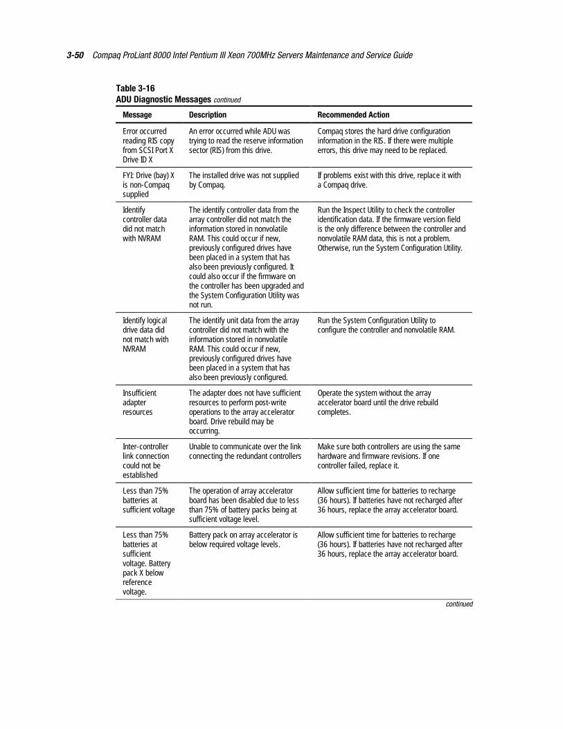
3-50 Compaq ProLiant 8000 Intel Pentium III Xeon 700MHz Servers Maintenance and Service Guide
Table 3-16ADU Diagnostic Messages continued
Message Description Recommended Action
Error occurredreading RIS copyfrom SCSI Port XDrive ID X
An error occurred while ADU wastrying to read the reserve informationsector (RIS) from this drive.
Compaq stores the hard drive configurationinformation in the RIS. If there were multipleerrors, this drive may need to be replaced.
FYI: Drive (bay) Xis non-Compaqsupplied
The installed drive was not suppliedby Compaq.
If problems exist with this drive, replace it witha Compaq drive.
Identifycontroller datadid not matchwith NVRAM
The identify controller data from thearray controller did not match theinformation stored in nonvolatileRAM. This could occur if new,previously configured drives havebeen placed in a system that hasalso been previously configured. Itcould also occur if the firmware onthe controller has been upgraded andthe System Configuration Utility wasnot run.
Run the Inspect Utility to check the controlleridentification data. If the firmware version fieldis the only difference between the controller andnonvolatile RAM data, this is not a problem.Otherwise, run the System Configuration Utility.
Identify logicaldrive data didnot match withNVRAM
The identify unit data from the arraycontroller did not match with theinformation stored in nonvolatileRAM. This could occur if new,previously configured drives havebeen placed in a system that hasalso been previously configured.
Run the System Configuration Utility toconfigure the controller and nonvolatile RAM.
Insufficientadapterresources
The adapter does not have sufficientresources to perform post-writeoperations to the array acceleratorboard. Drive rebuild may beoccurring.
Operate the system without the arrayaccelerator board until the drive rebuildcompletes.
Inter-controllerlink connectioncould not beestablished
Unable to communicate over the linkconnecting the redundant controllers
Make sure both controllers are using the samehardware and firmware revisions. If onecontroller failed, replace it.
Less than 75%batteries atsufficient voltage
The operation of array acceleratorboard has been disabled due to lessthan 75% of battery packs being atsufficient voltage level.
Allow sufficient time for batteries to recharge(36 hours). If batteries have not recharged after36 hours, replace the array accelerator board.
Less than 75%batteries atsufficientvoltage. Batterypack X belowreferencevoltage.
Battery pack on array accelerator isbelow required voltage levels.
Allow sufficient time for batteries to recharge(36 hours). If batteries have not recharged after36 hours, replace the array accelerator board.
continued
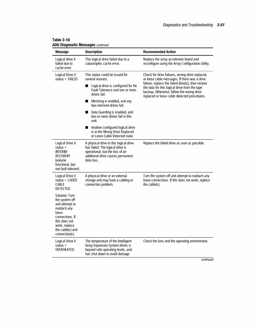
Diagnostics and Troubleshooting 3-51
Table 3-16ADU Diagnostic Messages continued
Message Description Recommended Action
Logical drive Xfailed due tocache error
This logical drive failed due to acatastrophic cache error.
Replace the array accelerator board andreconfigure using the Array Configuration Utility.
Logical Drive Xstatus = FAILED
This status could be issued forseveral reasons.
� Logical drive is configured for NoFault Tolerance and one or moredrives fail.
� Mirroring is enabled, and anytwo mirrored drives fail.
� Data Guarding is enabled, andtwo or more drives fail in thisunit.
� Another configured logical driveis in the Wrong Drive Replacedor Loose Cable Detected state.
Check for drive failures, wrong drive replaced,or loose cable messages. If there was a drivefailure, replace the failed drive(s), then restorethe data for this logical drive from the tapebackup. Otherwise, follow the wrong drivereplaced or loose cable detected procedures.
Logical Drive Xstatus =INTERIMRECOVERY(volumefunctional, butnot fault tolerant)
A physical drive in this logical drivehas failed. The logical drive isoperational, but the loss of anadditional drive causes permanentdata loss.
Replace the failed drive as soon as possible.
Logical Drive Xstatus = LOOSECABLEDETECTED
Solution: Turnthe system offand attempt toreattach anylooseconnections. Ifthis does notwork, replacethe cable(s) andconnection(s).
A physical drive or an externalstorage unit may have a cabling orconnection problem.
Turn the system off and attempt to reattach anyloose connections. If this does not work, replacethe cable(s).
Logical Drive Xstatus =OVERHEATED
The temperature of the IntelligentArray Expansion System drives isbeyond safe operating levels, andhas shut down to avoid damage.
Check the fans and the operating environment.
continued
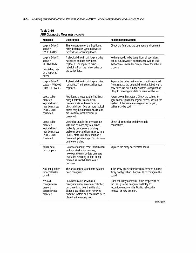
3-52 Compaq ProLiant 8000 Intel Pentium III Xeon 700MHz Servers Maintenance and Service Guide
Table 3-16ADU Diagnostic Messages continued
Message Description Recommended Action
Logical Drive Xstatus =OVERHEATING
The temperature of the IntelligentArray Expansion System drives isbeyond safe operating levels.
Check the fans and the operating environment.
Logical Drive Xstatus =RECOVERING
(rebuilding dataon a replaceddrive)
A physical drive in this logical drivehas failed and has now beenreplaced. The replaced drive isrebuilding from the mirror drive orthe parity data.
Nothing needs to be done. Normal operationscan occur, however, performance will be lessthat optimal until after completion of the rebuildprocess.
Logical Drive Xstatus = WRONGDRIVE REPLACED
A physical drive in this logical drivehas failed. The incorrect drive wasreplaced.
Replace the drive that was incorrectly replaced.Then, replace the original drive that failed with anew drive. Do not run the System ConfigurationUtility to reconfigure; data on drive will be lost.
Loose cabledetected -logical drivesmay be markedFAILED untilcorrected
ADU found a loose cable. The SmartArray Controller is unable tocommunicate with one or morephysical drives. One or more logicaldrives may be marked FAILED, andare unusable until problem iscorrected.
Power down the system. Check the cables fortight connection to the logical drives. Restart thesystem. If the same message occurs again,cables may be bad.
Loose cabledetected -logical drivesmay be markedFAILED untilcorrected
Controller unable to communicatewith one or more physical drives,probably because of a cablingproblem. Logical drives may be in aFAILED state until the condition iscorrected, preventing access to dataon the controller.
Check all controller and drive cableconnections.
Mirror datamiscompare
Data was found at reset initializationin the posted-write memory;however, the mirror data comparetest failed resulting in data beingmarked as invalid. Data loss ispossible.
Replace the array accelerator board.
No configurationfor acceleratorboard
The array accelerator board has notbeen configured.
If the array accelerator board is present, run theArray Configuration Utility (ACU) to configure theboard.
NVRAMconfigurationpresent,controller notdetected
EISA nonvolatile RAM has aconfiguration for an array controller,but there is no board in this slot.Either a board has been removedfrom the system or a board has beenplaced in the wrong slot.
Place the array controller in the proper slot orrun the System Configuration Utility toreconfigure nonvolatile RAM to reflect theremoval or new position.
continued
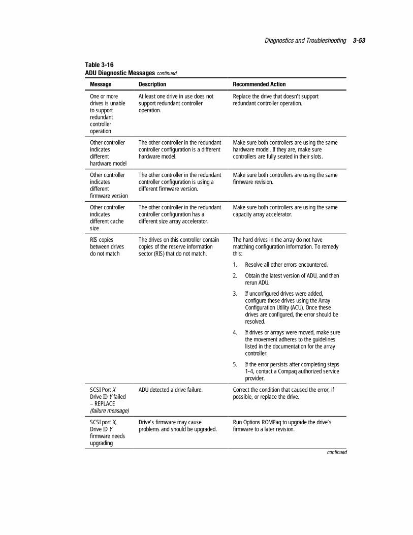
Diagnostics and Troubleshooting 3-53
Table 3-16ADU Diagnostic Messages continued
Message Description Recommended Action
One or moredrives is unableto supportredundantcontrolleroperation
At least one drive in use does notsupport redundant controlleroperation.
Replace the drive that doesn’t supportredundant controller operation.
Other controllerindicatesdifferenthardware model
The other controller in the redundantcontroller configuration is a differenthardware model.
Make sure both controllers are using the samehardware model. If they are, make surecontrollers are fully seated in their slots.
Other controllerindicatesdifferentfirmware version
The other controller in the redundantcontroller configuration is using adifferent firmware version.
Make sure both controllers are using the samefirmware revision.
Other controllerindicatesdifferent cachesize
The other controller in the redundantcontroller configuration has adifferent size array accelerator.
Make sure both controllers are using the samecapacity array accelerator.
RIS copiesbetween drivesdo not match
The drives on this controller containcopies of the reserve informationsector (RIS) that do not match.
The hard drives in the array do not havematching configuration information. To remedythis:
1. Resolve all other errors encountered.
2. Obtain the latest version of ADU, and thenrerun ADU.
3. If unconfigured drives were added,configure these drives using the ArrayConfiguration Utility (ACU). Once thesedrives are configured, the error should beresolved.
4. If drives or arrays were moved, make surethe movement adheres to the guidelineslisted in the documentation for the arraycontroller.
5. If the error persists after completing steps1-4, contact a Compaq authorized serviceprovider.
SCSI Port XDrive ID Y failed– REPLACE(failure message)
ADU detected a drive failure. Correct the condition that caused the error, ifpossible, or replace the drive.
SCSI port X,Drive ID Yfirmware needsupgrading
Drive’s firmware may causeproblems and should be upgraded.
Run Options ROMPaq to upgrade the drive’sfirmware to a later revision.
continued
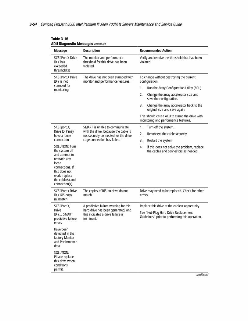
3-54 Compaq ProLiant 8000 Intel Pentium III Xeon 700MHz Servers Maintenance and Service Guide
Table 3-16ADU Diagnostic Messages continued
Message Description Recommended Action
SCSI Port X DriveID Y hasexceededthreshold(s)
The monitor and performancethreshold for this drive has beenviolated.
Verify and resolve the threshold that has beenviolated.
SCSI Port X DriveID Y is notstamped formonitoring
The drive has not been stamped withmonitor and performance features.
To change without destroying the currentconfiguration:
1. Run the Array Configuration Utility (ACU).
2. Change the array accelerator size andsave the configuration.
3. Change the array accelerator back to theoriginal size and save again.
This should cause ACU to stamp the drive withmonitoring and performance features.
SCSI port X,Drive ID Y mayhave a looseconnection
SOLUTION: Turnthe system offand attempt toreattach anylooseconnections. Ifthis does notwork, replacethe cable(s) andconnection(s).
SMART is unable to communicatewith the drive, because the cable isnot securely connected, or the drivecage connection has failed.
1. Turn off the system.
2. Reconnect the cable securely.
3. Restart the system.
4. If this does not solve the problem, replacethe cables and connectors as needed.
SCSI Port x DriveID Y RIS copymismatch
The copies of RIS on drive do notmatch.
Drive may need to be replaced. Check for othererrors.
SCSI Port X,DriveID Y…SMARTpredictive failureerrors
Have beendetected in thefactory Monitorand Performancedata.
SOLUTION:Please replacethis drive whenconditionspermit.
A predictive failure warning for thishard drive has been generated, andthis indicates a drive failure isimminent.
Replace this drive at the earliest opportunity.
See “Hot-Plug Hard Drive ReplacementGuidelines” prior to performing this operation.
continued
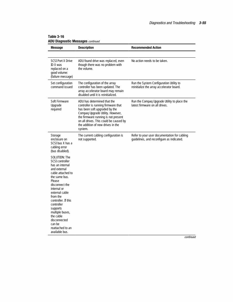
Diagnostics and Troubleshooting 3-55
Table 3-16ADU Diagnostic Messages continued
Message Description Recommended Action
SCSI Port X DriveID X wasreplaced on agood volume:(failure message)
ADU found drive was replaced, eventhough there was no problem withthe volume.
No action needs to be taken.
Set configurationcommand issued
The configuration of the arraycontroller has been updated. Thearray accelerator board may remaindisabled until it is reinitialized.
Run the System Configuration Utility toreinitialize the array accelerator board.
Soft FirmwareUpgraderequired
ADU has determined that thecontroller is running firmware thathas been soft upgraded by theCompaq Upgrade Utility. However,the firmware running is not presenton all drives. This could be caused bythe addition of new drives in thesystem.
Run the Compaq Upgrade Utility to place thelatest firmware on all drives.
Storageenclosure onSCSI bus X has acabling error(bus disabled).
SOLUTION: TheSCSI controllerhas an internaland externalcable attached tothe same bus.Pleasedisconnect theinternal orexternal cablefrom thecontroller. If thiscontrollersupportsmultiple buses,the cabledisconnectedcan bereattached to anavailable bus.
The current cabling configuration isnot supported.
Refer to your user documentation for cablingguidelines, and reconfigure as indicated.
continued
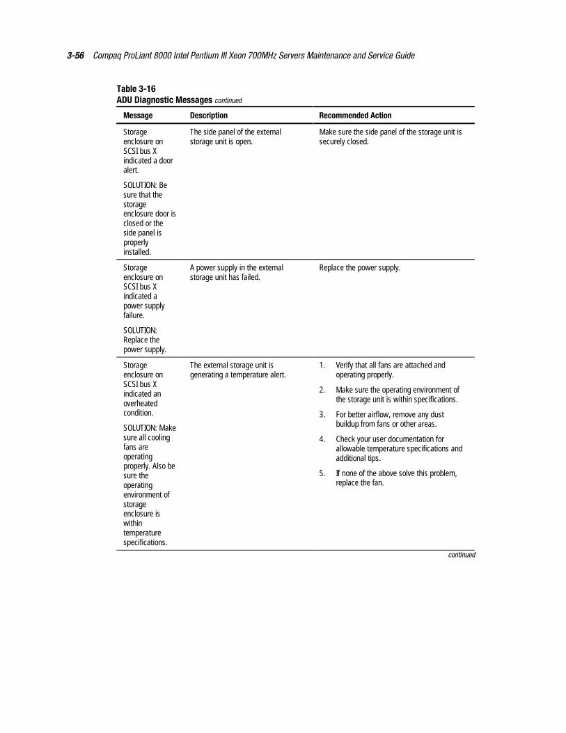
3-56 Compaq ProLiant 8000 Intel Pentium III Xeon 700MHz Servers Maintenance and Service Guide
Table 3-16ADU Diagnostic Messages continued
Message Description Recommended Action
Storageenclosure onSCSI bus Xindicated a dooralert.
SOLUTION: Besure that thestorageenclosure door isclosed or theside panel isproperlyinstalled.
The side panel of the externalstorage unit is open.
Make sure the side panel of the storage unit issecurely closed.
Storageenclosure onSCSI bus Xindicated apower supplyfailure.
SOLUTION:Replace thepower supply.
A power supply in the externalstorage unit has failed.
Replace the power supply.
Storageenclosure onSCSI bus Xindicated anoverheatedcondition.
SOLUTION: Makesure all coolingfans areoperatingproperly. Also besure theoperatingenvironment ofstorageenclosure iswithintemperaturespecifications.
The external storage unit isgenerating a temperature alert.
1. Verify that all fans are attached andoperating properly.
2. Make sure the operating environment ofthe storage unit is within specifications.
3. For better airflow, remove any dustbuildup from fans or other areas.
4. Check your user documentation forallowable temperature specifications andadditional tips.
5. If none of the above solve this problem,replace the fan.
continued
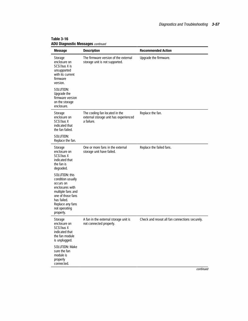
Diagnostics and Troubleshooting 3-57
Table 3-16ADU Diagnostic Messages continued
Message Description Recommended Action
Storageenclosure onSCSI bus X isunsupportedwith its currentfirmwareversion.
SOLUTION:Upgrade thefirmware versionon the storageenclosure.
The firmware version of the externalstorage unit is not supported.
Upgrade the firmware.
Storageenclosure onSCSI bus Xindicated thatthe fan failed.
SOLUTION:Replace the fan.
The cooling fan located in theexternal storage unit has experienceda failure.
Replace the fan.
Storageenclosure onSCSI bus Xindicated thatthe fan isdegraded.
SOLUTION: thiscondition usuallyoccurs onenclosures withmultiple fans andone of those fanshas failed.Replace any fansnot operatingproperly.
One or more fans in the externalstorage unit have failed.
Replace the failed fans.
Storageenclosure onSCSI bus Xindicated thatthe fan moduleis unplugged.
SOLUTION: Makesure the fanmodule isproperlyconnected.
A fan in the external storage unit isnot connected properly.
Check and reseat all fan connections securely.
continued
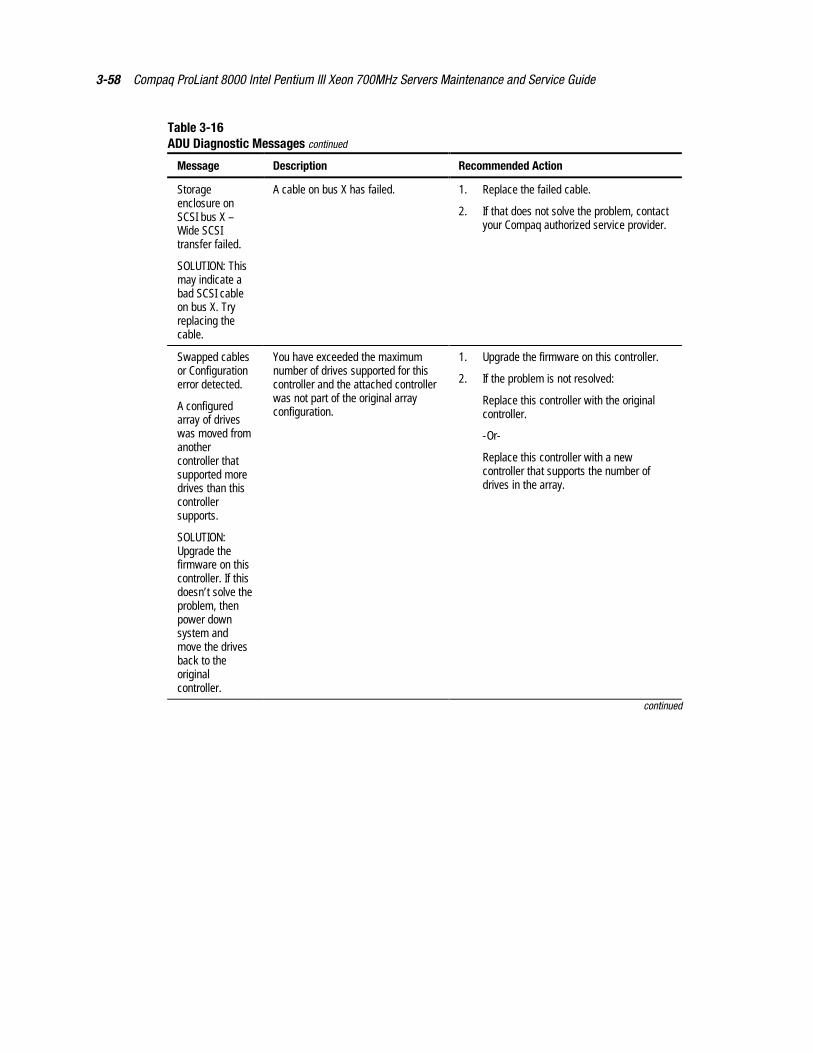
3-58 Compaq ProLiant 8000 Intel Pentium III Xeon 700MHz Servers Maintenance and Service Guide
Table 3-16ADU Diagnostic Messages continued
Message Description Recommended Action
Storageenclosure onSCSI bus X –Wide SCSItransfer failed.
SOLUTION: Thismay indicate abad SCSI cableon bus X. Tryreplacing thecable.
A cable on bus X has failed. 1. Replace the failed cable.
2. If that does not solve the problem, contactyour Compaq authorized service provider.
Swapped cablesor Configurationerror detected.
A configuredarray of driveswas moved fromanothercontroller thatsupported moredrives than thiscontrollersupports.
SOLUTION:Upgrade thefirmware on thiscontroller. If thisdoesn’t solve theproblem, thenpower downsystem andmove the drivesback to theoriginalcontroller.
You have exceeded the maximumnumber of drives supported for thiscontroller and the attached controllerwas not part of the original arrayconfiguration.
1. Upgrade the firmware on this controller.
2. If the problem is not resolved:
Replace this controller with the originalcontroller.
-Or-
Replace this controller with a newcontroller that supports the number ofdrives in the array.
continued
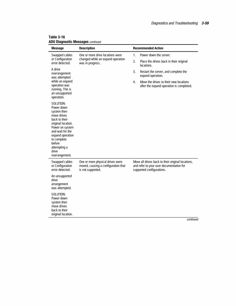
Diagnostics and Troubleshooting 3-59
Table 3-16ADU Diagnostic Messages continued
Message Description Recommended Action
Swapped cablesor Configurationerror detected.
A driverearrangementwas attemptedwhile an expandoperation wasrunning. This isan unsupportedoperation.
SOLUTION:Power downsystem thenmove drivesback to theiroriginal location.Power on systemand wait for theexpand operationto completebeforeattempting adriverearrangement.
One or more drive locations werechanged while an expand operationwas in progress.
1. Power down the server.
2. Place the drives back in their originallocations.
3. Restart the server, and complete theexpand operation.
4. Move the drives to their new locationsafter the expand operation is completed.
Swapped cablesor Configurationerror detected.
An unsupporteddrivearrangementwas attempted.
SOLUTION:Power downsystem thenmove drivesback to theiroriginal location.
One or more physical drives weremoved, causing a configuration thatis not supported.
Move all drives back to their original locations,and refer to your user documentation forsupported configurations.
continued
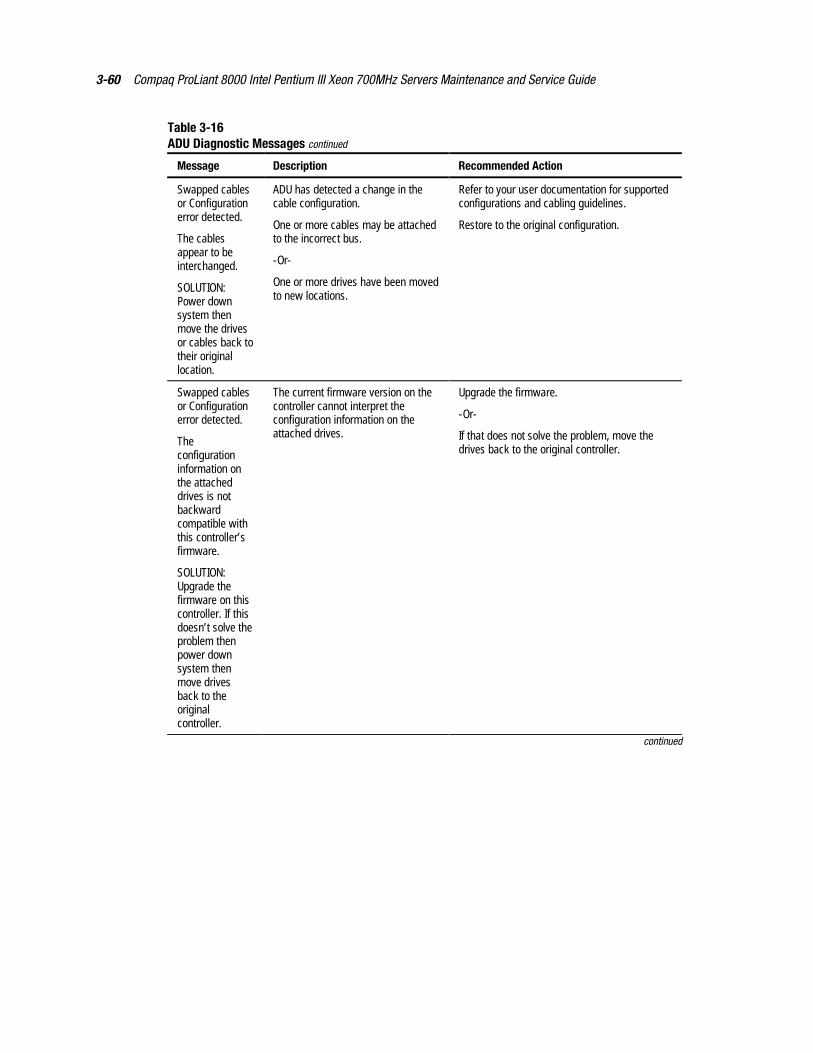
3-60 Compaq ProLiant 8000 Intel Pentium III Xeon 700MHz Servers Maintenance and Service Guide
Table 3-16ADU Diagnostic Messages continued
Message Description Recommended Action
Swapped cablesor Configurationerror detected.
The cablesappear to beinterchanged.
SOLUTION:Power downsystem thenmove the drivesor cables back totheir originallocation.
ADU has detected a change in thecable configuration.
One or more cables may be attachedto the incorrect bus.
-Or-
One or more drives have been movedto new locations.
Refer to your user documentation for supportedconfigurations and cabling guidelines.
Restore to the original configuration.
Swapped cablesor Configurationerror detected.
Theconfigurationinformation onthe attacheddrives is notbackwardcompatible withthis controller’sfirmware.
SOLUTION:Upgrade thefirmware on thiscontroller. If thisdoesn’t solve theproblem thenpower downsystem thenmove drivesback to theoriginalcontroller.
The current firmware version on thecontroller cannot interpret theconfiguration information on theattached drives.
Upgrade the firmware.
-Or-
If that does not solve the problem, move thedrives back to the original controller.
continued

Diagnostics and Troubleshooting 3-61
Table 3-16ADU Diagnostic Messages continued
Message Description Recommended Action
Swapped cablesor Configurationerror detected.
The maximumlogical volumecount X wasexceeded duringlogical volumeaddition. Alllogical volumesbeyond X havebeen lost andcannot berecovered.
SOLUTION:Identify thedrives thatcontain the lostlogical volumes.Move thosedrives to anothercontroller wherethe logicalvolumes can berecreated.NOTE! If a drivecontains a validlogical volumeand a lost logicalvolume, then donot move thatdrive to anothercontroller.
More logical drives were createdthan are supported on this controller,causing lost logical drive volumes.
Identify the drives containing lost volumes, andmove them to another controller so the lostvolumes can be recreated.
WARNING: Do not move a drive if it alsocontains valid volume data. This process willcause all valid data to be destroyed!
continued
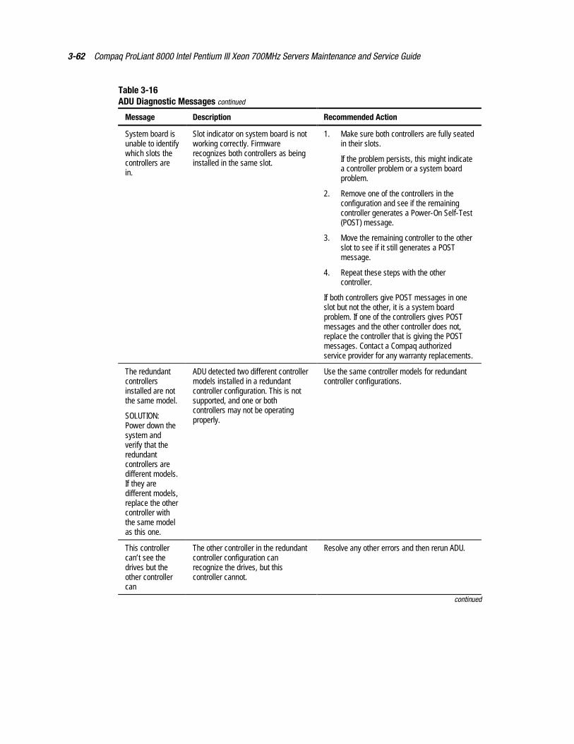
3-62 Compaq ProLiant 8000 Intel Pentium III Xeon 700MHz Servers Maintenance and Service Guide
Table 3-16ADU Diagnostic Messages continued
Message Description Recommended Action
System board isunable to identifywhich slots thecontrollers arein.
Slot indicator on system board is notworking correctly. Firmwarerecognizes both controllers as beinginstalled in the same slot.
1. Make sure both controllers are fully seatedin their slots.
If the problem persists, this might indicatea controller problem or a system boardproblem.
2. Remove one of the controllers in theconfiguration and see if the remainingcontroller generates a Power-On Self-Test(POST) message.
3. Move the remaining controller to the otherslot to see if it still generates a POSTmessage.
4. Repeat these steps with the othercontroller.
If both controllers give POST messages in oneslot but not the other, it is a system boardproblem. If one of the controllers gives POSTmessages and the other controller does not,replace the controller that is giving the POSTmessages. Contact a Compaq authorizedservice provider for any warranty replacements.
The redundantcontrollersinstalled are notthe same model.
SOLUTION:Power down thesystem andverify that theredundantcontrollers aredifferent models.If they aredifferent models,replace the othercontroller withthe same modelas this one.
ADU detected two different controllermodels installed in a redundantcontroller configuration. This is notsupported, and one or bothcontrollers may not be operatingproperly.
Use the same controller models for redundantcontroller configurations.
This controllercan’t see thedrives but theother controllercan
The other controller in the redundantcontroller configuration canrecognize the drives, but thiscontroller cannot.
Resolve any other errors and then rerun ADU.
continued
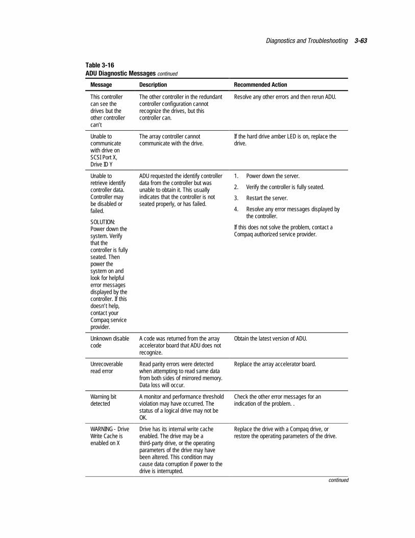
Diagnostics and Troubleshooting 3-63
Table 3-16ADU Diagnostic Messages continued
Message Description Recommended Action
This controllercan see thedrives but theother controllercan’t
The other controller in the redundantcontroller configuration cannotrecognize the drives, but thiscontroller can.
Resolve any other errors and then rerun ADU.
Unable tocommunicatewith drive onSCSI Port X,Drive ID Y
The array controller cannotcommunicate with the drive.
If the hard drive amber LED is on, replace thedrive.
Unable toretrieve identifycontroller data.Controller maybe disabled orfailed.
SOLUTION:Power down thesystem. Verifythat thecontroller is fullyseated. Thenpower thesystem on andlook for helpfulerror messagesdisplayed by thecontroller. If thisdoesn’t help,contact yourCompaq serviceprovider.
ADU requested the identify controllerdata from the controller but wasunable to obtain it. This usuallyindicates that the controller is notseated properly, or has failed.
1. Power down the server.
2. Verify the controller is fully seated.
3. Restart the server.
4. Resolve any error messages displayed bythe controller.
If this does not solve the problem, contact aCompaq authorized service provider.
Unknown disablecode
A code was returned from the arrayaccelerator board that ADU does notrecognize.
Obtain the latest version of ADU.
Unrecoverableread error
Read parity errors were detectedwhen attempting to read same datafrom both sides of mirrored memory.Data loss will occur.
Replace the array accelerator board.
Warning bitdetected
A monitor and performance thresholdviolation may have occurred. Thestatus of a logical drive may not beOK.
Check the other error messages for anindication of the problem. .
WARNING - DriveWrite Cache isenabled on X
Drive has its internal write cacheenabled. The drive may be athird-party drive, or the operatingparameters of the drive may havebeen altered. This condition maycause data corruption if power to thedrive is interrupted.
Replace the drive with a Compaq drive, orrestore the operating parameters of the drive.
continued
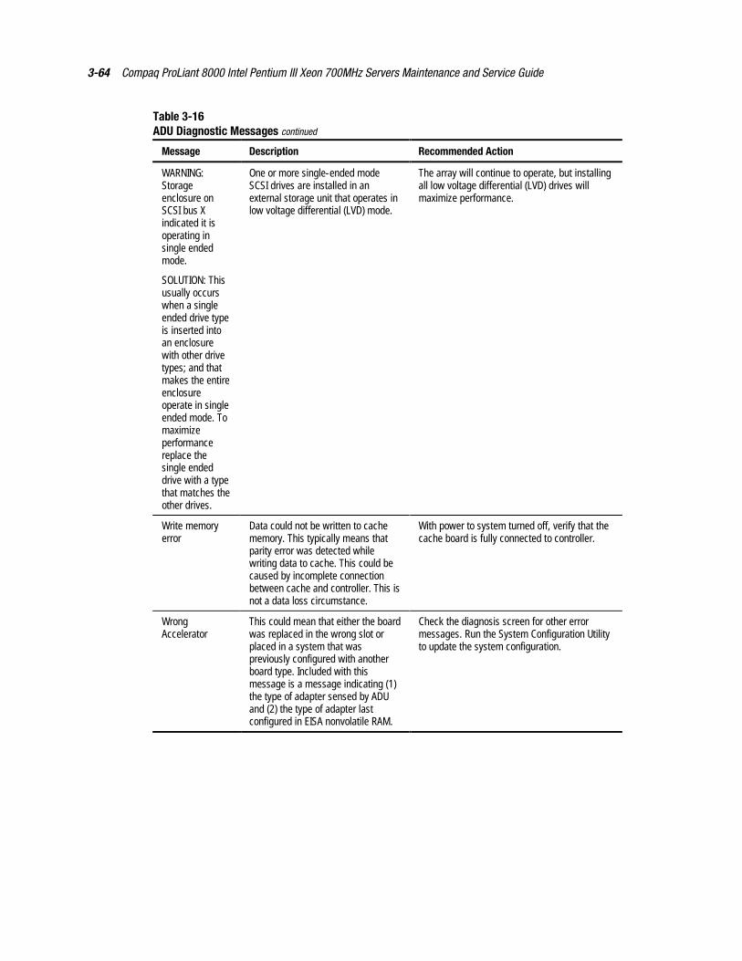
3-64 Compaq ProLiant 8000 Intel Pentium III Xeon 700MHz Servers Maintenance and Service Guide
Table 3-16ADU Diagnostic Messages continued
Message Description Recommended Action
WARNING:Storageenclosure onSCSI bus Xindicated it isoperating insingle endedmode.
SOLUTION: Thisusually occurswhen a singleended drive typeis inserted intoan enclosurewith other drivetypes; and thatmakes the entireenclosureoperate in singleended mode. Tomaximizeperformancereplace thesingle endeddrive with a typethat matches theother drives.
One or more single-ended modeSCSI drives are installed in anexternal storage unit that operates inlow voltage differential (LVD) mode.
The array will continue to operate, but installingall low voltage differential (LVD) drives willmaximize performance.
Write memoryerror
Data could not be written to cachememory. This typically means thatparity error was detected whilewriting data to cache. This could becaused by incomplete connectionbetween cache and controller. This isnot a data loss circumstance.
With power to system turned off, verify that thecache board is fully connected to controller.
WrongAccelerator
This could mean that either the boardwas replaced in the wrong slot orplaced in a system that waspreviously configured with anotherboard type. Included with thismessage is a message indicating (1)the type of adapter sensed by ADUand (2) the type of adapter lastconfigured in EISA nonvolatile RAM.
Check the diagnosis screen for other errormessages. Run the System Configuration Utilityto update the system configuration.
Diagnostics and Troubleshooting 3-65
Integrated Management LogOn servers supporting the Integrated Management Display, the Compaq Integrated ManagementLog (IML) replaces the Critical Error Log and Correctable Memory Logs. IML records systemevents and stores them in an easily viewable form. Each event is marked with a time-stamp withone-minute granularity.
Events listed in the Integrated Management Log are categorized as one of four event severitylevels:
� Status—indicates that the message is informational only.
� Repaired—indicates that corrective action has been taken.
� Caution—indicates a nonfatal error condition.
� Critical—indicates a component failure.
The Integrated Management Log requires Compaq operating system-dependent drivers. Refer tothe Compaq Support Software CD for instructions on installing the appropriate drivers.
Refer to the setup and installation guide that came with the server or to the IntegratedManagement Display User Guide provided with the Integrated Management Display option kit.
Multiple Ways of Viewing the Log
You can view an event in the IML in several ways:
� On the Integrated Management Display
� From within Compaq Insight Manager
� From within the Compaq Survey Utility
� From within the IML Management Utility
Integrated Management Display
The Integrated Management Display is an LCD panel that presents information directly at theserver, assisting in diagnosing and servicing the server without a keyboard and monitor.
Compaq Insight Manager
Compaq Insight Manager is a comprehensive management tool used to monitor and control theoperation of Compaq servers and clients. Compaq Insight Manager consists of two components:a Windows-based console application, and server- or client-based management data collectionagents. Starting with Compaq Insight Manager 4.0, the agents for Windows NT and NetWareare also Web-enhanced; that is, these agents enable Web browser access and monitoring ofmanagement information.
The management agents monitor over 1,000 management parameters. Key subsystems areinstrumented to make health, configuration, and performance data available to agent software.Agents act upon data by initiating information, such as statistics on network interface or storagesubsystem performance.

3-66 Compaq ProLiant 8000 Intel Pentium III Xeon 700MHz Servers Maintenance and Service Guide
Viewing the Event List
1. From Compaq Insight Manager, select the appropriate server, then select View DeviceData. The selected server displays, with buttons around its perimeter.
2. Select the Recovery button, then Integrated Management Log.
3. If a failed component has been replaced, select the event from the list. Then selectMark Repaired.
Printing the Event List
NOTE: You can only view the event list from the Recovery/Integrated Management Log screen asdescribed above.
1. From the Compaq Insight Manager screen, select the appropriate server.
2. Select the Configuration button, Recovery button, then Print.
Compaq Survey Utility
The Compaq Survey Utility is a serviceability tool available for Windows NT and NovellNetWare. It delivers online-configuration capture and comparison to maximize serveravailability. It is delivered on the Compaq Management CD in the SmartStart package or isavailable on the Compaq website. Refer to the Compaq Management CD for information oninstalling and running the Compaq Survey Utility.
After running the Compaq Survey Utility, view the IML by loading the output of the utility(typically called “survey.txt”) into a text viewer such as Microsoft Notepad. The event listfollows the system slot information. After opening the text file, print it using the print feature ofthe viewer.
Compaq IML Management Utility
The Compaq IML Management Utility is a DOS-based tool that gives you the offline ability toreview, mark corrected, and print events from the IML. It is located on the Compaq SmartStartand Support Software CD. Refer to the SmartStart Installation for Servers poster, which shipswith the server, for information on how to install and use the IML Management Utility.
Diagnostics and Troubleshooting 3-67
Event List
The Event List displays the affected components and the associated error messages. Althoughthe same basic information displays, the format of the list may differ, depending on how youview it: on the Integrated Management Display, from within Compaq Insight Manager, orthrough the Compaq Survey Utility. An example of the format of an event displayed on theIntegrated Management Display is as follows:
**001 of 010**---caution---03/19/199912:54 PMFAN INSERTEDMain SystemLocation: System BoardFan ID: 03**END OF EVENT**
Event Messages
Table 3-17Event Messages
Event Type Event Message Action
Machine Environment
Fan Failure System Fan Failure (Fan X, Location). Replace fan.
Fan Inserted System Fan Inserted (Fan X, Location). None
Fan Removed System Fan Removed (Fan X, Location). None
Fans Not Redundant System Fans Not Redundant. Add fan.
Overheat Condition System Overheating (Zone X, Location). Check fans.
Main Memory
Correctable Errorthreshold exceeded
Corrected Memory Error threshold passed(Slot X, Memory Module X).
Replace the defective memorymodule.
Corrected Memory Error threshold passed(System Memory).
Replace the memory modules oneat a time (if more than one) andretest the system after eachreplacement.
Corrected Memory Error threshold passed(Memory Module unknown).
Replace the memory modules oneat a time (if more than one).
Uncorrectable Error Uncorrectable Memory Error (Slot X,Memory Module X).
Replace the defective memorymodule.
Uncorrectable Memory Error (SystemMemory).
Replace the defective memorymodule.
continued
3-68 Compaq ProLiant 8000 Intel Pentium III Xeon 700MHz Servers Maintenance and Service Guide
Table 3-17Event Messages continued
Event Type Event Message Action
Uncorrectable Memory Error (MemoryModule unknown).
Replace the memory modules oneat a time (if more than one) andretest the system after eachreplacement.
Processor
Correctable ErrorThreshold exceeded
Processor Correctable error Thresholdpassed (Slot X, Socket X).
Replace the processor.
Uncorrectable Error Unrecoverable Host Bus Data Parity Error. Replace the processor.
Host Bus Error Unrecoverable Host Bus Address ParityError.
Call the service provider or Compaqfor diagnosis.
EISA Bus EISA Expansion Bus Master Timeout(Slot X).
EISA Expansion Bus Slave Timeout.
EISA Expansion Board Error (Slot X).
EISA Expansion Bus Arbitration Error.
Turn off server and replace EISAboard.
PCI Bus Error PCI Bus Error (Slot X, Bus X, Device X,Function X).
Power down PCI slot and replaceboard.
Power Subsystem
Power Supply Failure System Power Supply Failure (PowerSupply X).
Replace power supply.
Power Supply Inserted System Power Supply Inserted (PowerSupply X).
None
Power Supply Removed System Power Supply Removed (PowerSupply X).
None
Power SupplyNot Redundant
System Power Supplies Not Redundant. Add power supply.
System ConfigurationBattery Low
Real-Time Clock Battery Failing. Replace battery.
Power Module Failure A CPU Power Module (System Board,Socket X).
Replace power module.
Power Module Failure A CPU Power Module (Slot X, Socket X). Replace power module.
Power Modules NotRedundant
System Power Modules Not Redundant. Add power module.
AC Voltage Problem System AC Power Problem (PowerSupply X).
Check the input power voltage.
Power AC Overload System AC Power Overload (PowerSupply X).
� Change the input power to220V.
� Add an additional powersupply, or replace with oneable to supply present load.
� Reduce the load.continued
Diagnostics and Troubleshooting 3-69
Table 3-17Event Messages continued
Event Type Event Message Action
Automatic Server Recovery –2
System Lockup ASR Lockup Detected: Cause Call the service provider or Compaqfor diagnosis.
Operating System
Blue Screen Trap: Cause [NT]
Kernel Panic: Cause [UNIX]
System Crash
Abnormal Program Termination: Cause[NetWare]
Refer to the documentation for theoperating system.
Automatic Operating System ShutdownInitiated Due to Fan Failure
Automatic Operating System ShutdownInitiated Due to Overheat Condition
Automatic OSShutdown
Fatal Exception (Number X, Cause)
Refer to the documentation for theoperating system.
3-70 Compaq ProLiant 8000 Intel Pentium III Xeon 700MHz Servers Maintenance and Service Guide
Rapid Error RecoveryCompaq servers provide rapid recovery services for diagnosing and recovering from errors.These tools are available for local and remote diagnosis and recovery.
Rapid recovery means fast identification and resolution of complex faults. The Rapid RecoveryEngine and Insight Management Agents notify the system administrator when a failure occurs,ensuring that the server experiences minimal downtime. These features are enabled through theSystem Configuration Utility. These integrated server management features are:
� Automatic Server Recovery-2 (ASR-2)
� Integrated Management Logs
� Server Health Logs (on servers not supporting Integrated Management Logs)
� Storage Fault Recovery Tracking
� Storage Automatic Reconstruction
� Network Interface Fault Recovery Tracking
� Memory Fault Recovery Tracking (with option upgrade kit)
� Remote-Flash Redundant ROM
These features are discussed in more detail on the server documentation CD.
Automatic Server Recovery-2
Automatic Server Recovery-2 (ASR-2) lets the server restart automatically from the operatingsystem or the Compaq Utilities. To use this feature, you must use the System ConfigurationUtility to install Compaq Utilities in the system partition.
You can enable the ASR-2 feature to restart a server after a critical hardware or software erroroccurs. If a critical error occurs, the server records the error information in the IntegratedManagement Log (IML), restarts the system, and pages you. Using the Compaq SystemConfiguration Utility, configure the system for automatic recovery or for attended local orremote access to diagnostic and configuration tools.
NOTE: ASR-2 is available only on operating systems using the ASR-2 drivers provided by Compaq.
You can also configure ASR-2 to page an administrator when the system restarts. ASR-2depends on the application and driver that routinely notify the ASR-2 hardware of propersystem operations. If the time between ASR-2 notifications exceeds the specified period, ASR-2assumes a fault has occurred and initiates the recovery process.
To configure ASR-2:
1. Run the System Configuration Utility.
2. Select View and Edit Details.
3. Set the software error recovery status to Enabled.
4. Set the software error recovery timeout.
Diagnostics and Troubleshooting 3-71
The available recovery features are:
� Software Error Recovery—automatically restarts the server after a software-inducedserver failure
� Environmental Recovery—allows the server to restart when temperature, fan, orAC power conditions return to normal
Unattended Recovery
For unattended recovery, ASR-2 performs the following actions:
� Logs the error information to the IML
� Resets the server
� Pages you (if a modem is present and you selected Paging)
� Tries to restart the operating system
Often the server restarts successfully, making unattended recovery the ideal choice for remotelocations where trained service personnel are not immediately available.
If ASR-2 cannot restart the server within 10 attempts, it places a critical error in the IntegratedManagement Log, starts the server into Compaq Utilities, and enables remote access (if youconfigured remote access).
To use this level of ASR-2, you must configure ASR-2 to load the operating system after restart.
Attended Recovery
For attended recovery, ASR-2 performs the following actions:
� Logs the error information to the IML
� Resets the server
� Pages you (if a modem is present and you selected Paging)
� Starts Compaq Utilities from the hard drive
� Enables remote access
During system configuration, these utilities are placed on the system utilities partition of thehard drive.
If you have configured for dial-in access and have a modem with an auto-answer featureinstalled, you can dial in and remotely diagnose or reconfigure the server.
If you have configured the Compaq Utilities for network access, you can access the utilities overthe network. You can use Compaq Insight Manager for dial-in or network access.

3-72 Compaq ProLiant 8000 Intel Pentium III Xeon 700MHz Servers Maintenance and Service Guide
Hardware Requirements
To use this level of ASR-2 over a modem, you need the following:
� An external Hayes-compatible modem
NOTE: ASR does not work with PCI modems.
� System Configuration Utility and Diagnostics Utility installed on the system partition ofthe hard drive
� ASR-2 configured to load Compaq Utilities after restart
You can also run Compaq Utilities remotely over an IPX or IP network using the Networkfeature:
� To use Compaq Utilities on an IPX network, you must have Compaq Insight Manager 2.0or later or a Novell Virtual Terminal (NVT) Terminal Emulator with VT100 or ANSIterminal capabilities.
� To use Compaq Utilities on an IP network, you must have Compaq Insight Manager 2.10or later, or a Telnet Terminal Emulator with VT100 or ANSI capabilities.
If you are notified that ASR-2 restarted the server and you have restarted to Compaq Utilities,use the Inspect Utility or Compaq Insight Manager to view the critical error in the Critical ErrorLog. Run Diagnostics to diagnose and resolve the problem.
You can configure ASR-2 to restart the server into Compaq Utilities to diagnose the criticalerror or to start the operating system to return the server to operational status as rapidly aspossible.
When you enable ASR-2 to start the operating system, the server tries to start from the primarypartition. In this mode, ASR-2 can page you if a critical error occurs, but you cannot accessCompaq Utilities.
When you enable ASR-2 to start Compaq Utilities, the server restarts after a critical error andloads Compaq Utilities from the system partition on the hard drive.
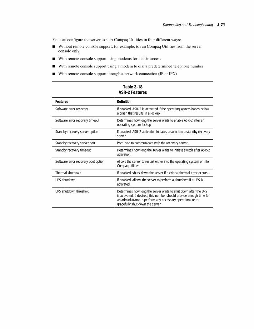
Diagnostics and Troubleshooting 3-73
You can configure the server to start Compaq Utilities in four different ways:
� Without remote console support; for example, to run Compaq Utilities from the serverconsole only
� With remote console support using modems for dial-in access
� With remote console support using a modem to dial a predetermined telephone number
� With remote console support through a network connection (IP or IPX)
Table 3-18ASR-2 Features
Features Definition
Software error recovery If enabled, ASR-2 is activated if the operating system hangs or hasa crash that results in a lockup.
Software error recovery timeout Determines how long the server waits to enable ASR-2 after anoperating system lockup
Standby recovery server option If enabled, ASR-2 activation initiates a switch to a standby recoveryserver.
Standby recovery server port Port used to communicate with the recovery server.
Standby recovery timeout Determines how long the server waits to initiate switch after ASR-2activation.
Software error recovery boot option Allows the server to restart either into the operating system or intoCompaq Utilities.
Thermal shutdown If enabled, shuts down the server if a critical thermal error occurs.
UPS shutdown If enabled, allows the server to perform a shutdown if a UPS isactivated.
UPS shutdown threshold Determines how long the server waits to shut down after the UPSis activated. If desired, this number should provide enough time foran administrator to perform any necessary operations or togracefully shut down the server.
3-74 Compaq ProLiant 8000 Intel Pentium III Xeon 700MHz Servers Maintenance and Service Guide
Compaq Integrated Remote Console
The standard Compaq Integrated Remote Console performs a wide range of configurationactivities. Console features include:
� Is accessible using ANSI terminal
� Operates independently of the operating system
� Provides for remote server reboot
� Provides access to system configuration
� Uses out-of-band communication with dedicated management modem installed in theserver
For more information, see the Integrated Remote Console User Guide that shipped with theserver.
IMPORTANT: Before configuring ASR-2, verify that the System Configuration Utility and Diagnosticssoftware are installed on the system partition. ASR-2 must have this to start Compaq Utilities after asystem restart. Compaq recommends this even if you configure ASR-2 to start the operating system.
Compaq Health Driver
The Compaq Health Driver continually resets the ASR-2 timer according to the frequency youspecified in the System Configuration Utility (for example, 10 minutes). If the ASR-2 timercounts down to zero before being reset, due to an operating system crash or a server lockup,ASR-2 restarts the server into either Compaq Utilities or the operating system (as indicated bythe System Configuration parameters). The default value is 10 minutes. The allowable settingsare 5, 10, 20, and 30 minutes.
For remote and off-site (unattended) servers, setting the software error recovery timeout for5 minutes reduces server downtime and allows the server to recover quickly. For local(attended) servers located on site, you can set the software error recovery timeout for20 or 30 minutes, giving you time to arrive at the server to manually diagnose the problem.
The Compaq Health Driver is independent of the ASR-2 timer. You must load the Health Driverand enable the ASR-2 timer. This allows the driver to detect and log information in the IMLregarding numerous hardware and software errors. However, you cannot enable the ASR-2timer without loading the Compaq Health Driver.
Before ASR-2 restarts the server, it records any information available about the condition of theoperating system in the Critical Error Log or the IML depending on the server support. Thisinformation can be used to diagnose an operating system crash or server lock-up, while stillallowing the server to be restarted.
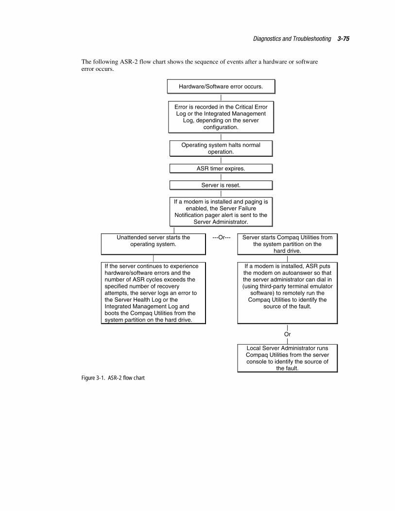
Diagnostics and Troubleshooting 3-75
The following ASR-2 flow chart shows the sequence of events after a hardware or softwareerror occurs.
Hardware/Software error occurs.
|
Error is recorded in the Critical ErrorLog or the Integrated Management
Log, depending on the serverconfiguration.
|Operating system halts normal
operation.|
ASR timer expires.|
Server is reset.|
If a modem is installed and paging isenabled, the Server Failure
Notification pager alert is sent to theServer Administrator.
|Unattended server starts the
operating system.---Or--- Server starts Compaq Utilities from
the system partition on thehard drive.
|If the server continues to experiencehardware/software errors and thenumber of ASR cycles exceeds thespecified number of recoveryattempts, the server logs an error tothe Server Health Log or theIntegrated Management Log andboots the Compaq Utilities from thesystem partition on the hard drive.
If a modem is installed, ASR putsthe modem on autoanswer so thatthe server administrator can dial in(using third-party terminal emulator
software) to remotely run theCompaq Utilities to identify the
source of the fault.
|Or|
Local Server Administrator runsCompaq Utilities from the serverconsole to identify the source of
the fault.
Figure 3-1. ASR-2 flow chart
3-76 Compaq ProLiant 8000 Intel Pentium III Xeon 700MHz Servers Maintenance and Service Guide
Booting into Compaq Utilities
When you enable ASR-2 to start into Compaq Utilities and a critical error occurs, the operatingsystem-specific Health Driver logs the error information in the Critical Error Log or the IMLand the ASR-2 feature restarts the server. When the system reinitializes, the system pages thedesignated administrator (if enabled) and starts Compaq Utilities from the hard drive.
If Dial-In status is enabled, the modem is placed in auto-answer mode. If you enable Dial-Outstatus, you are automatically enabled for Dial-In.
If Network Status is enabled, the appropriate network support software is loaded, depending onthe network protocol, IP or IPX. This allows remote access by means of the network.
IMPORTANT: Compaq Utilities are loaded from a specially created system partition on the hard drive.This partition was configured during server configuration.
You can access the server and view the Server Health Logs (in servers not supporting the IML)remotely by modem, in-band over the network, or directly from the server. For modem access,you must have either Compaq Insight Manager 2.0 or later or have a VT100 or ANSI terminaltype device. You can use a standard CRT with VT100 or ANSI emulation capability, or you canuse a PC with a VT100 or ANSI terminal emulation package. The communication parametersmust be set for 8 data bits, no parity, and 1 stop bit.
You can also enable ASR-2 to allow network access using the Network Status feature in theSystem Configuration Utility. You must have either Compaq Insight Manager 2.0 or later or aNovell Virtual Terminal (NVT) emulator on an IPX network to use this feature. You must alsohave version 2.24 or later of the Compaq System Configuration Utility. For IP access, you musthave Compaq Insight Manager 2.10 or later, or a Telnet Terminal emulator to use this feature.You also must have version 2.24 or later of the Compaq System Configuration Utility.
The System Configuration Utility settings should resemble the settings in Table 3-19 when youenable ASR-2 to start into Compaq Utilities.
Table 3-19Compaq System Configuration Utility Pager Settings for Booting into Compaq Utilities
Pager Data Setting Description
Pager status Enabled Indicates whether the pager feature is enabled or disabled
Pager dialstring
ATDT555-5555
Indicates the pager dial string and delay before the pager message;pagers typically use one of the following formats:
Local pagers: ATDT 555-5555
Wide area pagers: ATDT 1-800-555-5555,1234567#
Pager message 1234567# Represents a unique number (maximum seven digits, numeric only) thatyou must designate to identify the server on the pager display. The ROMadds a three-digit code to the front of this number. The first two indicatethe subsystem and the third indicates the severity of the error thatcaused the alert. The # symbol usually terminates the message. If nomessage is required, delete the # symbol.
continued
Diagnostics and Troubleshooting 3-77
Table 3-19Compaq System Configuration Utility Pager Settings for Booting into Compaq Utilities continued
Pager Data Setting Description
Pager test Select to testpager setup
Use this to test the current pager settings. Press Enter to dial the pagernumber, and the pager message (if present) displays. You mustconfigure the computer before testing the pager, and the Pager Statusmust be set to Enabled. Do not test the pager if you are runningremotely and are using only one modem.
Serial interface COM1 Select the communications port for the modem used by the pager andthe remote ASR-2 functions. The options are COM1 and COM2.
Dial-in status Enabled Set Dial-In Status to Enabled. Be sure the Reset Boot option is set toBoot Compaq Utilities. When the system starts because of an ASR reset,it starts to the Compaq Utilities, sets the Management Modem to auto-answer, and waits for the administrator to dial in and run the CompaqUtilities.
You automatically disable this option when you configure the softwareerror recovery start option to Boot Operating System. When ASR pagesyou, you cannot dial in unless ASR-2 exceeds 10, the threshold numberof server restart retries. When this happens, ASR-2 restarts the serverinto the Compaq Utilities and places the modem in auto-answer mode.
Dial-out status Enabled Allows ASR-2 to dial out to a remote workstation. If you selected thisoption, Dial-In Status is automatically selected.
To use the dial-out feature, set Dial-Out Status to Enabled and set theDial-Out String to the correct phone number. You must also set theReset Boot option to Boot Compaq Utilities. When the system restartsbecause of an ASR reset, the administrator is paged via Pager Statusand Pager Dial String, the system restarts to the Compaq Utilities, anddials out to the phone number provided in the Dial-Out string. Thedial-out number will be tried five times. If it fails to connect after fiveattempts, the modem is put in autoanswer mode.
Dial-out string 555-1234 Enter the dial string followed by the remote computer telephone number.
Network status Enabled To allow network access to Compaq Utilities, set Network Status toEnabled and ensure that the Reset Boot option is set to Boot CompaqUtilities.
Networkprotocol
To use IPX network access, set Network Protocol to IPX. When thesystem restarts to the Compaq Utilities because of an ASR reset, it loadsIPX network support. This enables remote access using NVT.
To use IP network access, set Network protocol to IP. Also make sure toset Network IP address, Network IP net mask, and Network IP routeraddress. When the system restarts to the Compaq Utilities because of anASR reset, it loads IP network support. This enables remote accessusing Telnet.
Note: The Network Status must be set to Enabled for network access.
Networkcontroller
Compaq For all Compaq standard network controllers.
continued
3-78 Compaq ProLiant 8000 Intel Pentium III Xeon 700MHz Servers Maintenance and Service Guide
Table 3-19Compaq System Configuration Utility Pager Settings for Booting into Compaq Utilities continued
Pager Data Setting Description
Network hostname
CPQHOU Enter the network name of the server. Use underscores instead ofspaces within the name, for example, Compaq_Server. If you are usingIPX network access to the Compaq Utilities, this server name is used toadvertise NVT host services. This server name displays in the CompaqInsight Manager server list when the program determines it cancommunicate using NVT. Set this name to be the same as the servername you assign when the host operating system is running.
Network cardslot
Slot # Select the slot number of the network interface card to be used fornetwork access to Compaq Utilities.
Network frametype
ETHERNET_I I Select the frame type for the network. Selections include both Ethernetand Token Ring topologies.
Network IPaddress
Enter the IP address for this server in standard dot notation.
Note: This is not used if you select Custom for Network controller. Youmust enter the IP address in the NET.CFG file that you load into thesystem partition.
Network IP netmask
Enter the net mask for this server in standard dot notation.
Note: This is not used if you select Custom for network controller. Youmust enter the IP address in the NET.CFG file that you load into thesystem partition.
Network IProuter address
Enter the router to be used for this server in standard dot notation.
Note: This is not used if you select Custom for network controller. Youmust enter the IP address in the NET.CFG file that you load into thesystem partition.
If you configure the server to boot into Compaq Utilities, it prepares for remotecommunications. You can remotely run Diagnostics software, the Inspect Utility, or the SystemConfiguration Utility using a workstation running terminal emulation software, such as CompaqInsight Manager or PC Anywhere.
Booting into the Operating System
When you enable ASR-2 to restart into the operating system and a critical error occurs, ASR-2logs the error in the Critical Error Log or IML and restarts the server. The system ROM pagesthe designated administrator, then executes the normal restart process.
IMPORTANT: When you enable ASR-2 to restart into the operating system, Modem Dial-In Status,Network Status, and Modem Dial-Out Status are automatically disabled. In this mode, ASR-2 can pageyou if a critical error occurs, but you cannot access the server, and the server cannot dial out to a remoteworkstation.
If the ASR-2 feature cannot restart the server within 10 attempts, it logs a critical error in theCritical Error Log or IML, restarts the server into the Compaq Utilities, and puts the modeminto auto-answer mode.
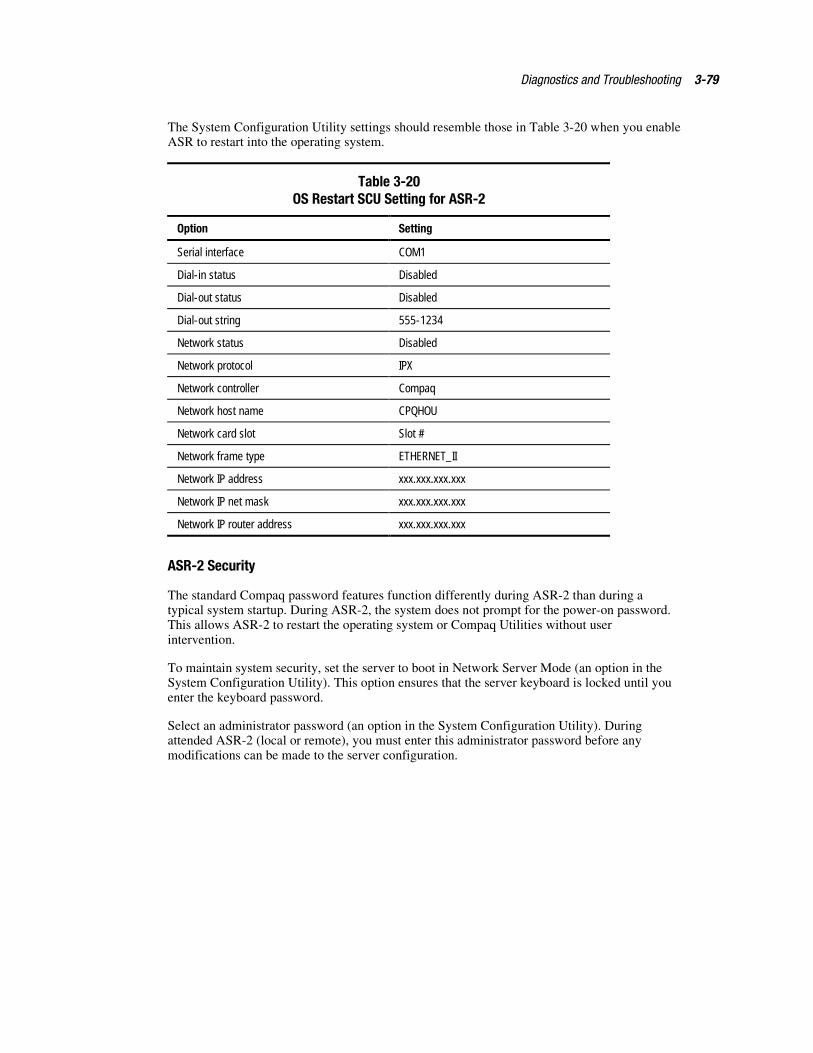
Diagnostics and Troubleshooting 3-79
The System Configuration Utility settings should resemble those in Table 3-20 when you enableASR to restart into the operating system.
Table 3-20OS Restart SCU Setting for ASR-2
Option Setting
Serial interface COM1
Dial-in status Disabled
Dial-out status Disabled
Dial-out string 555-1234
Network status Disabled
Network protocol IPX
Network controller Compaq
Network host name CPQHOU
Network card slot Slot #
Network frame type ETHERNET_II
Network IP address xxx.xxx.xxx.xxx
Network IP net mask xxx.xxx.xxx.xxx
Network IP router address xxx.xxx.xxx.xxx
ASR-2 Security
The standard Compaq password features function differently during ASR-2 than during atypical system startup. During ASR-2, the system does not prompt for the power-on password.This allows ASR-2 to restart the operating system or Compaq Utilities without userintervention.
To maintain system security, set the server to boot in Network Server Mode (an option in theSystem Configuration Utility). This option ensures that the server keyboard is locked until youenter the keyboard password.
Select an administrator password (an option in the System Configuration Utility). Duringattended ASR-2 (local or remote), you must enter this administrator password before anymodifications can be made to the server configuration.
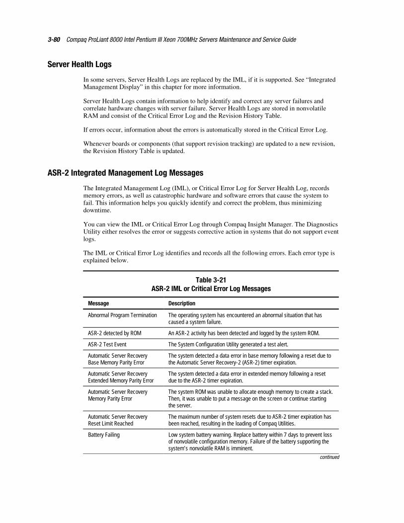
3-80 Compaq ProLiant 8000 Intel Pentium III Xeon 700MHz Servers Maintenance and Service Guide
Server Health Logs
In some servers, Server Health Logs are replaced by the IML, if it is supported. See “IntegratedManagement Display” in this chapter for more information.
Server Health Logs contain information to help identify and correct any server failures andcorrelate hardware changes with server failure. Server Health Logs are stored in nonvolatileRAM and consist of the Critical Error Log and the Revision History Table.
If errors occur, information about the errors is automatically stored in the Critical Error Log.
Whenever boards or components (that support revision tracking) are updated to a new revision,the Revision History Table is updated.
ASR-2 Integrated Management Log Messages
The Integrated Management Log (IML), or Critical Error Log for Server Health Log, recordsmemory errors, as well as catastrophic hardware and software errors that cause the system tofail. This information helps you quickly identify and correct the problem, thus minimizingdowntime.
You can view the IML or Critical Error Log through Compaq Insight Manager. The DiagnosticsUtility either resolves the error or suggests corrective action in systems that do not support eventlogs.
The IML or Critical Error Log identifies and records all the following errors. Each error type isexplained below.
Table 3-21ASR-2 IML or Critical Error Log Messages
Message Description
Abnormal Program Termination The operating system has encountered an abnormal situation that hascaused a system failure.
ASR-2 detected by ROM An ASR-2 activity has been detected and logged by the system ROM.
ASR-2 Test Event The System Configuration Utility generated a test alert.
Automatic Server RecoveryBase Memory Parity Error
The system detected a data error in base memory following a reset due tothe Automatic Server Recovery-2 (ASR-2) timer expiration.
Automatic Server RecoveryExtended Memory Parity Error
The system detected a data error in extended memory following a resetdue to the ASR-2 timer expiration.
Automatic Server RecoveryMemory Parity Error
The system ROM was unable to allocate enough memory to create a stack.Then, it was unable to put a message on the screen or continue startingthe server.
Automatic Server RecoveryReset Limit Reached
The maximum number of system resets due to ASR-2 timer expiration hasbeen reached, resulting in the loading of Compaq Utilities.
Battery Failing Low system battery warning. Replace battery within 7 days to prevent lossof nonvolatile configuration memory. Failure of the battery supporting thesystem’s nonvolatile RAM is imminent.
continued
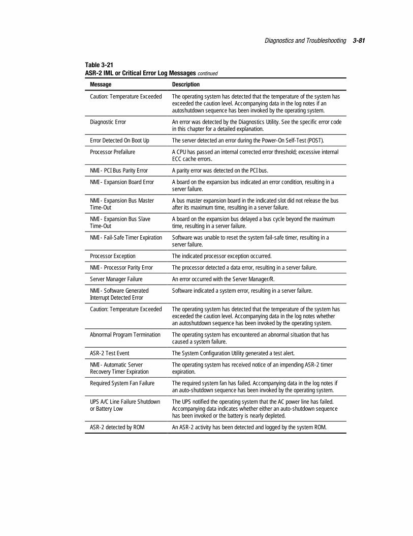
Diagnostics and Troubleshooting 3-81
Table 3-21ASR-2 IML or Critical Error Log Messages continued
Message Description
Caution: Temperature Exceeded The operating system has detected that the temperature of the system hasexceeded the caution level. Accompanying data in the log notes if anautoshutdown sequence has been invoked by the operating system.
Diagnostic Error An error was detected by the Diagnostics Utility. See the specific error codein this chapter for a detailed explanation.
Error Detected On Boot Up The server detected an error during the Power-On Self-Test (POST).
Processor Prefailure A CPU has passed an internal corrected error threshold; excessive internalECC cache errors.
NMI - PCI Bus Parity Error A parity error was detected on the PCI bus.
NMI - Expansion Board Error A board on the expansion bus indicated an error condition, resulting in aserver failure.
NMI - Expansion Bus MasterTime-Out
A bus master expansion board in the indicated slot did not release the busafter its maximum time, resulting in a server failure.
NMI - Expansion Bus SlaveTime-Out
A board on the expansion bus delayed a bus cycle beyond the maximumtime, resulting in a server failure.
NMI - Fail-Safe Timer Expiration Software was unable to reset the system fail-safe timer, resulting in aserver failure.
Processor Exception The indicated processor exception occurred.
NMI - Processor Parity Error The processor detected a data error, resulting in a server failure.
Server Manager Failure An error occurred with the Server Manager/R.
NMI - Software GeneratedInterrupt Detected Error
Software indicated a system error, resulting in a server failure.
Caution: Temperature Exceeded The operating system has detected that the temperature of the system hasexceeded the caution level. Accompanying data in the log notes whetheran autoshutdown sequence has been invoked by the operating system.
Abnormal Program Termination The operating system has encountered an abnormal situation that hascaused a system failure.
ASR-2 Test Event The System Configuration Utility generated a test alert.
NMI - Automatic ServerRecovery Timer Expiration
The operating system has received notice of an impending ASR-2 timerexpiration.
Required System Fan Failure The required system fan has failed. Accompanying data in the log notes ifan auto-shutdown sequence has been invoked by the operating system.
UPS A/C Line Failure Shutdownor Battery Low
The UPS notified the operating system that the AC power line has failed.Accompanying data indicates whether either an auto-shutdown sequencehas been invoked or the battery is nearly depleted.
ASR-2 detected by ROM An ASR-2 activity has been detected and logged by the system ROM.
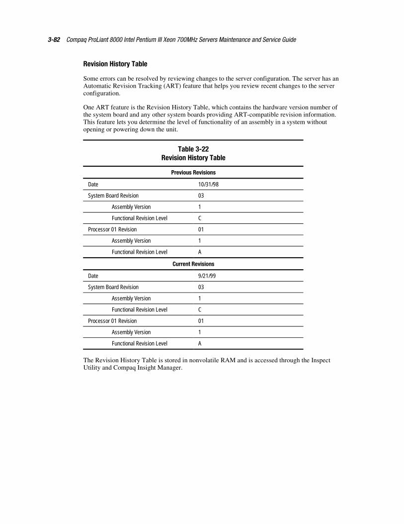
3-82 Compaq ProLiant 8000 Intel Pentium III Xeon 700MHz Servers Maintenance and Service Guide
Revision History Table
Some errors can be resolved by reviewing changes to the server configuration. The server has anAutomatic Revision Tracking (ART) feature that helps you review recent changes to the serverconfiguration.
One ART feature is the Revision History Table, which contains the hardware version number ofthe system board and any other system boards providing ART-compatible revision information.This feature lets you determine the level of functionality of an assembly in a system withoutopening or powering down the unit.
Table 3-22Revision History Table
Previous Revisions
Date 10/31/98
System Board Revision 03
Assembly Version 1
Functional Revision Level C
Processor 01 Revision 01
Assembly Version 1
Functional Revision Level A
Current Revisions
Date 9/21/99
System Board Revision 03
Assembly Version 1
Functional Revision Level C
Processor 01 Revision 01
Assembly Version 1
Functional Revision Level A
The Revision History Table is stored in nonvolatile RAM and is accessed through the InspectUtility and Compaq Insight Manager.
Diagnostics and Troubleshooting 3-83
Storage Fault Recovery Tracking
This feature tracks more than 12 failure-indication parameters, such as timeouts, spin-up, andself-test errors of SCSI drives. You can use these parameters to pinpoint failed storagesubsystem components and to recover from controller or hard drive failure.
Storage Automatic Reconstruction
This feature automatically reconstructs data to an online spare or to a replaced drive if a drivefails. To use the reconstruction feature, you must configure the server for drive mirroring or dataguarding. The reconstruction decreases system downtime by allowing rapid recovery to fullsystem operation if a drive fails.
Network Interface Fault Recovery Tracking
This feature tracks more than 20 failure indication parameters, such as alignment errors, lostframes, and frame copy errors, of Ethernet and Token Ring network interfaces. It decreasesnetwork downtime by enabling diagnosis of network interface failures.
Memory Fault Recovery Tracking
This feature inspects the operation of the memory subsystem looking for uncorrectable memoryerrors.
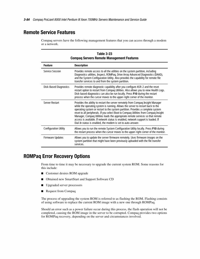
3-84 Compaq ProLiant 8000 Intel Pentium III Xeon 700MHz Servers Maintenance and Service Guide
Remote Service FeaturesCompaq servers have the following management features that you can access through a modemor a network.
Table 3-23Compaq Servers Remote Management Features
Feature Description
Service Session Provides remote access to all the utilities on the system partition, includingDiagnostics utilities, Inspect, ROMPaq, Drive Array Advanced Diagnostics (DAAD),and the System Configuration Utility. Also provides the capability for remote filetransfer services to and from the system partition.
Disk-Based Diagnostics Provides remote diagnostic capability after you configure ASR-2 and the resetrestart option to restart from Compaq Utilities. Also allows you to view Health Logs.Disk-based diagnostics can also be run locally. Press F10 during the restartprocess when the cursor moves to the upper-right corner of the monitor.
Server Restart Provides the ability to restart the server remotely from Compaq Insight Managerwhile the operating system is running. Allows the server to restart back to theoperating system or restart to the system partition. Provides a complete systemreset to all peripherals. If you select Boot to Compaq Utilities from Compaq InsightManager, Compaq Utilities loads the appropriate remote services so that remoteaccess is available. If network status is enabled, network support is loaded. IfDial-In status is enabled, the modem is set to auto-answer.
Configuration Utility Allows you to run the remote System Configuration Utility locally. Press F10 duringthe restart process when the cursor moves to the upper-right corner of the monitor.
Firmware Updates Allows you to update the server firmware remotely. Uses firmware images on thesystem partition that might have been previously uploaded with the file transferservices.
ROMPaq Error Recovery OptionsFrom time to time it may be necessary to upgrade the current system ROM. Some reasons forthis include:
� Customer desires ROM upgrade
� Obtained new SmartStart and Support Software CD
� Upgraded server processors
� Request from Compaq
The process of upgrading the system ROM is referred to as flashing the ROM. Flashing consistsof using software to replace the current ROM image with a new one through ROMPaq.
Should an error such as a power failure occur during this process, the flash operation will not becompleted, causing the ROM image in the server to be corrupted. Compaq provides two optionsfor ROMPaq recovery, depending on the server and circumstances involved.
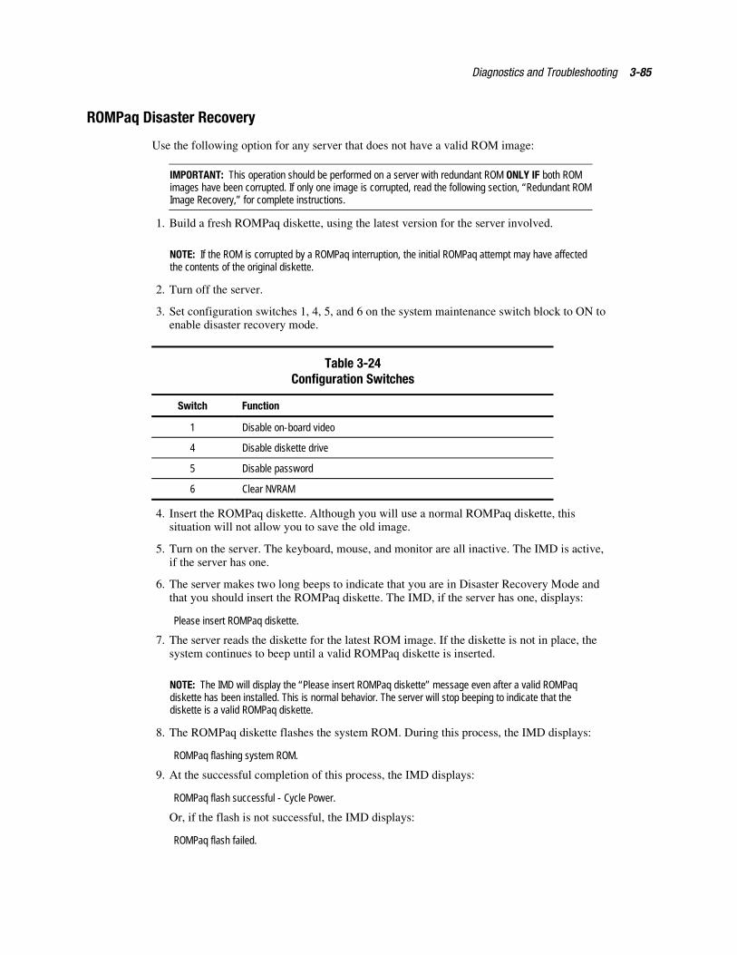
Diagnostics and Troubleshooting 3-85
ROMPaq Disaster Recovery
Use the following option for any server that does not have a valid ROM image:
IMPORTANT: This operation should be performed on a server with redundant ROM ONLY IF both ROMimages have been corrupted. If only one image is corrupted, read the following section, “Redundant ROMImage Recovery,” for complete instructions.
1. Build a fresh ROMPaq diskette, using the latest version for the server involved.
NOTE: If the ROM is corrupted by a ROMPaq interruption, the initial ROMPaq attempt may have affectedthe contents of the original diskette.
2. Turn off the server.
3. Set configuration switches 1, 4, 5, and 6 on the system maintenance switch block to ON toenable disaster recovery mode.
Table 3-24Configuration Switches
Switch Function
1 Disable on-board video
4 Disable diskette drive
5 Disable password
6 Clear NVRAM
4. Insert the ROMPaq diskette. Although you will use a normal ROMPaq diskette, thissituation will not allow you to save the old image.
5. Turn on the server. The keyboard, mouse, and monitor are all inactive. The IMD is active,if the server has one.
6. The server makes two long beeps to indicate that you are in Disaster Recovery Mode andthat you should insert the ROMPaq diskette. The IMD, if the server has one, displays:
Please insert ROMPaq diskette.
7. The server reads the diskette for the latest ROM image. If the diskette is not in place, thesystem continues to beep until a valid ROMPaq diskette is inserted.
NOTE: The IMD will display the “Please insert ROMPaq diskette” message even after a valid ROMPaqdiskette has been installed. This is normal behavior. The server will stop beeping to indicate that thediskette is a valid ROMPaq diskette.
8. The ROMPaq diskette flashes the system ROM. During this process, the IMD displays:
ROMPaq flashing system ROM.
9. At the successful completion of this process, the IMD displays:
ROMPaq flash successful - Cycle Power.
Or, if the flash is not successful, the IMD displays:
ROMPaq flash failed.
3-86 Compaq ProLiant 8000 Intel Pentium III Xeon 700MHz Servers Maintenance and Service Guide
10. After successful completion of this process:
a. Turn off the server.
b. Reset configuration switches 1, 4, 5, and 6. Refer to the Configuration Switches tablewithin this section.
c. Turn on the server as usual.
IMPORTANT: If you are performing this procedure on a server with redundant ROM, where both ROMimages have been corrupted, repeat the process in succession (once for each corrupt image). If only oneimage is corrupt, read the following section, “Redundant ROM Image Recovery,” for completeinstructions.
After a failed ROMPaq, power down the server and repeat the above process.
Redundant ROM Image Recovery
If power is interrupted during the flash process on a server that has redundant ROM, the servershould come up as usual (on the same image that it booted) but the inactive (redundant) ROMimage will be corrupt.
A POST error message displays:
105 – Current System ROM is corrupt – now booting redundant System ROM
In this situation, you are required to flash again so that the invalid image is now valid. After youflash the invalid image, the system will boot to that image, which was the original objective.

Diagnostics and Troubleshooting 3-87
Compaq Insight ManagerCompaq Insight Manager is the Compaq application for easily managing network devices.Compaq Insight Manager delivers intelligent monitoring and alerting as well as visual control ofthe servers.
In Compaq servers, every hardware subsystem, such as disk storage, system memory, andsystem processor, has a robust set of management capabilities. Compaq Full-Spectrum FaultManagement prevents faults before they happen, keeps the system up and running in theunlikely event of a failure, and delivers rapid server recovery to normal operation after a fault.
Features of Compaq Insight Management
Compaq Insight Management features include:
� Web browser access—provides Insight Manager Device and Configuration informationfrom anywhere you have network access and a standard Web browser for Windows NTand NetWare servers.
� Comprehensive fault management—provides management for all major subsystems,including pre-failure alerts in advance of potential system failures.
� Broad configuration management—provides effective deployment and maintenance ofconsistent, manageable configurations with Insight Version Control and Integration ServerMaintenance. Version Control and Integration Server Maintenance allows theadministrator to monitor and update versions of the server and workstation firmware,drivers, and utilities.
� Performance management—sets performance and capacity thresholds for managementvariables related to processor and bus utilization, NIC throughput, logical disk capacity,and more.
� Workstation management—monitors and manages Compaq Professional Workstations.
� Client management—manages faults and assets on Compaq Deskpro computers.
� Netelligent management—receives alarms from Netelligent devices. Full management ofNetelligent devices is supported through integration with Compaq NetelligentManagement Software.
� Asset management—exports asset information from the Compaq Insight Managerdatabase to leading database and spreadsheet applications.
� Remote management—manages in-band or out-of-band devices, online or offline, fromany location.
� Integration with enterprise management platforms—provides integration with leadingmanagement platforms including HP OpenView, IBM NetView, SunNet Manager, andMicrosoft Systems Management Server.
� Full integration with Compaq Remote Insight Board/PCI and ProLiant IntegratedRemote Console—allows “in-band” and “out-of-band” connection for servermanagement to ensure that customers are in touch with their systems, even when they areoffline or without power.
3-88 Compaq ProLiant 8000 Intel Pentium III Xeon 700MHz Servers Maintenance and Service Guide
� SNMP standards—allow integration with other management products.
� Flexible network conductivity—supports multiple transport protocols including IPX,TCP/IP, and PPP to operator over LANs, WANs, and modems.
� Support for these operating systems:
� Microsoft Windows 2000, Microsoft Windows NT
� Novell NetWare, intranetWare and intranetWare for Small Business
� SCO UNIX, OpenServer, and UnixWare
� IBM OS/2 Warp family of products
� Reporting—using Automatic Data Collection, gathers historic performance informationfor graphing or export purposes.
Compaq Insight Management Software Architecture
The Compaq Insight Management software architecture is typical of other network managementsolutions. It has a client/server architecture and is composed of agent software (Compaq InsightManagement Agents) and the management application software (Compaq Insight Manager).
Insight Management Agents
Insight Agents operate on Compaq systems (such as servers and workstations), performing in-depth monitoring of the system’s state by collecting and measuring system parameters. Theseparameters indicate the current state of subsystems by counting the occurrence of particularevents (for example, the number of read operations performed on a disk drive) or monitoring thestate of a critical function (such as whether the cooling fan is operating).
Insight Desktop Agents operate on Compaq Deskpro computers, monitoring functions thatinclude temperature sensing and disk pre-failure alerting.
Insight Agents provide information to management applications, such as Compaq InsightManager, and can generate alarm notifications if significant changes occur in the fault orperformance aspects of system operation. Information is delivered to and from the InsightAgents by the industry-standard Simple Network Management Protocol (SNMP).
Compaq Insight Manager
Compaq Insight Manager delivers intelligent monitoring and alerting as well as visual control ofthe Compaq hardware. In the unlikely event of hardware failures, Compaq Insight Manager alsoprovides a full complement of remote maintenance and control facilities.
For additional information, refer to the online Compaq Insight Manager User Guide on theserver documentation CD that accompanied the server.
Chapter 4Connectors, Switches, and Status
Indicators
ConnectorsThis section shows connector locations on the rear panel, I/O board, and the processor board forthe Compaq ProLiant 8000 servers.
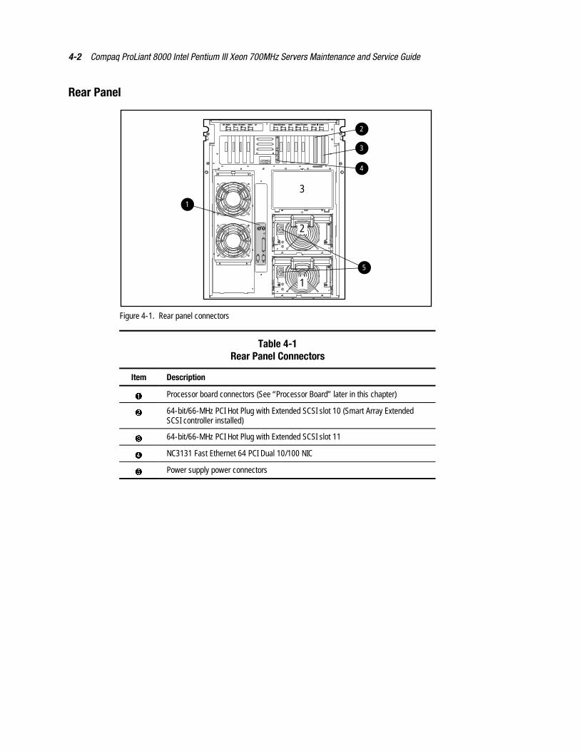
4-2 Compaq ProLiant 8000 Intel Pentium III Xeon 700MHz Servers Maintenance and Service Guide
Rear Panel
1
2
31
3
2
4
5
Figure 4-1. Rear panel connectors
Table 4-1Rear Panel Connectors
Item Description
� Processor board connectors (See “Processor Board” later in this chapter)
� 64-bit/66-MHz PCI Hot Plug with Extended SCSI slot 10 (Smart Array ExtendedSCSI controller installed)
� 64-bit/66-MHz PCI Hot Plug with Extended SCSI slot 11
� NC3131 Fast Ethernet 64 PCI Dual 10/100 NIC
� Power supply power connectors
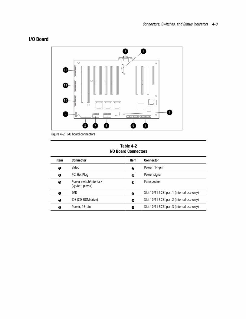
Connectors, Switches, and Status Indicators 4-3
I/O Board
12
11
10
1
9
45678
2
3
Figure 4-2. I/O board connectors
Table 4-2I/O Board Connectors
Item Connector Item Connector
� Video � Power, 14-pin
� PCI Hot Plug � Power signal
� Power switch/interlock(system power)
� Fan/speaker
� IMD Slot 10/11 SCSI port 1 (internal use only)
� IDE (CD-ROM drive) Slot 10/11 SCSI port 2 (internal use only)
� Power, 16-pin � Slot 10/11 SCSI port 3 (internal use only)
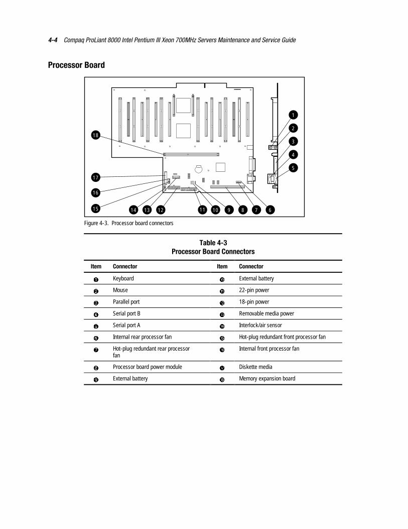
4-4 Compaq ProLiant 8000 Intel Pentium III Xeon 700MHz Servers Maintenance and Service Guide
Processor Board
914 1213 11 10 78 6
1
2
3
4
5
15
18
17
16
Figure 4-3. Processor board connectors
Table 4-3Processor Board Connectors
Item Connector Item Connector
� Keyboard External battery
� Mouse 22-pin power
� Parallel port � 18-pin power
� Serial port B Removable media power
� Serial port A � Interlock/air sensor
� Internal rear processor fan � Hot-plug redundant front processor fan
� Hot-plug redundant rear processorfan
� Internal front processor fan
� Processor board power module � Diskette media
� External battery � Memory expansion board
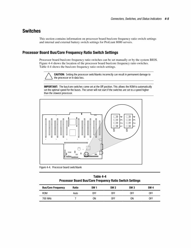
Connectors, Switches, and Status Indicators 4-5
SwitchesThis section contains information on processor board bus/core frequency ratio switch settingsand internal and external battery switch settings for ProLiant 8000 servers.
Processor Board Bus/Core Frequency Ratio Switch Settings
Processor board bus/core frequency ratio switches can be set manually or by the system BIOS.Figure 4-4 shows the location of the processor board bus/core frequency ratio switches.Table 4-4 shows the bus/core frequency ratio switch settings.
CAUTION: Setting the processor switchbanks incorrectly can result in permanent damage tothe processor or in data loss.
IMPORTANT: The bus/core switches come set at the Off position. This allows the ROM to automaticallyset the optimal speed for the buses. The server will not start if the switches are set to a speed higherthan the slowest processor.
1
on
23
4
1
on
23
4
Figure 4-4. Processor board switchbank
Table 4-4Processor Board Bus/Core Frequency Ratio Switch Settings
Bus/Core Frequency Ratio SW 1 SW 2 SW 3 SW 4
ROM Auto OFF OFF OFF OFF
700 MHz 7 ON OFF ON OFF
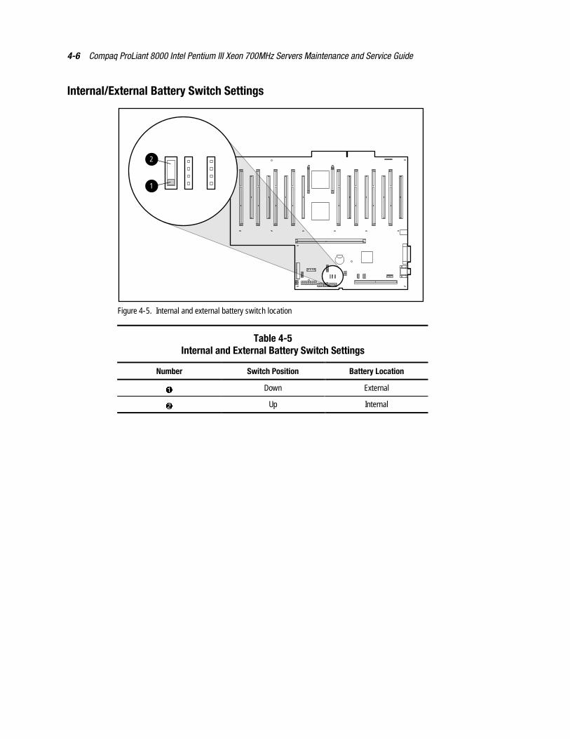
4-6 Compaq ProLiant 8000 Intel Pentium III Xeon 700MHz Servers Maintenance and Service Guide
Internal/External Battery Switch Settings
2
1
Figure 4-5. Internal and external battery switch location
Table 4-5Internal and External Battery Switch Settings
Number Switch Position Battery Location
� Down External
� Up Internal
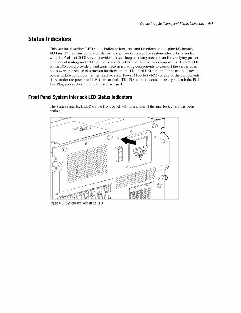
Connectors, Switches, and Status Indicators 4-7
Status IndicatorsThis section describes LED status indicator locations and functions on hot-plug I/O boards,I/O fans, PCI expansion boards, drives, and power supplies. The system interlocks providedwith the ProLiant 8000 server provide a closed-loop checking mechanism for verifying propercomponent mating and cabling interconnects between critical server components. Three LEDson the I/O board provide visual assistance in isolating components to check if the server doesnot power up because of a broken interlock chain. The third LED on the I/O board indicates apower failure condition—either the Processor Power Module (VRM) or any of the componentslisted under the power-fail LEDs are at fault. The I/O board is located directly beneath the PCIHot Plug access doors on the top access panel.
Front Panel System Interlock LED Status Indicators
The system interlock LED on the front panel will turn amber if the interlock chain has beenbroken.
Figure 4-6. System interlock status LED
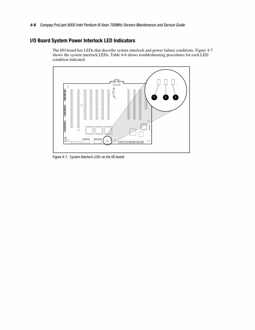
4-8 Compaq ProLiant 8000 Intel Pentium III Xeon 700MHz Servers Maintenance and Service Guide
I/O Board System Power Interlock LED Indicators
The I/O board has LEDs that describe system interlock and power failure conditions. Figure 4-7shows the system interlock LEDs. Table 4-6 shows troubleshooting procedures for each LEDcondition indicated.
321
Figure 4-7. System Interlock LEDs on the I/O board
Connectors, Switches, and Status Indicators 4-9
Table 4-6System Interlock LED Indicators on I/O Board
Possible Affected Components to Check
InterlockPower
(Aux 5V)Power
FailSystem
Interlock
� � �
None (system operational) ON OFF OFF
If the server does not power up:
1. Reinsert the power supply.
2. Place the Power On/Standby switch to ON.
3. Verify that the power supply status LED blinks green for10 to 20 seconds and then is solid green when the serverpowers up.
4. If the Power Supply Status LED stays dark (does notblink), verify that the I/O board power cable is connectedat the I/O board and the power backplane.
Power switch cables ON OFF ON
I/O-to-processor board connection
Processor board components
Processor Power Modules ON ON OFF
Power supplies
Power cables
Note: If the System Interlock LED is on, check the processor board LEDs to isolate the failure point.
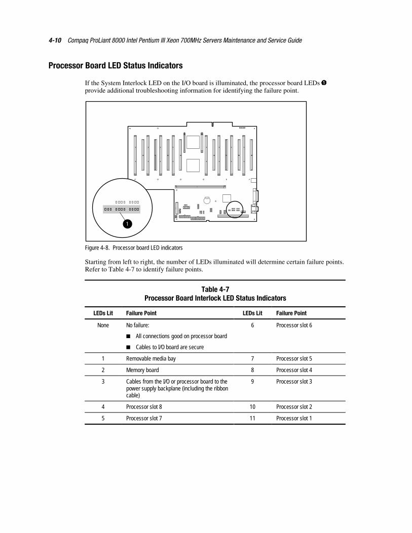
4-10 Compaq ProLiant 8000 Intel Pentium III Xeon 700MHz Servers Maintenance and Service Guide
Processor Board LED Status Indicators
If the System Interlock LED on the I/O board is illuminated, the processor board LEDs �provide additional troubleshooting information for identifying the failure point.
1
Figure 4-8. Processor board LED indicators
Starting from left to right, the number of LEDs illuminated will determine certain failure points.Refer to Table 4-7 to identify failure points.
Table 4-7Processor Board Interlock LED Status Indicators
LEDs Lit Failure Point LEDs Lit Failure Point
None No failure: 6 Processor slot 6
� All connections good on processor board
� Cables to I/O board are secure
1 Removable media bay 7 Processor slot 5
2 Memory board 8 Processor slot 4
3 Cables from the I/O or processor board to thepower supply backplane (including the ribboncable)
9 Processor slot 3
4 Processor slot 8 10 Processor slot 2
5 Processor slot 7 11 Processor slot 1
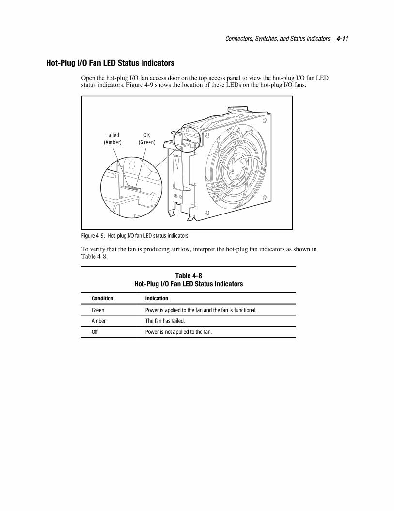
Connectors, Switches, and Status Indicators 4-11
Hot-Plug I/O Fan LED Status Indicators
Open the hot-plug I/O fan access door on the top access panel to view the hot-plug I/O fan LEDstatus indicators. Figure 4-9 shows the location of these LEDs on the hot-plug I/O fans.
OK(Green)
Failed(Amber)
Figure 4-9. Hot-plug I/O fan LED status indicators
To verify that the fan is producing airflow, interpret the hot-plug fan indicators as shown inTable 4-8.
Table 4-8Hot-Plug I/O Fan LED Status Indicators
Condition Indication
Green Power is applied to the fan and the fan is functional.
Amber The fan has failed.
Off Power is not applied to the fan.
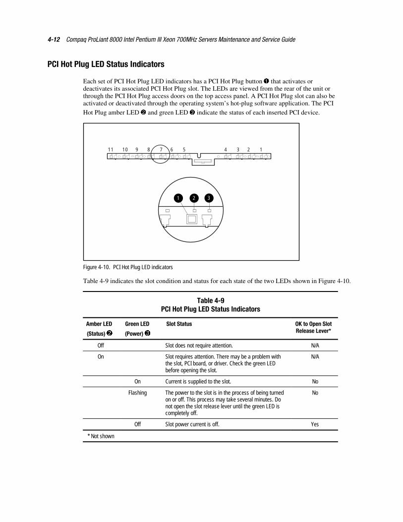
4-12 Compaq ProLiant 8000 Intel Pentium III Xeon 700MHz Servers Maintenance and Service Guide
PCI Hot Plug LED Status Indicators
Each set of PCI Hot Plug LED indicators has a PCI Hot Plug button � that activates ordeactivates its associated PCI Hot Plug slot. The LEDs are viewed from the rear of the unit orthrough the PCI Hot Plug access doors on the top access panel. A PCI Hot Plug slot can also beactivated or deactivated through the operating system’s hot-plug software application. The PCI
Hot Plug amber LED � and green LED � indicate the status of each inserted PCI device.
1
11 10 56789 1234
32
Figure 4-10. PCI Hot Plug LED indicators
Table 4-9 indicates the slot condition and status for each state of the two LEDs shown in Figure 4-10.
Table 4-9PCI Hot Plug LED Status Indicators
Amber LED
(Status) �
Green LED
(Power) �
Slot Status OK to Open SlotRelease Lever*
Off Slot does not require attention. N/A
On Slot requires attention. There may be a problem withthe slot, PCI board, or driver. Check the green LEDbefore opening the slot.
N/A
On Current is supplied to the slot. No
Flashing The power to the slot is in the process of being turnedon or off. This process may take several minutes. Donot open the slot release lever until the green LED iscompletely off.
No
Off Slot power current is off. Yes
* Not shown
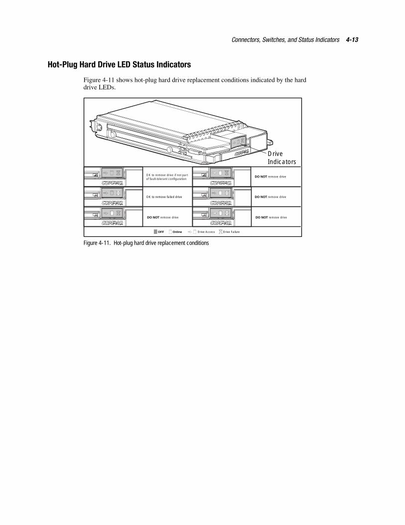
Connectors, Switches, and Status Indicators 4-13
Hot-Plug Hard Drive LED Status Indicators
Figure 4-11 shows hot-plug hard drive replacement conditions indicated by the harddrive LEDs.
Drive Indicators
OnlineOFF Drive Access Drive Failure
OK to remove drive if not partof fault-tolerant configuration
OK to remove failed drive
DO NOT remove drive
DO NOT remove drive
DO NOT remove drive
DO NOT remove drive
Figure 4-11. Hot-plug hard drive replacement conditions
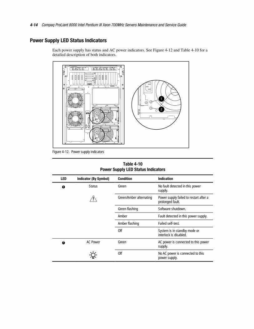
4-14 Compaq ProLiant 8000 Intel Pentium III Xeon 700MHz Servers Maintenance and Service Guide
Power Supply LED Status Indicators
Each power supply has status and AC power indicators. See Figure 4-12 and Table 4-10 for adetailed description of both indicators.
1
2
Figure 4-12. Power supply indicators
Table 4-10Power Supply LED Status Indicators
LED Indicator (By Symbol) Condition Indication
� Status Green No fault detected in this powersupply.
Green/Amber alternating Power supply failed to restart after aprolonged fault.
Green flashing Software shutdown.
Amber Fault detected in this power supply.
Amber flashing Failed self-test.
Off System is in standby mode orinterlock is disabled.
� AC Power Green AC power is connected to this powersupply.
Off No AC power is connected to thispower supply.
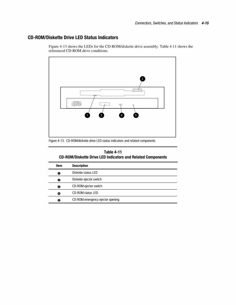
Connectors, Switches, and Status Indicators 4-15
CD-ROM/Diskette Drive LED Status Indicators
Figure 4-13 shows the LEDs for the CD-ROM/diskette drive assembly. Table 4-11 shows thereferenced CD-ROM drive conditions.
COMPACT
31 4 5
2
Figure 4-13. CD-ROM/diskette drive LED status indicators and related components
Table 4-11CD-ROM/Diskette Drive LED Indicators and Related Components
Item Description
� Diskette status LED
� Diskette ejector switch
� CD-ROM ejector switch
� CD-ROM status LED
� CD-ROM emergency ejector opening
Chapter 5Specifications
This section provides operating and performance specifications for Compaq ProLiant 8000servers.
� System unit
� Power supply
� Dual Inline Memory Module
� 1.44-MB diskette drive
� IDE Max Slimline CD-ROM Drive
� Hot-plug Ultra2 SCSI hard drives
� Hot-plug Ultra3 SCSI hard drives
� Smart Array 4250ES Controller
� NC3131 Fast Ethernet 64 PCI Dual 10/100 Controller
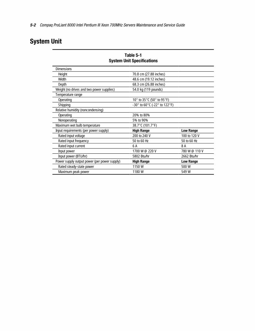
5-2 Compaq ProLiant 8000 Intel Pentium III Xeon 700MHz Servers Maintenance and Service Guide
System Unit
Table 5-1System Unit Specifications
DimensionsHeight 70.8 cm (27.88 inches)Width 48.6 cm (19.12 inches)Depth 68.3 cm (26.88 inches)
Weight (no drives and two power supplies) 54.0 kg (119 pounds)Temperature range
Operating 10° to 35°C (50° to 95°F)Shipping -30° to 60°C (-22° to 122°F)
Relative humidity (noncondensing)Operating 20% to 80%Nonoperating 5% to 90%
Maximum wet bulb temperature 38.7°C (101.7°F)Input requirements (per power supply) High Range Low Range
Rated input voltage 200 to 240 V 100 to 120 VRated input frequency 50 to 60 Hz 50 to 60 HzRated input current 6 A 8 AInput power 1700 W @ 220 V 780 W @ 110 VInput power (BTU/hr) 5802 Btu/hr 2662 Btu/hr
Power supply output power (per power supply) High Range Low RangeRated steady-state power 1150 W 500 WMaximum peak power 1180 W 549 W
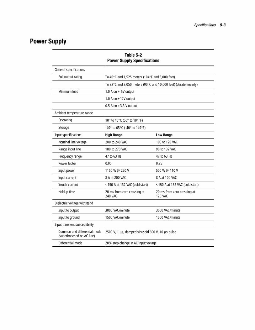
Specifications 5-3
Power Supply
Table 5-2Power Supply Specifications
General specifications
Full output rating To 40°C and 1,525 meters (104°F and 5,000 feet)
To 32°C and 3,050 meters (90°C and 10,000 feet) (derate linearly)
Minimum load 1.0 A on + 5V output
1.0 A on +12V output
0.5 A on +3.3 V output
Ambient temperature range
Operating 10° to 40°C (50° to 104°F)
Storage -40° to 65°C (-40° to 149°F)
Input specifications High Range Low Range
Nominal line voltage 200 to 240 VAC 100 to 120 VAC
Range input line 180 to 270 VAC 90 to 132 VAC
Frequency range 47 to 63 Hz 47 to 63 Hz
Power factor 0.95 0.95
Input power 1150 W @ 220 V 500 W @ 110 V
Input current 8 A at 200 VAC 8 A at 100 VAC
Inrush current <150 A at 132 VAC (cold start) <150 A at 132 VAC (cold start)
Holdup time 20 ms from zero crossing at240 VAC
20 ms from zero crossing at120 VAC
Dielectric voltage withstand
Input to output 3000 VAC/minute 3000 VAC/minute
Input to ground 1500 VAC/minute 1500 VAC/minute
Input transient susceptibility
Common and differential mode(superimposed on AC line)
2500 V, 1 µs, damped sinusoid 600 V, 10 µs pulse
Differential mode 20% step change in AC input voltage
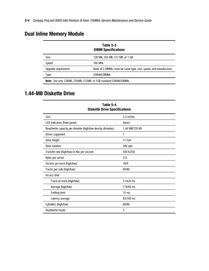
5-4 Compaq ProLiant 8000 Intel Pentium III Xeon 700MHz Servers Maintenance and Service Guide
Dual Inline Memory Module
Table 5-3DIMM Specifications
Size 128 MB, 256 MB, 512 MB, or 1 GB
Speed 100 MHz
Upgrade requirement Bank of 2 DIMMs; must be same type, size, speed, and manufacturer
Type SDRAM DIMMs
Note: Use only 128MB, 256MB, 512MB, or 1GB standard SDRAM DIMMs.
1.44-MB Diskette Drive
Table 5-4Diskette Drive Specifications
Size 3.5 inches
LED indicators (front panel) Green
Read/write capacity per diskette (high/low density diskettes) 1.44 MB/720 KB
Drives supported 1
Drive height 11 mm
Drive rotation 300 rpm
Transfer rate (high/low) in Kbs per second 500 K/250
Bytes per sector 512
Sectors per track (high/low) 18/9
Tracks per side (high/low) 80/80
Access time
Track-to-track (high/low) 3 ms/6 ms
Average (high/low) 174/94 ms
Settling time 15 ms
Latency average 83/100 ms
Cylinders (high/low) 80/80
Read/write heads 2
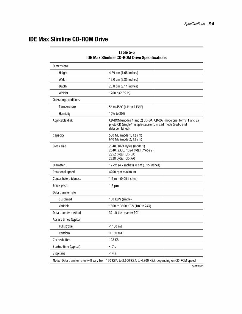
Specifications 5-5
IDE Max Slimline CD-ROM Drive
Table 5-5IDE Max Slimline CD-ROM Drive Specifications
Dimensions
Height 4.29 cm (1.68 inches)
Width 15.0 cm (5.85 inches)
Depth 20.8 cm (8.11 inches)
Weight 1200 g (2.65 lb)
Operating conditions
Temperature 5° to 45°C (41° to 113°F)
Humidity 10% to 80%
Applicable disk CD-ROM (modes 1 and 2) CD-DA, CD-XA (mode one, forms 1 and 2),photo CD (single/multiple-session), mixed mode (audio anddata combined)
Capacity 550 MB (mode 1, 12 cm)640 MB (mode 2, 12 cm)
Block size 2048, 1024 bytes (mode 1)2340, 2336, 1024 bytes (mode 2)2352 bytes (CD-DA)2328 bytes (CD-XA)
Diameter 12 cm (4.7 inches), 8 cm (3.15 inches)
Rotational speed 4200 rpm maximum
Center hole thickness 1.2 mm (0.05 inches)
Track pitch 1.6 µm
Data transfer rate
Sustained 150 KB/s (single)
Variable 1500 to 3600 KB/s (10X to 24X)
Data transfer method 32-bit bus-master PCI
Access times (typical)
Full stroke < 100 ms
Random < 150 ms
Cache/buffer 128 KB
Startup time (typical) < 7 s
Stop time < 4 s
Note: Data transfer rates will vary from 150 KB/s to 3,600 KB/s to 4,800 KB/s depending on CD-ROM speed.
continued
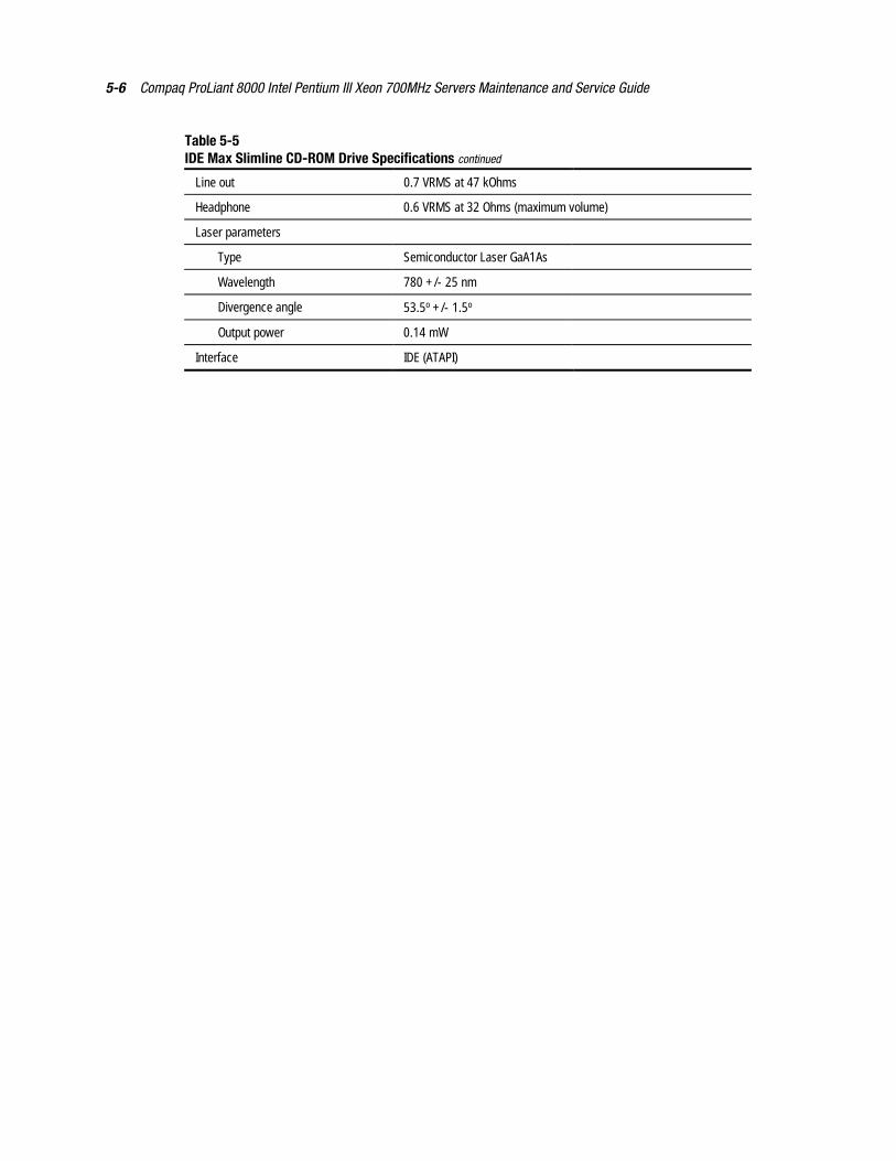
5-6 Compaq ProLiant 8000 Intel Pentium III Xeon 700MHz Servers Maintenance and Service Guide
Table 5-5IDE Max Slimline CD-ROM Drive Specifications continued
Line out 0.7 VRMS at 47 kOhms
Headphone 0.6 VRMS at 32 Ohms (maximum volume)
Laser parameters
Type Semiconductor Laser GaA1As
Wavelength 780 +/- 25 nm
Divergence angle 53.5o +/- 1.5o
Output power 0.14 mW
Interface IDE (ATAPI)
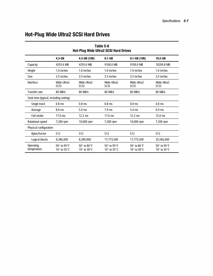
Specifications 5-7
Hot-Plug Wide Ultra2 SCSI Hard Drives
Table 5-6Hot-Plug Wide Ultra2 SCSI Hard Drives
4.3-GB 4.3-GB (10K) 9.1-GB 9.1-GB (10K) 18.2-GB
Capacity 4293.6 MB 4293.6 MB 9100.0 MB 9100.0 MB 18209.8 MB
Height 1.0 inches 1.0 inches 1.0 inches 1.0 inches 1.0 inches
Size 3.5 inches 3.5 inches 3.5 inches 3.5 inches 3.5 inches
Interface Wide-Ultra2SCSI
Wide-Ultra2SCSI
Wide-Ultra2SCSI
Wide-Ultra2SCSI
Wide-Ultra2SCSI
Transfer rate 80 MB/s 80 MB/s 80 MB/s 80 MB/s 80 MB/s
Seek time (typical, including setting)
Single track 0.8 ms 0.8 ms 0.8 ms 0.8 ms 0.8 ms
Average 8.8 ms 5.4 ms 7.9 ms 5.4 ms 6.9 ms
Full stroke 17.0 ms 12.2 ms 17.0 ms 12.2 ms 15.0 ms
Rotational speed 7,200 rpm 10,000 rpm 7,200 rpm 10,000 rpm 7,200 rpm
Physical configuration
Bytes/Sector 512 512 512 512 512
Logical blocks 8,386,000 8,389,000 17,773,500 17,773,500 35,566,000
Operatingtemperature
50° to 95°F10° to 35°C
50° to 86°F10° to 30°C
50° to 95°F10° to 35°C
50° to 86°F10° to 30°C
50° to 95°F10° to 35°C
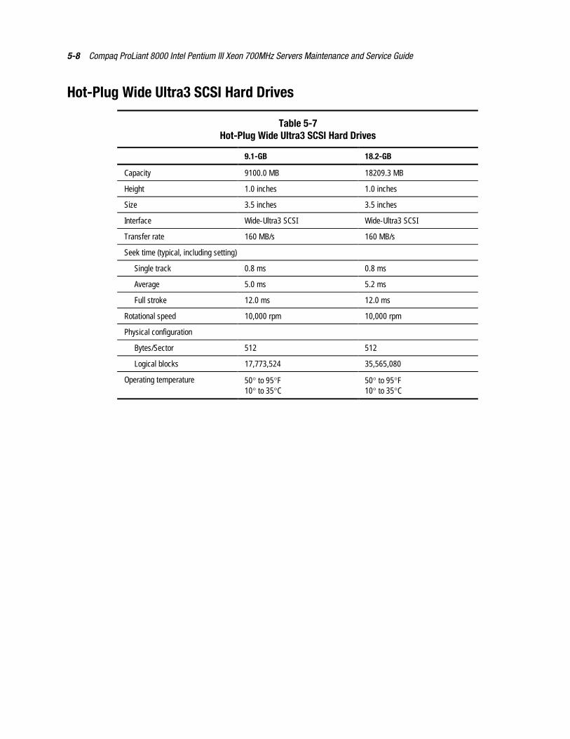
5-8 Compaq ProLiant 8000 Intel Pentium III Xeon 700MHz Servers Maintenance and Service Guide
Hot-Plug Wide Ultra3 SCSI Hard Drives
Table 5-7Hot-Plug Wide Ultra3 SCSI Hard Drives
9.1-GB 18.2-GB
Capacity 9100.0 MB 18209.3 MB
Height 1.0 inches 1.0 inches
Size 3.5 inches 3.5 inches
Interface Wide-Ultra3 SCSI Wide-Ultra3 SCSI
Transfer rate 160 MB/s 160 MB/s
Seek time (typical, including setting)
Single track 0.8 ms 0.8 ms
Average 5.0 ms 5.2 ms
Full stroke 12.0 ms 12.0 ms
Rotational speed 10,000 rpm 10,000 rpm
Physical configuration
Bytes/Sector 512 512
Logical blocks 17,773,524 35,565,080
Operating temperature 50° to 95°F10° to 35°C
50° to 95°F10° to 35°C
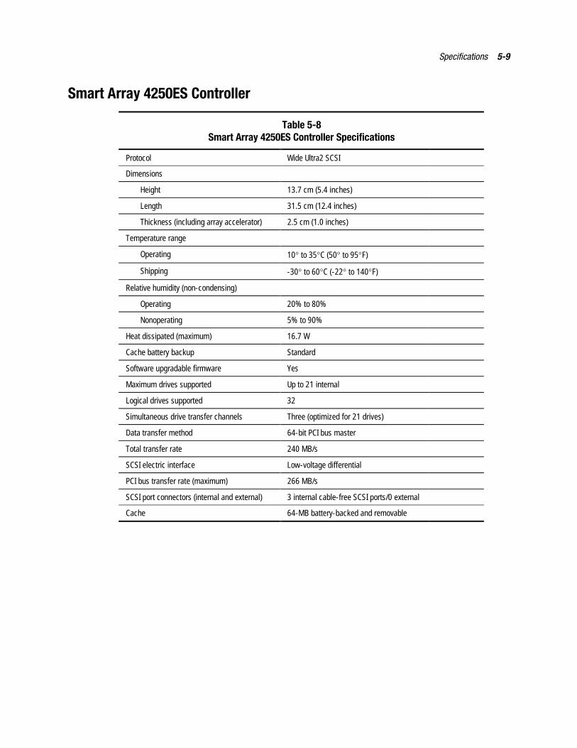
Specifications 5-9
Smart Array 4250ES Controller
Table 5-8Smart Array 4250ES Controller Specifications
Protocol Wide Ultra2 SCSI
Dimensions
Height 13.7 cm (5.4 inches)
Length 31.5 cm (12.4 inches)
Thickness (including array accelerator) 2.5 cm (1.0 inches)
Temperature range
Operating 10° to 35°C (50° to 95°F)
Shipping -30° to 60°C (-22° to 140°F)
Relative humidity (non-condensing)
Operating 20% to 80%
Nonoperating 5% to 90%
Heat dissipated (maximum) 16.7 W
Cache battery backup Standard
Software upgradable firmware Yes
Maximum drives supported Up to 21 internal
Logical drives supported 32
Simultaneous drive transfer channels Three (optimized for 21 drives)
Data transfer method 64-bit PCI bus master
Total transfer rate 240 MB/s
SCSI electric interface Low-voltage differential
PCI bus transfer rate (maximum) 266 MB/s
SCSI port connectors (internal and external) 3 internal cable-free SCSI ports/0 external
Cache 64-MB battery-backed and removable
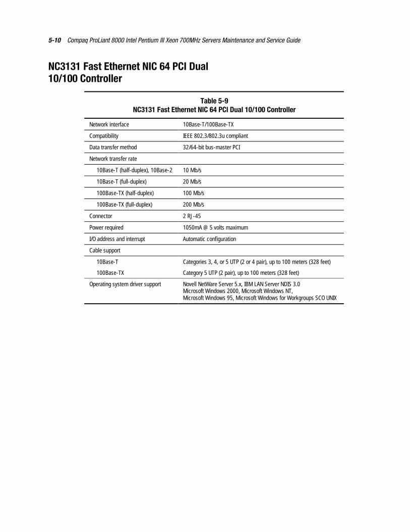
5-10 Compaq ProLiant 8000 Intel Pentium III Xeon 700MHz Servers Maintenance and Service Guide
NC3131 Fast Ethernet NIC 64 PCI Dual10/100 Controller
Table 5-9NC3131 Fast Ethernet NIC 64 PCI Dual 10/100 Controller
Network interface 10Base-T/100Base-TX
Compatibility IEEE 802.3/802.3u compliant
Data transfer method 32/64-bit bus-master PCI
Network transfer rate
10Base-T (half-duplex), 10Base-2 10 Mb/s
10Base-T (full-duplex) 20 Mb/s
100Base-TX (half-duplex) 100 Mb/s
100Base-TX (full-duplex) 200 Mb/s
Connector 2 RJ-45
Power required 1050mA @ 5 volts maximum
I/O address and interrupt Automatic configuration
Cable support
10Base-T Categories 3, 4, or 5 UTP (2 or 4 pair), up to 100 meters (328 feet)
100Base-TX Category 5 UTP (2 pair), up to 100 meters (328 feet)
Operating system driver support Novell NetWare Server 5.x, IBM LAN Server NDIS 3.0Microsoft Windows 2000, Microsoft Windows NT,Microsoft Windows 95, Microsoft Windows for Workgroups SCO UNIX
Index
AAC power cord, disconnecting 2-27access panels
left sidepart number 1-3removing 2-8removing, illustrated 2-8replacing 2-8
right sidepart number 1-3removing 2-7removing, illustrated 2-7replacing 2-7
toppart number 1-3removing 2-6removing, illustrated 2-6replacing 2-6
ADUaccessing 3-5caution 3-44description 3-3, 3-44diagnostic messages 3-45executing 3-6starting 3-44
ADU diagnostic messagestable 3-45
air bafflesfront
removing 2-10removing, illustrated 2-10replacing 2-10
main processorremoving 2-12removing, illustrated 2-12replacing 2-12
rearremoving 2-11removing, illustrated 2-11replacing 2-11
airflow caution 2-34Array Configuration Utility
accessing 3-5, 3-6executing 3-6
array controllerreleasing, illustrated 2-67removing 2-67removing, illustrated 2-68replacing 2-69replacing, illustrated 2-69
Array Diagnostic Utility See ADUART, assembly version 3-82ASR-2
allowing network access 3-76attended recovery 3-71booting into Compaq
Utilities 3-76booting into operating
system 3-78configuring 3-70, 3-74Critical Error Log
messages 3-80default value 3-74description 3-70features 3-73flow chart 3-75for off-site servers 3-74for remote servers 3-74hardware requirements 3-72Integrated Management Log
messages 3-80operating system restart SCU
Setting, table 3-79paging administrator 3-70restart setting
dial-in status 3-79dial-out status 3-79dial-out string 3-79network card slot 3-79network controller 3-79network frame type 3-79network host name 3-79network IP address 3-79
2 Compaq ProLiant 8000 Intel Pentium III Xeon 700MHz Servers Maintenance and Service Guide
network IP net mask 3-79network IP router
address 3-79network protocol 3-79network status 3-79serial interface 3-79
security 3-79software error
recovery 3-73recovery boot option 3-73recovery timeout 3-73
standby recoveryserver option 3-73server port 3-73time-out 3-73
thermal shutdown 3-73timer 3-74unattended recovery 3-71UPS shutdown 3-73
ASR-2 featurestable 3-73
ASR-2 IML log messages See errorlog messages
ASR-2 IML or Critital Error LogMessagestable 3-80
Asset Management, defined 3-87audible beeps, during POST 3-8Automatic Data Collection,
defined 3-88Automatic Revision
Tracking See ARTAutomatic Server
Recovery-2 See ASR-2automatic storage reconstruction,
defined 3-83
Bbackplane board
part number 1-6removing 2-29removing, illustrated 2-29replacing 2-29
baffle kit, part number 1-4basket insulator
removing 2-74removing, illustrated 2-74replacing 2-74
batteryattaching to system board 2-79connectors, identified 4-4disposal
caution 2-79
installing external 2-79installing external,
illustrated 2-79part number 1-6recycling 2-79switch location, illustrated 4-6
beeps, during POST 3-8bezels
front, removing 2-14front, removing, illustrated 2-14front, replacing 2-14
blank bezels caution 2-15blanking panels
caution 2-15expansion board, part
number 1-4hard drive
removing 2-18removing, illustrated 2-18replacing 2-18
power supplyremoving 2-26removing, illustrated 2-26replacing 2-26
removable mediaremoving, illustrated 2-16replacing 2-16
removing 2-16SCSI, part number 1-4
buns, part number 1-7bus/core ratio switch settings
caution 4-5
Ccable grommet, part number 1-3cable kit
power, part number 1-7signal, part number 1-7
cabling diagramsconnecting an array controller
with extended SCSI to drivecage 1, 2, or 3 2-73
connecting the PCI SCSIcontroller board to removablemedia bays 2-72
cacheexamples of processor
mixing 2-48guidelines 2-47installation order 2-47
cache accelerator replacementcaution 2-42
cache acceleratorsidentified 2-42part number 1-8
Index 3
removing 2-43removing, illustrated 2-44replacing 2-44sockets, illustrated 2-42
carton, part number 1-7casters
part number 1-4removing 2-9removing, illustrated 2-9replacing 2-9
CD-ROM drivelaser warning label,
illustrated 2-2part number 1-6removing, illustrated 2-17specifications 5-5test error codes 3-42
CD-ROM drive laserwarning 2-2
CD-ROM ejector switch,identified 4-15
CD-ROM emergency ejectoropening, identified 4-15
CD-ROM status LED,identified 4-15
CD-ROM/Diskette Drive LEDs andRelated Componentstable 4-15
chassis, part number 1-3Client Management, defined 3-87communication parameters,
setting 3-76Compaq Insight Management
features 3-87software architecture 3-88
Compaq Insight Managerdefined 3-65, 3-88description 3-2remote maintenance 3-88viewing the event list 3-66
Compaq Integrated Remote Console,features 3-74
Compaq network interface board testerror codestable 3-41
Compaq Network InterfaceController See NIC
Compaq Servers RemoteManagement Featurestable 3-84
Compaq Survey Utilitydescription 3-2installing 3-2viewing 3-66
Compaq System ConfigurationUtility Pager Settingstable 3-76
Compaq System ReferenceLibrary 3-70
Comprehensive fault management,defined 3-87
configuration switchestable 3-85
conflict, resolving 3-3connectors
diskette media, identified 4-4external battery, identified 4-4fan/speaker, identified 4-3front processor fan,
identified 4-4I/O board, illustrated 4-3I/O board, table 4-3IDE, identified 4-3IMD, identified 4-3interlock/air sensor,
identified 4-4keyboard, identified 4-4memory expansion board,
identified 4-4mouse, identified 4-4NC3131 Fast Ethernet 64 PCI
Dual 10/100 NICidentified 4-2
parallel port, identified 4-4PCI Hot Plug, identified 4-3power supply, identified 4-2power switch/interlock,
identified 4-3power, identified 4-3, 4-4processor board power module,
identified 4-4processor board, identified 4-2,
4-4processor board, table 4-4rear panel 4-1rear panel, illustrated 4-2rear processor fan,
identified 4-4redundant rear processor fan,
identified 4-4removable media power,
identified 4-4SCSI slot 10, identified 4-2SCSI slot 11, identified 4-2SCSI, identified 4-3serial port, identified 4-4video, identified 4-3
4 Compaq ProLiant 8000 Intel Pentium III Xeon 700MHz Servers Maintenance and Service Guide
controller firmware upgradecaution 3-44
controllerscommunication failure 3-47Smart Array
cache 5-9data transfer method 5-9dimensions 5-9logical drives supported 5-9maximum drives
supported 5-9protocol 5-9SCSI port connectors 5-9specifications 5-9
upgrading firmware 3-47Correctable Memory Logs See IMLcountry kit, part number 1-7Critical Error Log See also IML
error messages 3-80recorded information 3-74,
3-76, 3-78, 3-80viewing 3-72, 3-80where stored 3-80
Critical Error Log messages Seealso error log messages
critical fan failure detected 3-8
DDAAD
accessing remotely 3-84description 3-3software location 2-1
data integrity cautions 2-38data loss
caution 2-20, 2-21, 2-25, 2-28,2-67, 2-71, 3-5
default configurationboot messages 3-4determining 3-4
Diagnose Drive Array utility,accessing 3-33
diagnosing problems, harddrives 2-19
Diagnostic toolstable 3-2
Diagnosticsaccessing 3-2, 3-5booting remotely 3-78defined 3-33description 3-2diskette, creating 3-33Drive Array 3-33error codes 3-33locating 3-2overview 3-2
POST error messages 3-8running 3-33software location 2-1test error codes
CD-ROM drive 3-42diskette drive 3-39hard drive 3-41keyboard 3-37memory 3-35modem 3-40NIC 3-41pointing device
interface 3-43processor 3-34SCSI hard drive 3-41SCSI tape drive 3-42SCSI/IDE CD-ROM
drive 3-42serial port 3-40tape drive 3-42video display unit 3-38
Test Error Codes Tables,description 3-33
when to run 3-7Diagnostics CD, booting from 3-4dial-in status, setting 3-77dial-out status, setting 3-77dial-out string, setting 3-77DIMM specifications
table 5-4DIMM upgrade combinations
table 2-37disconnecting all power
warning 2-5disconnecting power from the system
warning 2-3diskette drive
access time 5-4cylinders 5-4disabling 3-85height 5-4identified 2-15read/write heads 5-4removing, illustrated 2-17rotation speed 5-4specifications 5-4test error codes 3-39transfer rate 5-4
diskette drive specificationstable 5-4
diskette drive test error codestable 3-39
diskette ejector switch,identified 4-15
diskette media connector,identified 4-4
Index 5
diskette status LED, identified 4-15diskette, creating Diagnostics 3-33Drive Array Advanced
Diagnostics See DAADdrive array, diagnosing 3-33drive cage blanking panel
part number 1-4drive cage with backplane board
part number 1-3removing 2-21removing, illustrated 2-21replacing 2-21
drive cage with backplane board,capacity 2-15
drivers, installing 3-3
EECC multiple bit error detected in
DIMM 3-8electric shock
warning 2-2, 2-3, 2-5electrical outlets
warning 2-5electrostatic discharge See ESDelectrostatic discharge damage
caution 2-42EMI shield, part number 1-4environmental recovery 3-71equipment damage
caution 2-25, 2-28, 2-48warning 2-2, 2-4, 2-5
equipment handlingwarning 2-2
equipment weightwarning 2-2
Erase Utilitycaution 3-5
error codes See also test error codes101 through 162 3-9101 through 199 3-34105 3-861101 through 1109 3-401155 through 1612 3-171201 through 1210 3-401613 through 1621 3-181622 through 1720 3-19163 through 207 3-101702 3-191721 through 1726 3-201727 through 1750 3-211751 through 1767 3-221768 through 1774 3-231775 through 1776 3-241777 through 1781 3-251782 through 1784 3-26
1785 3-271786 through 1787 3-281788 3-291789 through 1793 3-301794 through 1798 3-311795 through 1799 3-311799 through 1800 3-32200 through 0212-89 3-35208 through 219 3-11214-01 through 215 3-36219 through 304 3-12301 through 304 3-37401 through 498 3-3740X through 611 3-13501 through 516 3-38600 through 699 3-396000 through 6092 3-416500 through 6528 3-416600 through 6608 3-426700 through 6728 3-42800 through 802 3-14803 through 805 3-15806 through 1152 3-168601 3-43description 3-33
error condition, resolving 3-33error log messages
abnormal programtermination 3-81
Abnormal ProgramTermination 3-80
ASR-2 detected by ROM 3-80,3-81
ASR-2 test event 3-80, 3-81automatic server recovery
base memory parityerror 3-80
extended memory parityerror 3-80
memory parity error 3-80reset limit reached 3-80
battery failing 3-80caution, temperature
exceeded 3-81diagnostic error 3-81error detected on boot up 3-81NMI
automatic server recoverytimer expiration 3-81
expansion board error 3-81expansion bus master
time-out 3-81expansion bus slave
time-out 3-81
6 Compaq ProLiant 8000 Intel Pentium III Xeon 700MHz Servers Maintenance and Service Guide
Fail-Safe TimerExpiration 3-81
PCI bus parity error 3-81processor parity error 3-81software generated interrupt
detected error 3-81processor exception 3-81processor prefailure 3-81required system fan failure 3-81server manager failure 3-81UPS A/C line failure shutdown
or battery low 3-81error messages
100MHz memory isincompatible 3-15
A critical error occurred prior tothis power-up 3-8
accelerator board notdetected 3-45
accelerator error log 3-45accelerator parity read 3-45accelerator parity write 3-45accelerator status
cache was automaticallyconfigured 3-45
data in the cache waslost 3-45
dirty data detected hasreached limit 3-45
dirty data detected. unable towrite 3-45
excessive ECC errors 3-46obsolete data detected 3-46obsolete data was
discarded 3-46obsolete data was
flushed 3-46possible data loss in
cache 3-46temporarily disabled 3-46unrecognized status 3-46valid data found at
reset 3-47warranty alert 3-47
adapter/NVRAM IDmismatch 3-47
array accelerator battery pack Xnot fully charged 3-47
array accelerator battery pack Xbelow referencevoltage 3-47
ASR-2 timer failure 3-9board in use by expand
operation 3-47board not attached 3-47bootstrap processor 3-15
cache accelerator slot Xinitialization failed 3-12
cache accelerators notinstalled 3-11
com port 2,3, or 4 addressconflict detected 3-16
com port address assignmentconflict 3-16
configuration nonvolatilememory invalid 3-10
configuration not complete 3-10configuration signature is
zero 3-47configuration signature
mismatch 3-47configuration/ slot
mismatch 3-10controller
communication failureoccurred 3-47
detected. NVRAMconfiguration notpresent 3-47
firmware needsupgrading 3-47
is not configured 3-48located in special video
slot 3-48reported POST error 3-48restarted with a signature of
zero 3-48CPU fan (Fan X) failure
detected 3-17CPU fan controller not
responding 3-18CPU fan not present 3-17current SCSI bus cable
configuration is notrecommended 3-18
current system ROM iscorrupt 3-9, 3-86
DC-DC converter failed 3-11disable command issued 3-48disk 0 configuration error 3-30disk 0 failure 3-25disk 1 error 3-30disk 1 failure 3-25disk controller failure 3-26diskette boot record error 3-13diskette controller error 3-13diskette drive type error 3-13drive (bay) X
firmware needsupgrading 3-48
has insufficient capacity forits configuration 3-48
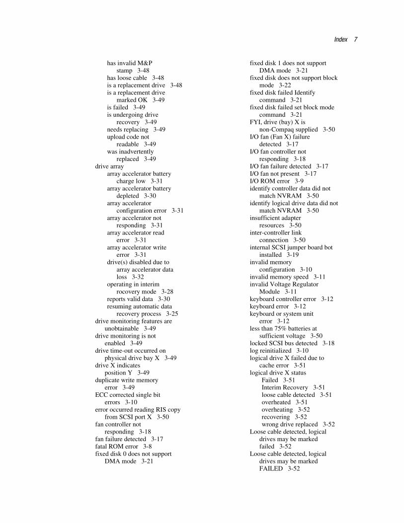
Index 7
has invalid M&Pstamp 3-48
has loose cable 3-48is a replacement drive 3-48is a replacement drive
marked OK 3-49is failed 3-49is undergoing drive
recovery 3-49needs replacing 3-49upload code not
readable 3-49was inadvertently
replaced 3-49drive array
array accelerator batterycharge low 3-31
array accelerator batterydepleted 3-30
array acceleratorconfiguration error 3-31
array accelerator notresponding 3-31
array accelerator readerror 3-31
array accelerator writeerror 3-31
drive(s) disabled due toarray accelerator dataloss 3-32
operating in interimrocovery mode 3-28
reports valid data 3-30resuming automatic data
recovery process 3-25drive monitoring features are
unobtainable 3-49drive monitoring is not
enabled 3-49drive time-out occurred on
physical drive bay X 3-49drive X indicates
position Y 3-49duplicate write memory
error 3-49ECC corrected single bit
errors 3-10error occurred reading RIS copy
from SCSI port X 3-50fan controller not
responding 3-18fan failure detected 3-17fatal ROM error 3-8fixed disk 0 does not support
DMA mode 3-21
fixed disk 1 does not supportDMA mode 3-21
fixed disk does not support blockmode 3-22
fixed disk failed Identifycommand 3-21
fixed disk failed set block modecommand 3-21
FYI, drive (bay) X isnon-Compaq supplied 3-50
I/O fan (Fan X) failuredetected 3-17
I/O fan controller notresponding 3-18
I/O fan failure detected 3-17I/O fan not present 3-17I/O ROM error 3-9identify controller data did not
match NVRAM 3-50identify logical drive data did not
match NVRAM 3-50insufficient adapter
resources 3-50inter-controller link
connection 3-50internal SCSI jumper board bot
installed 3-19invalid memory
configuration 3-10invalid memory speed 3-11invalid Voltage Regulator
Module 3-11keyboard controller error 3-12keyboard error 3-12keyboard or system unit
error 3-12less than 75% batteries at
sufficient voltage 3-50locked SCSI bus detected 3-18log reinitialized 3-10logical drive X failed due to
cache error 3-51logical drive X status
Failed 3-51Interim Recovery 3-51loose cable detected 3-51overheated 3-51overheating 3-52recovering 3-52wrong drive replaced 3-52
Loose cable detected, logicaldrives may be markedfailed 3-52
Loose cable detected, logicaldrives may be markedFAILED 3-52
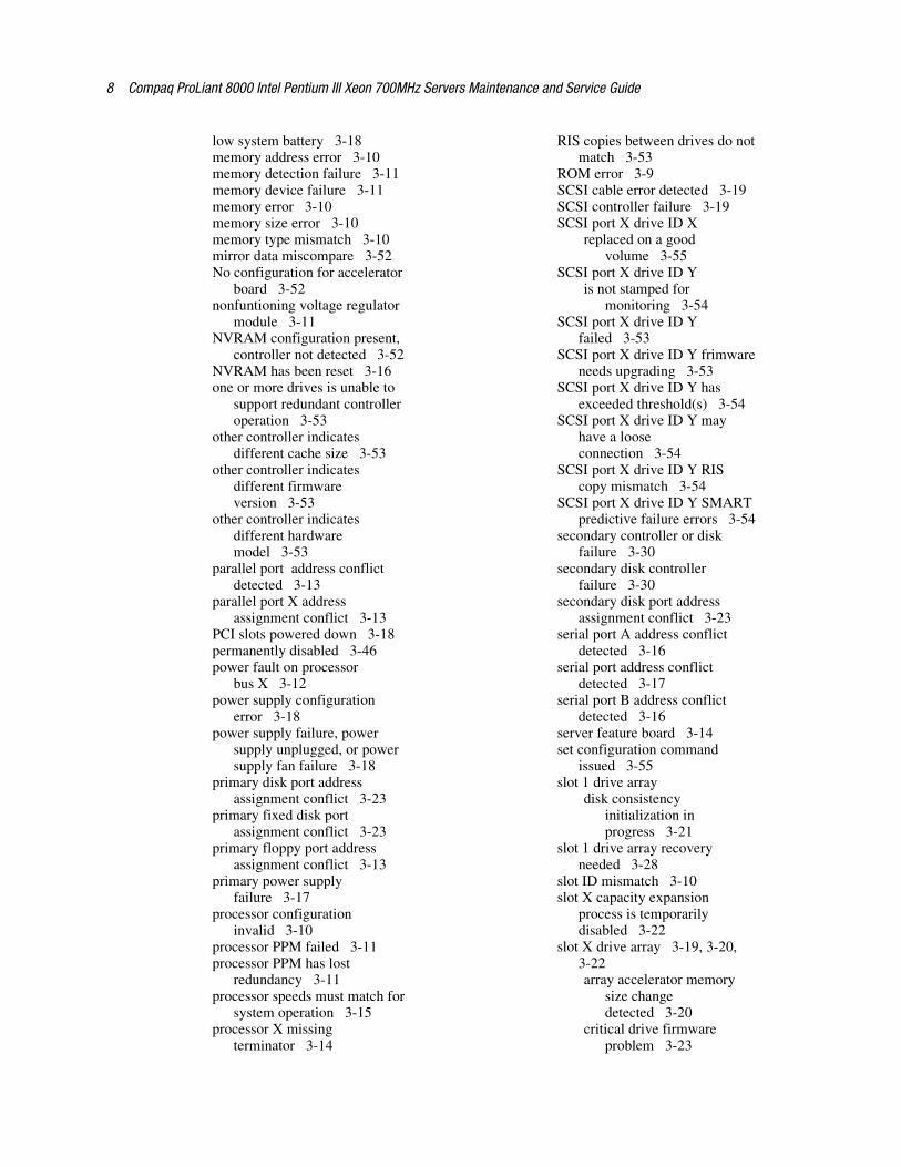
8 Compaq ProLiant 8000 Intel Pentium III Xeon 700MHz Servers Maintenance and Service Guide
low system battery 3-18memory address error 3-10memory detection failure 3-11memory device failure 3-11memory error 3-10memory size error 3-10memory type mismatch 3-10mirror data miscompare 3-52No configuration for accelerator
board 3-52nonfuntioning voltage regulator
module 3-11NVRAM configuration present,
controller not detected 3-52NVRAM has been reset 3-16one or more drives is unable to
support redundant controlleroperation 3-53
other controller indicatesdifferent cache size 3-53
other controller indicatesdifferent firmwareversion 3-53
other controller indicatesdifferent hardwaremodel 3-53
parallel port address conflictdetected 3-13
parallel port X addressassignment conflict 3-13
PCI slots powered down 3-18permanently disabled 3-46power fault on processor
bus X 3-12power supply configuration
error 3-18power supply failure, power
supply unplugged, or powersupply fan failure 3-18
primary disk port addressassignment conflict 3-23
primary fixed disk portassignment conflict 3-23
primary floppy port addressassignment conflict 3-13
primary power supplyfailure 3-17
processor configurationinvalid 3-10
processor PPM failed 3-11processor PPM has lost
redundancy 3-11processor speeds must match for
system operation 3-15processor X missing
terminator 3-14
RIS copies between drives do notmatch 3-53
ROM error 3-9SCSI cable error detected 3-19SCSI controller failure 3-19SCSI port X drive ID X
replaced on a goodvolume 3-55
SCSI port X drive ID Yis not stamped for
monitoring 3-54SCSI port X drive ID Y
failed 3-53SCSI port X drive ID Y frimware
needs upgrading 3-53SCSI port X drive ID Y has
exceeded threshold(s) 3-54SCSI port X drive ID Y may
have a looseconnection 3-54
SCSI port X drive ID Y RIScopy mismatch 3-54
SCSI port X drive ID Y SMARTpredictive failure errors 3-54
secondary controller or diskfailure 3-30
secondary disk controllerfailure 3-30
secondary disk port addressassignment conflict 3-23
serial port A address conflictdetected 3-16
serial port address conflictdetected 3-17
serial port B address conflictdetected 3-16
server feature board 3-14set configuration command
issued 3-55slot 1 drive array
disk consistencyinitialization inprogress 3-21
slot 1 drive array recoveryneeded 3-28
slot ID mismatch 3-10slot X capacity expansion
process is temporarilydisabled 3-22
slot X drive array 3-19, 3-20,3-22array accelerator memory
size changedetected 3-20
critical drive firmwareproblem 3-23
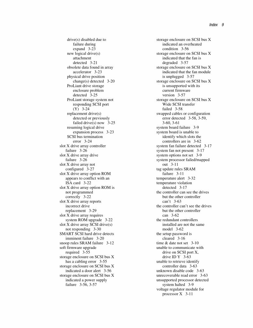
Index 9
drive(s) disabled due tofailure duringexpand 3-23
new logical drive(s)attachmentdetected 3-21
obsolete data found in arrayaccelerator 3-23
physical drive positionchange(s) detected 3-20
ProLiant drive storageenclosure problemdetected 3-25
ProLiant storage system notresponding SCSI port(Y) 3-24
replacement drive(s)detected or previouslyfailed drive(s) now 3-25
resuming logical driveexpansion process 3-23
SCSI bus terminationerror 3-24
slot X drive array controllerfailure 3-26
slot X drive array drivefailure 3-26
slot X drive array notconfigured 3-27
slot X drive array option ROMappears to conflict with anISA card 3-22
slot X drive array option ROM isnot programmedcorrectly 3-22
slot X drive array reportsincorrect drivereplacement 3-29
slot X drive array requiressystem ROM upgrade 3-22
slot X drive array SCSI drive(s)not responding 3-30
SMART SCSI hard drive detectsimminent failure 3-20
snoop rules SRAM failure 3-12soft firmware upgrade
required 3-55storage enclosure on SCSI bus X
has a cabling error 3-55storage enclosure on SCSI bus X
indicated a door alert 3-56storage enclosure on SCSI bus X
indicated a power supplyfailure 3-56, 3-57
storage enclosure on SCSI bus Xindicated an overheatedcondition 3-56
storage enclosure on SCSI bus Xindicated that the fan isdegraded 3-57
storage enclosure on SCSI bus Xindicated that the fan moduleis unplugged 3-57
storage enclosure on SCSI bus Xis unsupported with itscurrent firmwareversion 3-57
storage enclosure on SCSI bus XWide SCSI transferfailed 3-58
swapped cables or configurationerror detected 3-58, 3-59,3-60, 3-61
system board failure 3-9system board is unable to
identify which slots thecontrollers are in 3-62
system fan failure detected 3-17system fan not present 3-17system options not set 3-9system processor failed/mapped
out 3-11tag update rules SRAM
failure 3-11temperature alert 3-32temperature violation
detected 3-17the controller can see the drives
but the other controllercan’t 3-63
the controller can’t see the drivesbut the other controllercan 3-62
the redundant controllersinstalled are not the samemodel 3-62
the setup password iscleared 3-16
time & date not set 3-10unable to communicate with
drive on SCSI port X,drive ID Y 3-63
unable to retrieve identifycontroller data 3-63
unknown disable code 3-63unrecoverable read error 3-63unsupported processor detected
system halted 3-9voltage regulator module for
processor X 3-11
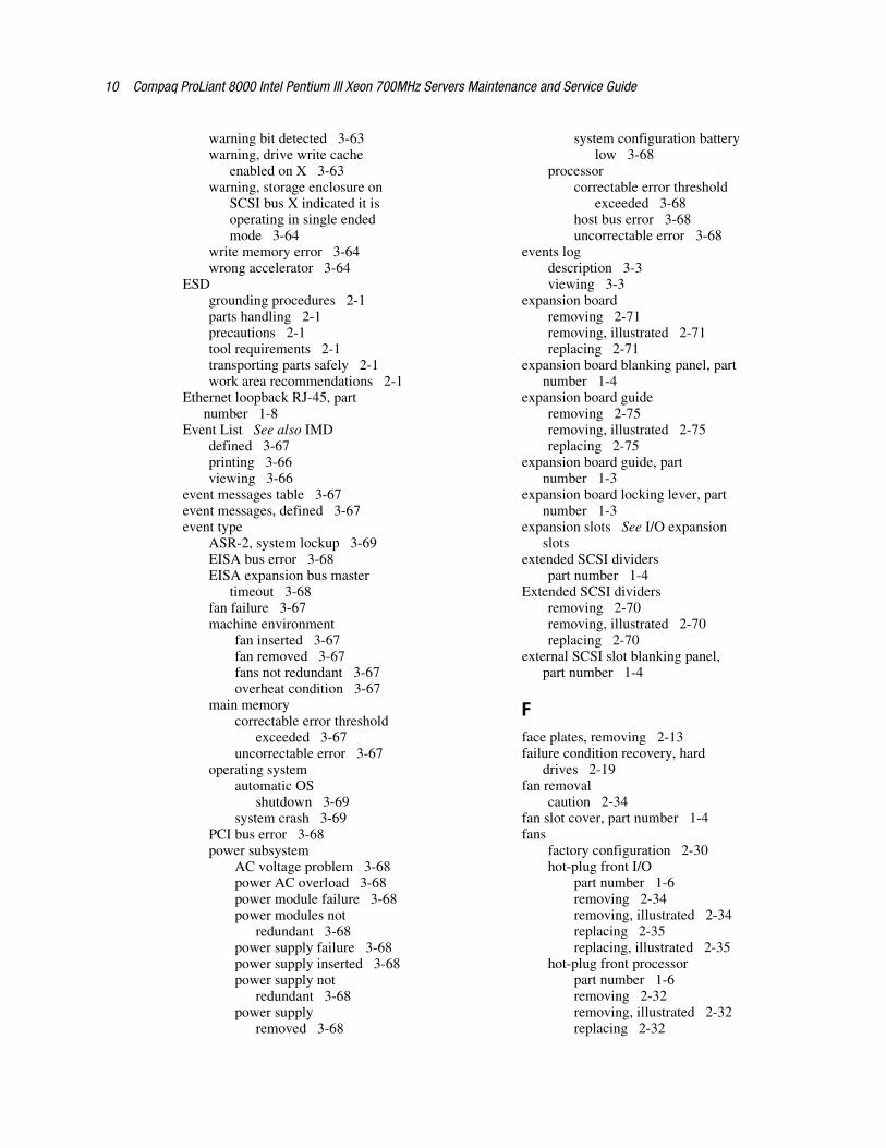
10 Compaq ProLiant 8000 Intel Pentium III Xeon 700MHz Servers Maintenance and Service Guide
warning bit detected 3-63warning, drive write cache
enabled on X 3-63warning, storage enclosure on
SCSI bus X indicated it isoperating in single endedmode 3-64
write memory error 3-64wrong accelerator 3-64
ESDgrounding procedures 2-1parts handling 2-1precautions 2-1tool requirements 2-1transporting parts safely 2-1work area recommendations 2-1
Ethernet loopback RJ-45, partnumber 1-8
Event List See also IMDdefined 3-67printing 3-66viewing 3-66
event messages table 3-67event messages, defined 3-67event type
ASR-2, system lockup 3-69EISA bus error 3-68EISA expansion bus master
timeout 3-68fan failure 3-67machine environment
fan inserted 3-67fan removed 3-67fans not redundant 3-67overheat condition 3-67
main memorycorrectable error threshold
exceeded 3-67uncorrectable error 3-67
operating systemautomatic OS
shutdown 3-69system crash 3-69
PCI bus error 3-68power subsystem
AC voltage problem 3-68power AC overload 3-68power module failure 3-68power modules not
redundant 3-68power supply failure 3-68power supply inserted 3-68power supply not
redundant 3-68power supply
removed 3-68
system configuration batterylow 3-68
processorcorrectable error threshold
exceeded 3-68host bus error 3-68uncorrectable error 3-68
events logdescription 3-3viewing 3-3
expansion boardremoving 2-71removing, illustrated 2-71replacing 2-71
expansion board blanking panel, partnumber 1-4
expansion board guideremoving 2-75removing, illustrated 2-75replacing 2-75
expansion board guide, partnumber 1-3
expansion board locking lever, partnumber 1-3
expansion slots See I/O expansionslots
extended SCSI dividerspart number 1-4
Extended SCSI dividersremoving 2-70removing, illustrated 2-70replacing 2-70
external SCSI slot blanking panel,part number 1-4
Fface plates, removing 2-13failure condition recovery, hard
drives 2-19fan removal
caution 2-34fan slot cover, part number 1-4fans
factory configuration 2-30hot-plug front I/O
part number 1-6removing 2-34removing, illustrated 2-34replacing 2-35replacing, illustrated 2-35
hot-plug front processorpart number 1-6removing 2-32removing, illustrated 2-32replacing 2-32

Index 11
hot-plug rear processorpart number 1-6removing 2-30removing, illustrated 2-30replacing 2-30
locating 2-30POST messages 3-8redundant front processor
part number 1-6removing 2-33removing, illustrated 2-33replacing 2-33
redundant rear processorpart number 1-6removing 2-31removing, illustrated 2-31replacing 2-31
startup sequence 2-30fault tolerance 2-19fire warning 2-2firmware upgrade
caution 3-44flat ribbon cable clips, part
number 1-3flow chart, ASR-2 3-75front air baffle
part number 1-4removing 2-10removing, illustrated 2-10replacing 2-10
front bezelpart number 1-3removing 2-14removing, illustrated 2-14replacing 2-14
front bezel kit, part number 1-3front processor fan
connector, identified 4-4removing 2-32removing, illustrated 2-32replacing 2-32
front processor fan connector,identified 4-4
Ggrounding plug
warning 2-5grounding plug warning 2-5
Hhard drive blanking panel
part number 1-3removing 2-18removing, illustrated 2-18
replacing 2-18hard drive replacement
caution 2-20, 2-21hard drives
18.2-GB Ultra3, partnumber 1-8
4.3-GB Ultra2, part number 1-6,1-8
9.1-GB Ultra2, part number 1-89.1-GB Ultra3, part number 1-8capacity 5-7, 5-8caution 2-20fault tolerance 2-19height 5-7, 5-8hot-plug guidelines 2-19interface 5-7, 5-8mirrored pairs 2-19online spare 2-19operating temperature 5-7, 5-8physical configuration 5-7, 5-8removing 2-20removing, illustrated 2-20replacement ordering rules 2-20replacing 2-20rotational speed 5-7, 5-8seek time 5-7, 5-8size 5-7, 5-8test error codes 3-41transfer rate 5-7, 5-8
Health Driver, description 3-74heavy equipment handling
warning 2-4hot surfaces warning 2-2, 2-5, 2-6,
2-7, 2-8hot-plug basket insulator
part number 1-3removing 2-74removing, illustrated 2-74replacing 2-74
hot-plug devices, removalpreparation 2-4
hot-plug drive cage blanking panelpart number 1-4
hot-plug drive cage, identified 2-15hot-plug front I/O fan
part number 1-6removing 2-34removing, illustrated 2-34replacing 2-35replacing, illustrated 2-35
hot-plug front processor fanpart number 1-6removing 2-32removing, illustrated 2-32replacing 2-32
12 Compaq ProLiant 8000 Intel Pentium III Xeon 700MHz Servers Maintenance and Service Guide
hot-plug hard drive replacementcautions 2-20
hot-plug hard drivesremoving 2-20removing, illustrated 2-20replacing 2-20
hot-plug I/O fan boardremoving 2-36removing, illustrated 2-36replacing 2-36
hot-plug I/O fan board assembly, partnumber 1-6
hot-plug I/O fan LED statusindicators table 4-11
hot-plug I/O fan LEDs,illustrated 4-11
hot-plug power suppliesAC power cord, disconnecting,
illustrated 2-27part number 1-6removing 2-27removing, illustrated 2-28replacing 2-28
hot-plug rear processor fanpart number 1-6removing 2-30removing, illustrated 2-30replacing 2-30
Hot-Plug Wide Ultra2 SCSI harddrivestable 5-7
Hot-Plug Wide Ultra3 SCSI harddrivestable 5-8
hot-pluggable parts, preparationprocedures 2-3
II/O board
connectors, illustrated 4-3locating 4-7removing 2-77removing, illustrated 2-77, 2-78replacing 2-78
I/O board connectorstable 4-3
I/O expansion boardremoving 2-71removing, illustrated 2-71replacing 2-71
I/O expansion board slotsaccessing 2-66illustrated 2-65, 2-66table 2-65, 2-66
I/O expansion slotsaccessing 2-63identifying 2-63
I/O fan boardremoving 2-36removing, illustrated 2-36replacing 2-36
I/O system board, part number 1-6IDE max slimline CD-ROM drive
specificationstable 5-5
IMDdescription 3-65Event List, defined 3-67panel with cable, part
number 1-6removing 2-62removing, illustrated 2-62replacing 2-62
IML See also Critical Error Logaccessing from Compaq Insight
Manager 3-65defined 3-65, 3-80description 3-3error types, explained 3-80security levels defined 3-65viewing 3-65, 3-66, 3-80
initialization failure 3-8Insight Agents, defined 3-88Insight Desktop Agents,
defined 3-88Insight Management Agents,
enabling 3-70Inspect Computer utility,
accessing 3-33Inspect listing, printing 3-4Inspect utility
accessing 3-2booting remotely 3-78description 3-2, 3-4printing Inspect listing 3-4running 3-4
Integrated ManagementDisplay See IMD
Integrated ManagementLog See IML
Integrated Remote Consolefeatures 3-74
integrated server management,features 3-70
interface boardremoving 2-76removing, illustrated 2-76replacing 2-76
interlock/air sensor connector,identified 4-4
Index 13
internal rear processor fanconnector, identified 4-4
internal/external battery switchsettings tables 4-6
invalid electronic serial number 3-9IP access 3-76IP/IPX, using network features 3-72IRQ conflict, resolving 3-3
Jjumper settings, obtaining 3-3
Kkeyboard
connector, identified 4-4part number 1-8test error codes 3-37
LLED holder clip, part number 1-3LED status indicators
CD-ROM drive, illustrated 4-15hot-plug hard drive,
illustrated 4-13hot-plug I/O fan,
illustrated 4-11PCI Hot Plug
illustrated 4-12viewing 4-12
powerremoving 2-22removing, illustrated 2-23replacing 2-23
power supply, illustrated 4-14system interlock, locating 2-3
left side access panelpart number 1-3removing 2-8removing, illustrated 2-8replacing 2-8
lithium battery caution 2-79lock bar
removing 2-24removing, illustrated 2-24replacing 2-24
lower processor support structurepart number 1-3removing 2-55removing, illustrated 2-56replacing 2-56
Mmain processor air baffle
removing 2-12removing, illustrated 2-12replacing 2-12
maintenance and service guide, partnumber 1-7
mass media and removable mediaarea configurationstable 2-15
mass storageconfigurations 2-15location 2-15location, illustrated 2-15
mechanical parts, exploded view 1-2illustrated 1-2
mechanical spare parts list 1-3memory
bank locations 2-38description 2-37DIMM socket locations 2-38installation guidelines 2-37maximum supported 2-37part number 1-6, 1-8POST messages 3-8removing DIMM 2-41removing DIMM,
illustrated 2-41replacing DIMM 2-41socket and bank locations,
illustrated 2-38specifications 5-4test error codes 3-35upgrade combinations,
table 2-37memory bank locations,
illustrated 2-38memory board retention bracket, part
number 1-4memory board, part number 1-6memory errors, recorded to log 3-80memory expansion board
connector, identified 4-4DIMM locations 2-38removing 2-39removing, illustrated 2-40replacing 2-40
memory expansion board bracket,removing, illustrated 2-39
memory installationcaution 2-41
14 Compaq ProLiant 8000 Intel Pentium III Xeon 700MHz Servers Maintenance and Service Guide
memory socket locations,illustrated 2-38
memory test error codestable 3-35
modemtest error codes 3-40
modem communications test errorcodestable 3-40
mouse connector, identified 4-4multiple-rack installations
warning 2-5
NNC3131 10/100 TX UTP Network
Interface Controller, partnumber 1-6
NC3131 Fast Ethernet 64 PCI Dual10/100 NICspecifications 5-10
NC3131 Fast Ethernet 64 PCI Dual10/100 NIC, identified 4-2
Netelligent Management,defined 3-87
networkaccess, configuring ASR-2
for 3-76card slot, selecting 3-78frame type, selecting 3-78host name, setting 3-78interface fault recovery,
defined 3-83network interface connection
warning 2-2Network Interface Controller See
NICnetwork IP
address, setting 3-78net mask, setting 3-78router address,
setting 3-78network protocol, setting 3-77NIC, test error codes 3-41ninth VRM See Processor board
Processor Power Moduleno SCSI devices detected 3-9non-hot-plug devices, removal
preparation 2-4non-hot-pluggable parts, preparation
procedures 2-3non-system disk or disk error 3-9NVRAM, clearing 3-85
Ooperating server without access
panels caution 2-6, 2-7, 2-8operating server without cover
caution 2-5operating system
booting into 3-78driver support 5-10restart SCU setting for ASR-2
table 3-79overheating
caution 2-5, 2-6, 2-7, 2-8, 2-15,2-21, 2-25, 2-28
Ppacking materials, part number 1-7pager
booting Compaq Utilitiesfrom 3-76
serial interface, selecting 3-77setting dial string 3-76setting message 3-76settings 3-76testing 3-77
parallel port connector,identified 4-4
parallel printer test error codestable 3-37
parity check 2 3-9part numbers
baffle kit 1-4battery 1-6blanking panel 1-4buns 1-7cable grommet 1-3cache accelerator 1-8carton 1-7casters 1-4CD-ROM drive 1-6chassis 1-3country kit 1-7drive cage blanking panel 1-4drive cage with backplane
board 1-3EMI shield 1-4Ethernet loopback RJ-45 1-8expansion board blanking
panel 1-4expansion board guide 1-3expansion board locking
lever 1-3extended SCSI dividers 1-4external SCSI slot blanking
panel 1-4
Index 15
fan slot cover 1-4fans
hot-plug front I/O 1-6hot-plug front
processor 1-6hot-plug rear processor 1-6redundant front
processor 1-6redundant rear
processor 1-6flat ribbon cable clips 1-3front air baffle 1-4front bezel 1-3front bezel kit 1-3hard drive blanking panel 1-3hard drives
18.2-GB Ultra3 1-84.3-GB Ultra2 1-6, 1-89.1-GB Ultra2 1-89.1-GB Ultra3 1-8
hot-plug basket insulator 1-3hot-plug drive cage blanking
panel 1-4hot-plug I/O fan board
assembly 1-6hot-plug power supply 1-6I/O system board 1-6illustrated parts map 1-8IMD panel with cable 1-6keyboard 1-8LED holder clip 1-3left side access panel 1-3lower processor support
structure 1-3maintenance and service
guide 1-7memory 1-6, 1-8memory board 1-6memory board retention
bracket 1-4miscellaneous hardware kit 1-4miscellaneous plastics kit 1-3miscellaneous power cable
kit 1-7miscellaneous screw kit 1-7miscellaneous signal cable
kit 1-7NC3131 10/100 TX UTP
Network InterfaceController 1-6
PCI Hot Plug switch board 1-6power backplane board 1-6Power On/Standby switch 1-6power supply lock bar with lock
kit 1-4processor 1-6
processor and VRM airbaffle 1-4
processor board 1-6processor board support 1-4processor board support
retainer 1-4processor cage support
brace 1-4processor guides 1-3Processor Power Module 1-6processor support structures 1-3processor terminator board 1-6processors 1-8rack mout kit 1-7rear air baffle 1-4redundant fan slot cover 1-4removable media blanking
panel 1-3removable media blanking panel
EMI shield 1-4removable media trim 1-3return kit 1-7right side access panel 1-3SCSI dividers 1-4slide fillers 1-3Smart Array controller 1-6system board 1-6top access panel 1-3tower conversion kit 1-7upper processor support
structure 1-3parts
catalog, illustrated 1-1handling 2-1preventing ESD damage 2-1storing 2-1transporting 2-1
passwords, disabling 3-85PCI boards, configuring
automatically 3-3PCI Hot Plug access doors
opening, illustrated 2-64unlocking, illustrated 2-63
PCI Hot Plug interface boardremoving 2-76removing, illustrated 2-76replacing 2-76
PCI Hot Plug LEDstable 4-12
PCI Hot-Plug switch boardpart number 1-6
personal injurywarning 2-2, 2-4
personal injury warning 2-2, 2-3,2-5, 2-6, 2-7, 2-8, 2-63
plastics kit, contents 1-3
16 Compaq ProLiant 8000 Intel Pentium III Xeon 700MHz Servers Maintenance and Service Guide
pointing device interface, test errorcodes 3-43
pointing device test error codestable 3-43
POSTbeeps, description 3-8defined 3-7error messages 3-7, 3-8
POST Error Messagestable 3-8
POST messages1700 series 3-29beeps only 3-8fans 3-8memory 3-8non-numeric series 3-8, 3-9parity errors 3-9resume 3-9Run System Configuration
Utility 3-9power backplane board
part number 1-6removing 2-29removing, illustrated 2-29replacing 2-29
power cable kit, part number 1-7power fluctuations
caution 2-5power fluctuations, protecting
against 2-5Power On/Standby switch
disconnecting from the I/Oboard, illustrated 2-22
part number 1-6plastic switch cover,
removing 2-23removing 2-22removing, illustrated 2-23replacing 2-23
power suppliesAC power cord, disconnecting,
illustrated 2-27hot-plug, removing 2-27hot-plug, replacing 2-28loading requirements 2-25location 2-25part number 1-6positioning, illustrated 2-25power input requirements 5-2providing redundancy 2-25removing, illustrated 2-28specifications 5-3
power supply blanking panelremoving 2-26removing, illustrated 2-26replacing 2-26
power supply connectors,identified 4-2
power supply indicatorstable 4-14
power supply installationwarning 2-5
power supply lock barpart number 1-4removing 2-24removing, illustrated 2-24replacing 2-24
power supply replacementcaution 2-25, 2-27, 2-28
power supply requirementstable 2-25
power supply specificationstable 5-3
Power-On Self-Test See POSTPPM See Processor Power Modulepredictive failure alert
guidelines for drivereplacement 2-19
primary processor test error codestable 3-34
processor and VRM air baffle, partnumber 1-4
processor boardconnectors, identified 4-2connectors, illustrated 4-4part number 1-6removing 2-58removing, illustrated 2-61replacing 2-61switch bank, illustrated 4-5
processor board bus/core frequencyratio switch settings tables 4-5
processor board connectorstable 4-4
processor board interlock LED statustable 4-10
Processor board Processor PowerModule 2-50, 2-59, 2-60
processor board slot locationstable 2-45
processor board support retainer, partnumber 1-4
processor board support, partnumber 1-4
processor cage support bracepart number 1-4
processor fanremoving 2-30, 2-31, 2-32, 2-33removing, illustrated 2-30, 2-31,
2-32, 2-33replacing 2-30, 2-31, 2-32, 2-33
processor guides, part number 1-3

Index 17
processor installationcaution 2-49
processor mixing by cache sizetable 2-48
Processor Power Moduleinstallation caution 2-53LED status 4-7part number 1-6removing 2-50, 2-51removing, illustrated 2-50, 2-52,
2-53replacing 2-50, 2-53slots, identified 2-45
processor slots, identified 2-45processor speeds, selecting
caution 2-48processor support brace
removing, illustrated 2-43, 2-59processor support structure
part number 1-3removing 2-55, 2-57removing, illustrated 2-56, 2-57replacing 2-56, 2-57
processor terminator boardpart number 1-6removing 2-54removing, illustrated 2-54replacing 2-54slots, identified 2-45
processor terminator board slots,identified 2-45
processorsinstallation guidelines 2-47installation order 2-47installing 2-49installing, illustrated 2-49part number 1-6, 1-8removing 2-46removing, illustrated 2-47slots, identified 2-45speed, detecting 2-48test error codes 3-34unlocking, illustrated 2-46
Rrack mount kit, part number 1-7rack stability warning 2-4, 2-5rack warnings 2-5Rapid Recovery Engine,
enabling 3-70rapid recovery services 3-70rear air baffle
part number 1-4removing 2-11removing, illustrated 2-11
replacing 2-11rear panel
connectors 4-1connectors, illustrated 4-2
rear processor fanredundant
removing 2-31removing, illustrated 2-31replacing 2-31
removing 2-30removing, illustrated 2-30replacing 2-30
rear processor fan connector,identified 4-4
rear view of the I/O expansion boardslots, illustrated 2-66
recoveryattended 3-71automatic 3-70, 3-71environmental 3-71from software error 3-71rapid recovery services 3-70unattended 3-71
redundant fan slot cover, partnumber 1-4
redundant front processor fanpart number 1-6removing 2-33removing, illustrated 2-33replacing 2-33
redundant rear processor fanconnector, identified 4-4part number 1-6removing 2-31removing, illustrated 2-31replacing 2-31
redundant ROM imagerecovery 3-86
releasing an array controller,illustrated 2-67
remote management features,defined 3-84
Remote Management, defined 3-87remote service features,
defined 3-84Remote Utilities, accessing 3-33removable media bay,
identified 2-15removable media blanking panel
part number 1-3removing 2-16removing, illustrated 2-16replacing 2-16
removable media blanking panel EMIshield, part number 1-4
18 Compaq ProLiant 8000 Intel Pentium III Xeon 700MHz Servers Maintenance and Service Guide
removable media devicesconfigurations 2-15location 2-15location, illustrated 2-15removing 2-17removing, illustrated 2-17replacing 2-17
removable media power connector,identified 4-4
removable media trimpart number 1-3removing 2-13removing, illustrated 2-13replacing 2-13
removal and replacementprocedures 2-1
removing all power from systemwarning 2-2
removing server from rack 2-4resource conflict, resolving 3-3resource, Smart Array controller user
guide 3-25Resume POST message 3-9return kit, part number 1-7revision history table
accessing 3-82defined 3-82table 3-82where stored 3-82
right side access panelpart number 1-3removing 2-7removing, illustrated 2-7replacing 2-7
ROM is corrupted 3-85ROMPaq
disaster recovery 3-85error recovery options 3-84Firmware Upgrade Utility,
accessing 3-5interruption 3-85
Run System Configuration UtilityF10 key POST message 3-9
Sscrews, part number 1-7SCSI CD-ROM drives See
CD-ROM drivesSCSI devices
POST messages 3-9SCSI dividers
part number 1-4removing 2-70removing, illustrated 2-70replacing 2-70
SCSI hard drive test error codestable 3-41
SCSI hard drives See also harddrivesremoving 2-20removing, illustrated 2-20replacing 2-20
SCSI tape drive test error codestable 3-42
SCSI tape drives See tape drivesSCSI, identified 4-2SCSI/IDE CD-ROM test error codes
table 3-42SDRAM DIMM See memorysecurity levels
Caution, defined 3-65Critical, defined 3-65Repaired, defined 3-65Status, defined 3-65
security, ASR-2 3-79serial port
connectors, identified 4-4test error codes 3-40
serial test error codestable 3-40
serverprotecting from power
fluctuations 2-5removing from rack 2-4specifications 5-2warnings and precautions 2-5weight 5-2
Server Health Logs 3-80setting bus/core ratio switches
caution 2-48shipping materials, part number 1-7signal cable kit, part number 1-7single-rack installations
warning 2-5slide fillers, part number 1-3slot X drive array
replacement drive(s) detected ORpreviously failed drive(s)now operational 3-25
Smart Array controllercache specification 5-9data transfer method 5-9dimensions 5-9heat dissipated 5-9hot-plug guidelines 2-19logical drives supported 5-9maximum drives supported 5-9part number 1-6protocol 5-9SCSI port connectors 5-9specifications 5-9

Index 19
temperature range 5-9total transfer rate 5-9user guide 3-25
SmartStart and Support Software CDbooting from 3-4contents 2-1, 3-5running utilities 3-5
software errorrecovery boot option 3-73recovery from 3-71, 3-73recovery timeout 3-73
specificationsCD-ROM drive 5-5diskette drive 5-4memory 5-4NIC 5-10power supply 5-3Smart Array controller 5-9
Standby mode, description 2-4standby recovery
server option 3-73server port 3-73time-out 3-73
static electricity See ESDstorage automatic reconstruction,
defined 3-83storage fault recovery tracking,
defined 3-83Survey Utility, viewing 3-66switch settings, obtaining 3-3switches
battery, illustrated 4-6bus/core frequency ratio,
setting 4-5CD-ROM ejector,
identified 4-15diskette ejector, identified 4-15Power On/Standby
description 2-4disconnecting from the I/O
board, illustrated 2-22part number 1-6plastic switch cover,
removing 2-23removing 2-22removing, illustrated 2-23replacing 2-23
symbolsused in equipment 2-2
symbols on equipmentCaution 2-2Warning 2-2
system board, part number 1-6system components
exploded view 1-5spare parts list table 1-6
System Configuration CD, bootingfrom 3-4
System Configuration Utilityaccessing 3-5booting remotely 3-78description 3-3executing 3-6messages 3-4running 3-3selecting Diagnostics from 3-33software location 2-1
system configuration,determining 3-4
system interlock LED statusindicatorsdefined 4-7front panel, function 4-7front panel, illustrated 4-7I/O board table 4-9I/O board, function 4-8I/O board, illustrated 4-8processor board 4-10processor board, illustrated 4-10
system interlocksdescription 2-3, 4-7locating 2-3
system partition, accessing utilitiesfrom 3-5
system unit specificationstable 5-2
system unit specifications 5-2
Ttape drives, test error codes 3-42technician notes 2-2Test Computer utility,
accessing 3-33test error codes
CD-ROM drive 3-42diskette drive 3-39hard drive 3-41keyboard 3-37memory 3-35modem 3-40NIC board 3-41parallel printer 3-37pointing device interface 3-43processor 3-34SCSI hard drive 3-41SCSI tape drive 3-42SCSI/IDE CD-ROM drive 3-42serial port 3-40tape drive 3-42video display unit 3-38
thermal shutdown 3-73
20 Compaq ProLiant 8000 Intel Pentium III Xeon 700MHz Servers Maintenance and Service Guide
toolsrequired for service
procedures 2-1using non-conductive 2-1
top access panelpart number 1-3removing 2-6removing, illustrated 2-6replacing 2-6
tower conversion kit, partnumber 1-7
troubleshootinghard drive replacement
conditions 4-13hard drives 2-19system does not power up 4-9system interlock LED is
amber 4-7system interlock LEDs 4-10system interlock status
LEDs 4-9turning off the server 2-4
Uuninterruptible power supply See
UPSunoccupied processor slots
caution 2-45Upgrade Firmware utility,
accessing 3-33upper processor support structure
part number 1-3removing 2-57removing, illustrated 2-57replacing 2-57
UPSshutdown threshold 3-73using 2-5
utilitiesaccessing 3-5ADU
accessing 3-5description 3-3executing 3-6
allowing network access to 3-77Array Configuration
accessing 3-5, 3-6executing 3-6
Compaqconfiguring server to
start 3-73running on IPX
network 3-72running remotely 3-72
Survey Utility,description 3-2
Survey, installing 3-2System Reference
Library 3-70Compaq Insight Manager 3-87creating diskette versions 3-6DAAD
accessing remotely 3-84description 3-3software location 2-1
Diagnose Drive Array,accessing 3-33
Diagnosticsaccessing 3-5accessing from system
partition 3-5menu choices 3-33selecting from System
ConfigurationUtility 3-33
sofware location 2-1Firmware Upgrade,
accessing 3-5Health Driver 3-74IML Management Utility,
defined 3-66Inspect
accessing 3-2description 3-2, 3-4printing Inspect listing 3-4running 3-4
Inspect Computer,accessing 3-33
Integrated Management Log,description 3-3
Remote Utilities, accessing 3-33ROMPaq Firmware Upgrade,
accessing 3-5running from SmartStart and
Support Software CD 3-6starting from ASR-2 3-76Survey, defined 3-66System Configuration
accessing 3-5booting from pager 3-76description 3-3executing 3-6running 3-3software location 2-1
Test Computer, accessing 3-33Upgrade Firmware,
accessing 3-33
Index 21
Vvideo display unit test error codes
table 3-38video display unit, test error
codes 3-38video, disabling on-board 3-85VRM See Processor Power Module
Wwarnings
technician notes 2-2work area recommendations 2-1Workstation Management,
defined 3-87