Embed Size (px)
DESCRIPTION
Project Planning Document (Version 2.1)
Citation preview
The Structural Performance of Cable Supported-Structures During Fire
MEng Thesis Project
Project Planning Document
Version 2.1
Prepared by : Hector Haines and Jonathan Noblett
31st October 2011
Hector Haines (s0791309)Jonathan Noblett (s0791627)
School of EngineeringThe University of Edinburgh
Faraday BuildingThe King's Buildings
Mayfield RoadEdinburgh
EH9 3JL
Project Planning Document for Civil & Environmental Engineering Thesis Projects – Version 2, October 2011
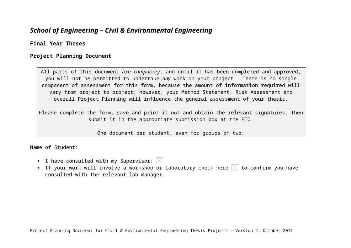
School of Engineering – Civil & Environmental Engineering
Final Year Theses
Project Planning Document
All parts of this document are compulsory, and until it has been completed and approved, you will not be permitted to undertake any work on your project. There is no single component of assessment for this form, because the amount of information required will vary from project to project; however, your Method Statement, Risk Assessment and overall Project Planning will influence the
general assessment of your thesis.
Please complete the form, save and print it out and obtain the relevant signatures. Then submit it in the appropriate submission box at the ETO.
One document per student, even for groups of two.
Name of Student:
I have consulted with my Supervisor: If your work will involve a workshop or laboratory check here to confirm you have consulted with the relevant lab manager.
Project Planning Document for Civil & Environmental Engineering Thesis Projects – Version 2, October 2011

IntroductionProvide a brief overview of your project, indicating the problem you are investigating and the main aims and objectives. It is accepted of course that plans change which is why you will review this document in your interim submission due in January.
Fire poses a potentially serious threat to a range of cable-supported structures. If a laden oil tanker ship collides with the pier of a suspension bridge and the contents catch fire, could the bridge collapse or sustain serious damage? What are the consequences of a fire inside an airport terminal building where a long-span roof is supported by exposed ties? The interplay of the fire scenario, material performance at elevated temperatures, geometric changes due to thermal expansion, and load path redistribution is complex. The use of resin filled sockets in high tensile structures such as suspension bridges is becoming relatively well established, despite the fact that there is little understanding into how these assemblies perform in a fire.
Aim: To investigate and quantify the performance of high tensile steel rope in resin filled sockets in fire.
Objectives: Produce resin sockets in accordance to the design specification in BSI 463-1:1970 and BSI 7035:1989
Test resin socket systems and wire to failure in axial tension to determine breaking load
Test resin socket systems until failure, in a controlled thermal environment while subject to pre-loaded axial tension (variable between tests)
Create a computer model that can give concordant behaviour with experimental observations
Test the residual axial strength of unfailed socket systems
Depending on time constraints, repeat tests while varying the temperature-time curve
Create a document that analyses our data, then comprehensivly concludes on our findings. Write a discussion on the current performance of contemporary systems and comment on any potential improvements that could be made to the system
Project Planning Document for Civil & Environmental Engineering Thesis Projects – Version 2, October 2011

Method StatementThe Method Statement is an overview of how you expect to conduct your project. It serves multiple purposes:
Helps you think through all the steps required to complete your project. Acts as a discussion document with your supervisor and technical staff. The Method Statement is used to identify items that need to be included in your Risk Assessment, Resource Planning, and Schedule of
Work (below). The Method Statement is the first thing to be written, because it identifies the items that need to be considered below.
Provide an overview of how you expect to conduct your project. Consider, amongst other items, the stages of your project, potential hazards of the work involved and the resources that will be needed.
The project mainly involves the experimental testing of the steel wire and anchorage assemblies in a hydraulic tensile testing machine with a thermal oven.
Prior to testing
Compile the Project Planning Document and conduct a Literature review Source the materials for testing, and gain specifications on size and strength from the manufacturer Prepare the materials for testing (assemble if necessary – see document on Rope Cable Terminations)
During Testing (see specific method statements for up to date procedures)
3 by Axial Strength Test of wires to determine failure load (stated as 111kN for 12mm wire but it is thought to have strength ~550kN). Varying Stress/Strain with Time.
4 by Resin Socket Test at each of the following strengths related to ultimate strength found in previous test; 10%, 20%, 30%, 50% and 90% (i.e. 20 tests in all). Load constant in each test, vary Temperature with Time. Measure Strains/Failure and Temperature of Resin with thermocouple.
Note: Thermal Load (curve) needs to be defined. Ideally try to simulate a real fire situation, therefore use rapid heating of sample – 10°/min. Further test options involve the modifying of the heating curve – not included here, possibly outside realistically attainable scope.
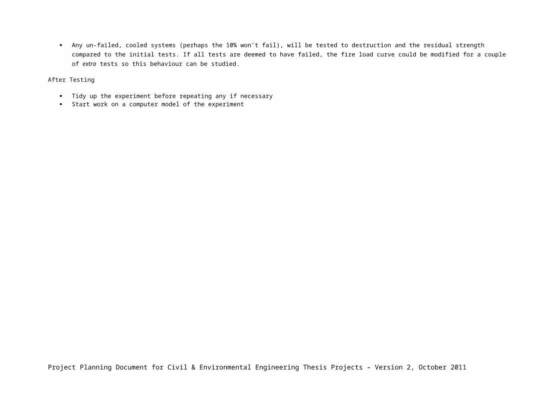
Any un-failed, cooled systems (perhaps the 10% won’t fail), will be tested to destruction and the residual strength compared to the initial tests. If all tests are deemed to have failed, the fire load curve could be modified for a couple of extra tests so this behaviour can be studied.
After Testing
Tidy up the experiment before repeating any if necessary Start work on a computer model of the experiment
Project Planning Document for Civil & Environmental Engineering Thesis Projects – Version 2, October 2011

Risk AssessmentOn the next page is a blank Risk Assessment form that you will complete for your project. Below is a sample Risk Assessment. Hazards should have been identified as part of your Method Statement thought process
Risk Assessment for your projectDescription of Hazard, including potential harm
Probability(1=very unlikely; 10=very likely)
Severity(1=minor; 10=very severe)
Initial Risk(Probability x Severity)
Mitigation Measures(Full description including resources needed)
Residual Risk(Remaining risk after mitigations in place)
Working with tools and large objects in laboratories – harm from dropped objects, tool injuries etc.
5 4 20Personal Protective equipment – gloves, eye protection and protective boots/shoes to be worn. PPE to be appropriate for task
2x2=4
Slips and trips leading to injury 5 4 20 Care to be taken. Work area to be kept tidy and tools/equipment put away when not needed. Spillages to be cleared up promptly. Hazards such as steps or protruding scaffolds or similar to be highlighted with bright colours and/or fenced off.
2x2=4
Working with epoxy resin – respiratory and skin irritation.
6 3 18 Disposable gloves to be worn. Work in well-ventilated area. Adhere to manufacturer’s safety document.
1x2=2
Lifting socket system into place for testing – back injury, harm from dropped specimen etc.
4 5 20 Two people are required to lift and fix the system in place. Safety boots and riggers gloves to be worn.
2x2=4
Description of Hazard, Probability Severity Initial Risk Mitigation Measures Residual Risk
Project Planning Document for Civil & Environmental Engineering Thesis Projects – Version 2, October 2011
including potential harm (1=very unlikely; 10=very likely)
(1=minor; 10=very severe)
(Probability x Severity)
(Full description including resources needed)
(Remaining risk after mitigations in place)
Burns/scalds from hot oven or socket
5 8 40 Allow significant and ample time for cooling of machine and socket system. Always wear full protective clothing and gloves
3x2=6
Leakage or spills of hot resin from socket system
5 7 35 Monitor specimen visually from a safe distance. Respond to leaks cautiously and as appropriate. Allow ample time for cooling to take place.
3x3=9
Wire rope breaking under large stresses
10 9 90 Stay clear of sample under large stresses. Always wear goggles and protective clothing
10x1=10
Breaking the test machine - loss of time. Expensive to repair or replace.
4 6 24 Load only up to the safe capacity of the machine.
1x1=1
Summary of resources neededThis section must indicate with as much detail as possible the physical as well as human resources that you need for your project, as well as costings. It is essential that this is discussed with your supervisor so that any necessary approvals for materials/equipment and requests for technical help can be made early on in your project.
Research documents Steel Wire Rope, similar if not identical to ropes used in industry Anchorage of Spelter Socket, and others as required, similar if not identical to industry Resin, identical to that used in contemporary socket systems Testing machine large, and strong enough to fit the entire specimen with the socket inside a temperature controlled oven if possible Help from the workshops to machine parts and make fittings for the anchorages and free ends of the assembly Computers with ABAQUS CAE for the finite modelling of the system
Project Planning Document for Civil & Environmental Engineering Thesis Projects – Version 2, October 2011

Schedule of workProvide an overall Gantt chart of your proposed work. This chart can then also be used in your Web Poster. You should create your Gantt chart in Excel, MS Project or other suitable application and paste here.
Signatures:Student:-------------------------------------------------------------------------------------------------- Date--------------------------------------------
Supervisor:----------------------------------------------------------------------------------------------Date--------------------------------------------
Lab/Workshop manager (if applicable)----------------------------------------------------------Date--------------------------------------------
Project Planning Document for Civil & Environmental Engineering Thesis Projects – Version 2, October 2011