Embed Size (px)
Citation preview

Asycube
Programming Guide
Document ASYCUBE_Programming_Guide_EN
000.101.572
Version A1 Date 12.12.2017

Asycube - Asyril SA
Programming Guide © Copyright Asyril S.A.
000.101.572 Version : A1
2/83
Table of Contents
1. INTRODUCTION .................................................................................................................................. 5
1.1. GENERALITIES ...................................................................................................................................... 5
2. GENERAL DESCRIPTION OF THE ASYCUBE ............................................................................. 6
2.1. VIBRATION CONVENTION ...................................................................................................................... 6
2.2. VIBRATION SETS ................................................................................................................................... 8
2.3. SEQUENCES ......................................................................................................................................... 9
2.4. LOAD/SAVE IN MEMORIES ..................................................................................................................... 9
3. HOW TO USE THE ASYCUBE ....................................................................................................... 10
3.1. INTEGRATION MODES ......................................................................................................................... 10
3.1.1. Direct connection to the Asycube, configuration with Asycube HMI ..................................... 11
3.1.2. Direct connection to the Asycube ............................................................................................... 12
3.1.3. Connection to the Asycube with the Plugin .NET and configuration with Asyril HMI.......... 13
3.1.4. Connection to the Asycube with the Plugin .NET and configuration with the customer user
interface using the Plugin .NET ................................................................................................................ 14
3.1.5. Modbus TCP connection with the Asycube, configuration with Asycube HMI ..................... 15
3.2. PRODUCTION CYCLE WITH SEQUENCES............................................................................................. 16
3.3. QUESTIONS AND ANSWERS ................................................................................................................ 17
3.3.1. Which vibration set or sequence is currently selected? .......................................................... 17
3.3.2. How do I know if some parameters of the current vibration set have been modified? ....... 17
3.3.3. What is the duration of a specific sequence? ........................................................................... 17
3.3.4. How do I know when a vibration or a sequence is finished? .................................................. 17
3.3.5. How do I backup all vibration set on the computer? ................................................................ 17
3.3.6. How is the center of mass of the components on the platform transferred to the command
ES ? 18
4. ASYCUBES PARAMETERS............................................................................................................ 19
4.1. CONFIGURATION ................................................................................................................................ 19
4.2. PLATFORM VIBRATIONS ..................................................................................................................... 22
4.2.1. For the Asycube 50 and Asycube 80 ......................................................................................... 22
4.2.2. For the Asycube 240 and Asycube 530..................................................................................... 23
4.3. HOPPER VIBRATIONS OR OUTPUTS ACTIVATIONS ............................................................................ 26
4.3.1. Hopper vibrations (Asycube 50 and Asycube 80) .................................................................... 26
4.3.2. Outputs activations (Asycube 240 and Asycube 530) ............................................................. 27
4.4. SEQUENCES ....................................................................................................................................... 28
5. TCIP/IP COMMUNICATION ............................................................................................................. 32
5.1. CONFIGURATION ................................................................................................................................ 32
5.2. ASYCUBE COMMUNICATION PROTOCOL ............................................................................................. 32

Asycube - Asyril SA
Programming Guide © Copyright Asyril S.A.
000.101.572 Version : A1
3/83
5.3. COMMUNICATION ERROR CODE (SERIAL BIT) .................................................................................... 34
5.4. COMMANDS ........................................................................................................................................ 35
5.4.1. Description and ranges of parameters....................................................................................... 35
5.4.2. Level access .................................................................................................................................. 36
5.4.3. Access Single Parameters .......................................................................................................... 36
5.4.4. Access to parameters................................................................................................................... 37
5.4.4.1. Platform Vibration Parameters .............................................................................................................. 37
5.4.4.2. Hopper Vibration Parameters (Asycube 50 and 80) .......................................................................... 38
5.4.4.3. Outputs Activation Parameters (Asycubes 240 and 530) ................................................................. 38
5.4.4.4. Sequence Parameters ........................................................................................................................... 40
5.4.4.4.1. Load...................................................................................................................................................... 40
5.4.4.4.2. Save ..................................................................................................................................................... 41
5.4.5. Vibration set and sequence selection ........................................................................................ 41
5.4.6. Backlight ......................................................................................................................................... 42
5.4.7. System States ............................................................................................................................... 42
5.4.8. Platform Vibrations (C for Cube) ................................................................................................ 43
5.4.9. Hopper vibration or Outputs activation ...................................................................................... 44
5.4.9.1. Asycubes 50 and 80: Hopper Vibrations (B for Bulk) ........................................................................ 44
5.4.9.2. Asycubes 240 and 530: Outputs activation ......................................................................................... 45
5.4.10. Sequence, centering and feeding execution ............................................................................. 46
5.4.10.1. Sequence............................................................................................................................................. 47
5.4.10.1.1. Various formats of the command ES ............................................................................................... 48
5.4.10.2. Centering ............................................................................................................................................. 50
5.4.10.3. Feeding ................................................................................................................................................ 51
5.4.11. Flash Operation ............................................................................................................................. 52
5.4.12. States .............................................................................................................................................. 53
5.4.13. General ........................................................................................................................................... 53
5.4.14. Warnings ........................................................................................................................................ 54
5.4.15. Alarms ............................................................................................................................................. 54
6. MODBUS TCP .................................................................................................................................... 55
6.1. CONFIGURATION ................................................................................................................................ 55
6.2. PERFORMANCE .................................................................................................................................. 55
6.2.1. Communication ............................................................................................................................. 55
6.2.2. Timing ............................................................................................................................................. 56
6.3. ASYCUBE MODBUS REGISTER TABLE ............................................................................................... 57
6.3.1. Control Holding Registers (Write-only zone, offset=0) ............................................................ 58
6.3.2. Status Holding Registers (Read-only zone, offset=64) ........................................................... 63
6.3.3. Recipe Read Holding Registers (Read-only zone, offset=128) ............................................. 67
6.3.4. Recipe Write Holding Registers (Write-only zone, offset=1536) ........................................... 72
6.4. ERRORS .............................................................................................................................................. 77

Asycube - Asyril SA
Programming Guide © Copyright Asyril S.A.
000.101.572 Version : A1
4/83
6.4.1. Main Modbus exception codes ................................................................................................... 77
6.4.2. Holding Register: error codes ..................................................................................................... 77
6.4.3. Asycube warnings and alarms .................................................................................................... 78
6.5. EXAMPLE OF USE ............................................................................................................................... 78
6.5.1. Set up the Modbus master (e.g. PLC) ....................................................................................... 78
6.5.2. Handle the Status and Control Holding Registers ................................................................... 79
6.5.3. Vibration, sequence, backlight, read/write parameter ............................................................. 79
7. TECHNICAL SUPPORT ................................................................................................................... 81
7.1. FOR BETTER SERVICE … ................................................................................................................... 81
7.2. CONTACT ............................................................................................................................................ 81

Asycube - Asyril SA
Programming Guide © Copyright Asyril S.A.
000.101.572 Version : A1
5/83
1. Introduction
1.1. Generalities
The following document is the property of Asyril S.A. and may not be copied or circulated
without permission. The information contained in this document is subject to change without
notice for the purpose of product improvement. Before operating your product, please read
this document in order to ensure a correct use of the product. Nevertheless, if you meet
difficulties during the operation or the maintenance, please, feel free to contact Asyril
customer service.
In this manual, the safety precautions that you must respect are classified as: “Danger”,
“Warning” and “Note”; the following symbols are used:
DANGER!
Failure to observe the instruction may result in death or serious injury.
DANGER!
Failure to observe the instruction may result in electrocution or serious injury due to
electric shock
WARNING!
Failure to observe the instruction may result in injury or property damage.
NOTE :
The user should read carefully this information to ensure the correct use of the product,
although failure to do so would not result in injury.
Refer to …
For more information on a specific subject, the reader should read other manual, or refer to
other paragraph.
WARNING!
Asyril shall not be liable whatsoever for any loss or damage arising from a failure to observe
the items specified in “Safety Precautions” of the OPERATING MANUAL. The customer is
responsible to provide the necessary instruction to the persons concerned.
NOTE :
All dimensions in this document are expressed in millimeters

Asycube - Asyril SA
Programming Guide © Copyright Asyril S.A.
000.101.572 Version : A1
6/83
2. General description of the Asycube
The Asycube contains its own intelligence and memories (one volatile for working and one
flash memory for backup).
To use the Asycube, the user has access to vibrations parameters (called “Vibration Sets” and
including the parameters of the outputs activations) and sequences. The Asycube has also
global parameters which are general parameters adjusted usually by Asyril technician.
Asycube
MCU
Volatile memory
- Current vibrations set- All sequences- Global parameters
- Status
Flash memory (non-volatile)
- All vibrations sets- All sequences
- Global parameters
Load and save parameters
Communication
- Synchro backlight (input)
- Ethernet communication
Power unit
- Actuators- Outputs- Backlight PWM
Commands received and responses
Execute actions requested
Real time execution
- Commands processing- Vibrations execution- Ouputs activation- Sequences execution- Backlight ON/OFF
- Overheating management
Figure 2-1 : description of Asycube
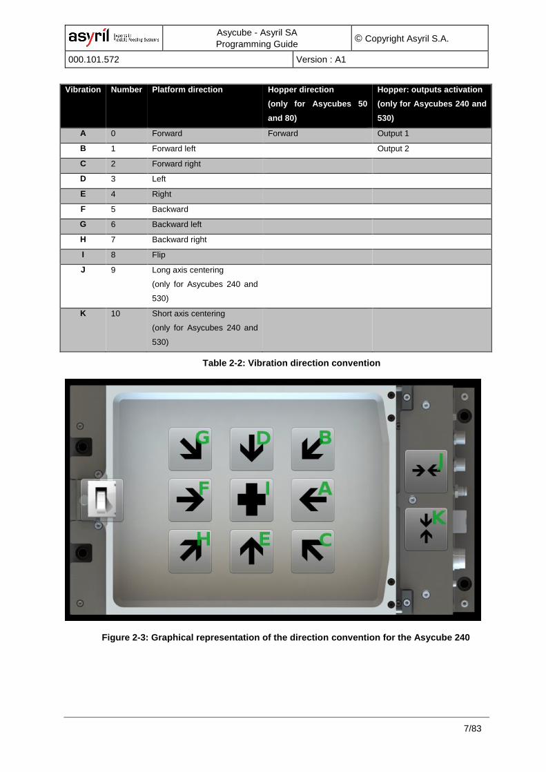
2.1. Vibration convention
The Asycube has 26 different vibrations, named from ‘A’ to ‘Z’. As a convention, some of the
vibrations are set for a given direction while the others can be used for custom vibrations.
The Table 2-2 presents the convention used in the Asycubes (please be aware of the
differences between the Asycubes models). The Figure 2-3 presents graphically the
convention for an Asycube.
Asycube - Asyril SA
Programming Guide © Copyright Asyril S.A.
000.101.572 Version : A1
7/83
Vibration Number Platform direction Hopper direction
(only for Asycubes 50
and 80)
Hopper: outputs activation
(only for Asycubes 240 and
530)
A 0 Forward Forward Output 1
B 1 Forward left Output 2
C 2 Forward right
D 3 Left
E 4 Right
F 5 Backward
G 6 Backward left
H 7 Backward right
I 8 Flip
J 9 Long axis centering
(only for Asycubes 240 and
530)
K 10 Short axis centering
(only for Asycubes 240 and
530)
Table 2-2: Vibration direction convention
Figure 2-3: Graphical representation of the direction convention for the Asycube 240

Asycube - Asyril SA
Programming Guide © Copyright Asyril S.A.
000.101.572 Version : A1
8/83
2.2. Vibration sets
The vibration parameters are organized in vibration sets. There are 26 different vibration sets
(the 26th is reserved for Asyril technician).
Each of the vibration set contains 26 vibrations for the platform identified by letters A to Z and
26 outputs activations (to control two hoppers) identified by other letters A to Z.
For the platform, the 11 first vibrations (A to K) are by convention used for standard vibrations
(movements forward, backward, left, right, flip, long axis centering, etc).
For the Asycubes 50 and 80 which have an integrated hopper, the first hopper vibration is by
convention used for standard vibration ‘Forward’.
The Asycubes 240 and 530 do not have integrated hoppers but outputs that can be activated
to control an external hopper. For the outputs activations, the 2 first activations are by
convention used for standard activations (A activate the output 1 and B the output 2).
The table below shows the organization of the vibration sets:
Vibration Sets
1 to 26
ID 26
Platform Vibration
Page 1B
C
D
E
F
Forward
Forward left
Forward right
Left
Right
Backward
A
G Backward left
H Backward right
I Flip
Page 1K
L
M
N
O
Custom
Custom
Custom
Custom
Custom
Custom
J
P Custom
Q Custom
R Custom
S
T
U
V
Custom
Custom
Custom
Custom
W Custom
X Custom
Y Custom
Z Custom
Custom
Output activation
Page 1B
C
D
E
F
Output 1
Output 2
Custom
Custom
Custom
Custom
A
G Custom
H Custom
I Custom
Page 1K
L
M
N
O
Custom
Custom
Custom
Custom
Custom
Custom
J
P Custom
Q Custom
R Custom
S
T
U
V
Custom
Custom
Custom
Custom
W Custom
X Custom
Y Custom
Z Custom
Custom
ID 1
Platform Vibration
Page 1B
C
D
E
F
Forward
Forward left
Forward right
Left
Right
Backward
A
G Backward left
H Backward right
I Flip
Page 1K
L
M
N
O
Custom
Custom
Custom
Custom
Custom
Custom
J
P Custom
Q Custom
R Custom
S
T
U
V
Custom
Custom
Custom
Custom
W Custom
X Custom
Y Custom
Z Custom
Custom
Output activation
Page 1B
C
D
E
F
Output 1
Output 2
Custom
Custom
Custom
Custom
A
G Custom
H Custom
I Custom
Page 1K
L
M
N
O
Custom
Custom
Custom
Custom
Custom
Custom
J
P Custom
Q Custom
R Custom
S
T
U
V
Custom
Custom
Custom
Custom
W Custom
X Custom
Y Custom
Z Custom
Custom
Stan
dar
d
Vib
rati
on
s
Stan
dar
d
Act
ivat
ion
s
Figure 2-4 : description of vibration sets

Asycube - Asyril SA
Programming Guide © Copyright Asyril S.A.
000.101.572 Version : A1
9/83
2.3. Sequences
The Asycube contains 26 different sequences (the 26th is reserved for Asyril technician). Each
sequence contains 7 customizable actions. It can be none (no action), platform vibration,
output activation or stabilization (a delay).
Sequences
ID 1
Page 1
Action 2
Action 3
Action 4
Action 5
Action 6
Action 1
Action 7
ID 2
Page 1
Action 2
Action 3
Action 4
Action 5
Action 6
Action 1
Action 7
ID 26
Page 1
Action 2
Action 3
Action 4
Action 5
Action 6
Action 1
Action 7
1 to 26
Figure 2-5 : description of sequences
More details in the commands descriptions.
2.4. Load/save in memories
Because of the size of the volatile memory, it can only contain one of the 26 vibration sets. At
startup, the Asycube loads from flash memory the last selected vibration set, the 26
sequences and the global parameters.
When the user selects another vibration set, the parameters are loaded from the flash memory
and overwrite the previously selected vibration set (all modifications made before selecting
another vibration set are lost if the user did not save the vibration set with the command {DV},
which saves the vibration parameters in the flash memory). A status indicates if a value has
been modified and can be read with the command {?50}. The time needed to load a new
vibration set from the flash memory to the volatile memory is approximatively 0.3 seconds.
Every 20 minutes, the global parameters are automatically saved. If the user tries to save
during this ongoing process, his command will be refused until the automatic saving is
finished.

Asycube - Asyril SA
Programming Guide © Copyright Asyril S.A.
000.101.572 Version : A1
10/83
3. How to use the Asycube
This chapter gives the main information about the use and tuning of the Asycube. It shows
general information and behavior, presents the main procedure from setup to running in
production with an Asycube and describes then each step. The next chapters will detail the
chosen working mode.
3.1. Integration modes
Different ways of integration are available. Here below is a brief description of the main ones.
More information is then available in the corresponding section. The main tasks necessary to
use, configure and integrate the Asycube are described depending the chosen integration
mode. The next tables and figures describe the tasks in charge of the Asycube and the ones
due to the integrator. The light blue color represents the levels offered by Asyril, the white
one the levels in charge of the integrator.

Asycube - Asyril SA
Programming Guide © Copyright Asyril S.A.
000.101.572 Version : A1
11/83
3.1.1. Direct connection to the Asycube, configuration with Asycube HMI
In this integration mode, the integrator uses the Asycube HMI (installed on a computer, the
same as the integrator system or another one) to configure the Asycube, and communicates
with the Asycube from his own system in order to execute the vibrations. All the
configurations are made with the Asycube HMI and can be exported in different types of files
(*.fconf and *.fseqfiles).
HMI PC (can be the same as controller)
PC
Controller
Asycube HMI
.fconf
.fseq
CAMERA
ROBOT
.dll
ASYCUBE
Firmw
are
LEVEL TASKS
Asycube Generation and synchronization of the desired vibration
Execute sequences
Save and reload 25 vibration sets (26 for the reload)
Save and reload 25 sequences (26 for the reload)
Activation of the outputs and backlight
Choice/Management of the optimal sequence based on the vision feedback
Asycube HMI Configuration and optimization of the feeding (vibration) parameters
Configuration and optimization of the sequences
Integrator Communication with the Asycube
Recipe management (memorize vibration set ID and sequence ID for each
component).
Synchronization of the feeder and the machine
Optional Treatment of the recipe (read/write parameters)
Table 3-1: Integration mode: Asycube only

Asycube - Asyril SA
Programming Guide © Copyright Asyril S.A.
000.101.572 Version : A1
12/83
3.1.2. Direct connection to the Asycube
In this integration mode, the integrator develops his own HMI to configure the Asycube and
communicates with the Asycube from his own system in order to execute the vibrations.
PC
Controller
Customer HMI Customer HMI
CAMERA
ROBOT
ASYCUBE
Firmw
are
recipe
LEVEL TASKS
Asycube Generation and synchronization of the desired vibration
Execute sequences
Save and reload 25 vibration sets (26 for the reload)
Save and reload 25 sequences (26 for the reload)
Activation of the outputs and backlight
Choice/Management of the optimal sequence based on the vision feedback
Integrator Communication with the Asycube
Recipe management (memorize vibration set ID and sequence ID for each
component).
Configuration and optimization of the feeding (vibration) parameters
(customer HMI)
Configuration and optimization of the sequences (customer HMI)
Synchronization of the feeder and the machine
Optional Treatment of the recipe (read/write parameters)
Table 3-2: Integration mode: Asycube only

Asycube - Asyril SA
Programming Guide © Copyright Asyril S.A.
000.101.572 Version : A1
13/83
3.1.3. Connection to the Asycube with the Plugin .NET and configuration with Asyril HMI
In this integration mode, the integrator uses the Asycube HMI (installed on a computer, the
same as the integrator system or another one) to configure the Asycube and communicates
with the Asycube from his own system in order to execute the vibrations by using the
Asycube Plugin .NET. This Plugin simplifies the development and allows to export and import
the same recipe files as in the Asycube HMI.
PC
Controller
.dll
Asycube HMI
.fconf
.fseq
CAMERA
ROBOT
.dllASYCUBE
Firmw
are
LEVEL TASKS
Asycube Generation and synchronization of the desired vibration
Execute sequences
Save and reload 25 vibration sets (26 for the reload)
Save and reload 25 sequences (26 for the reload)
Activation of the outputs and backlight
Choice/Management of the optimal sequence based on the vision
feedback
Asycube Plugin
.NET
Communication with the Asycube (access to the parameters of the
vibrations and sequences, vibrations and sequences execution, etc)
Treatment of the recipe (read/write parameters)
Asycube HMI Configuration and optimization of the feeding (vibration) parameters
Configuration and optimization of the sequences
Integrator Synchronization of the feeder and the machine
Recipe management (memorize vibration set ID and sequence ID for
each component).
Table 3-3: Integration mode: Asycube with Plugin .NET and HMI

Asycube - Asyril SA
Programming Guide © Copyright Asyril S.A.
000.101.572 Version : A1
14/83
3.1.4. Connection to the Asycube with the Plugin .NET and configuration with the customer user interface using the Plugin .NET
In this integration mode, the integrator uses the Asycube Plugin .NET to communicate with
the Asycube and creates his own HMI to configure the vibrations, the sequences, etc. By
choosing this integration mode, the integrator can design his own HMI and benefits from the
simplification brought by the Plugin .NET.
Customer HMICustomer HMI
PC
Controller
.dll
CAMERA
ROBOT
ASYCUBE
Firmw
are
.fconf
.fseq
LEVEL TASKS
Asycube Generation and synchronization of the desired vibration
Execute sequences
Save and reload 25 vibration sets (26 for the reload)
Save and reload 25 sequences (26 for the reload)
Activation of the outputs and backlight
Choice/Management of the optimal sequence based on the vision
feedback
Asycube Plugin
.NET
Communication with the Asycube (access to the parameters of the
vibrations and sequences, vibrations and sequences execution, etc)
Treatment of the recipe (read/write parameters)
Integrator Configuration and optimization of the feeding (vibration) parameters (HMI)
Configuration and optimization of the sequences
Synchronization of the feeder and the machine
Recipe management (memorize vibration set ID and sequence ID for
each component).
Table 3-4: Integration mode: Asycube Plugin .NET

Asycube - Asyril SA
Programming Guide © Copyright Asyril S.A.
000.101.572 Version : A1
15/83
3.1.5. Modbus TCP connection with the Asycube, configuration with Asycube HMI
In this integration mode, the integrator uses the Asycube HMI to configure the Asycube from
an external PC (e.g. Laptop). The integrator communicates with the Asycube from his own
system (e.g. PLC) through Modbus TCP in order to execute the vibrations. Please refer to
Chapter 6 for more information on Modbus TCP. As an option, a gateway can be used to
convert the Asycube Modbus TCP data to industrial fieldbus data for the controller.
HMI PC (can be the same as controller)
PC
Controller
Asycube HMI
.fconf
.fseq
CAMERA
ROBOT
.dll
ASYCUBE
Firmw
are
MODBUS TCP
LEVEL TASKS
Asycube Generation and synchronization of the desired vibration
Execute sequences
Save and reload 25 vibration sets (26 for the reload)
Save and reload 25 sequences (26 for the reload)
Activation of the outputs and backlight
Choice/Management of the optimal sequence based on the vision feedback
Asycube HMI Configuration and optimization of the feeding (vibration) parameters
Configuration and optimization of the sequences
Integrator Communication with the Asycube
Recipe management (memorize vibration set ID and sequence ID for each
component).
Synchronization of the feeder and the machine
Optional Treatment of the recipe (read/write parameters)
Table 3-5: Integration mode: Asycube only

Asycube - Asyril SA
Programming Guide © Copyright Asyril S.A.
000.101.572 Version : A1
16/83
3.2. Production cycle with sequences
Follow this diagram to work with Asycube and sequences in direct communication.
Start production
Select the vibrations set
Select the sequence depending of number of
parts on the surface
Select the vibrations set : {UV1}
Select the sequence : {US1}
Image acquisition and analyse
Parts to take?
Take parts on platform
Execute the sequence Execute sequence : {ES:(10;50;-0.100;0.130;1)}
Wait sequence finished
Return the sequence duration
Wait the time value received from the ExecuteSequence method
no
yes
Figure 3-6 : description of sequences
For details of the different parameters, see the complete description of the commands below
in this documentation.

Asycube - Asyril SA
Programming Guide © Copyright Asyril S.A.
000.101.572 Version : A1
17/83
3.3. Questions and answers
Here are some recurrent questions and their answers for the integration with TCP/IP
communication.
3.3.1. Which vibration set or sequence is currently selected?
To know which vibration set is selected, use the command {UV?}.
For the selected sequence, use the command {US?}.
3.3.2. How do I know if some parameters of the current vibration set have been modified?
To obtain the state of the selected vibration set, use the command {?50}. If the
returned value is 1, parameters have been modified.
3.3.3. What is the duration of a specific sequence?
The duration of a sequence (or a centering and feeding) is returned by the execution
function. For example, the command {ES:(10;20;-0.1;0.8;1)} will receive as answer
the string {ES:(10;20;-0.1;0.8;1;1830)} and 1830 is the duration of the sequence in
milliseconds.
3.3.4. How do I know when a vibration or a sequence is finished?
For the vibration, the remaining time of the platform vibration is given by the answer
of the command {?42}. For the hopper, use the command {?44} and for the
sequence {?46}. The value returned indicates the remaining time in milliseconds.
3.3.5. How do I backup all vibration set on the computer?
If you do not use the Asycube HMI, you have to read all the vibration parameters
vibration by vibration and save the received data in a file. For example, use the
command {LCA} for the vibration A. The returned values correspond to the
parameters of this vibration (amplitude of actuator 1, frequency of actuator 1, etc)
For the hopper vibration A, the corresponding command is {LBA}.

Asycube - Asyril SA
Programming Guide © Copyright Asyril S.A.
000.101.572 Version : A1
18/83
3.3.6. How is the center of mass of the components on the platform transferred to the command ES ?
The positions on the platform are normalized between -1 and +1 in both directions in
order to be independent of the resolution of the camera or of the choice of the
camera manufacturer image orientation and origin.
This figure explains the standardized range:
Check in your camera specifications to find the correspondence between the
camera positions and the Asycube standardized range.

Asycube - Asyril SA
Programming Guide © Copyright Asyril S.A.
000.101.572 Version : A1
19/83
4. Asycubes Parameters
This chapter presents the Asycube parameters used to configure the settings and to
configure the vibrations and sequences. These parameters values can be accessed using the
dedicated text commands (Section 5.4.3). Some of these parameters values can be
accessed through Modbus TCP (Chapter 6).
NOTE :
Some parameters values have a range of validity. For example, the Amplitude 1 of the
Platform vibration "A" (Address 300) ranges from 0 to 100. If you try to set a value out of this
range (e.g. 120), it will be limited to its boundary (i.e. 100) without generating an error
message. Some of a thresholds may be defined in another parameter. For example, the
backlight intensity (Backlight PWM, Address 102) has a minimal value defined in the
Backlight minimum PWM threshold parameter (Address 104).
4.1. Configuration
*: integrator write; **: developer write
Address Parameters Command Comment
2 warning rd & clear
4 alarm rd & clear
6 password wr
…
22 life time [day] ** if auto-flashing enabled
24 life time [hour] ** if auto-flashing enabled
26 life time [second] ** if auto-flashing enabled
28 auto-flashing 20Min. * default: enable
30 actuators life time [hour] **
32 actuators life time [sec] **
34 actuators life time [msec] **
36 Actuators number of vibrations
[nb] – 0-32767
** first 2 bytes
38 Actuators number of vibrations
[nb] – i*32768
** bytes 3 and 4
40 IP address first byte * default: 192
42 IP address second byte * default: 168
44 IP address third byte * default: 127
46 IP address fourth byte * default: 254
48 IP subnet mask first byte * default: 255

Asycube - Asyril SA
Programming Guide © Copyright Asyril S.A.
000.101.572 Version : A1
20/83
Address Parameters Command Comment
50 IP subnet mask second byte * default: 255
52 IP subnet mask third byte * default: 255
54 IP subnet mask fourth byte * default: 0
56 TCP port * default: 4001
…
60 number of flash in ROM [nb] –
0-32767
** number of flashing data in ROM
62 number of flash in ROM [nb] –
i*32768
** number of flashing data in ROM for more
than 32767
64 average number of flash in
ROM [nb/day]
** number of flashing data in ROM per day
…
72 Synchro backlight logic * 0 : logic positive / 1 : logic negative
…
80 DIP switch 1 ON ** switch state: 1 : IP default value
82 DIP switch 2 ON **
84 DIP switch 3 ON **
86 DIP switch 4 ON **
…
92 Type 1: Asycube ** 0 : Unknown
1: Asycube 50
2: Asycube 80
3: Asycube 130
4: Asycube 240
5: Asycube 530
94 Type 2: Asycube **
96 Color of Backlight * 0: Green
1: Red
2: Blue
3: IR
4: UV
5: White
99: None
…
100 Backlight Flash Time [ms]
102 Backlight PWM [%]
104 Backlight minimum PWM
threshold
** [%]
106 Frequency minimum threshold ** [Hz]
108 Frequency maximum
threshold
** [Hz]

Asycube - Asyril SA
Programming Guide © Copyright Asyril S.A.
000.101.572 Version : A1
21/83
Address Parameters Command Comment
110 Vibration Set ID ** Selected Vibration Set ID [1...26]
112 Sequence ID ** Selected Sequence ID [1...26]
…
130 Sequence ID Input 1 Sequence ID [1...26]
132 Sequence ID Input 2 Sequence ID [1...26]
…
144 UART1 rx timeout Ethernet * Default: 1'000 [ms]
148 UART1 tx timeout Ethernet * Default: 2 [ms]
…
152 Backlight timeout ** 0= disable timeout function
30 = 30 sec with PWM 100%, 60 sec with
PWM 50%, etc.
0 for Asycubes 240 and 530 backlight
because there is no risk to keep it switched
on permanently.
…
158 Gain amplitude actuator 1 * (int) [2.55]
160 Gain amplitude actuator 2 * (int) [2.55]
162 Gain amplitude actuator 3 * (int) [2.55]
164 Gain amplitude actuator 4 * (int) [2.55]
166 Offset amplitude actuator 1 * (int) +/- n 1/256
168 Offset amplitude actuator 2 * (int) +/- n 1/256
170 Offset amplitude actuator 3 * (int) +/- n 1/256
172 Offset amplitude actuator 4 * (int) +/- n 1/256
174 Offset frequency actuator 1 * (int) +/- n 0.25 Hz
176 Offset frequency actuator 2 * (int) +/- n 0.25 Hz
178 Offset frequency actuator 3 * (int) +/- n 0.25 Hz
180 Offset frequency actuator 4 * (int) +/- n 0.25 Hz
182 Gain amplitude output 1 * (int) [2.55]
184 Gain amplitude output 2 * (int) [2.55]
186 Offset amplitude output 1 * (int) +/- n 1/256
188 Offset amplitude output 2 * (int) +/- n 1/256
190 Output 1 logic * 0 : logic positive / 1 : logic negative
192 Output 2 logic * 0 : logic positive / 1 : logic negative
194 Input 1 logic * 0 : logic positive / 1 : logic negative
196 Input 2 logic * 0 : logic positive / 1 : logic negative
Table 4-1: configuration parameters

Asycube - Asyril SA
Programming Guide © Copyright Asyril S.A.
000.101.572 Version : A1
22/83
4.2. Platform Vibrations
This section presents the platform vibration parameters. Please note that these parameters
are different between the Asycubes 50 and 80 (Section 4.2.1) and the Asycubes 240 and 530
(4.2.2).
4.2.1. For the Asycube 50 and Asycube 80
The Table 4-2 shows the formula to get the addresses of the platform vibrations parameters,
while the Table 4-3 presents the specific addresses for the vibrations A and B. These
parameters are set from address range 300 to 920 and from 940 to 990.
Address Parameters Vibration Units Range
300+24*n Amplitude 1 Platform "n"
A: n=0,
B: n=1,
…
Z: n=25
[%] 0 to 100 %
302+24*n Frequency 1 [Hz] 0 to 250 Hz
304+24*n Phase 1 [°deg.] 0 to 359 degrees
306+24*n Waveform 1 [0..3] 0=no signal, 1=sinus, 2=rp up, 3= rp dn
308+24*n Amplitude 2 [%] 0 to 100 %
310+24*n Frequency 2 [Hz] 0 to 250 Hz
312+24*n Phase 2 [°deg.] 0 to 359 degrees
314+24*n Waveform 2 [0..3] 0=no signal, 1=sinus, 2=rp up, 3= rp dn
316+24*n Amplitude 3 [%] 0 to 100 %
318+24*n Frequency 3 [Hz] 0 to 250 Hz
320+24*n Waveform 3 [0..3] 0=no signal, 1=sinus, 2=rp up, 3= rp dn
940+2*n Duration [ms] 0 to 30’000 ms
Table 4-2: Generic addressing of platform vibrations parameters for the Asycube 50
and Asycube 80
Address Parameters Vibration Units Range
300 Amplitude 1 Platform "A" [%] 0 to 100 %
302 Frequency 1 [Hz] 0 to 250 Hz
304 Phase 1 [°deg.] 0 to 359 degrees
306 Waveform 1 [0..3] 0=no signal, 1=sinus, 2=rp up, 3= rp dn
308 Amplitude 2 [%] 0 to 100 %
310 Frequency 2 [Hz] 0 to 250 Hz
312 Phase 2 [°deg.] 0 to 359 degrees

Asycube - Asyril SA
Programming Guide © Copyright Asyril S.A.
000.101.572 Version : A1
23/83
Address Parameters Vibration Units Range
314 Waveform 2 [0..3] 0=no signal, 1=sinus, 2=rp up, 3= rp dn
316 Amplitude 3 [%] 0 to 100 %
318 Frequency 3 [Hz] 0 to 250 Hz
320 Waveform 3 [0..3] 0=no signal, 1=sinus, 2=rp up, 3= rp dn
940 Duration [ms] 0 to 30’000 ms
324 Amplitude 1 Platform "B" [%] 0 to 100 %
326 Frequency 1 [Hz] 0 to 250 Hz
328 Phase 1 [°deg.] 0 to 359 degrees
330 Waveform 1 [0..3] 0=no signal, 1=sinus, 2=rp up, 3= rp dn
332 Amplitude 2 [%] 0 to 100 %
334 Frequency 2 [Hz] 0 to 250 Hz
336 Phase 2 [°deg.] 0 to 359 degrees
338 Waveform 2 [0..3] 0=no signal, 1=sinus, 2=rp up, 3= rp dn
340 Amplitude 3 [%] 0 to 100 %
342 Frequency 3 [Hz] 0 to 250 Hz
344 Waveform 3 [0..3] 0=no signal, 1=sinus, 2=rp up, 3= rp dn
942 Duration [ms] 0 to 30’000 ms
Table 4-3: platform vibrations parameters A and B for the Asycube 50 and Asycube 80
4.2.2. For the Asycube 240 and Asycube 530
The Table 4-4 shows the formula to get the addresses of the platform vibrations parameters,
while the Table 3-1 presents the specific addresses for the vibrations A and B. These
parameters are set from address range 300 to 1962.
Address Parameters Vibration Units Range
300+64*n Amplitude 1 Platform "n"
A: n=0,
B: n=1,
…
Z: n=25
[%] 0 to 100 %
302+64*n Frequency 1 [Hz] 0 to 250 Hz
304+64*n Phase 1 [°deg.] 0 to 359 degrees
306+64*n Waveform 1 [0..3] 0=no signal, 1=sinus, 2=rp up, 3= rp dn
310+64*n Amplitude 2 [%] 0 to 100 %
312+64*n Frequency 2 [Hz] 0 to 250 Hz
314+64*n Phase 2 [°deg.] 0 to 359 degrees

Asycube - Asyril SA
Programming Guide © Copyright Asyril S.A.
000.101.572 Version : A1
24/83
Address Parameters Vibration Units Range
316+64*n Waveform 2 [0..3] 0=no signal, 1=sinus, 2=rp up, 3= rp dn
320+64*n Amplitude 3 [%] 0 to 100 %
322+64*n Frequency 3 [Hz] 0 to 250 Hz
324+64*n Phase 3 [°deg.] 0 to 359 degrees
326+64*n Waveform 3 [0..3] 0=no signal, 1=sinus, 2=rp up, 3= rp dn
330+64*n Amplitude 4 [%] 0 to 100 %
332+64*n Frequency 4 [Hz] 0 to 250 Hz
334+64*n Phase 4 [°deg.] 0 to 359 degrees
336+64*n Waveform 4 [0..3] 0=no signal, 1=sinus, 2=rp up, 3= rp dn
362+64*n Duration [ms] 0 to 30’000 ms
Table 4-4: Generic addressing of the platform vibrations parameters for the Asycube
240 and Asycube 530
Address Parameters Vibration Units Range
300 Amplitude 1 Platform "A" [%] 0 to 100 %
302 Frequency 1 [Hz] 0 to 250 Hz
304 Phase 1 [°deg.] 0 to 359 degrees
306 Waveform 1 [0..3] 0=no signal, 1=sinus, 2=rp up, 3= rp dn
310 Amplitude 2 [%] 0 to 100 %
312 Frequency 2 [Hz] 0 to 250 Hz
314 Phase 2 [°deg.] 0 to 359 degrees
316 Waveform 2 [0..3] 0=no signal, 1=sinus, 2=rp up, 3= rp dn
320 Amplitude 3 [%] 0 to 100 %
322 Frequency 3 [Hz] 0 to 250 Hz
324 Phase 3 [°deg.] 0 to 359 degrees
326 Waveform 3 [0..3] 0=no signal, 1=sinus, 2=rp up, 3= rp dn
330 Amplitude 4 [%] 0 to 100 %
332 Frequency 4 [Hz] 0 to 250 Hz
334 Phase 4 [°deg.] 0 to 359 degrees
336 Waveform 4 [0..3] 0=no signal, 1=sinus, 2=rp up, 3= rp dn
362 Duration [ms] 0 to 30’000 ms
364 Amplitude 1 Platform "B" [%] 0 to 100 %
366 Frequency 1 [Hz] 0 to 250 Hz
368 Phase 1 [°deg.] 0 to 359 degrees
370 Waveform 1 [0..3] 0=no signal, 1=sinus, 2=rp up, 3= rp dn

Asycube - Asyril SA
Programming Guide © Copyright Asyril S.A.
000.101.572 Version : A1
25/83
Address Parameters Vibration Units Range
374 Amplitude 2 [%] 0 to 100 %
376 Frequency 2 [Hz] 0 to 250 Hz
378 Phase 2 [°deg.] 0 to 359 degrees
380 Waveform 2 [0..3] 0=no signal, 1=sinus, 2=rp up, 3= rp dn
384 Amplitude 3 [%] 0 to 100 %
386 Frequency 3 [Hz] 0 to 250 Hz
388 Phase 3 [°deg.] 0 to 359 degrees
390 Waveform 3 [0..3] 0=no signal, 1=sinus, 2=rp up, 3= rp dn
394 Amplitude 4 [%] 0 to 100 %
396 Frequency 4 [Hz] 0 to 250 Hz
398 Phase 4 [°deg.] 0 to 359 degrees
400 Waveform 4 [0..3] 0=no signal, 1=sinus, 2=rp up, 3= rp dn
426 Duration [ms] 0 to 30’000 ms
Table 4-5: platform vibrations parameters A and B for the Asycube 240 and Asycube
530

Asycube - Asyril SA
Programming Guide © Copyright Asyril S.A.
000.101.572 Version : A1
26/83
4.3. Hopper Vibrations or Outputs Activations
This section presents the hopper vibration parameters for the Asycubes 50 and 80 and the
output activations parameters for the Asycubes 240 and 530.
4.3.1. Hopper vibrations (Asycube 50 and Asycube 80)
The Table 4-6 shows the formula to get the addresses of the hopper vibrations parameters,
while the Table 4-7 presents the specific addresses for the vibrations A and B. These
parameters are set from address range 1000 to 1204 and 1240 to 1290.
Address Parameters Vibration Units Range
1000+8*n Amplitude Bulk "n"
A: n=0,
B: n=1,
…
Z: n=25
[%] 0 to 100%
1002+8*n Frequency [Hz] 0 to 250 Hz
1004+8*n Figure [0..3] 0=no signal, 1=sinus, 2=rp up, 3= rp dn
1240+2*n Duration [ms] 0 to 30’000 ms
Table 4-6: Generic addressing of the hopper vibrations parameters for the Asycube 50
and Asycube 80
Address Parameters Vibration Units Range
1000 Amplitude Bulk "A" [%] 0 to 100%
1002 Frequency [Hz] 0 to 250 Hz
1004 Figure [0..3] 0=no signal, 1=sinus, 2=rp up, 3= rp dn
1240 Duration [ms] 0 to 30’000 ms
1008 Amplitude Bulk "B" [%] 0 to 100%
1010 Frequency [Hz] 0 to 250 Hz
1012 Figure [0..3] 0=no signal, 1=sinus, 2=rp up, 3= rp dn
1242 Duration [ms] 0 to 30’000 ms
Table 4-7: hopper vibrations parameters A and B for the Asycube 50 and Asycube 80

Asycube - Asyril SA
Programming Guide © Copyright Asyril S.A.
000.101.572 Version : A1
27/83
4.3.2. Outputs activations (Asycube 240 and Asycube 530)
The Table 4-8 shows the formula to get the addresses of the outputs activations parameters,
while the presents the specific addresses for the outputs activations A and B. These
parameters are set from address range 2000 to 2414.
Address Parameters Activation Units Range
2000+16*n Toggle output 1 Outputs "n"
A: n=0,
B: n=1,
…
Z: n=25
[bool] 0=no signal, 1=signal
2002+16*n Amplitude output 1 [%] 0 to 100% (0 to 10V)
2004+16*n Toggle output 2 [bool] 0=no signal, 1=signal
2006+16*n Amplitude output 2 [%] 0 to 100% (0 to 10V)
2014+16*n Duration [ms] 0 to 30’000 ms
Table 4-8: Generic addressing of the outputs activations parameters for the Asycube
240 and Asycube 530
Address Parameters Activation Units Range
2000 Toggle output 1 Outputs "A" [bool] 0=no signal, 1=signal
2002 Amplitude output 1 [%] 0 to 100% (0 to 10V)
2004 Toggle output 2 [bool] 0=no signal, 1=signal
2006 Amplitude output 2 [%] 0 to 100% (0 to 10V)
2014 Duration [ms] 0 to 30’000 ms
2016 Toggle output 1 Outputs "B" [bool] 0=no signal, 1=signal
2018 Amplitude output 1 [%] 0 to 100% (0 to 10V)
2020 Toggle output 2 [bool] 0=no signal, 1=signal
2022 Amplitude output 2 [%] 0 to 100% (0 to 10V)
2030 Duration [ms] 0 to 30’000 ms
Table 4-9: outputs activations parameters A and B for the Asycube 240 and Asycube
530

Asycube - Asyril SA
Programming Guide © Copyright Asyril S.A.
000.101.572 Version : A1
28/83
4.4. Sequences
This section presents the sequences parameters.
The Table 4-10 shows the formula to get the address of the sequences parameters; please
be aware that the base address differs from an Asycube model to the others (baseAddr =
1300 for the Asycubes 50 and 80; baseAddr = 2500 for the Asycubes 240 and 530). The
presents the specific addresses of all 7 actions from the sequences 1 and 26. These
parameters are set from address range 1300 to 2806 for the Asycubes 50 and 80 while they
are set from address range 2500 to 4006 for the Asycube 240 and 530.
Address Parameters Action nb Sequence ID Range Comment
baseAddr
+ 0
+ 8*(m-1)
+ 58*(n-1)
Type m
1 to 7
n
1 to 25
26**
[0..3] 0=None, 1=Platform 2=Hopper,
3=Stabilisation
baseAddr
+ 2
+ 8*(m-1)
+ 58*(n-1)
Vibration m n [A..Z + 0] 0 = Centering
baseAddr
+ 4
+ 8*(m-1)
+ 58*(n-1)
Duration Mode m n [0..2] 0=Fixed, 1=QuantityAdjusted,
2=VibrationRatio
baseAddr
+ 6
+ 8*(m-1)
+ 58*(n-1)
Duration Value m n [0..30000ms]
[0..100%]
Unit change depending of selected
duration mode
**: developer write
Table 4-10: Generic addressing of the sequences parameters (baseAddr = 1300 for the
Asycubes 50 and 80; baseAddr = 2500 for the Asycubes 240 and 530)
Address Parameters Action nb Sequence ID Range Comment
2500 Type 1 1 [0..3] 0=None, 1=Platform 2=Hopper,
3=Stabilisation
2502 Vibration [A..Z + 0] 0 = Centering
2504 Duration Mode [0..2] 0=Fixed, 1=QuantityAdjusted,
2=VibrationRatio
2506 Duration Value [0..30000ms]
[0..100%]
Unit change depending of selected
duration mode
2508 Type 2 1 [0..3] 0=None, 1=Platform 2=Hopper,
3=Stabilisation

Asycube - Asyril SA
Programming Guide © Copyright Asyril S.A.
000.101.572 Version : A1
29/83
Address Parameters Action nb Sequence ID Range Comment
2510 Vibration [A..Z + 0] 0 = Centering
2512 Duration Mode [0..2] 0=Fixed, 1=QuantityAdjusted,
2=VibrationRatio
2514 Duration Value [0..30000ms]
[0..100%]
Unit change depending of selected
duration mode
2516 Type 3 1 [0..3] 0=None, 1=Platform 2=Hopper,
3=Stabilisation
2518 Vibration [A..Z + 0] 0 = Centering
2520 Duration Mode [0..2] 0=Fixed, 1=QuantityAdjusted,
2=VibrationRatio
2522 Duration Value [0..30000ms]
[0..100%]
Unit change depending of selected
duration mode
2524 Type 4 1 [0..3] 0=None, 1=Platform 2=Hopper,
3=Stabilisation
2526 Vibration [A..Z + 0] 0 = Centering
2528 Duration Mode [0..2] 0=Fixed, 1=QuantityAdjusted,
2=VibrationRatio
2530 Duration Value [0..30000ms]
[0..100%]
Unit change depending of selected
duration mode
2532 Type 5 1 [0..3] 0=None, 1=Platform 2= Hopper,
3=Stabilisation
2534 Vibration [A..Z + 0] 0 = Centering
2536 Duration Mode [0..2] 0=Fixed, 1=QuantityAdjusted,
2=VibrationRatio
2538 Duration Value [0..30000ms]
[0..100%]
Unit change depending of selected
duration mode
2540 Type 6 1 [0..3] 0=None, 1=Platform 2= Hopper,
3=Stabilisation
2542 Vibration [A..Z + 0] 0 = Centering
2544 Duration Mode [0..2] 0=Fixed, 1=QuantityAdjusted,
2=VibrationRatio
2546 Duration Value [0..30000ms]
[0..100%]
Unit change depending of selected
duration mode
2548 Type 7 1 [0..3] 0=None, 1=Platform 2= Hopper,
3=Stabilisation

Asycube - Asyril SA
Programming Guide © Copyright Asyril S.A.
000.101.572 Version : A1
30/83
Address Parameters Action nb Sequence ID Range Comment
2550 Vibration [A..Z + 0] 0 = Centering
2552 Duration Mode [0..2] 0=Fixed, 1=QuantityAdjusted,
2=VibrationRatio
2554 Duration Value [0..30000ms]
[0..100%]
Unit change depending of selected
duration mode
2556 Nb Limit Parts 1 [0..32767] Nb limit of parts for the
QuantityAdjusted vibration.
3950 Type 1 26 ** [0..3] 0=None, 1=Platform 2= Hopper,
3=Stabilisation
3952 Vibration ** [A..Z + 0] 0 = Centering
3954 Duration Mode ** [0..2] 0=Fixed, 1=QuantityAdjusted,
2=VibrationRatio
3956 Duration Value ** [0..30000ms]
[0..100%]
Unit change depending of selected
duration mode
3958 Type 2 26 ** [0..3] 0=None, 1=Platform 2= Hopper,
3=Stabilisation
3960 Vibration ** [A..Z + 0] 0 = Centering
3962 Duration Mode ** [0..2] 0=Fixed, 1=QuantityAdjusted,
2=VibrationRatio
3964 Duration Value ** [0..30000ms]
[0..100%]
Unit change depending of selected
duration mode
3966 Type 3 26 ** [0..3] 0=None, 1=Platform 2= Hopper,
3=Stabilisation
3968 Vibration ** [A..Z + 0] 0 = Centering
3970 Duration Mode ** [0..2] 0=Fixed, 1=QuantityAdjusted,
2=VibrationRatio
3972 Duration Value ** [0..30000ms]
[0..100%]
Unit change depending of selected
duration mode
…
3974 Type 4 26 ** [0..3] 0=None, 1=Platform 2= Hopper,
3=Stabilisation
3976 Vibration ** [A..Z + 0] 0 = Centering
3978 Duration Mode ** [0..2] 0=Fixed, 1=QuantityAdjusted,
2=VibrationRatio

Asycube - Asyril SA
Programming Guide © Copyright Asyril S.A.
000.101.572 Version : A1
31/83
Address Parameters Action nb Sequence ID Range Comment
3980 Duration Value ** [0..30000ms]
[0..100%]
Unit change depending of selected
duration mode
3982 Type 5 26 ** [0..3] 0=None, 1=Platform 2= Hopper,
3=Stabilisation
3984 Vibration ** [A..Z + 0] 0 = Centering
3986 Duration Mode ** [0..2] 0=Fixed, 1=QuantityAdjusted,
2=VibrationRatio
3988 Duration Value ** [0..30000ms]
[0..100%]
Unit change depending of selected
duration mode
3990 Type 6 26 ** [0..3] 0=None, 1=Platform 2= Hopper,
3=Stabilisation
3992 Vibration ** [A..Z + 0] 0 = Centering
3994 Duration Mode ** [0..2] 0=Fixed, 1=QuantityAdjusted,
2=VibrationRatio
3996 Duration Value ** [0..30000ms]
[0..100%]
Unit change depending of selected
duration mode
3998 Type 7 26 ** [0..3] 0=None, 1=Platform 2= Hopper,
3=Stabilisation
4000 Vibration ** [A..Z + 0] 0 = Centering
4002 Duration Mode ** [0..2] 0=Fixed, 1=QuantityAdjusted,
2=VibrationRatio
4004 Duration Value ** [0..30000ms]
[0..100%]
Unit change depending of selected
duration mode
4006 Nb Limit Parts 26 ** [0..32767] Nb limit of parts for the
QuantityAdjusted vibration. **: developer write
Table 4-11: sequences parameters 1 and 26

Asycube - Asyril SA
Programming Guide © Copyright Asyril S.A.
000.101.572 Version : A1
32/83
5. TCIP/IP Communication
This chapter presents how to communicate with the Asycube to use the text commands over
TCP/IP. The commands are presented in Section 5.4.
The other way to communicate with the Asycube is by using Modbus TCP (Chapter 6).
5.1. Configuration
The host computer communicates with the Asycube using protocol Ethernet TCP/IP. The
Asycube is the TCP/IP server and the host computer is the TCP/IP client. The server (the
Asycube) sends packets only in response to a client request.
Default TCP/IP parameters are:
IP Address 192.168.127.254
Subnet Mask 255.255.255.0
TCP port 4001
These parameters can be changed in configuration page of the Asyril HMI. If parameters are
unknown (connection cannot be established), use the “Recover IP address using default IP
address” procedure described in Operating Manual. Using this procedure enables the
connection to the Asycube with the default parameters and modification of the lost
parameters.
5.2. Asycube communication protocol
The host controller communication protocol uses only ASCII characters and is designed for
communication networks. The host computer is always the client. Servers transmit only after
receiving a message from the client.
Command /
Response Format
Command: Begin, Command, End, CRLF
Response: Begin, Response, End, CRLF
Begin The ASCII char “{" must be the first character of the packet, which allows
detection of a new packet.
Command This field will contain ASCII letter characters followed by the parameter number.
These letters specify the purpose of the message packed (for instance Read or
Write Parameter). The available commands are listed in Section 5.4. The
Command can contain extra data that will be interpreted in various ways and
special delimiter characters.
Response This field contains a fixed format that specifies the validation of the instruction.
The Asycube gives a response message for each corresponding instruction.
End The ASCII char “}” must be placed just after the Command or Response.
CRLF The ASCII chars “carriage return 0x0D” (also known as “\r”) and “line feed
0x0A” (also known as “\n”) are the last two bytes of the packet, for both sending
and receiving.

Asycube - Asyril SA
Programming Guide © Copyright Asyril S.A.
000.101.572 Version : A1
33/83
" 0 " to " 9 "
" a " to " z ", " A " to " Z "
not case sensitive
" { " begin of packet
" : " specifies read operation
" = " specifies write operation
" } " end of packet
" ( " or " ) " or " ; " special delimiters
CR 0x0D Carriage Return
LF 0x0A Line Feed
Table 5-1: ASCII Character
Examples:
1) In this example we want to know the actual parameter of register 300 (amplitude of first
actuator of Platform Vibration A) on the Asycube.
Command: {rp300} CR LF
Response: {rp300:00100} CR LF
2) In this example we want to modify the amplitude of the first actuator (value=90) of the
Platform Vibration A (301) from the Asycube.
Command: {wp301=90} CR LF
Response: {wp301=00090} CR LF
3) In this example, we want to start the vibration of the platform, using the Vibration F
(Backward direction) for duration of 1000 ms. Please note that the duration in the
response may vary from what has been asked in the command.
Command: {cf1000} CR LF
Response: {cf1060} CR LF

Asycube - Asyril SA
Programming Guide © Copyright Asyril S.A.
000.101.572 Version : A1
34/83
5.3. Communication error code (Serial bit)
The serial response gives an error code in the form of an integer value. You have to convert
the value to binary to obtain the error bit affected. For example a response {Er00004} means
that the system doesn’t recognized the first character of the command.
Binary Error Bit Message
[00001] 0 Message string syntax error!
[00002] 1 String to integer data convert error! , even/off according to read/write
[00004] 2 Unknown first character of command!
[00008] 3 Unknown second character of command!
[00016] 4 Parameter value error!
[00032] 5 Sequence vibration duration value 0 error !
[00064] 6 Access to the vibration set or sequence ID 26 error!
[00128] 7 « not used »
[00256] 8 Receive buffer is full!
[00512] 9 Receive end of message “}” but receive buffer is full!
[01024] 10 Receive end of message “}” but missing begin of message “{“!
[02048] 11
[04096] 12 Framing error detected!
[08192] 13 Parity error detected!
[16384] 14 Overflow error detected!
[32768] 15 Receive complete message timeout control!
Table 5-2: communication error code

Asycube - Asyril SA
Programming Guide © Copyright Asyril S.A.
000.101.572 Version : A1
35/83
5.4. Commands
All existing TCP/IP commands are described in the overview below.
5.4.1. Description and ranges of parameters
The following table describes the parameters used by the different commands and their
ranges.
Parameter Description Commands Range Unit
Amplitude Amplitude of the vibration LC, LB, SC, SB [0…100] %
Frequency Frequency of the vibration LC, LB, SC, SB [0…250] Hz
Waveform Waveform of the vibration LC, LB, SC, SB [0…3]
Phase Phase of the vibration LC, SC [0…359] °
Duration Duration of the vibration or output activation LC, LB, SC, SB [0…30000] ms
Action number Number of the action in the sequence
(7 actions in a sequence)
LS, SS [1…7]
Type Type of action in the sequence (None,
Platform, Hopper, Wait)
LS, SS [0…3]
Vibration Vibration used by the action in the
sequence (for Platform and Hopper types)
LS, SS [A…Z]
0 for centering
Duration Mode Duration mode of the action in the
sequence (Fixed, QuantityAdjusted and
VibrationRatio)
LS, SS [0…2]
Duration Value Duration value of the action in the
sequence
LS, SS [0…30000] 1
[0…100] 2
ms
%
Nb Parts on the
platform
Number of parts on platform used by the
Asycube to execute the sequence
ES, EF [0…32767] parts
Nb Limit Parts for
Vibration
Limit number of parts on platform in the
sequence to have a vibration with
QuantityAdjusted duration mode (if the
number of parts exceeds this value the
hopper will not be vibrated)
LS, SS, ES, EF [0…32767] parts
Center of mass Center of mass of the parts on the platform.
This value is used by the Centering
vibration.
ES, EC [-1.000…1.000]
Sequence ID ID of the sequence LS, SS, US [1…26]
Vibration Set ID ID of the vibration set UV [1…26] 1
For all duration modes except the “vibration ratio”
2 Only for duration mode “vibration ratio”
Table 5-3: parameters range

Asycube - Asyril SA
Programming Guide © Copyright Asyril S.A.
000.101.572 Version : A1
36/83
5.4.2. Level access
The system has three different levels to access parameters or to execute some commands.
The actual selected access level can be obtained using the command {?6}.
Level Description Response to query Select the level
User User access allows to access simple
commands and parameters to use the
Asycube.
{?6:00001} {WP7=0}
Integrator Integrator access allows changing some
special parameters for advanced
configuration.
{?6:00002} {WP7=1234}
Developer Developer access allows to change all
parameters but is exclusively used by Asyril
{?6:00004} Reserved for Asyril
Table 5-4: level access description
5.4.3. Access Single Parameters
Code Label Command Response Remark
WP Write Parameter {WP303=90} {WP303=90}
RP Read Parameter {RP302} {RP302:90}
Table 5-5: read and write commands
NOTE :
The even numbered registers are readable parameters and the odd numbered registers are
the writable parameters. E.g. the register 302 and 303 stand for the first actuator frequency
of the platform vibration “A”. If the frequency of the first actuator signal needs to be
changed, register 303 needs to be overwritten. If the information of the frequency of the first
actuator signal needs to be returned, register 302 has to be read.

Asycube - Asyril SA
Programming Guide © Copyright Asyril S.A.
000.101.572 Version : A1
37/83
5.4.4. Access to parameters
For all explanations below, the parameters ranges are described in this generic chapter.
5.4.4.1. Platform Vibration Parameters
Code Label Command Response Remark
SCA..Z Save Platform Vibration
A…Z parameters
{SCA=(p1; p2;etc)} {SCA=(p1;p2;etc)}
LCA..Z Load Platform Vibration
A…Z parameters
{LCA} {LCA:(p1;p2;etc)}
Table 5-6: platform vibration commands
P1, P2 are parameters given in a specific order and separate with a semicolon. The order of
the parameters is as follows:
Amplitude1; Frequency1; Phase1; Waveform1;
Amplitude2; Frequency2; Phase2; Waveform2;
Amplitude3; Frequency3; Phase3; Waveform3;
Amplitude4; Frequency4; Phase4; Waveform4;
Duration
Examples:
Write platform vibration A:
Command : {SCA=(90;70;0;1;88;71;90;2;85;72;180;3;80;73;270;4;1200)}
Response: {SCA=(90;70;0;1;88;71;90;2;85;72;180;3;80;73;270;4;1200)}
Read platform vibration A :
Command : {LCA}
Response: {LCA :(90;70;0;1;88;71;90;2;85;72;180;3;80;73;270;4;1200)}
NOTE :
To access vibration and activation parameters (platform and outputs), the order of the
parameters has to be strictly respected. These commands are useful to access all
parameters of a vibration/activation in only one message.

Asycube - Asyril SA
Programming Guide © Copyright Asyril S.A.
000.101.572 Version : A1
38/83
5.4.4.2. Hopper Vibration Parameters (Asycube 50 and 80)
Code Label Command Response Remark
SBA..Z Save Hopper Vibration
A…Z parameters
{SBA=(p1; p2;etc)} {SBA=(p1;p2;etc)}
LBA..Z Load Hopper Vibration
A…Z parameters
{LBA} {LBA:(p1;p2;etc)}
Table 5-7: hopper vibration commands
P1, P2 are parameters given in a specific order and separate with a semicolon. The order of
the parameters is as follows:
Amplitude; Frequency; Waveform; Duration
Examples:
Write hopper vibration A:
Command: {SBA=(80;70;3;1200)}
Response: {SBA=(80;70;3;1200)}
Read hopper vibration A:
Command: {LBA}
Response: {LBA:(80;70;3;1200)}
5.4.4.3. Outputs Activation Parameters (Asycubes 240 and 530)
Code Label Command Response Remark
SBA..Z Save Outputs Activation
A…Z parameters
{SBA=(p1; p2;etc)} {SBA=(p1;p2;etc)}
LBA..Z Load Outputs Activation
A…Z parameters
{LBA} {LBA:(p1;p2;etc)}
Table 5-8: outputs activation commands
P1, P2 are parameters given in a specific order and separate with a semicolon. The order of
the parameters is as follows:
Toggle_Output1; Amplitude_output1; Toggle_Output2; Amplitude_Output2; Duration
Examples:
Write outputs activation A:
Command: {SBA=(1;100;0;20;1200)}
Response: {SBA=(1;100;0;20;1200)}
Read outputs activation A:
Command: {LBA}
Response: {LBA :(1;100;0;20;1200)}

Asycube - Asyril SA
Programming Guide © Copyright Asyril S.A.
000.101.572 Version : A1
39/83
NOTE :
To access vibration and activation parameters (platform and outputs), the order of the
parameters has to be strictly respected. These commands are useful to access all
parameters of a vibration/activation in only one message.

Asycube - Asyril SA
Programming Guide © Copyright Asyril S.A.
000.101.572 Version : A1
40/83
5.4.4.4. Sequence Parameters
Code Label Command Response Remark
SS Save a sequence {SS=(p1; p2;etc)} {SS=(p1;p2;etc)}
LS Load a sequence {LS=(p1,p2)} {LS:(p1;p2;etc)}
Table 5-9: hopper vibration commands
P1, P2 are parameters given in a specific order and separate with a semicolon.
NOTE :
To access sequence parameters, the order of the parameters has to be strictly respected.
5.4.4.4.1. Load
The order of the parameters for the command is as follows:
Action number; Sequence ID
The order of the parameters for the response is as follows:
Action number; Type; Vibration; Duration Mode; Duration Value;
Nb Limit Parts for Vibration; SequenceID
Example:
Command: {LS:(1;1)}
Response: {LS:(1;2;B;1;1000;120;1)}
NOTE :
The sequenceID is optional, if missing, the Asycube will send back parameters for the
currently selected sequence (command {US?} allows to ask the selected sequence ID).
If no action is used the “Duration Mode” “QuantityAdjusted”, the “Nb Limit Parts for
Vibration” value has no impact on the action.

Asycube - Asyril SA
Programming Guide © Copyright Asyril S.A.
000.101.572 Version : A1
41/83
5.4.4.4.2. Save
The order of the parameters for the command and the response is as follows:
Action number; Type; Vibration; Duration Mode; Duration Value;
Nb Limit Parts for Vibration; Sequence ID
Example:
Command: {SS=(1;2;B;1;1000;120;1)}
Response: {SS=(1;2;B;1;1000;120;1)}
NOTE :
The sequenceID is optional, if missing, the Asycube will write parameters on the parameters
for the selected sequence (command {US?} allows to ask the selected sequence ID).
The “Nb Limit Parts for Vibration” is optional, if missing, the Asycube will use the value
currently in the memory.
5.4.5. Vibration set and sequence selection
Code Label Command Response Remark
UV# Use Vibration Set {UV1} {UV1} UV# command select the
vibration set to use
US# Use Sequence {US1} {US1} US# command select the
sequence to use
UV? Get selected Vibration
Set
{UV?} {UV?:1} UV? asks for the selected
vibration set
US? Get selected
Sequence
{US?} {US?:1} US? asks for the selected
sequence
U?? Get selected Vibration
Set and Sequence
{U??} {U??:01:01} U?? asks for the selected
vibration set and sequence
Table 5-10: Vibration set and sequence selection commands
Asycube - Asyril SA
Programming Guide © Copyright Asyril S.A.
000.101.572 Version : A1
42/83
5.4.6. Backlight
Code Label Command Response Remark
K1 Backlight On {K1} {K1} After response received, the
backlight is considered ON, but
you must consider a delay to get
the maximal intensity.
K0 Backlight Off {K0} {K0}
K? Backlight State {K?} {K?:0}
{K?:1}
0: Backlight is off
1: Backlight is on
KF Backlight is flashing {KF} {KF} Duration = Parameter 100
Table 5-11: backlight commands
5.4.7. System States
The Asycube has two different working states:
- Service mode is the normal mode, to work with the Asycube.
- Standby mode is a special mode. In this mode the power of vibrations, outputs, backlight,
etc. are off. Operator can send commands without any physical action on the Asycube.
This mode can be useful for tests and debug.
Code Label Command Response Remark
HC Halt Platform Vibrations {HC} {HC} Stop the platform actuators
HB Halt Hopper vibration /
Outputs Activation
{HB} {HB} Stop the hopper actuator or
the outputs
HS Halt {HS} {HS} Stop the sequence
H1 System in service {H1} {H1} Set system in service
H0 System in standby {H0} {H0} Set system in standby
H? System State {H?} {H?:0}
{H?:1}
0: System in standby
1: System in service
Table 5-12: system states commands

Asycube - Asyril SA
Programming Guide © Copyright Asyril S.A.
000.101.572 Version : A1
43/83
5.4.8. Platform Vibrations (C for Cube)
Code Label Command Response Remark
CA..Z Platform vibrate for a time [ms] {CF100} {CF100} Vibration F vibrates for 100ms
CA0..Z0 Platform vibrate forever {CF0} {CF0} Vibration F vibrate forever. Stop vibration
with command HC.
CA..Z Platform vibrate for a pre-
defined delay
{CF} {CF} Delay depends on selected Vibration. In
this case the delay is equal the register
950 value. If value = 0 -> forever
C? Read selected Platform
vibration
{C?} {C?:F} Vibration F is selected. The selected
vibration is the last vibration executed.
C?? Read selected Platform
Vibration and state
{C??} {C??:F3} Vibration F is selected and the state is 3.
States:
0: Actuator disabled
1: Actuator enable but stopped
3: Vibrating
5: Actuator stopped over temperature
!: Undefined actuator state
CA..Z ? Read Platform Vibration state {CF?} {CF:0} State of Vibration F is 0.
States:
0: Actuator disabled
1: Actuator enable but stopped
3: Vibrating
5: Actuator stopped over temperature
!: Undefined actuator
Table 5-13: platform vibrations commands
The value sent back indicates the duration of the vibration (communication time is not
included).
NOTE :
For the Asycube 50, 80 and 240, the duration answered can change depending of the
conditions when the vibration is requested.
- Due to hardware limitation, the vibration effectively starts 60ms after the command
has been received.
- If the amplifiers are in the switching OFF process (automatically 5s after the end of
the last vibration), the Asycube needs to wait the end of the switching OFF process
(max 150ms) before to be able to start a new vibration. Then the time answered to
the command will be: the time requested + the 60ms of switching ON amplifiers +
max 150ms of switching OFF process. The 150ms is the worst situation, because if
the request appears in the middle of the switching OFF process, the delay will be
only 75ms.This delay depends of the moment when the request appears during the
switching OFF process.

Asycube - Asyril SA
Programming Guide © Copyright Asyril S.A.
000.101.572 Version : A1
44/83
5.4.9. Hopper vibration or Outputs activation
5.4.9.1. Asycubes 50 and 80: Hopper Vibrations (B for Bulk)
Code Label Command Response Remark
BA..Z Hopper vibrate for a time [ms] {BF100} {BF100} Vibration F vibrates for 100ms
BA0..Z0 Hopper vibrate forever {BF0} {BF0} Vibration F vibrates forever. Use the
command HB to stop the vibration.
BA..Z Hopper vibrate for a pre-defined
delay
{BF} {BF} Delay depends on selected Vibration. In this
case the delay is equal the register 1250
value. If value = 0 -> forever
B? Read selected Hopper vibration {B?} {B?:F} Vibration F is selected. The selected hopper
vibration is the last vibration executed.
B?? Read selected Hopper vibration
and state
{B??} {B??:F3} Vibration F is selected and the state is 3.
States:
0: Actuator disabled
1: Actuator enabled but stopped
3: Vibrating
5: Actuator stopped over temperature
!: Undefined actuator state
BA..Z ? Read Hopper vibration state {BF?} {BF:0} State of Vibration F is 0.
States:
0: Actuator disabled
1: Actuator enabled but stopped
3: Vibrating
5: Actuator stopped over temperature
!: Undefined actuator state
Table 5-14: hopper vibrations commands
The value sent back indicates the duration of the vibration (communication time is not
included).
NOTE :
The duration answered can change depending of the conditions when the vibration is
requested.
- If the amplifiers are in the switching OFF process (automatically 5s after the end of
the last vibration), the Asycube needs to wait the end of the switching OFF process
(max 150ms) before to be able to start a new vibration. Then the time answered to
the command will be: the time requested + the 60ms of switching ON amplifiers +
max 150ms of switching OFF process. The 150ms is the worst situation, because if
the request appears in the middle of the switching OFF process, the delay will be
only 75ms.This delay depends of the moment when the request appears during the
switching OFF process.

Asycube - Asyril SA
Programming Guide © Copyright Asyril S.A.
000.101.572 Version : A1
45/83
5.4.9.2. Asycubes 240 and 530: Outputs activation
Code Label Command Response Remark
BA..Z Outputs activation for a
time [ms]
{BF100} {BF100} Activation F activate for 100ms
BA0..Z0 Outputs activation forever {BF0} {BF0} Activation F activate forever. Use the
command HB to stop the activation.
BA..Z Outputs activation for a
pre-defined delay
{BF} {BF} Delay depends on selected Activation. In
this case the delay is equal the register
1250 value. If value = 0 -> forever
B? Read selected Output
activation
{B?} {B?:F} Activation F is selected. The selected
output activation is the last activation
executed.
B?? Read selected Output
Activation and state
{B??} {B??:F3} Activation F is selected and the state is 3.
States:
0: Outputs disabled
1: Outputs enabled but stopped
3: Activating
!: Undefined actuator state
BA..Z ? Read Output Activation
state
{BF?} {BF:0} State of Activation F is 0.
States:
0: Outputs disabled
1: Outputs enabled but stopped
3: Activating
!: Undefined actuator
Table 5-15: outputs activation commands

Asycube - Asyril SA
Programming Guide © Copyright Asyril S.A.
000.101.572 Version : A1
46/83
5.4.10. Sequence, centering and feeding execution
Code Label Command Response Remark
ES Execute Sequence {ES:(p1;p2;etc)} {ES:(p1;p2;etc)} Execute the sequence depending of
given parameters.
EC Execute Centering {EC:(p1;p2;etc)} {EC:(p1;p2;etc)} Execute centering depending of given
parameters.
EF Execute Feeding {EF:(p1;p2;etc)} {EF:(p1;p2;etc)} Execute feeding depending of given
parameters.
Table 5-16: Execute commands
P1, P2 are parameters given in a specific order and separate with a semicolon. The ranges of
parameters are described in this generic chapter.
NOTE :
To execute a sequence, a centering or a feeding, the order of the parameters has to be
strictly respected.

Asycube - Asyril SA
Programming Guide © Copyright Asyril S.A.
000.101.572 Version : A1
47/83
5.4.10.1. Sequence
The parameter order for the command is as follows:
Number of parts on the platform; Nb Limit Parts for Vibration; Center of mass X; Center of mass Y;
SequenceID
The parameter order for the response is as follows:
Number of parts on the platform; Nb Limit Parts for Vibration;
Center of mass X, Center of mass Y; SequenceID; Duration of the sequence
The duration sent back indicates the duration of the sequence (communication time is not
included).
NOTE :
For the Asycube 50, 80 and 240, the duration answered can change depending of the
conditions when the vibration is requested.
- Due to hardware limitation, the vibration effectively starts 60ms after the command
has been received.
- If the amplifiers are in the switching OFF process (automatically 5s after the end of
the last vibration), the Asycube needs to wait the end of the switching OFF process
(max 150ms) before to be able to start a new vibration. Then the time answered to
the command will be: the time requested + the 60ms of switching ON amplifiers +
max 150ms of switching OFF process. The 150ms is the worst situation, because if
the request appears in the middle of the switching OFF process, the delay will be
only 75ms.This delay depends of the moment when the request appears during the
switching OFF process.
Example:
Command: {ES:(55;100;0.33;-0.33;1)}
Response: {ES:(55;100;0.33;-0.33;1;1560)}
In this example, the sequence will take 1.56 seconds.
NOTE :
- The ‘Sequence ID’ is optional, if missing, the Asycube will execute the currently
selected sequence (command {US?} allows to ask the selected sequence ID).
- The ‘center of mass’ is optional if the sequence doesn't contain a centering vibration.
- The ‘number limit of parts for vibration’ must have the value 0 to use the value
already in the Asycube memory.

Asycube - Asyril SA
Programming Guide © Copyright Asyril S.A.
000.101.572 Version : A1
48/83
5.4.10.1.1. Various formats of the command ES
Command sent Command executed Remark
ES ES:(0;nbMax;0;0;ID) nbMax : value in memory previously given.
ID : Selected sequence
ES:(nbParts) ES:(nbParts;nbMax;0;0;ID) nbParts : number of parts on the platform given
in the command.
nbMax : value in memory previously given.
ID : Selected sequence
ES:(nbParts;nbMax) ES:(nbParts;nbMax;0;0;ID) nbParts : number of parts on the platform given
in the command.
nbMax : max number of parts given in the
command.
ID : Selected sequence
ES:(nbParts;nbMax;X) ES:(nbParts;nbMax;X;0;ID) nbParts : number of parts on the platform given
in the command.
nbMax : max number of parts given in the
command.
X : X coordinate of the center of mass given in
the command.
ID : Selected sequence
ES:(nbParts;nbMax;X;Y) ES:(nbParts;nbMax;X;Y;ID) nbParts : number of parts on the platform given
in the command.
nbMax : max number of parts given in the
command.
X : X coordinate of the center of mass given in
the command.
Y : Y coordinate of the center of mass given in
the command.
ID : Selected sequence
ES:(nbParts;nbMax;X;Y;ID) ES:(nbParts;nbMax;X;Y;ID) nbParts : number of parts on the platform given
in the command.
nbMax : max number of parts given in the
command.
X : X coordinate of the center of mass given in
the command.
Y : Y coordinate of the center of mass given in
the command.
ID : Sequence ID given in the command.
In green, the values given in the command.
In red, the values used by the Asycube when the value is missing in the command.

Asycube - Asyril SA
Programming Guide © Copyright Asyril S.A.
000.101.572 Version : A1
49/83
Special case for nbMax:
ES:(nbParts;0;X;Y;ID) ES:(nbParts;nbMax;X;Y;ID) nbParts : number of parts on the platform given
in the command.
nbMax : value in memory previously given.
X : X coordinate of the center of mass given in
the command.
Y : Y coordinate of the center of mass given in
the command.
ID : Sequence ID given in the command.
NOTE :
If the value 0 is given in the command for the nbMax, the value used for the execution is the
value in memory. This use of the 0 value for this parameter can be done in all formats of the
command ES.
NOTE :
If the value 0 is given in the command for the ID, the value used for the execution is the
value in memory (Selected sequence).

Asycube - Asyril SA
Programming Guide © Copyright Asyril S.A.
000.101.572 Version : A1
50/83
5.4.10.2. Centering
The order of the parameters for the command is as follows:
Center of mass X; Center of mass Y
The parameters order for the response is the following:
Center of mass X, Center of mass Y; Duration of the centering
The duration sent back indicates the duration of the centering (communication time is not
included).
NOTE :
For the Asycube 50, 80 and 240, the duration answered can change depending of the
conditions when the vibration is requested.
- Due to hardware limitation, the vibration effectively starts 60ms after the command
has been received.
- If the amplifiers are in the switching OFF process (automatically 5s after the end of
the last vibration), the Asycube needs to wait the end of the switching OFF process
(max 150ms) before to be able to start a new vibration. Then the time answered to
the command will be: the time requested + the 60ms of switching ON amplifiers +
max 150ms of switching OFF process. The 150ms is the worst situation, because if
the request appears in the middle of the switching OFF process, the delay will be
only 75ms.This delay depends of the moment when the request appears during the
switching OFF process.
Example :
Command: {EC:(0.33;-0.33)}
Response: {EC:(0.33;-0.33;560)}
In this example, the centering will take 0.56 seconds.

Asycube - Asyril SA
Programming Guide © Copyright Asyril S.A.
000.101.572 Version : A1
51/83
5.4.10.3. Feeding
The parameters order for the command is the following:
Vibration; Number of parts on the platform; Nb Limit Parts for Vibration
The parameters order for the response is the following:
Vibration; Number of parts on the platform; Nb Limit Parts for Vibration; Duration of the feeding
The duration sent back indicates the duration of the feeding (communication time is not
included).
NOTE for the Asycube 50 and 80 :
The duration answered can change depending of the conditions when the vibration is
requested.
- If the amplifiers are in the switching OFF process (automatically 5s after the end of
the last vibration), the Asycube needs to wait the end of the switching OFF process
(max 150ms) before to be able to start a new vibration. Then the time answered to
the command will be: the time requested + the 60ms of switching ON amplifiers +
max 150ms of switching OFF process. The 150ms is the worst situation, because if
the request appears in the middle of the switching OFF process, the delay will be
only 75ms.This delay depends of the moment when the request appears during the
switching OFF process.
Example :
Command: {EF:(A;55;110)}
Response: {EF:(A;55;110;1210)}
In the example, the feeding will take 1.21 seconds.

Asycube - Asyril SA
Programming Guide © Copyright Asyril S.A.
000.101.572 Version : A1
52/83
5.4.11. Flash Operation
Code Label Command Response Remark
DF Data Flash All in memory {DF} {DF} 100’000 Program Cycles
DG Data Flash Global Parameters {DG} {DG}
DS Data Flash Sequences {DS} {DS}
DV Fata Flash Vibration Set {DV} {DV} Save only the current vibration set
DE Data Erase Memory {DE} {DE} ** only developer (Asyril)
DR Data Restore Memory {DR} {DR} * only integrator
DY Restore Data with Factory
values
{DY} {DY} * only integrator
DP Restore current vibration set
data and all sequences data with
Factory values
{DP?} {DP?:0} * only integrator
D..? Data Flash Memory State {DF?} {DF?:0} States:
0: Operation completed
1: Operation in progress
16: Flash operation busy
128: Operation need password
Table 5-17: flash operations commands
When something is saved in the flash memory, the status led flashes quickly during the whole saving
process. If the user tries to save in flash during this time, an error answer is sent (error 80).
The duration of the saving process is 8s or 16s alternating.
During the saving process, the user can use the product, but cannot change any value or select
another vibration set.
NOTE :
The Asycube saves automatically the global parameters every 20 minutes (equivalent to
{DG} command). This automatic saving process has no impact on the functionning of the
Asycube.

Asycube - Asyril SA
Programming Guide © Copyright Asyril S.A.
000.101.572 Version : A1
53/83
5.4.12. States
Code Label Command Response Remark
?2 RS485 Node Info {?2} {?2:1} Return node info
?6 Login State {?6} {?6} State:
1: User
2: Integrator
4: Developer (Asyril)
?8 Soft High Version {?8} {?8:2} Return highest value of the software
version.
?10 Soft Middle Version {?10} {?10:2} Return middle value of the software
version.
?12 Soft Low Version {?12} {?12:0} Return lowest value of the software
version.
?40 Backlight Flash
Remain Time
{?40} {?40:00010} Answer gives the remaining time until
the end of the flash of the backlight.
The value is in ms.
?42 Platform Remain Time {?42} {?42:00010} Answer gives the remaining time until
the end of the platform vibration. The
value is in ms
?44 Outputs Remain Time {?44} {?44:00010} Answer gives the remaining time until
the end of the activation of outputs.
The value is in ms
?46 Sequence Remain
Time
{?46} {?46:00010} Answer gives the remaining time until
the end of the sequence. This value is
in ms.
?50 Vibration Set
Changed
{?50} {?50:00001} Answer indicates if a parameter of the
current selected vibration set has
been modified. It is useful for avoiding
the loss of modified parameters.
Table 5-18: states commands
5.4.13. General
Code Label Command Response Remark
V? Read Software
Version
{V?} {(c) Asycube
VX.X.X}
Table 5-19: general commands

Asycube - Asyril SA
Programming Guide © Copyright Asyril S.A.
000.101.572 Version : A1
54/83
5.4.14. Warnings
To read the warnings, send {rp2} command.
Define Value Comment
WARNING_1 0x0001
WARNING_2 0x0002
WARNING_3 0x0004
WARNING_4 0x0008
WARNING_5 0x0010
WARNING_6 0x0020
WARNING_7 0x0040
WARNING_FLASH 0x0080 Flash operation fail
Table 5-20: warnings list
5.4.15. Alarms
To read the alarms, send {rp4} command.
Define Value Comment
ALARM_PLATFORM 0x0001 Above max temperature platform
ALARM_HOPPER 0x0002 Above max temperature hopper (only for
Asycubes 50/80)
ALARM_AMPLIFIER 0x0004 Amplifier fault (only for Asycubes 530)
ALARM_4 0x0008
ALARM_NO_S_POWER 0x0010 No S-Power (only for Asycubes 530)
ALARM_6 0x0020
ALARM_BACK_LT 0x0040 Backlight timeout reached
ALARM_8 0x0080
Table 5-21: alarms list

Asycube - Asyril SA
Programming Guide © Copyright Asyril S.A.
000.101.572 Version : A1
55/83
6. Modbus TCP
From firmware version 4.0.0, the Asycube offers a Modbus TCP slave (=server) interface in
order to simplify the integration with PLCs and other Modbus TCP masters (=clients) over
TCP/IP networks. More information on Modbus can be found in the protocol specification
available on http://www.modbus.org.
The Section 6.1 presents all necessary information to communicate with the Asycube through
Modbus TCP. The Section 6.2 shows typical performances that can be achieved. The
Asycube Modbus Register Table is presented in Section 6.3. The Section 6.4 explains the
different types of errors and the way to handle them. Finally, the Section 6.5 gives a few
useful examples, such as how to start a platform vibration through Modbus TCP.
6.1. Configuration
Default Modbus TCP parameters for the Asycube are:
The IP Address and the Subnet Mask are shared with the Ethernet communication
(Section5.1) and can be changed in the configuration page of the Asyril HMI unlike the
Modbus port, which is fixed to 502.
Out of all Modbus public function codes, the Asycube implements the minimum useful set of
functions (Class 0):
Code 03 (0x03): Read Holding Registers, with 16 bits access
Code 16 (0x10): Write Multiple Registers, with 16 bits access
6.2. Performance
This section presents the performance and limitations of the Asycube Modbus TCP
implementation.
6.2.1. Communication
The Asycube only accepts one Modbus master/client to be connected at a time. However, a
TCP/IP connection (See Chapter 5) can be used in parallel with Modbus; this can be useful to
IP Address 192.168.127.254
Subnet Mask 255.255.255.0
Modbus port
Unit ID
502
N/A for Modbus TCP

Asycube - Asyril SA
Programming Guide © Copyright Asyril S.A.
000.101.572 Version : A1
56/83
use the Asycube HMI to configure the Asycube while a machine PLC controls the Asycube
through Modbus.
The Asycube can only handle one read or write request at a time. If two requests are sent
simultaneously, the second one will be ignored. It is recommended to alternate between the
different read/write requests.
As stated in the Modbus protocol specification, up to 125 registers can be read at once and
only up to 123 registers can be written at once. If more registers need to be read (or written),
you will have to implement multiple read (or write) requests one after the other.
6.2.2. Timing
The Asycube is able to handle one Modbus read or write request every 4 ms. The timing
performance of a Modbus command (e.g. trig the start of a platform vibration) depends on
different factors such as the Modbus master implementation or the Ethernet network state.
Therefore, it is not possible to guarantee neither real-time behavior nor maximal reaction
time. The order of magnitude for the delay between a Modbus command and its effect on the
Asycube is 10 ms. The delay between the instant when a register is written and the instant
when its updated value is read on Modbus typically lays around 15 ms.

Asycube - Asyril SA
Programming Guide © Copyright Asyril S.A.
000.101.572 Version : A1
57/83
6.3. Asycube Modbus Register Table
Asycube data can be accessed via Modbus TCP through Holding Registers. The Register Table presented in this section describes all the Asycube
Holding Registers. All Holding Registers are 2 bytes long. Their type is generally a WORD or an UNSIGNED_INT16. Some of the Holding Registers can
have negative values (see Data Range column in the Register Table). In this case, their type is SIGNED_INT16. All registers are either Read-only or
Write-only (see Read/Write column in the Register Table). This section presents the Holding Registers, which have been placed in different address
zones. The registers addresses are shown with the address offset of the zone and the relative address of the register (e.g. “64+3” means that the
register is in the zone starting at address 64).

Asycube - Asyril SA
Programming Guide © Copyright Asyril S.A.
000.101.572 Version : A1
58/83
6.3.1. Control Holding Registers (Write-only zone, offset=0)
The Control Holding Registers presented in Table 6-1 are used to control the Asycube. Examples: start a vibration, start a sequence, clear the errors, …
The Holding Registers highlighted in bold are triggers that start an action or change a value.
Address
(decimal)
Holding Register name Read/
Write
Data Range Comments
0 HR_MODBUS_CONTROL W 0 to 15 The 4 first bits are used to clear the errors. A rising edge on a bit clears the
corresponding error. More information in Section 6.4.
1 HR_PLATFORM_VIBRATION_TRIG W 0 or 1 A rising edge trigs the start of a platform vibration with the parameters values
given in HR_PLATFORM_VIBRATION_ID and
HR_PLATFORM_VIBRATION_DURATION.
2 HR_PLATFORM_VIBRATION_ID W 0 to 25 The platform vibration identifier is used when a platform vibration is trigged with
HR_PLATFORM_VIBRATION_TRIG. The value 0 corresponds to the vibration
‘A’, the value 1 corresponds to the vibration ‘B’, …, the value 25 corresponds to
the vibration ‘Z’. Please refer to Section 2.1 for the conventions of direction.
3 HR_PLATFORM_VIBRATION_DURATION W 0 to 30000
[ms]
This value lets the user chose the duration of the platform vibration when it is
trigged with HR_PLATFORM_VIBRATION_TRIG.
4 HR_PLATFORM_CENTERING_TRIG W 0 or 1 A rising edge (value change from 0 to 1) trigs the start of a platform centering
with the parameters values given in HR_PLATFORM_CENTERING_X and
HR_PLATFORM_CENTERING_Y. More information in Section 5.4.10.2.
5 HR_PLATFORM_CENTERING_X W -100 to 100 The platform centering trigged with HR_PLATFORM_CENTERING_TRIG uses
this X position to determine both the vibration direction and the duration. This
value is an integer and corresponds to 100x the value described in the

Asycube - Asyril SA
Programming Guide © Copyright Asyril S.A.
000.101.572 Version : A1
59/83
Address
(decimal)
Holding Register name Read/
Write
Data Range Comments
coordinate system (Section 3.3.6); a value of -60 in this Holding Register
corresponds to -0.6 in the defined coordinate system.
6 HR_PLATFORM_CENTERING_Y W -100 to 100 The platform centering trigged with HR_PLATFORM_CENTERING_TRIG uses
this Y position to determine both the vibration direction and the duration. This
value is an integer and corresponds to 100x the value described in the
coordinate system (Section 3.3.6); a value of -60 in this Holding Register
corresponds to -0.6 in the defined coordinate system.
7 HR_HOPPER_VIBRATION_TRIG W 0 or 1 A rising edge trigs the start of a hopper vibration with the parameters values
given in HR_HOPPER_VIBRATION_ID and
HR_HOPPER_VIBRATION_DURATION.
8 HR_HOPPER_VIBRATION_ID W 0 to 25 The hopper vibration identifier is used when a hopper vibration is trigged with
HR_HOPPER_VIBRATION_TRIG. The value 0 corresponds to the vibration ‘A’,
the value 1 corresponds to the vibration ‘B’, …, the value 25 corresponds to the
vibration ‘Z’. Please refer to Section 2.1 for the conventions of direction.
9 HR_HOPPER_VIBRATION_DURATION W 0 to 30000
[ms]
This value lets the user chose the duration of the hopper vibration when it is
trigged with HR_PLATFORM_HOPPER_TRIG.
10 HR_HOPPER_FEEDING_TRIG W 0 or 1 A rising edge trigs the start of a hopper feeding with the parameters values given
in HR_HOPPER_FEEDING_VIBRATION, HR_HOPPER_FEEDING_NBPARTS
and HR_HOPPER_FEEDING_NBMAX. More information in Section 5.4.10.3.
11 HR_HOPPER_FEEDING_VIBRATION W 0 to 25 The hopper feeding trigged with HR_HOPPER_VIBRATION_TRIG uses this
hopper vibration identifier. The value 0 corresponds to the vibration ‘A’, the value
1 corresponds to the vibration ‘B’, …, the value 25 corresponds to the vibration
‘Z’. Please refer to Section 2.1 for the conventions of direction.

Asycube - Asyril SA
Programming Guide © Copyright Asyril S.A.
000.101.572 Version : A1
60/83
Address
(decimal)
Holding Register name Read/
Write
Data Range Comments
12 HR_HOPPER_FEEDING_NBPARTS W 0 to 65535 The hopper feeding trigged with HR_HOPPER_VIBRATION_TRIG uses this
number of parts. More information in Section 5.4.10.3.
13 HR_HOPPER_FEEDING_NBMAX W 0 to 65535 The hopper feeding trigged with HR_HOPPER_VIBRATION_TRIG uses this
maximum number of parts. More information in Section 5.4.10.3.
14 HR_SEQUENCE_EXECUTION_TRIG W 0 or 1 A rising edge trigs the start of a sequence execution with the parameters values
given in HR_SEQUENCE_EXECUTION_NBPARTS,
HR_SEQUENCE_EXECUTION_NBMAX, HR_SEQUENCE_EXECUTION_X,
HR_SEQUENCE_EXECUTION_Y and
HR_SEQUENCE_EXECUTION_SEQUENCEID. More information in Section
5.4.10.1.
15 HR_SEQUENCE_EXECUTION_NBPARTS W 0 to 65535 The sequence execution trigged with HR_SEQUENCE_EXECUTION_TRIG
uses this number of parts. More information in Section 5.4.10.1.
16 HR_SEQUENCE_EXECUTION_NBMAX W 0 to 65535 The sequence execution trigged with HR_SEQUENCE_EXECUTION_TRIG
uses this maximum number of parts. More information in Section 5.4.10.1.
17 HR_SEQUENCE_EXECUTION_X W -100 to 100 The sequence execution trigged with HR_SEQUENCE_EXECUTION_TRIG
uses this X position to determine both the vibration direction and the duration.
This value is an integer and corresponds to 100x the value described in the
coordinate system (Section 3.3.6); a value of -60 in this Holding Register
corresponds to -0.6 in the defined coordinate system.
18 HR_SEQUENCE_EXECUTION_Y W -100 to 100 The sequence execution trigged with HR_SEQUENCE_EXECUTION_TRIG
uses this Y position to determine both the vibration direction and the duration.
This value is an integer and corresponds to 100x the value described in the
coordinate system (Section 3.3.6); a value of -60 in this Holding Register

Asycube - Asyril SA
Programming Guide © Copyright Asyril S.A.
000.101.572 Version : A1
61/83
Address
(decimal)
Holding Register name Read/
Write
Data Range Comments
corresponds to -0.6 in the defined coordinate system.
19 HR_SEQUENCE_EXECUTION_SEQUENCEID W 1 to 26 The sequence execution trigged with HR_SEQUENCE_EXECUTION_TRIG
uses this sequence ID. More information in Section 5.4.10.1.
20 HR_SELECT_VIBRATION_SET W 1 to 26 A value change of this Holding Register sets the new vibration set to use.
21 HR_SELECT_SEQUENCE W 1 to 26 A value change of this Holding Register sets the new sequence to use.
22 HR_BACKLIGHT_STATE_CONTROL W 0 or 1 A rising edge switches the backlight ON. A falling edge (value change from 1 to
0) switches the backlight OFF.
23 HR_EXECUTE_BACKLIGHT_FLASH_TRIG W 0 or 1 A rising edge trigs a backlight flash. More information in Section 5.4.6.
24 HR_BACKLIGHT_INTENSITY_TRIG W 0 or 1 A rising edge sets the backlight intensity value given in the Holding Register
HR_BACKLIGHT_INTENSITY.
25 HR_BACKLIGHT_INTENSITY W min to 100
[%]
This backlight intensity can be set by trigging the HR_BACKLIGHT_INTENSITY
Holding Register. The min value corresponds to the minimum intensity settable
for the Asycube, which value can be read in the corresponding configuration
parameter (Section 4.1).
26 HR_PLATFORM_HALT W 0 or 1 A rising edge halts the platform vibration.
27 HR_HOPPER_HALT W 0 or 1 A rising edge halts the hopper vibration.
28 HR_SEQUENCE_HALT W 0 or 1 A rising edge halts the sequence execution.
29 HR_READ_WRITE_PARAMETER_TRIG W 0 or 1 A rising edge reads or writes an Asycube parameter (Chapter 4) with the
address given in the Holding Register
HR_READ_WRITE_PARAMETER_ADDRESS. An even address trigs a read
where the resulting value can be read in the Holding Register
HR_READ_WRITE_PARAMETER_READ_VALUE (Address 64+13). An odd

Asycube - Asyril SA
Programming Guide © Copyright Asyril S.A.
000.101.572 Version : A1
62/83
Address
(decimal)
Holding Register name Read/
Write
Data Range Comments
address trigs a write of the value given in the Holding Register
HR_READ_WRITE_PARAMETER_WRITE_VALUE (Address 30).
Note: no error occurs when trying to write in a forbidden Asycube register.
30 HR_READ_WRITE_PARAMETER_ADDRESS W 0 to 65535 The parameter read/write trigged with HR_READ_WRITE_PARAMETER_TRIG
needs this parameter address. More information in Chapter 4 and in the row
above.
31 HR_READ_WRITE_PARAMETER_WRITE_VALUE W 0 to 65535 The parameter write trigged with HR_READ_WRITE_PARAMTER_TRIG needs
this Holding Register value to be written in the parameter.
32 HR_FLASH_OPERATIONS W 0 to 15 The 4 first bits are used to start flash operations. A rising edge on a bit trigs the
corresponding flash operation:
0b0001: Flash All in memory
0b0010: Flash Global Parameters
0b0100: Flash Sequences
0b1000: Flash Vibration Set
More information in Section 5.4.11.
Table 6-1: Control Holding Registers, offset=0

Asycube - Asyril SA
Programming Guide © Copyright Asyril S.A.
000.101.572 Version : A1
63/83
6.3.2. Status Holding Registers (Read-only zone, offset=64)
The Status Holding Registers presented in Table 6-2 are used to get information on the Asycube. Examples: remaining vibration time, error state, …
Address
(decimal)
Holding Register name Read/
Write
Data Range Comments
64+0 HR_MODBUS_STATUS R 0 to 15 The 4 first bits represents the errors status: Asycube Modbus errors status,
Internal Modbus communication error status, Asycube warnings status and
Asycube alarms status. More information in Section 6.4.
64+1 HR_MODBUS_ERROR_CODE R 0 to 65535 The first byte (mask 0x0F) of this Holding Register contains Asycube Modbus
error code, while the second byte (mask 0xF0) contains the Internal Modbus
communication error code. More information in Section 6.4.2.
64+2 HR_WARNINGS R 0 to 255 This Holding Register contains the Asycube warning code. More information in
Section 6.4.3 and Section 5.4.14.
64+3 HR_ALARMS R 0 to 255 This Holding Register contains the Asycube alarm code. More information in
Section 6.4.3 and Section 5.4.15.
64+4 HR_MODBUS_PLATFORM_STATUS R 0: DONE
1: BUSY
2: ERROR
This Holding Register gives the status of either the platform vibration trigged with
HR_PLATFORM_VIBRATION_TRIG or the platform centering trigged with
HR_PLATFORM_CENTERING_TRIG.
The transition DONE->BUSY occurs on the trigger rising edge if the data is
correct.
The transition DONE->ERROR occurs on the trigger rising edge if the data is
incorrect (e.g. index is out of range).
The transition BUSY->DONE occurs as soon as the vibration ends.
The transition BUSY->ERROR occurs if an Internal Modbus communication
error (See Section 6.4.2) before the vibration starts.

Asycube - Asyril SA
Programming Guide © Copyright Asyril S.A.
000.101.572 Version : A1
64/83
Address
(decimal)
Holding Register name Read/
Write
Data Range Comments
The transition ERROR->DONE can be controlled by setting both triggers to 0.
64+5 HR_PLATFORM_REMAINING_TIME R 0 to 32767
[ms]
This Holding Register gives the remaining time of the platform vibration. During a
vibration, the value decreases over time until it reaches 0.
Note: A value of 32767 means that the remaining time is greater than 32767ms.
Note: Just before the vibration starts, during the amplifier start up, the value is
different than 0 but can be strange. Similarly, during a continuous vibration, the
value stays different than 0 but can be strange.
64+6 HR_MODBUS_HOPPER_STATUS R 0: DONE
1: BUSY
2: ERROR
This Holding Register gives the status of either the hopper vibration trigged with
HR_HOPPER_VIBRATION_TRIG or the hopper feeding trigged with
HR_HOPPER_FEEDING_TRIG.
The transition DONE->BUSY occurs on the trigger rising edge if the data is
correct.
The transition DONE->ERROR occurs on the trigger rising edge if the data is
incorrect (e.g. index is out of range).
The transition BUSY->DONE occurs as soon as the vibration ends.
The transition BUSY->ERROR occurs if an Internal Modbus communication
error (See Section 6.4.2) before the vibration starts.
The transition ERROR->DONE can be controlled by setting both triggers to 0.
64+7 HR_HOPPER_REMAINING_TIME R 0 to 32767
[ms]
This Holding Register gives the remaining time of the hopper vibration. During a
vibration, the value decreases over time until it reaches 0.
Note: A value of 32767 means that the remaining time is greater than 32767ms.
Note: Just before the vibration starts, during the amplifier start up, the value is
different than 0 but can be strange. Similarly, during a continuous vibration, the
value stays different than 0 but can be strange.

Asycube - Asyril SA
Programming Guide © Copyright Asyril S.A.
000.101.572 Version : A1
65/83
Address
(decimal)
Holding Register name Read/
Write
Data Range Comments
64+8 HR_MODBUS_SEQUENCE_STATUS R 0: DONE
1: BUSY
2: ERROR
This Holding Register gives the status of the sequence execution trigged with
HR_SEQUENCE_EXECUTION_TRIG.
The transition DONE->BUSY occurs on the trigger rising edge if the data is
correct.
The transition DONE->ERROR occurs on the trigger rising edge if the data is
incorrect (e.g. index is out of range).
The transition BUSY->DONE occurs as soon as the sequence ends.
The transition BUSY->ERROR occurs if an Internal Modbus communication
error (See Section 6.4.2) before the sequence starts.
The transition ERROR->DONE can be controlled by setting the trigger to 0.
64+9 HR_SEQUENCE_REMAINING_TIME R 0 to 32767
[ms]
This Holding Register gives the remaining time of the sequence execution.
During a sequence, the value decreases over time until it reaches 0.
Note: A value of 32767 means that the remaining time is greater than 32767ms.
64+10 HR_VIBRATION_SET_SELECTED R 1 to 26 This Holding Register gives the current selected vibration set.
64+11 HR_SEQUENCE_SELECTED R 1 to 26 This Holding Register gives the current selected sequence.
64+12 HR_BACKLIGHT_STATE_STATUS R 0: OFF
1: ON
This Holding Register gives the current backlight state
64+13 HR_READ_WRITE_PARAMETER_READ_VALUE R 0 to 65535 The parameter read trigged with HR_READ_WRITE_PARAMETER_TRIG
(Address 29) update this Holding Register value.
64+14 HR_FIRMWARE_VERSION_H R 0 to 9 This Holding Register gives the first digit of the firmware version.
64+15 HR_FIRMWARE_VERSION_M R 0 to 9 This Holding Register gives the second digit of the firmware version.
64+16 HR_FIRMWARE_VERSION_L R 0 to 9 This Holding Register gives the third digit of the firmware version.
64+17 HR_USER_ACCESS_LEVEL R 0: undefined This Holding Register gives the current user access level. More information in

Asycube - Asyril SA
Programming Guide © Copyright Asyril S.A.
000.101.572 Version : A1
66/83
Address
(decimal)
Holding Register name Read/
Write
Data Range Comments
1: operator
2: integrator
4: developer
Section 5.4.2.
64+18 HR_FLASH_OPERATIONS_STATUS R 0: DONE
1: BUSY
This Holding Register gives the status of the flash operation trigged with
HR_FLASH_OPERATIONS (Address 32).
Table 6-2: Status Holding Registers, offset=64

Asycube - Asyril SA
Programming Guide © Copyright Asyril S.A.
000.101.572 Version : A1
67/83
6.3.3. Recipe Read Holding Registers (Read-only zone, offset=128)
The Recipe Read Holding Registers presented in Table 6-3 are used to get the configuration values of the Asycube vibrations and sequences. They are
directly linked to the values of the corresponding Asycube parameters (Chapter 4). Examples: frequency of the Actuator 2 for the vibration Forward ‘A’,
duration of an action in the sequence 9.
Address
(decimal)
Holding Register name Read/
Write
Data Range Comments
128+0 HR_PLATFORM_VIBRATION_A_AMPL1 R Direct read access to corresponding parameter in Section 4.2.
128+1 HR_PLATFORM_VIBRATION_A_FREQ1 R Direct read access to corresponding parameter in Section 4.2.
128+2 HR_PLATFORM_VIBRATION_A_PHASE1 R Direct read access to corresponding parameter in Section 4.2.
128+3 HR_PLATFORM_VIBRATION_A_WAVEFORM1 R Direct read access to corresponding parameter in Section 4.2.
128+4 HR_PLATFORM_VIBRATION_A_AMPL2 R Direct read access to corresponding parameter in Section 4.2.
128+5 HR_PLATFORM_VIBRATION_A_FREQ2 R Direct read access to corresponding parameter in Section 4.2.
128+6 HR_PLATFORM_VIBRATION_A_PHASE2 R Direct read access to corresponding parameter in Section 4.2.
128+7 HR_PLATFORM_VIBRATION_A_WAVEFORM2 R Direct read access to corresponding parameter in Section 4.2.
128+8 HR_PLATFORM_VIBRATION_A_AMPL3 R Direct read access to corresponding parameter in Section 4.2.
128+9 HR_PLATFORM_VIBRATION_A_FREQ3 R Direct read access to corresponding parameter in Section 4.2.
128+10 HR_PLATFORM_VIBRATION_A_PHASE3 R Direct read access to corresponding parameter in Section 4.2.
N/A for the Asycube 50 and 80.
128+11 HR_PLATFORM_VIBRATION_A_WAVEFORM3 R Direct read access to corresponding parameter in Section 4.2.
128+12 HR_PLATFORM_VIBRATION_A_AMPL4 R Direct read access to corresponding parameter in Section 4.2.
N/A for the Asycube 50 and 80.

Asycube - Asyril SA
Programming Guide © Copyright Asyril S.A.
000.101.572 Version : A1
68/83
Address
(decimal)
Holding Register name Read/
Write
Data Range Comments
128+13 HR_PLATFORM_VIBRATION_A_FREQ4 R Direct read access to corresponding parameter in Section 4.2.
N/A for the Asycube 50 and 80.
128+14 HR_PLATFORM_VIBRATION_A_PHASE4 R Direct read access to corresponding parameter in Section 4.2.
N/A for the Asycube 50 and 80.
128+15 HR_PLATFORM_VIBRATION_A_WAVEFORM4 R Direct read access to corresponding parameter in Section 4.2.
N/A for the Asycube 50 and 80.
128+16 HR_PLATFORM_VIBRATION_A_DURATION R Direct read access to corresponding parameter in Section 4.2.
128+17
to
128+441
HR_PLATFORM_VIBRATION_B_TO_Z_DATA R Direct read access to corresponding parameters in Section 4.2.
The address has to be computed based on the 17 previous parameters (Address
128+0 to 128+16) with the following formula:
Desired_Address = Address_Of_The_Register_For_Vibration_A
+ 17 x Vibration_Identifier, where ‘A’=0, ‘B’=1, …
Example: HR_PLATFORM_VIBRATION_E_WAVEFORM3 =
HR_PLATFORM_VIBRATION_A_WAVEFORM3 + 17 x E = 128+11 + 17 x 4 =
128+79
128+442 HR_HOPPER_A_DIGITAL_OUTPUT1 R Direct read access to corresponding parameter in Section 4.3.
N/A for the Asycube 50 and 80.
128+443 HR_HOPPER_A_ANALOG_OUTPUT1 R Direct read access to corresponding parameter in Section 4.3.
N/A for the Asycube 50 and 80.
128+444 HR_HOPPER_A_DIGITAL_OUTPUT2 R Direct read access to corresponding parameter in Section 4.3.
N/A for the Asycube 50 and 80.
128+445 HR_HOPPER_A_ANALOG_OUTPUT2 R Direct read access to corresponding parameter in Section 4.3.
N/A for the Asycube 50 and 80.

Asycube - Asyril SA
Programming Guide © Copyright Asyril S.A.
000.101.572 Version : A1
69/83
Address
(decimal)
Holding Register name Read/
Write
Data Range Comments
128+446 HR_HOPPER_VIBRATION_A_AMPL R Direct read access to corresponding parameter in Section 4.3.
Only applicable for the Asycube 50 and 80.
128+447 HR_HOPPER_VIBRATION_A_FREQ R Direct read access to corresponding parameter in Section 4.3.
Only applicable for the Asycube 50 and 80.
128+448 HR_HOPPER_VIBRATION_A_WAVEFORM R Direct read access to corresponding parameter in Section 4.3.
Only applicable for the Asycube 50 and 80.
128+449 HR_HOPPER_A_DURATION R Direct read access to corresponding parameter in Section 4.3.
128+450
to
128+649
HR_HOPPER_VIBRATION_B_TO_Z R Direct read access to corresponding parameters in Section 4.3.
The address has to be computed based on the 8 previous parameters (Address
128+442 to 128+449) with the following formula:
Desired_Address = Address_Of_The_Register_For_Vibration_A
+ 8 x Vibration_Identifier, where ‘A’=0, ‘B’=1, …
Example: HR_HOPPER_R_ANALOG_OUTPUT1 =
HR_HOPPER_A_ANALOG_OUTPUT1 + 8 x R = 128+443 + 8 x 17= 128+579
128+650 HR_SEQUENCE_ID1_ACTION1_TYPE R Direct read access to corresponding parameter in Section 4.4.
128+651 HR_SEQUENCE_ID1_ACTION1_VIBRATION R Direct read access to corresponding parameter in Section 4.4.
128+652 HR_SEQUENCE_ID1_ACTION1_DURATION_MODE R Direct read access to corresponding parameter in Section 4.4.
128+653 HR_SEQUENCE_ID1_ACTION1_DURATION_VALUE R Direct read access to corresponding parameter in Section 4.4.
128+654 HR_SEQUENCE_ID1_ACTION2_TYPE R Direct read access to corresponding parameter in Section 4.4.
128+655 HR_SEQUENCE_ID1_ACTION2_VIBRATION R Direct read access to corresponding parameter in Section 4.4.
128+656 HR_SEQUENCE_ID1_ACTION2_DURATION_MODE R Direct read access to corresponding parameter in Section 4.4.
128+657 HR_SEQUENCE_ID1_ACTION2_DURATION_VALUE R Direct read access to corresponding parameter in Section 4.4.

Asycube - Asyril SA
Programming Guide © Copyright Asyril S.A.
000.101.572 Version : A1
70/83
Address
(decimal)
Holding Register name Read/
Write
Data Range Comments
128+658 HR_SEQUENCE_ID1_ACTION3_TYPE R Direct read access to corresponding parameter in Section 4.4.
128+659 HR_SEQUENCE_ID1_ACTION3_VIBRATION R Direct read access to corresponding parameter in Section 4.4.
128+660 HR_SEQUENCE_ID1_ACTION3_DURATION_MODE R Direct read access to corresponding parameter in Section 4.4.
128+661 HR_SEQUENCE_ID1_ACTION3_DURATION_VALUE R Direct read access to corresponding parameter in Section 4.4.
128+662 HR_SEQUENCE_ID1_ACTION4_TYPE R Direct read access to corresponding parameter in Section 4.4.
128+663 HR_SEQUENCE_ID1_ACTION4_VIBRATION R Direct read access to corresponding parameter in Section 5.4.10.
128+664 HR_SEQUENCE_ID1_ACTION4_DURATION_MODE R Direct read access to corresponding parameter in Section 4.4.
128+665 HR_SEQUENCE_ID1_ACTION4_DURATION_VALUE R Direct read access to corresponding parameter in Section 4.4.
128+666 HR_SEQUENCE_ID1_ACTION5_TYPE R Direct read access to corresponding parameter in Section 4.4.
128+667 HR_SEQUENCE_ID1_ACTION5_VIBRATION R Direct read access to corresponding parameter in Section 4.4.
128+668 HR_SEQUENCE_ID1_ACTION5_DURATION_MODE R Direct read access to corresponding parameter in Section 4.4.
128+669 HR_SEQUENCE_ID1_ACTION5_DURATION_VALUE R Direct read access to corresponding parameter in Section 4.4.
128+670 HR_SEQUENCE_ID1_ACTION6_TYPE R Direct read access to corresponding parameter in Section 4.4.
128+671 HR_SEQUENCE_ID1_ACTION6_VIBRATION R Direct read access to corresponding parameter in Section 4.4.
128+672 HR_SEQUENCE_ID1_ACTION6_DURATION_MODE R Direct read access to corresponding parameter in Section 4.4.
128+673 HR_SEQUENCE_ID1_ACTION6_DURATION_VALUE R Direct read access to corresponding parameter in Section 4.4.
128+674 HR_SEQUENCE_ID1_ACTION7_TYPE R Direct read access to corresponding parameter in Section 4.4.
128+675 HR_SEQUENCE_ID1_ACTION7_VIBRATION R Direct read access to corresponding parameter in Section 4.4.
128+676 HR_SEQUENCE_ID1_ACTION7_DURATION_MODE R Direct read access to corresponding parameter in Section 4.4.
128+677 HR_SEQUENCE_ID1_ACTION7_DURATION_VALUE R Direct read access to corresponding parameter in Section 4.4.

Asycube - Asyril SA
Programming Guide © Copyright Asyril S.A.
000.101.572 Version : A1
71/83
Address
(decimal)
Holding Register name Read/
Write
Data Range Comments
128+678
to
128+1377
HR_SEQUENCE_ID2_TO_26 R The address has to be computed based on the 28 previous parameters (Address
128+650 to 128+677) with the following formula:
Desired_Address = Address_Of_The_Register_For_Sequence 1
+ 28 x Sequence_Identifier
Example: HR_SEQUENCE_ID26_ACTION7_DURATION_VALUE =
HR_SEQUENCE_ID1_ACTION7_DURATION_VALUE + 28 x (26-1) = 128+677
+ 28 x 25 = 128+1377
Table 6-3: Recipe Read Holding Registers, offset=128

Asycube - Asyril SA
Programming Guide © Copyright Asyril S.A.
000.101.572 Version : A1
72/83
6.3.4. Recipe Write Holding Registers (Write-only zone, offset=1536)
The Recipe Write Holding Registers presented in Table 6-4 are used to set the configuration values of the Asycube vibrations and sequences.
The Holding Registers highlighted in bold are triggers that start an action or change a value.
Address
(decimal)
Holding Register name Read/
Write
Data Range Comments
1536+0 HR_PLATFORM_PARAMETERS_WRITE_TRIG W 0 or 1 A rising edge trigs the write of the platform vibration Holding Registers
HR_PLATFORM_VIBRATION_AMPL1 (Address 1536+2) to
HR_PLATFORM_VIBRATION_DURATION0 (Address 1536+18) to the vibration
parameters (Section 4.2) for the identifier
HR_PLATFORM_PARAMETERS_WRITE_ID.
1536+1 HR_PLATFORM_PARAMETERS_WRITE_ID W 0 to 25 The platform vibration write trigged with
HR_PLATFORM_PARAMETERS_WRITE_TRIG uses this Holding Register to
save the values at the given identifier, where 0 = ‘A’, 1 = ‘B’, …
1536+2 HR_PLATFORM_VIBRATION_AMPL1 W This value is written to the corresponding parameter in Section 4.2.
1536+3 HR_PLATFORM_VIBRATION_FREQ1 W This value is written to the corresponding parameter in Section 4.2.
1536+4 HR_PLATFORM_VIBRATION_PHASE1 W This value is written to the corresponding parameter in Section 4.2.
1536+5 HR_PLATFORM_VIBRATION_WAVEFORM1 W This value is written to the corresponding parameter in Section 4.2.
1536+6 HR_PLATFORM_VIBRATION_AMPL2 W This value is written to the corresponding parameter in Section 4.2.
1536+7 HR_PLATFORM_VIBRATION_FREQ2 W This value is written to the corresponding parameter in Section 4.2.
1536+8 HR_PLATFORM_VIBRATION_PHASE2 W This value is written to the corresponding parameter in Section 4.2.
1536+9 HR_PLATFORM_VIBRATION_WAVEFORM2 W This value is written to the corresponding parameter in Section 4.2.

Asycube - Asyril SA
Programming Guide © Copyright Asyril S.A.
000.101.572 Version : A1
73/83
Address
(decimal)
Holding Register name Read/
Write
Data Range Comments
1536+10 HR_PLATFORM_VIBRATION_AMPL3 W This value is written to the corresponding parameter in Section 4.2.
1536+11 HR_PLATFORM_VIBRATION_FREQ3 W This value is written to the corresponding parameter in Section 4.2.
1536+12 HR_PLATFORM_VIBRATION_PHASE3 W This value is written to the corresponding parameter in Section 4.2.
N/A for the Asycube 50 and 80.
1536+13 HR_PLATFORM_VIBRATION_WAVEFORM3 W This value is written to the corresponding parameter in Section 4.2.
1536+14 HR_PLATFORM_VIBRATION_AMPL4 W This value is written to the corresponding parameter in Section 4.2.
N/A for the Asycube 50 and 80.
1536+15 HR_PLATFORM_VIBRATION_FREQ4 W This value is written to the corresponding parameter in Section 4.2.
N/A for the Asycube 50 and 80.
1536+16 HR_PLATFORM_VIBRATION_PHASE4 W This value is written to the corresponding parameter in Section 4.2.
N/A for the Asycube 50 and 80.
1536+17 HR_PLATFORM_VIBRATION_WAVEFORM4 W This value is written to the corresponding parameter in Section 4.2.
N/A for the Asycube 50 and 80.
1536+18 HR_PLATFORM_VIBRATION_DURATION0 W This value is written to the corresponding parameter in Section 4.2.
1536+19 HR_HOPPER_PARAMETERS_WRITE_TRIG W 0 or 1 A rising edge trigs the write of the hopper vibration Holding Registers
HR_HOPPER_DIGITAL_OUTPUT1 (Address 1536+21) to
HR_HOPPER_DURATION0 (Address 1536+29) to the vibration parameters
(Section 4.3) for the identifier HR_HOPPER_PARAMETERS_WRITE_ID.
1536+20 HR_HOPPER_PARAMETERS_WRITE_ID W 0 to 25 The hopper vibration write trigged with
HR_HOPPER_PARAMETERS_WRITE_TRIG uses this Holding Register to save
the values at the given identifier, where 0 = ‘A’, 1 = ‘B’, …
1536+21 HR_HOPPER_DIGITAL_OUTPUT1 W This value is written to the corresponding parameter in Section 4.3.

Asycube - Asyril SA
Programming Guide © Copyright Asyril S.A.
000.101.572 Version : A1
74/83
Address
(decimal)
Holding Register name Read/
Write
Data Range Comments
N/A for the Asycube 50 and 80.
1536+22 HR_HOPPER_ANALOG_OUTPUT1 W This value is written to the corresponding parameter in Section 4.3.
N/A for the Asycube 50 and 80.
1536+23 HR_HOPPER_DIGITAL_OUTPUT2 W This value is written to the corresponding parameter in Section 4.3.
N/A for the Asycube 50 and 80.
1536+24 HR_HOPPER_ANALOG_OUTPUT2 W This value is written to the corresponding parameter in Section 4.3.
N/A for the Asycube 50 and 80.
1536+25 HR_HOPPER_VIBRATION_AMPL W This value is written to the corresponding parameter in Section 4.3.
Only applicable for the Asycube 50 and 80.
1536+26 HR_HOPPER_VIBRATION_FREQ W This value is written to the corresponding parameter in Section 4.3.
Only applicable for the Asycube 50 and 80.
1536+27 HR_HOPPER_VIBRATION_WAVEFORM W This value is written to the corresponding parameter in Section 4.3.
Only applicable for the Asycube 50 and 80.
1536+28 HR_HOPPER_DURATION0 W This value is written to the corresponding parameter in Section 4.3.
1536+29 HR_SEQUENCE_PARAMETERS_WRITE_TRIG W 0 or 1 A rising edge trigs the write of the hopper vibration Holding Registers
HR_SEQUENCE_ACTION1_TYPE (Address 1536+31) to
HR_SEQUENCE_ACTION7_DURATION_VALUE (Address 1536+58) to the
sequence parameters (Section 4.4) for the identifier H
HR_SEQUENCE_PARAMETERS_WRITE_ID
1536+30 HR_SEQUENCE_PARAMETERS_WRITE_ID W 1 to 25 The sequence write trigged with
HR_SEQUENCE_PARAMETERS_WRITE_TRIG uses this Holding Register to
save the values at the given identifier.
Note: The Sequence ID 26 is protected so read-only.

Asycube - Asyril SA
Programming Guide © Copyright Asyril S.A.
000.101.572 Version : A1
75/83
Address
(decimal)
Holding Register name Read/
Write
Data Range Comments
1536+31 HR_SEQUENCE_ACTION1_TYPE W This value is written to the corresponding parameter in Section 4.4.
1536+32 HR_SEQUENCE_ACTION1_VIBRATION W This value is written to the corresponding parameter in Section 4.4.
1536+33 HR_SEQUENCE_ACTION1_DURATION_MODE W This value is written to the corresponding parameter in Section 4.4.
1536+34 HR_SEQUENCE_ACTION1_DURATION_VALUE W This value is written to the corresponding parameter in Section 4.4.
1536+35 HR_SEQUENCE_ACTION2_TYPE W This value is written to the corresponding parameter in Section 4.4.
1536+36 HR_SEQUENCE_ACTION2_VIBRATION W This value is written to the corresponding parameter in Section 4.4.
1536+37 HR_SEQUENCE_ACTION2_DURATION_MODE W This value is written to the corresponding parameter in Section 4.4.
1536+38 HR_SEQUENCE_ACTION2_DURATION_VALUE W This value is written to the corresponding parameter in Section 4.4.
1536+39 HR_SEQUENCE_ACTION3_TYPE W This value is written to the corresponding parameter in Section 4.4.
1536+40 HR_SEQUENCE_ACTION3_VIBRATION W This value is written to the corresponding parameter in Section 4.4.
1536+41 HR_SEQUENCE_ACTION3_DURATION_MODE W This value is written to the corresponding parameter in Section 4.4.
1536+42 HR_SEQUENCE_ACTION3_DURATION_VALUE W This value is written to the corresponding parameter in Section 4.4.
1536+43 HR_SEQUENCE_ACTION4_TYPE W This value is written to the corresponding parameter in Section 4.4.
1536+44 HR_SEQUENCE_ACTION4_VIBRATION W This value is written to the corresponding parameter in Section 4.4.
1536+45 HR_SEQUENCE_ACTION4_DURATION_MODE W This value is written to the corresponding parameter in Section 4.4.
1536+46 HR_SEQUENCE_ACTION4_DURATION_VALUE W This value is written to the corresponding parameter in Section 4.4.
1536+47 HR_SEQUENCE_ACTION5_TYPE W This value is written to the corresponding parameter in Section 4.4.
1536+48 HR_SEQUENCE_ACTION5_VIBRATION W This value is written to the corresponding parameter in Section 4.4.
1536+49 HR_SEQUENCE_ACTION5_DURATION_MODE W This value is written to the corresponding parameter in Section 4.4.
1536+50 HR_SEQUENCE_ACTION5_DURATION_VALUE W This value is written to the corresponding parameter in Section 4.4.

Asycube - Asyril SA
Programming Guide © Copyright Asyril S.A.
000.101.572 Version : A1
76/83
Address
(decimal)
Holding Register name Read/
Write
Data Range Comments
1536+51 HR_SEQUENCE_ACTION6_TYPE W This value is written to the corresponding parameter in Section 4.4.
1536+52 HR_SEQUENCE_ACTION6_VIBRATION W This value is written to the corresponding parameter in Section 4.4.
1536+53 HR_SEQUENCE_ACTION6_DURATION_MODE W This value is written to the corresponding parameter in Section 4.4.
1536+54 HR_SEQUENCE_ACTION6_DURATION_VALUE W This value is written to the corresponding parameter in Section 4.4.
1536+55 HR_SEQUENCE_ACTION7_TYPE W This value is written to the corresponding parameter in Section 4.4.
1536+56 HR_SEQUENCE_ACTION7_VIBRATION W This value is written to the corresponding parameter in Section 4.4.
1536+57 HR_SEQUENCE_ACTION7_DURATION_MODE W This value is written to the corresponding parameter in Section 4.4.
1536+58 HR_SEQUENCE_ACTION7_DURATION_VALUE W This value is written to the corresponding parameter in Section 4.4.
Table 6-4: Recipe Write Holding Registers, offset=1536

Asycube - Asyril SA
Programming Guide © Copyright Asyril S.A.
000.101.572 Version : A1
77/83
6.4. Errors
Several types of error can arise in the Asycube used with Modbus TCP. The Holding Register
HR_MODBUS_STATUS (Address 64) bits represent the status of these types of error.
Value
(binary)
Name Description
0b0001 Asycube Modbus errors status If the value is 1, please refer to Section 6.4.2
0b0010 Internal Modbus communication
error status
If the value is 1, please refer to Section 6.4.2
0b0100 Asycube warnings status If the value is 1, please refer to Section 6.4.3
0b1000 Asycube alarms status If the value is 1, please refer to Section 6.4.3
Table 6-5: Status register.
The error status can be reset by writing the corresponding bit to 1 in the Holding Register
HR_MODBUS_CONTROL (Address 0). For example, writing the value 0b0110 (it
corresponds to the value ‘6’ in decimal) will reset both the Asycube Modbus errors status and
the Asycube warnings status.
6.4.1. Main Modbus exception codes
The Modbus exception codes are defined in the protocol specification
(http://www.modbus.org). A subset of these exceptions is implemented in the Asycube (See
Table 6-6). The Modbus protocol is responsible to carry the exceptions directly in the Modbus
message and are not set in a Holding Register.
Value
(decimal)
Name Description
1 Illegal Function Function code received in the query is not recognized or allowed
by slave
2 Illegal Data Address Data address of some or all the required entities are not allowed
or do not exist in slave
3 Illegal Data Value Value is not accepted by slave
Table 6-6: Modbus protocol exception codes.
6.4.2. Holding Register: error codes
The HR_MODBUS_ERROR_CODE (Address 65) gives the current Asycube Modbus error.
The first byte (mask 0x00FF) gives the error linked to the Asycube Modbus implementation
(See Table 6-7).

Asycube - Asyril SA
Programming Guide © Copyright Asyril S.A.
000.101.572 Version : A1
78/83
Value
(hexadecimal)
Name Description
0x01 Write Access Not
Allowed
The data cannot be written because it is forbidden or the
index is out of range. An example would be selecting a
sequence (HR_SELECT_SEQUENCE) with a value out range
such as 27.
Table 6-7: Asycube Modbus error codes.
The second byte (mask 0xFF00) gives the internal Modbus communication error code (See
the value Error Bit in Table 5-2). The internal Modbus communication error
typically occurs when a vibration is trigged with incorrect parameters values. An example
would be trigging a platform centering (HR_PLATFORM_CENTERING_TRIG) while the value
of the X position (HR_PLATFORM_CENTERING_X) is out of range, such as 120%.
6.4.3. Asycube warnings and alarms
The Asycube has its own warnings and alarms. They can be read respectively in the Holding
Registers HR_WARNINGS (Address 66) and HR_ALARMS (Address 67). Their values are
explained in the Table 5-20 and Table 5-21.
6.5. Example of use
This section presents some examples showing how to control the Asycube through Modbus
TCP in production mode. We highly recommend using the Asycube HMI to configure the
vibrations parameters as described in the Asycube User Manual.
6.5.1. Set up the Modbus master (e.g. PLC)
Configure the Modbus master (=client) to communicate with the Asycube based on the
Asycube communication parameters (Section 6.1). Don’t forget to change your
master network settings (IP address, …).
Define a memory map of 16bits registers for data to be written in the Asycube. We
recommend creating as many registers as contained in the Control Holding Registers
(Section 0).
Define a memory map of 16bits registers for data to be read from the Asycube. We
recommend creating as many registers as contained in the Status Holding Registers
(Section 0).
Configure the Modbus master to alternatively write the Control Holding Registers and
read the Status Holding Registers, with a cycle time of 10 ms.

Asycube - Asyril SA
Programming Guide © Copyright Asyril S.A.
000.101.572 Version : A1
79/83
6.5.2. Handle the Status and Control Holding Registers
Program your Modbus master to monitor the Asycube errors state by reading the
HR_MODBUS_STATUS register. Analyze the HR_MODBUS_ERROR_CODE,
HR_WARNINGS and HR_ALARMS registers if needed.
Program your Modbus master to be able to clear the errors by writing the
HR_MODBUS_CONTROL register.
6.5.3. Vibration, sequence, backlight, read/write parameter
Start a platform vibration
o Set the vibration identifier in HR_PLATFORM_VIBRATION_ID, for example
3 for ‘D’, which corresponds to a ‘Left’ direction (according to the convention
presented in Section 2.1).
o Set the vibration duration in HR_PLATFORM_VIBRATION_DURATION, for
example 1500 to prepare a vibration of 1.5 s.
o Start the vibration by changing the value of the trigger
HR_PLATFORM_VIBRATION_TRIG from 0 to 1.
Monitor a platform vibration
o Read the HR_MODBUS_PLATFORM_STATUS. If the value is ERROR,
refer to the HR_MODBUS_STATUS for more information. A BUSY value
means that the command has been understood and that the vibration has
started.
o Monitor the HR_MODBUS_PLATFORM_STATUS and wait for its value to
get back to DONE, which means that the vibration is completed.
o Or monitor the HR_PLATFORM_REMAINING_TIME to see the remaining
vibration time. The value decreases to 0 when the vibration is completed.
Start and monitor a sequence
o Prepare the vibration parameters in
HR_SEQUENCE_EXECUTION_NBPARTS,
HR_SEQUENCE_EXECUTION_NBMAX,
HR_SEQUENCE_EXECUTION_X, HR_SEQUENCE_EXECUTION_Y and
HR_SEQUENCE_EXECUTION_SEQUENCEID.
o Start the sequence by changing the value of the trigger
HR_SEQUENCE_EXECUTION_TRIG from 0 to 1.
o Monitor HR_MODBUS_SEQUENCE_STATUS and
HR_SEQUENCE_REMAINING_TIME and act accordingly.
Stop a sequence currently running
o Stop the sequence by changing the value of the trigger
HR_SEQUENCE_HALT from 0 to 1.
Switch the backlight ON

Asycube - Asyril SA
Programming Guide © Copyright Asyril S.A.
000.101.572 Version : A1
80/83
o Change the value of HR_BACKLIGHT_STATE_CONTROL from 0 to 1.
Read a parameter value
o Prepare the read action by setting the parameter address in
HR_READ_WRITE_PARAMETER_ADDRESS, according to Chapter 4
(make sure to have an even address).
o Start reading by changing the value of the trigger
HR_READ_WRITE_PARAMETER_TRIG from 0 to 1.
o Read and use the result value in
HR_READ_WRITE_PARAMETER_READ_VALUE.
Write a parameter value
o Prepare the write action by setting the parameter address in
HR_READ_WRITE_PARAMETER_ADDRESS+1, according to Chapter 4
(make sure to have an odd address).
o Prepare the value to write in
HR_READ_WRITE_PARAMETER_WRITE_VALUE.
o Start writing by changing the value of the trigger
HR_READ_WRITE_PARAMETER_TRIG from 0 to 1.

Asycube - Asyril SA
Programming Guide © Copyright Asyril S.A.
000.101.572 Version : A1
81/83
7. Technical support
7.1. For better service …
You have read the related manuals without finding answers to your questions? Before calling
the support service, note the following information for your system:
serial number and product key of your material
software version
alarm or error message displayed on the screen
7.2. Contact
You can find lot of information on our website: www.asyril.com
You can also contact us by mail or call our support service:
[email protected] +41 26 653 71 90

Asycube - Asyril SA
Programming Guide © Copyright Asyril S.A.
000.101.572 Version : A1
82/83
Review history
Rev. Date Author Comments
A 14.08.2017 PeD Initial version got by merging the existing programming
guides, by adding the Asycube 530 and the Modbus feature.
Other minor improvements on 03.11.2017.
A1 12.12.2017 PeD Removed the reference to the 220ms delay for the Asycube
530 since it has been avoided in the firmware from version
v4.0.3.

This document is the property of Asyril S.A. and may not be copied or circulated without
permission. The information contained in this document is subject to change without notice
for the purpose of product improvement.
asyril sa
z.i. le vivier 22
ch-1690 villaz-st-pierre
switzerland
tel. +41 26 653 71 90
fax +41 26 653 71 91
www.asyril.com