Embed Size (px)
Citation preview

XGB Fast Ethernet I/F Module
XGT Series
Right choice for ultimate yield LSIS strives to maximize customers' profit in gratitude of choosing us for your partner.
User’s Manual
LS values every single customer. Quality and service come first at LSIS.
Always at your service, standing for our customers.
Read this manual carefully before installing, wiring, operating, servicing or inspecting this equipment.
Keep this manual within easy reach for quick reference.
Programmable Logic Controller
HEAD OFFICE LS tower, Hogye-dong, Dongan-gu, Anyang-si, Gyeonggi-do
1026-6, Korea http://eng.lsis.biz Tel. (82-2)2034-4689, 4888 Fax.(82-2)2034-4648 LS Industrial Systems Tokyo Office >> Japan Address: 16F, Higashi-Kan, Akasaka Twin Towers 17- 22, 2-chome, Akasaka, Minato-ku, Tokyo 107-8470, Japan Tel: 81-3-3582-9128 Fax: 81-3-3582-2667 e-mail: [email protected] LS Industrial Systems Dubai Rep. Office >> UAE Address: P.O.BOX-114216, API World Tower, 303B, Sheikh Zayed road, Dubai, UAE. e-mail: [email protected] Tel: 971-4-3328289 Fax: 971-4-3329444 LS-VINA Industrial Systems Co., Ltd. >> Vietnam Address: LSIS VINA Congty che tao may dien Viet-Hung Dong Anh Hanoi, Vietnam e-mail: [email protected] Tel: 84-4-882-0222 Fax: 84-4-882-0220 LS Industrial Systems Hanoi Office >> Vietnam Address: Room C21, 5th Floor, Horison Hotel, 40 Cat Linh, Hanoi, Vietnam Tel: 84-4-736-6270/1 Fax: 84-4-736-6269 Dalian LS Industrial Systems co., Ltd, >> China Address: No. 15 Liaohexi 3 Road, economic and technical development zone, Dalian, China e-mail: [email protected] Tel: 86-411-8273-7777 Fax: 86-411-8730-7560
LS Industrial Systems (Shanghai) Co., Ltd. >> China Address: Room E-G, 12th Floor Huamin Empire Plaza, No. 726, West Yan’an Road, Shanghai, China Tel: 86-21-5237-9977 LS Industrial Systems(Wuxi) Co., Ltd. >> China Address: 102-A National High & New Tech Industrial Development Area, Wuxi, Jiangsu, China e-mail: [email protected] Tel: 86-510-534-6666 Fax: 86-510-522-4078 LS Industrial Systems Beijing Office >> China Address: B-tower 17th Floor, Beijing Global Trade Center building, No. 36, BeiSanHuanDong-Lu, DongCheng-District, Beijing, China Tel: 86-10-5825-6025 LS Industrial Systems Guangzhou Office >> China Address: Room 1403, 14F, New Poly Tower, 2 Zhongshan Liu Rad, Guangzhou, China e-mail: [email protected] Tel: 86-20-8326-6754 Fax: 86-20-8326-6287 LS Industrial Systems Chengdu Office >> China Address: Room 2907, Zhong Yin B/D, No. 35, Renminzhong(2)- Road, Chengdu, China e-mail: [email protected] Tel: 86-28-8612-9151 Fax: 86-28-8612-9236 LS Industrial Systems Qingdao Office >> China Address: 12th Floor, Guodong building, No52 Jindun Road, Chengdu, China e-mail: [email protected] Tel: 86-532-580-2539 Fax: 86-532-583-3793
10310000873
XGB FEnet/2008. 1※ LS Industrial Systems constantly endeavors to improve its product so that Information in this manual is subject to change without notice.
LS Industrial systems Co., Ltd 2006 All Rights Reserved.
XGT Series
XGB Fast Ethernet I/F Module
XBL-EMTA

Revision History
1
Revision History
Version Date History Remark
V 1.0 July.2007 First edition
※ The number of user manual is indicated right part of the back cover. LS Industrial Systems Co., Ltd 2007 All Rights Reserved.

Contents
2
[ Contents ] Chapter 1 General .....................................................................................................................................................5
1.1 Before Reading This Manual ................................................................................................................................................................... 5 1.2 Before Using This Device......................................................................................................................................................................... 5
1.2.1 Relevant user manuals.................................................................................................................................................................. 5 1.2.2 Version Information ........................................................................................................................................................................ 5
1.3 Characteristics........................................................................................................................................................................................... 5 1.3.1 XGB Fast Ethernet I/F module characteristics ............................................................................................................................ 5 1.3.2 Designation..................................................................................................................................................................................... 6 1.3.3 Max. modules can be installed...................................................................................................................................................... 6 1.3.4 Relevant software........................................................................................................................................................................... 6
Chapter 2 Specifications............................................................................................................................................7
2.1 General Specifications.............................................................................................................................................................................. 7 2.2 Transmission Specifications..................................................................................................................................................................... 8 2.3 Cable Specifications.................................................................................................................................................................................. 8
2.3.1 Cable classification......................................................................................................................................................................... 8 2.3.2 Frequency classification ................................................................................................................................................................ 9 2.3.3 Category 5 twisted paired cable (UTP) examples (CTP-LAN5).............................................................................................. 10
2.4 Performance Specifications.....................................................................................................................................................................11 2.4.1 General performance specifications............................................................................................................................................11 2.4.2 Performance Specifications by Communication Service...........................................................................................................11 2.4.3 Diagnosis function specifications................................................................................................................................................ 12
2.5 Dimensions and Names of Parts........................................................................................................................................................... 13 2.5.1 Dimensions and names of parts................................................................................................................................................. 13 2.5.2 Designation of Parts..................................................................................................................................................................... 13
Chapter 3 Installation...............................................................................................................................................14
3.1 Cautions for Installation........................................................................................................................................................................... 14 3.1.1 Environmental conditions ............................................................................................................................................................ 14 3.1.2 Installation cautions...................................................................................................................................................................... 14 3.1.3 Handling cautions......................................................................................................................................................................... 14
3.2 Installation and wiring.............................................................................................................................................................................. 15 3.2.1 Network connection ..................................................................................................................................................................... 15 3.2.2 UTP cable wiring .......................................................................................................................................................................... 15 3.2.3 Cautions for system and network connection............................................................................................................................ 16 3.2.4 Check points before start-up ....................................................................................................................................................... 17
Chapter 4 System configuration..............................................................................................................................18
4.1 General .................................................................................................................................................................................................... 18 4.1.1 General.......................................................................................................................................................................................... 18
4.2 Examples of system configuration......................................................................................................................................................... 18 4.2.1 Combination network configuration............................................................................................................................................ 18 4.2.2 Network configuration using XGB............................................................................................................................................... 18 4.2.3 Network configuration using XGB and MMI .............................................................................................................................. 19 4.2.4 Network configuration between LSIS modules......................................................................................................................... 19
Contents
3
4.2.5 Network configuration using XGB and other LSIS PLC........................................................................................................... 19
Chapter 5 Protocols of various services .................................................................................................................20
5.1 General .................................................................................................................................................................................................... 20 5.1.1 XGB Fast Enet I/F module protocol introduction....................................................................................................................... 20 5.1.2 Protocol by service....................................................................................................................................................................... 20
5.2 XGT dedicated protocol.......................................................................................................................................................................... 21 5.2.1 General.......................................................................................................................................................................................... 21 5.2.2 Frame structure............................................................................................................................................................................ 21 5.2.3 XGT dedicated protocol data type.............................................................................................................................................. 22 5.2.4 Instruction of XGT dedicated protocol ........................................................................................................................................ 22 5.2.5 Header and data structure of XGT dedicated protocol............................................................................................................. 23 5.2.6 Frame examples .......................................................................................................................................................................... 24
5.3 Modbus TCP/IP protocol ........................................................................................................................................................................ 26 5.3.1 General.......................................................................................................................................................................................... 26 5.3.2 Structure of Modbus TCP/IP frame ............................................................................................................................................ 26 5.3.3 MBAP Header structure .............................................................................................................................................................. 27 5.3.4 Available function code................................................................................................................................................................ 27 5.3.5 Frame structure by function code............................................................................................................................................... 27
Chapter 6 Dedicated Service..................................................................................................................................34
6.1 Dedicated Service Function Introduction.............................................................................................................................................. 34 6.1.1 Server model ................................................................................................................................................................................ 34 6.1.2 System configuration ................................................................................................................................................................... 34 6.1.3 Dedicated service classification .................................................................................................................................................. 34
6.2 Setting Dedicated Service...................................................................................................................................................................... 35 6.2.1 Basic parameter ........................................................................................................................................................................... 35
6.3 XGT Server.............................................................................................................................................................................................. 37 6.3.1 TCP XGT server........................................................................................................................................................................... 37
6.4 Modbus TCP/IP Server .......................................................................................................................................................................... 38
Chapter 7 P2P Service............................................................................................................................................39
7.1 P2P Service Function Introduction ........................................................................................................................................................ 39 7.1.1 Client model.................................................................................................................................................................................. 39
7.2 Setting P2P Service................................................................................................................................................................................ 40 7.2.1 Setting P2P parameter ................................................................................................................................................................ 40 7.2.2 Enable link..................................................................................................................................................................................... 45
7.3 XGT Client ............................................................................................................................................................................................... 47 7.3.1 XGT client introduction................................................................................................................................................................. 47
7.4 Modbus TCP Client................................................................................................................................................................................. 48 7.4.1 Modbus TCP Client...................................................................................................................................................................... 48
7.5 User define frame.................................................................................................................................................................................... 49 7.5.1 TCP user define frame client....................................................................................................................................................... 49 7.5.2 TCP/UDP user define frame server............................................................................................................................................ 57 7.5.3 TCP user define frame client....................................................................................................................................................... 58
7.6 P2P Diagnosis Function......................................................................................................................................................................... 59 7.6.1 Service condition diagnosis using XG-PD................................................................................................................................. 59
Chapter 8 High Speed Link Service........................................................................................................................61
8.1 General .................................................................................................................................................................................................... 61

Contents
4
8.1.1 General.......................................................................................................................................................................................... 61 8.2 Setting HS link service............................................................................................................................................................................ 61
8.2.1 Basic parameter ........................................................................................................................................................................... 61 8.2.2 HS link parameter......................................................................................................................................................................... 62
8.3 HS Link Flag............................................................................................................................................................................................ 67 8.3.1 HS link flag classification.............................................................................................................................................................. 67 8.3.2 HS link flag introduction ............................................................................................................................................................... 67 8.3.3 HS link flag memory address...................................................................................................................................................... 68
Chapter 9 Remote Communication Control...........................................................................................................70
9.1 General .................................................................................................................................................................................................... 70 9.2.1 Remote 1 (RS-232C Cable)........................................................................................................................................................ 72 9.2.2 Remote 2 (RS-232C Cable)........................................................................................................................................................ 74 9.2.3 Direct remote 1 on Enet connecting PC..................................................................................................................................... 76 9.2.4 Direct remote 2 on Enet connecting PC..................................................................................................................................... 78
Chapter 10 Troubleshooting....................................................................................................................................80
Warranty......................................................................................................................................................................................................... 82

Chapter 1 General
5
Chapter 1 General
1.1 Before Reading This Manual This manual includes specifications, installations and various services for Fast Ethernet Interface Module of XGB Ethernet PLC (Hereafter, referred to as XGB Fast Enet I/F module,100Mbps). Ethernet is one of technical standards of IEEE. It provides HS data communication on the base of CSMA/CD network. XGB Fast Enet I/F module is an interface module for data communication between PC devices by using the electrical media (10/100BASE-TX, 100BASE-FX).
1.2 Before Using This Device
1.2.1 Relevant user manuals Refer to below user manuals for achieving program.
(1) XGT PLC Instruction and Programming manual (2) XG5000 manual (3) XGB series manual
1.2.2 Version Information XGB series Fast Enet I/F module (XBL-EMTA) is suitable to following versions.
(1) XG5000 programming tool: above Ver 2.0 (2) XG-PD: above Ver 2.0 (3) XGB CPU: above Ver 1.4
1.3 Characteristics XGB Fast Enet I/F module provides its services for ARP, ICMP, TCP/IP and UDP/IP protocol and includes following characteristics.
1.3.1 XGB Fast Ethernet I/F module characteristics (1) Ethernet II, IEEE 802.3 standard functions (2) HS link function for HS data communication between LSIS modules
(a) Communication dedicated parameter setting program (XG-PD) (b) Transmission Max. 32 blocks x 200 words, Reception, Max. 64 block x 200 words, Transmission-Reception Max. 64
blocks x 200 words)
(3) HS link and communication is available with Max. 4 modules (Dedicated communication + P2P communication) (4) Loader service by Enet (XG5000): (Dedicated TCP/IP PORT: 2002 assignment) (5) Connection to other system is available by using P2P communication and XG-PD
(Variable READ/WRITE services (Dynamic Connection function))
Chapter 1 General
6
(6) Auto/10/100BASE-TX media service (7) Various communication functions
(a) System connection by using public network (b) LSIS protocol (XGT) and other company protocol (Modbus TCP/IP) (dedicated service) (c) Simple client function for the communication between LSIS communication module and other company communication module (XGT, Modbus TCP, user define P2P client function) (d) Host enable table for Upper PC (MMI) and communication protection (e) Dynamic Connection/Disconnection function by using P2P service
(8) Various diagnosis functions, module and network condition information (a) CPU module condition (b) Communication module condition (c) Communication service (HS rink, main service, P2P) condition (d) PING function to check the existence of other module (e) Packet types and minute packet reception rate to LSIS communication module (it predicts network load) (f) Diagnosis function for communication module by network
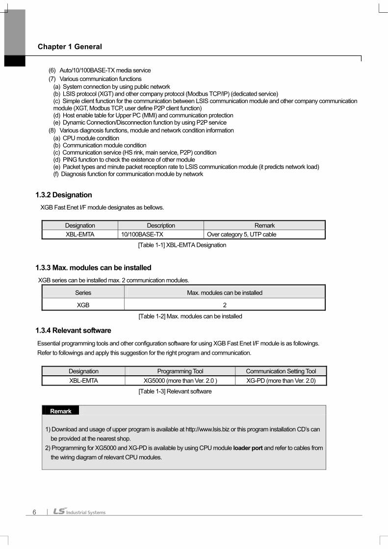
1.3.2 Designation XGB Fast Enet I/F module designates as bellows.
Designation Description Remark XBL-EMTA 10/100BASE-TX Over category 5, UTP cable
[Table 1-1] XBL-EMTA Designation
1.3.3 Max. modules can be installed XGB series can be installed max. 2 communication modules.
Series Max. modules can be installed
XGB 2
[Table 1-2] Max. modules can be installed
1.3.4 Relevant software Essential programming tools and other configuration software for using XGB Fast Enet I/F module is as followings. Refer to followings and apply this suggestion for the right program and communication.
Designation Programming Tool Communication Setting Tool XBL-EMTA XG5000 (more than Ver. 2.0 ) XG-PD (more than Ver. 2.0)
[Table 1-3] Relevant software
Remark
1) Download and usage of upper program is available at http://www.lsis.biz or this program installation CD’s can be provided at the nearest shop.
2) Programming for XG5000 and XG-PD is available by using CPU module loader port and refer to cables from the wiring diagram of relevant CPU modules.

Chapter 2 Specifications
7
Chapter 2 Specifications
2.1 General Specifications
[Table 2-1] shows general specification of XGB series. No. Item Specifications References
1 Operating Temp. 0 +55∼
2 Storage Temp. -25 +70∼
3 Operating Humidity 5 95%RH, ∼ non-condensing.
4 Storage Humidity 5 95%RH, ∼ non-condensing.
Occasional vibration -
Frequency Acceleration Amplitude Sweep count
10 ≤ f < 57Hz − 0.075mm
57 ≤ f ≤ 150Hz 9.8m/s21G −
Continuous vibration
Frequency Acceleration Amplitude
10 ≤ f < 57Hz − 0.035mm
5 Vibrations
57 ≤ f ≤ 150Hz 4.9m/s20.5G −
10 times for
each X, Y, Z
axis
IEC61131-2
6 Shocks
• Maximum shock acceleration : 147 (15g)
• Duration time: 11
• Pulse wave : half sine pulse( 3 shocks per axis, on X,Y,Z axis)
IEC61131-2
Square wave Impulse
noise ±900V
LSIS internal
standard
Electronic discharge Voltage: ±4 (Discharge by contact) IEC61131-2
IEC610004-2
Radiated
electromagnetic field
noise
27~500MHz, 10V/m IEC61131-2
IEC61000-4-3
Item Power supply Digital I/O
Analog I/O
Communication Interface
7 Noise Immunity
Fast transient & Burst
noise
Voltage 2kV 1kV
IEC61131-2
IEC61000-4-4
8 Atmosphere Free of corrosive gases and excessive dust
9 Cooling method Natural air-cooling
10 Altitude Up to 2,000m
11 Pollution degree Less than 2
[Table 2-1] General specification Remark
1) IEC (International Electro-technical Commission): An international civilian institute who establishes international standards in the area of electric and electronics. 2) Pollution degree: An indicator, which indicates pollution degree, which determine insulation performance of equipment. * Pollution degree 2: Normally, only non-conductive pollution occurs. Occasionally, however, a temporary conductively caused by condensation shall be expected.

Chapter 2 Specifications
8
2.2 Transmission Specifications
[Table 2-2] shows transmission specifications of XGB Fast Enet I/F module media. Item Specifications Remark
Transmission speed Auto/10M/100Mbps - Transmission type Base band - Flow control HALF/FULL -
Modulation Type NRZI 4B/5B coding Transformer CT 1:1 Node-Hub Max. distance between nodes 100m - Max. segment length - - Max. number of nodes Hub connection - Nod interval - -
Max. protocol size Data 512bite - Communication zone access method
CSMA/CD -
Transmission
specifications
Check method of frame error CRC32 - [Table 2-2] Transmission specifications
2.3 Cable Specifications
2.3.1 Cable classification
XGB Fast Enet I/F module takes UTP cable which is over Cat 5. [Table 2-3] shows cable specifications.
Classification Details Purpose
UTP(or U.UTP) So called unshielded cable used for HS signal
ㆍ Max. 200MHz ㆍ Phonetic + Data + low grade of video signal
FTP(or S.UTP) Cable with cable core only shielded solely
ㆍ Max.100MHz ㆍ Electronic impediment (EMI) and electric stability considered ㆍ Phonetic + Data + low grade of video signal(
STP(or S.STP) Double-shielded structure, pair shielded and core shielded cable
ㆍ Max. 500MHz ㆍ Phonetic + Data + Video signal ㆍSubstitute for 75Ω coaxial cable
[Table 2-3] Cable class
Remark
1) XGB Fast Enet I/F module does not support AUI (10BASE-5). 2) Twisted paired cable unit (above category 5) takes 100Mbps class hub and if network speed is 10 Mbps, it can be used with 10Mbps class hub (below category 3). Make sure this to install system.
Chapter 2 Specifications
9
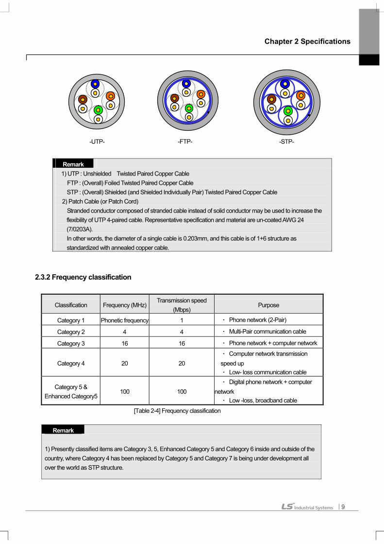
Remark 1) UTP : Unshielded Twisted Paired Copper Cable
FTP : (Overall) Foiled Twisted Paired Copper Cable STP : (Overall) Shielded (and Shielded Individually Pair) Twisted Paired Copper Cable
2) Patch Cable (or Patch Cord) Stranded conductor composed of stranded cable instead of solid conductor may be used to increase the flexibility of UTP 4-paired cable. Representative specification and material are un-coated AWG 24 (7/0203A). In other words, the diameter of a single cable is 0.203mm, and this cable is of 1+6 structure as standardized with annealed copper cable.
2.3.2 Frequency classification
Classification Frequency (MHz) Transmission speed
(Mbps) Purpose
Category 1 Phonetic frequency 1 ㆍ Phone network (2-Pair)
Category 2 4 4 ㆍ Multi-Pair communication cable
Category 3 16 16 ㆍ Phone network + computer network
Category 4 20 20 ㆍ Computer network transmission speed up ㆍ Low- loss communication cable
Category 5 & Enhanced Category5
100 100 ㆍ Digital phone network + computer
network ㆍ Low -loss, broadband cable
[Table 2-4] Frequency classification
Remark 1) Presently classified items are Category 3, 5, Enhanced Category 5 and Category 6 inside and outside of the country, where Category 4 has been replaced by Category 5 and Category 7 is being under development all over the world as STP structure.
-UTP- -STP- -FTP-

Chapter 2 Specifications
10
2.3.3 Category 5 twisted paired cable (UTP) examples (CTP-LAN5)
Item Unit Value
Conductor resistance (Max.) Ω/km 93.5 Insulation resistance (Min.) MΩ·km 2,500
Withstand voltage V/min AC 500 Characteristic impedance Ω(1~100MHz) 100 ± 15
10MHz 6.5 16MHz 8.2 Decrement
Below dB/100m
20MHz 9.3 10MHz 47 16MHz 44 Near-end crosstalk decrement
Below dB/100m
20MHz 42 [Table 2-5] UTP cable specification

Chapter 2 Specifications
11
2.4 Performance Specifications
2.4.1 General performance specifications [Table 2-6] shows general performance specifications of XGB Fast Enet I/F module.
Item Specifications Remark Max. modules can be installed 2 Per 1 CPU unit
Max. numbers of connection channels 6 channels TCP/IP : 4 channels Remote 1: 1 channel Remote 2: 1 channel
Consumption DC 5V 300 -
Weight 71g -
[Table 2-6] General performance specifications
2.4.2 Performance Specifications by Communication Service [Table 2-7] shows performance specifications by communication service of XGB Fast Enet I/F module.
Specifications
Item Driver Communication
method Port Number Remark
TCP/IP 2004 XGT server
UDP/IP 2005 DedicatedMod bus TCP server TCP/IP 502
Max. 4 channels Max. 512 bytes
HS link - UDP/IP 2006 Max. 64 blocks 200 words per block
TCP/IP 2006 XGT client
UDP/IP 2005 Mod bus TCP client TCP/IP 502
TCP/IP User’s
assignment
Function classification
P2P
User define frame UDP/IP
User’s assignment
Max. 3 channels Max. 32 blocks Max. 512 bytes
[Table 2-7] Performance specifications by communication service

Chapter 2 Specifications
12
2.4.3 Diagnosis function specifications [Table 2-8] shows diagnosis function specifications of XGB Fast Enet I/F module.
Item Specifications
Communication module information
HS link station no. IP/Subnet mask IP/Gateway IP/DNS Server IP Main service/HS link/P2P enable Setting media Hardware/ software version
Dedicated service Transmission packet number / Reception packet number / Error
packet number / State Setting drive
HS link Transmission/ Reception packet number HS link flag(Run, Link, Mode, State, TRX, Error)
Service condition
P2P service Connection state / Service state Service count / Error count
Total transmission/Reception packet number Media Information
Packet Rate per sec.
Broad, Multi, Uni, UDP, ARP, EARP, Throw-out
Ping test IP Address / Setting times / Time out
Diagnosis Function
Auto scan Non- service
[Table 2-8] Diagnosis function specification

Chapter 2 Specifications
13
2.5 Dimensions and Names of Parts
2.5.1 Dimensions and names of parts
[Fig. 2-1] Dimensions and names of parts
2.5.2 Designation of Parts
Item Description ① Fixing lever Extension module fixing part (the upper)
On Normal operating RUN Off Stop operating flicker CPU and I/F I/F Off Stop CPU and I/F flicker Data transmission time TX Off Stop data transmitting flicker Data receiving time RX Off No data reception On H/W error
② LED
ERR flicker S/W error flicker Packet reception time
③ LINK LED (Yellow) Off No packet reception
④ RJ45 connector RJ45 connector part
On 100Mbps operating time ⑤ SPEED LED (Green)
Off 10Mbps operating time ⑥ Fixing lever Expansion module fixing part (the lower) ⑦ Fixing lever DIN rail fixing part
[Table 2-9] Designation of Parts
① Fixing lever
② LED part
③ LINK LED
④ RJ45 connector
⑤ SPEED LED
⑥ Fixing lever
⑦ Fixing lever

Chapter 3 Installation
14
Chapter 3 Installation
3.1 Cautions for Installation
This device has high reliability regardless of its installation environment. But the followings should be noted for securing reliability and stability.
3.1.1 Environmental conditions (1) Install on a water-proof and dust control panel (2) Place free of continuous impact or vibration (3) Place out of direct sunrays (4) Place without dewing by sudden temperature change (5) Place where ambient temperature is between 0-55.
3.1.2 Installation cautions (1) If producing screw holes or wiring, it should be noted that any impurities from wiring work are not to be inserted into PLC. (2) Install on an accessible place. (3) Do not install on high voltage device or same panel. (4) Continuous it 50mm and wider out of duct or surrounding modules. (5) Ground on a place where little noise is detected
3.1.3 Handling cautions (1) Do not drop or do not apply any excessive impact on it. (2) Do not separate PCB from case(shield), which may cause breakage. (3) Make sure that while wiring, any impurities should not be inserted into the upper part of this module. (4) Do not attach or detach the module once power is on. (5) Cable should be selected considering the approved specification, install this device within the permitted
max. distance. (6) AC and external I/O signal of positioning module are not subject to any surge or induced noise generated from AC. (7) If wiring is too close to any hot devices or materials or contacts with oils for a long time, it may cause short circuit,
malfunction or destruction. (8) If wiring by using pipes, it needs grounding pipes.

Chapter 3 Installation
15
3.2 Installation and Wiring
3.2.1 Network connection
[Fig. 3-1] Network connection
3.2.2 UTP cable wiring
Max. distance between nodes of 10/100BASE-TX is 100m(module - Hub). The hub is in general use straight cable with TD and RD stranded inside. If only 2 of these communication modules are connected 1 to 1, cross-cable form may be used.
Pin no. Signal Straight cable (module-Hub) 1 to 1 cross-cable
1 2 3 6
4, 5, 7, 8
TD+ TD- RD+ RD- N/A
1 — 1 2 — 2 3 — 3 6 — 6
1 — 3 2 — 6 3 — 1 6 — 2
[Table 3-1] Cable wiring
Remark
1) Hub power should be separated from PLC power. 2) Contact professional manufacturers for processing cable terminal, manufacture and installation.
8 pin RJ-45 plug
Twisted paired cable
Hub
네트워크 (Network)
Network

Chapter 3 Installation
16
(1) Cautions for UTP installation
(a) UTP cable should be satisfied the characteristics of category 5. (b) Do not access Max. tension strength of the cable during a period of wiring processing. (c) Do remove only the length of wiring, do not damage the insulator for removing covering (Sheath). (d) Keep suitable distance between EMI source and UTP cable during the period of installing UTP cable.
Min. separation distance Condition
2.0KVA or less 2.5 KVA 5.0KVA or morePower line unshielded, or electric facility open or near to nonmetallic pipe
127mm 305mm 610mm
Power line unshielded, or electric facility near to metallic pipe buried
64mm 152mm 305mm
Power line inside metallic pipe buried (or equivalently shielded) near to metallic pipe buried
- 76mm 152mm
Transformer / Electric motor light 1,016mm /305mm [Table 3-2] Cautions for UTP installation
3.2.3 Cautions for system and network connection (1) IP address should be different including this module. If not, normal communication is not available. (2) Set each exchange number differently for using HS link service. (3) Use specified communication cable. Other cables may occur communication trouble. (4) Check disconnection or short circuit of communication cable before installation. (5) Do tighten communication cable connector. (6) If cable connection is not stable, it may occur some severe trouble of communication. (7) Do wiring processing of communication cable separately from power supply line or inductive noise.

Chapter 3 Installation
17
3.2.4 Check points before start-up
The following describes check points before start-up communication module.
(1) Communication module Check points
Installation and operation of XG5000, Performance and operation of XG-PD
Connection condition of communication cable (only the condition of connecting cable)
Module installation condition [Table 3-3] Check points before start-up
(2) Start-up processing It shows start -up from finishing installation of module on PLC.
Start Power- ON : 1) Check power source 2) Check the connection of communication cable 3) Power- ON. 4) Check LED ‘ON’ of power supply 5) Check LED status on CPU module -> If abnormal, refer to the troubleshooting contents of each PLC manual. 6) Check LED status (normal/abnormal) of communication module -> If abnormal, refer to chapter 10. Troubleshooting of this manual. 7) Download after setting system parameter correctly
Programming : Program at XG5000, Write on CPU module
Sequence check : Check module operation by program
Program correction : Do correct if sequence program has problem
Saving program: 1) Save program in floppy disc or hard disc. 2) Print out circuit diagram and list by printer.
End

Chapter 4 System Configuration
18
Chapter 4 System Configuration
4.1 General
4.1.1 General XGB Fast Enet I/F module supports open Enet. It provides network configuration that is to connect LSIS and other company PLC, PC
on network.
4.2 Examples of System Configuration
4.2.1 Combination network configuration
[Figure 4-1] Combination network configuration XGB Fast Enet I/F module provides system configuration by using main communication, Modbus TCP/IP, user define frame, HS link communication connecting LSIS PLC with other LSIS PLC, PC on network.
4.2.2 Network configuration using XGB
[Figure 4-2] Network configuration using XGB
Communication between XGB Fast Enet I/F modules is available to perform 1:1 communication by using cross cable or 1:N communication by connecting network. It provides data sending/receiving by using the dedicated service, Modbus TCP/IP, user define frame and HS link communication.

Chapter 4 System Configuration
19
4.2.3 Network configuration using XGB and MMI
[Figure 4-3] Network configuration using XGB and MMI
Communication between XGB Fast Enet I/F module and PC is available to perform 1:1 communication by using cross cable or 1:N communication by connecting network. It provides connecting and data sending/receiving by using XG5000, XG-PD or MMI on PC. XG5000, XG-PD do download/upload parameter and program and furthermore these provide data sending/receiving by using the dedicated service, Modbus TCP/IP, user define frame.
4.2.4 Network configuration between LSIS modules
[Figure 4-4] Network configuration between LSIS modules
XGB Fast Enet I/F module and Enet I/F of XGT series provide system configuration. 1:1 communication is available using cross cable or 1:N communication is available by connecting network. It provides data sending/receiving by using main service, Modbus TCP/IP, user define frame.
4.2.5 Network configuration using XGB and other LSIS PLC
[Figure 4-5] Network configuration using XGB and other LSIS PLC
XGB Fast Enet I/F module provides communication with other LSIS PLC, HMI, MMI. . 1:1 communication is available using cross cable or 1:N communication is available by connecting network. To communicate, protocols between PLCs should be same.

Chapter 5 Protocols of Various Services
20
Chapter 5 Protocols of Various Services
5.1 General
5.1.1 XGB Fast Enet I/F module protocol introduction XGB Fast Enet I/F module supports open Ethernet. It provides network configuration that is to connect LSIS and other company PLC, PC on network. To set IP, parameter of each PLC, protocol should be followed to do communicate after finishing network configuration. Supported protocols by XGB Fast Enet I/F module are XGT dedicated, Modbus TCP/IP, user define frame. Each protocol supports server/client operation. Dedicated server and P2P function communicate according to the designated protocols.
5.1.2 Protocol by service Each protocol’s classified server/client by its function. [Table 5-1] shows protocol by service.
Specification
Item Driver
Communication method
Port No. Remark
TCP/IP 2004 XGT server
UDP/IP 2005 Dedicated
Modbus TCP server TCP/IP 502
Max. 4 channels
Max. 512 bytes
TCP/IP 2004 XGT client
UDP/IP 2005
Modbus TCP client TCP/IP 502 TCP/IP User’s assignment
Communication function
P2P
User define frame UDP/IP User’s assignment
Max. 3 channels Max. 32 blocks
[Table 5-1] Protocols of various services

Chapter 5 Protocols of Various Services
21
5.2 XGT Dedicated Protocol
5.2.1 General XGT main protocol does communicate between LSIS Enet I/F modules. Read/write is available by instructions and
communication is available on PC, HMI by using XGT dedicated protocol.
XGT dedicated communication is available in 2-ways communication method of TCP and UDP.
Protocol Communication method Port no.
TCP/IP 2004 XGT dedicated
UDP/IP 2005 [Table 5-2] XGT main protocol
5.2.2 Frame structure (1) XGT dedicated packet structure through Enet During the period of communicating by using XGT dedicated protocol, it includes LSIS frame which includes MAC, IP header, TCP header and data for Enet communication. [Fig. 5-1] shows XGT dedicated packet structure through Enet.
IP HeaderMAC TCP Header LS IS Frame Format
TCP/IP Data Frame
Ethernet Request / Response Frame
[Figure 5-1] XGT dedicated packet structure through Ethernet
(2) XGT dedicated frame structure LSIS own frame for data communication includes LSIS ID, instruction, data type, data. [Fig.5-2] shows XGT dedicated frame structure.
LS IS Frame Format
Company Header Commnad Data Type Data
[Figure 5-2] XGT dedicated frame structure

Chapter 5 Protocols of Various Services
22
5.2.3 XGT dedicated protocol data type
XGT dedicated protocol is available to take [Table. 5-3] data type. Data type Data code Example
Bit 0x0000 %PX0,%LX0,%FX0 Byte 0x0100 %MB0, %PB0, %DB0 Word 0x0200 %PW0,%LW0,%FW0,%DW0
DWord 0x0300 %PD0,%LD0,%FD0,%DD0
LWord 0x0400 %PL0,%LL0,%FL0,%DL0
Continuous(Byte) 0x1400 - [Table 5-3] XGT dedicated protocol data type
5.2.4 Instruction of XGT dedicated protocol Using instructions of XGT dedicated protocol are 4 , each instruction does Read/Write, Request/Response. In case of ‘Individual’, usable data types of each instruction are Bit, Byte, Word, DWord, LWord. But for the ‘Continuous’, only Byte is usable. Instruction Instruction code Data type Treatment
0x0000 0x0100 0x0200 0x0300
Individual
0x0400
Reads data by each data type Request : 0x5400
Continuous 0x1400 Reads byte type variables in block unit
0x0000 0x0100 0x0200 0x0300
Individual
0x0400
Responses to the request of Read data
Read
Response : 0x5500
Continuous 0x1400 Response to the request of Read in block unit
0x0000 0x0100 0x0200 0x0300
Individual
0x0400
Writes by each data type Request : 0x5800
Continuous 0x1400 Read byte type variables in block unit
0x0000 0x0100 0x0200 0x0300
Individual
0x0400
Responses to the request of Write data
Write
Response: 0x5900
Continuous 0x1400 Responses to the request of Write in block unit
[Table 5-4] Instruction of XGT dedicated protocol
Chapter 5 Protocols of Various Services
23
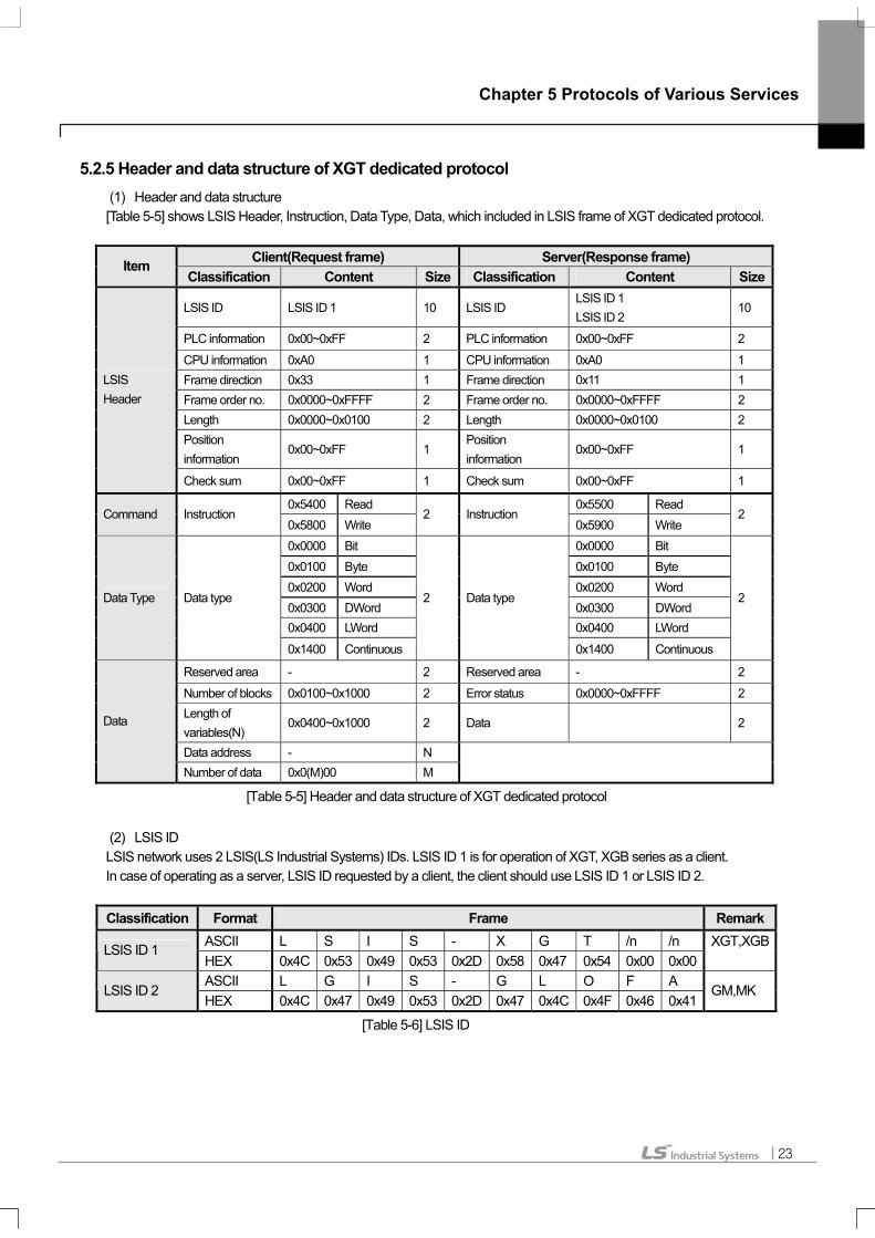
5.2.5 Header and data structure of XGT dedicated protocol (1) Header and data structure
[Table 5-5] shows LSIS Header, Instruction, Data Type, Data, which included in LSIS frame of XGT dedicated protocol.
Client(Request frame) Server(Response frame) Item Classification Content Size Classification Content Size
LSIS ID LSIS ID 1 10 LSIS ID LSIS ID 1 LSIS ID 2
10
PLC information 0x00~0xFF 2 PLC information 0x00~0xFF 2
CPU information 0xA0 1 CPU information 0xA0 1 Frame direction 0x33 1 Frame direction 0x11 1 Frame order no. 0x0000~0xFFFF 2 Frame order no. 0x0000~0xFFFF 2 Length 0x0000~0x0100 2 Length 0x0000~0x0100 2 Position information
0x00~0xFF 1 Position information
0x00~0xFF 1
LSIS Header
Check sum 0x00~0xFF 1 Check sum 0x00~0xFF 1
0x5400 Read 0x5500 Read Command Instruction
0x5800 Write 2 Instruction
0x5900 Write 2
0x0000 Bit 0x0000 Bit 0x0100 Byte 0x0100 Byte 0x0200 Word 0x0200 Word 0x0300 DWord 0x0300 DWord 0x0400 LWord 0x0400 LWord
Data Type Data type
0x1400 Continuous
2 Data type
0x1400 Continuous
2
Reserved area - 2 Reserved area - 2
Number of blocks 0x0100~0x1000 2 Error status 0x0000~0xFFFF 2 Length of variables(N)
0x0400~0x1000 2 Data 2
Data address - N
Data
Number of data 0x0(M)00 M
[Table 5-5] Header and data structure of XGT dedicated protocol
(2) LSIS ID LSIS network uses 2 LSIS(LS Industrial Systems) IDs. LSIS ID 1 is for operation of XGT, XGB series as a client. In case of operating as a server, LSIS ID requested by a client, the client should use LSIS ID 1 or LSIS ID 2. Classification Format Frame Remark
ASCII L S I S - X G T /n /n LSIS ID 1 HEX 0x4C 0x53 0x49 0x53 0x2D 0x58 0x47 0x54 0x00 0x00
XGT,XGB
ASCII L G I S - G L O F A LSIS ID 2
HEX 0x4C 0x47 0x49 0x53 0x2D 0x47 0x4C 0x4F 0x46 0x41 GM,MK
[Table 5-6] LSIS ID

Chapter 5 Protocols of Various Services
24
5.2.6 Frame examples (1) Request frame for individual reading of variables
[Table 5-7] Request frame for individual reading of variables
(2) Response frame for individual reading of variables
[Table 5-8] Response frame for individual reading of variables
Chapter 5 Protocols of Various Services
25
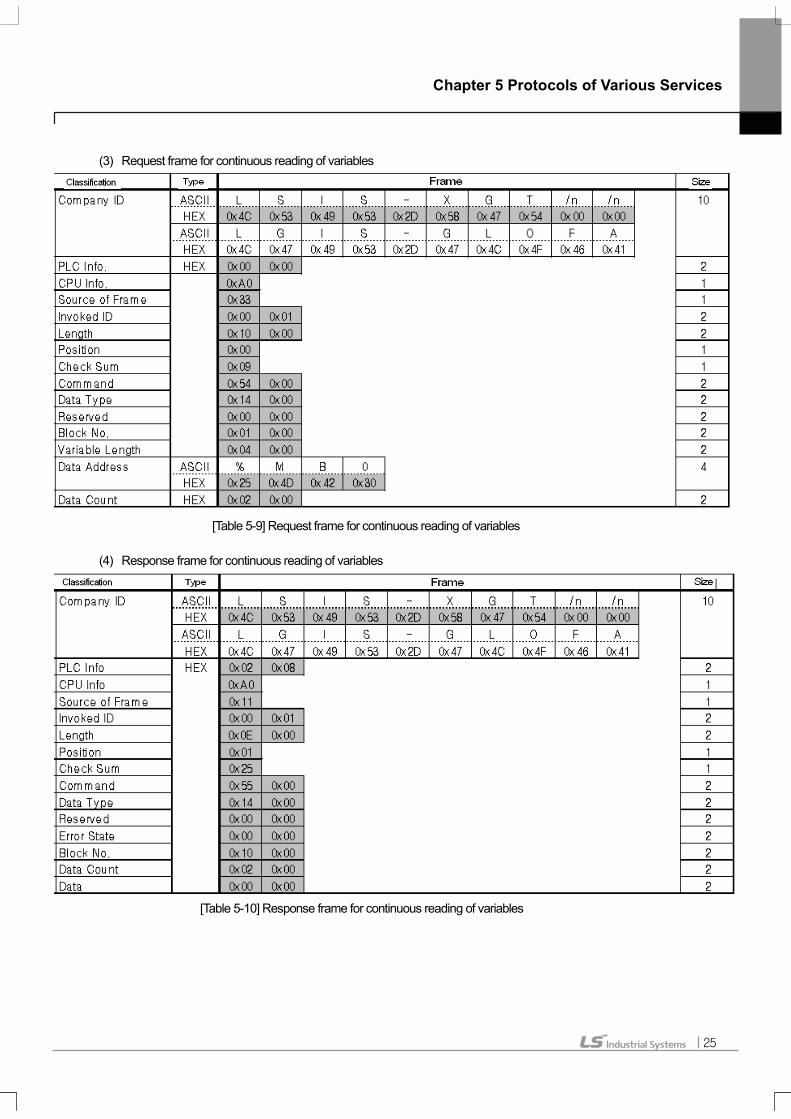
(3) Request frame for continuous reading of variables
[Table 5-9] Request frame for continuous reading of variables
(4) Response frame for continuous reading of variables
[Table 5-10] Response frame for continuous reading of variables

Chapter 5 Protocols of Various Services
26
5.3 Modbus TCP/IP Protocol
5.3.1 General Modbus TCP/IP protocol function is to data Read/Write by using function codes. Modbus TCP/IP frame is composed of MAC, IP
Header, TCP Header, Modbus ADU for Enet communication.
(1) ADU : Application Data Unit (2) MBAP : MODBUS Application Protocol (3) PDU : Protocol Data Unit
5.3.2 Structure of Modbus TCP/IP frame (1) Structure of Modbus TCP/IP frame through Enet
IP HeaderMAC TCP Header MODBUS TCP/IP ADU
MODBUS TCP/IP ADU
Ethernet Request / Response Frame
[Figure 5-3] Structure of Modbus TCP/IP frame through Enet
MABP Header
Transaction Identifier Protocol Identifier Length Unit Identifier
[Figure 5-4] Structure of Modbus TCP/IP ADU
MABP Header Function Code Data
MODBUS TCP/IP ADU
PDU [Figure 5-5] Structure of Modbus ADU
Chapter 5 Protocols of Various Services
27
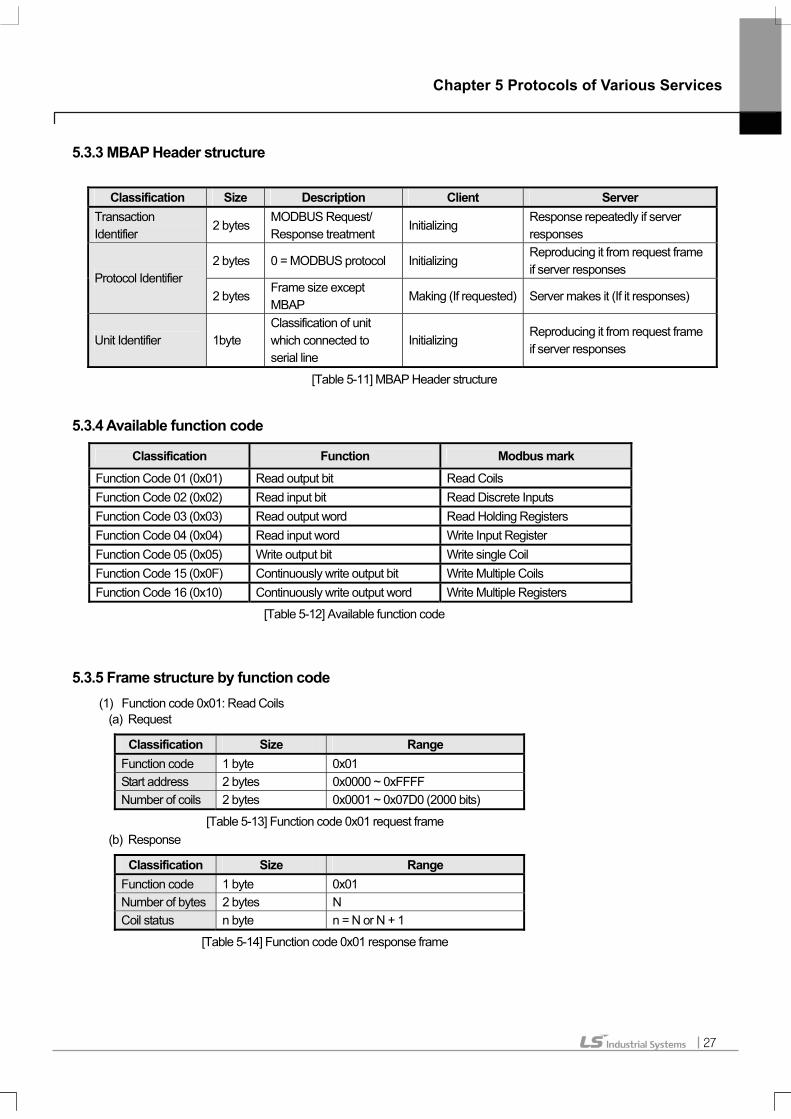
5.3.3 MBAP Header structure
Classification Size Description Client Server Transaction Identifier
2 bytes MODBUS Request/ Response treatment
Initializing Response repeatedly if server responses
2 bytes 0 = MODBUS protocol Initializing Reproducing it from request frame if server responses
Protocol Identifier 2 bytes
Frame size except MBAP
Making (If requested) Server makes it (If it responses)
Unit Identifier 1byte Classification of unit which connected to serial line
Initializing Reproducing it from request frame if server responses
[Table 5-11] MBAP Header structure
5.3.4 Available function code
Classification Function Modbus mark
Function Code 01 (0x01) Read output bit Read Coils Function Code 02 (0x02) Read input bit Read Discrete Inputs Function Code 03 (0x03) Read output word Read Holding Registers Function Code 04 (0x04) Read input word Write Input Register Function Code 05 (0x05) Write output bit Write single Coil Function Code 15 (0x0F) Continuously write output bit Write Multiple Coils Function Code 16 (0x10) Continuously write output word Write Multiple Registers
[Table 5-12] Available function code
5.3.5 Frame structure by function code (1) Function code 0x01: Read Coils
(a) Request
Classification Size Range Function code 1 byte 0x01 Start address 2 bytes 0x0000 ~ 0xFFFF Number of coils 2 bytes 0x0001 ~ 0x07D0 (2000 bits)
[Table 5-13] Function code 0x01 request frame (b) Response
Classification Size Range Function code 1 byte 0x01 Number of bytes 2 bytes N Coil status n byte n = N or N + 1
[Table 5-14] Function code 0x01 response frame
Chapter 5 Protocols of Various Services
28
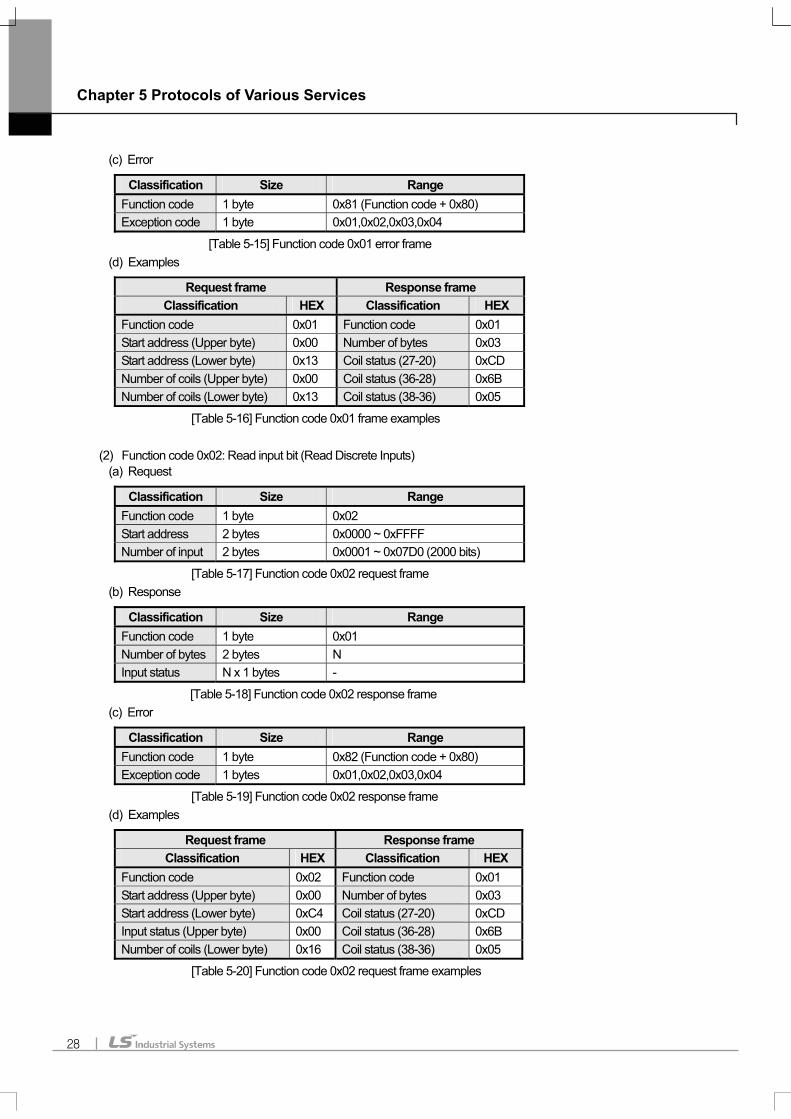
(c) Error
Classification Size Range Function code 1 byte 0x81 (Function code + 0x80) Exception code 1 byte 0x01,0x02,0x03,0x04
[Table 5-15] Function code 0x01 error frame (d) Examples
Request frame Response frame Classification HEX Classification HEX
Function code 0x01 Function code 0x01 Start address (Upper byte) 0x00 Number of bytes 0x03 Start address (Lower byte) 0x13 Coil status (27-20) 0xCD Number of coils (Upper byte) 0x00 Coil status (36-28) 0x6B Number of coils (Lower byte) 0x13 Coil status (38-36) 0x05
[Table 5-16] Function code 0x01 frame examples
(2) Function code 0x02: Read input bit (Read Discrete Inputs) (a) Request
Classification Size Range Function code 1 byte 0x02 Start address 2 bytes 0x0000 ~ 0xFFFF Number of input 2 bytes 0x0001 ~ 0x07D0 (2000 bits)
[Table 5-17] Function code 0x02 request frame (b) Response
Classification Size Range Function code 1 byte 0x01 Number of bytes 2 bytes N Input status N x 1 bytes -
[Table 5-18] Function code 0x02 response frame (c) Error
Classification Size Range Function code 1 byte 0x82 (Function code + 0x80) Exception code 1 bytes 0x01,0x02,0x03,0x04
[Table 5-19] Function code 0x02 response frame (d) Examples
Request frame Response frame Classification HEX Classification HEX
Function code 0x02 Function code 0x01 Start address (Upper byte) 0x00 Number of bytes 0x03 Start address (Lower byte) 0xC4 Coil status (27-20) 0xCD Input status (Upper byte) 0x00 Coil status (36-28) 0x6B Number of coils (Lower byte) 0x16 Coil status (38-36) 0x05
[Table 5-20] Function code 0x02 request frame examples

Chapter 5 Protocols of Various Services
29
(3) Function code 0x03: Read Holding Registers (a) Request
Classification Size Range Function code 1 byte 0x03 Start address 2 bytes 0x0000 ~ 0xFFFF Number of input 2 bytes 0x0001 ~ 0x007D (125 words)
[Table 5-21] Function code 0x03 request frame (b) Response
Classification Size Range Function code 1 byte 0x01 Number of bytes 2 bytes 2 x N Input status N x 2 bytes -
[Table 5-22] Function code 0x03 response frame (c) Error
Classification Size Range Function code 1 byte 0x83 (Function code + 0x80) Exception code 1 byte 0x01,0x02,0x03,0x04
[Table 5-23] Function code 0x03 error frame (d) Examples
Request frame Response frame Classification HEX Classification HEX
Function code 0x03 Function code 0x03 Start address (Upper byte) 0x00 Number of bytes 0x06 Start address (Lower byte) 0x6B Word status (108) 0x02 Number of words (Upper byte) 0x00 Word status (108) 0x2B Number of words (Lower byte) 0x03 Word status (109) 0x00
Word status (109) 0x00 Word status (110) 0x00 Word status (110) 0x64
[Table 5-24] Function code 0x03 frame examples
(4) Function code 0x04: Read Input Registers (a) Request
Classification Size Range Function code 1 byte 0x04 Start address 2 bytes 0x0000 ~ 0xFFFF Number of input 2 bytes 0x0001 ~ 0x007D (125 words)
[Table 5-25] Function code 0x04 request frame (b) Response
Classification Size Range Function code 1 byte 0x04 Number of byte 2 bytes 2 x N Input status N x 2 bytes -
[Table 5-26] Function code 0x04 response frame

Chapter 5 Protocols of Various Services
30
(c) Error
Classification Size Range Function code 1 byte 0x84 (Function code + 0x80) Exception code 1 byte 0x01,0x02,0x03,0x04
[Table 5-27] Function code 0x04 error frame (d) Examples
Request frame Response frame Classification HEX Classification HEX
Function code 0x04 Function code 0x04 Start address (Upper byte) 0x00 Number of bytes 0x02 Start address (Lower byte) 0x08 Word status (108) 0x00 Number of words (Upper byte) 0x00 Word status (108) 0x0A Number of words (Lower byte) 0x01
[Table 5-28] Function code 0x04 frame examples
(5) Function code 0x05: Write Single Coil (a) Request
Classification Size Range Function code 1 byte 0x05 Start address 2 bytes 0x0000 ~ 0xFFFF Input value 2 bytes 0x0000 or 0xFF0D
[Table 5-29] Function code 0x05 request frame (b) Response
Classification Size Range Function code 1 byte 0x05 Number of bytes 2 bytes 0x0000 ~ 0xFFFF Input status 2 bytes 0x0000 or 0xFF00
[Table 5-30] Function code 0x05 response frame (c) Error
Classification Size Range Function code 1 byte 0x85 (Function code + 0x80) Exception code 1 byte 0x01,0x02,0x03,0x04
[Table 5-31] Function code 0x05 error frame (d) Examples
Request frame Response frame Classification HEX Classification HEX
Function code 0x02 Function code 0x01 Start address (Upper byte) 0x00 Number of bytes 0x03 Start address (Lower byte) 0xC4 Coil status (27-20) 0xCD Input status (Upper byte) 0x00 Coil status (36-28) 0x6B Number of coils (Lower byte) 0x16 Coil status (38-36) 0x05
[Table 5-32] Function code 0x05 frame examples

Chapter 5 Protocols of Various Services
31
(6) Function code 0x0F: Write Multiple Registers (a) Request
Classification Size Range Function code 1 byte 0x0F Start address 2 bytes 0x0000 ~ 0xFFFF Number of output
2 bytes 0x0001 ~ 0x07BD
Number of bytes 1 byte N Output value N x 1 byte
[Table 5-33] Function code 0x0F request frame (b) Response
Classification Size Range Function code 1 byte 0x0F Number of bytes 2 bytes 0x0000 ~ 0xFFFF Input status 2 bytes 0x0001 ~ 0x07B0
[Table 5-34] Function code 0x0F response frame (c) Error
Classification Size Range Function code 1 byte 0x8F (Function code + 0x80) Exception code 1 byte 0x01,0x02,0x03,0x04
[Table 5-35] Function code 0x0F request frame (d) Examples
Request frame Response frame Classification HEX Classification HEX
Function code 0x0F Function code 0x0F Start address (Upper byte) 0x00 Start address (Upper byte) 0x00 Start address (Lower byte) 0x13 Start address (Lower byte) 0x13 Number of output (Upper byte) 0x00 Number of output(Upper byte) 0x00 Number of output (Lower byte) 0x0A Number of output(Lower byte) 0x0A Number of bytes 0x02 Output value (Upper byte) 0xCDOutput value (Lower byte) 0x01
[Table 5-36] Function code 0x01 request frame examples
(7) Function code 0x06: Write Single Register (a) Request
Classification Size Range Function code 1 byte 0x06 Start address 2 bytes 0x0000 ~ 0xFFFF Output value 2 bytes 0x0000 or 0xFFFF
[Table 5-37] Function code 0x06 request frame

Chapter 5 Protocols of Various Services
32
(b) Response
Classification Size Range Function code 1 byte 0x06 Start address 2 bytes 0x0000 ~ 0xFFFF Output value 2 bytes 0x0000 or 0xFFFF
[Table 5-38] Function code 0x06 response frame (c) Error
Classification Size Range Function code 1 byte 0x86 (Function code + 0x80) Exception code 1 byte 0x01,0x02,0x03,0x04
[Table 5-39] Function code 0x06 error frame (d) Examples
Request frame Response frame Classification HEX Classification HEX
Function code 0x06 Function code 0x06Start address (Upper byte) 0x00 Number of bytes 0x00Start address (Lower byte) 0x01 Coil status (27-20) 0x01Input status (Upper byte) 0x00 Coil status (36-28) 0x00Number of coils(Lower byte) 0x03 Coil status (38-36) 0x03
[Table 5-40] Function code 0x06 frame examples
(8) Function code 0x10: Write Multiple Registers (a) Request
Classification Size Range Function code 1 byte 0x10 Start address 2 bytes 0x0000 ~ 0xFFFF Number of output 2 bytes 0x0001 or 0x07D8 Number of bytes 1 byte 2 x N Output value N x 2 bytes value
[Table 5-41] Function code 0x10 request frame (b) Response
Classification Size Range Function code 1 byte 0x10 Number of bytes 2 bytes 0x0000 ~ 0xFFFF Number of output
2 bytes 0x0001 ~ 0x007B
[Table 5-42] Function code 0x01 response frame (c) Error
Classification Size Range Function code 1 byte 0x90 (Function code + 0x80) Exception code 1 byte 0x01,0x02,0x03,0x04
[Table 5-43] Function code 0x10 error frame

Chapter 5 Protocols of Various Services
33
(d) Examples
Request frame Response frame Classification HEX Classification HEX
Function code 0x10 Function code 0x01Start address (Upper byte) 0x00 Start address (Upper byte) 0x00Start address (Lower byte) 0x01 Start address (Lower byte) 0x01Number of output (Upper byte) 0x00 Number of output (Upper byte) 0x00Number of output (Lower byte) 0x02 Number of output (Lower byte) 0x02Number of bytes 0x04 Output value (Upper byte) 0x00 Output value (Lower byte) 0x0A Output value (Upper byte) 0x01 Output value (Lower byte) 0x02
[Table 5-44] Function code 0x10 frame examples
Chapter6 Dedicated Service
34
Chapter 6 Dedicated Service
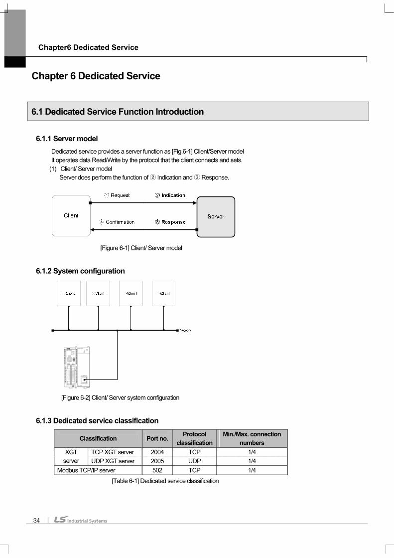
6.1 Dedicated Service Function Introduction
6.1.1 Server model Dedicated service provides a server function as [Fig.6-1] Client/Server model It operates data Read/Write by the protocol that the client connects and sets.
(1) Client/ Server model Server does perform the function of ② Indication and ③ Response.
[Figure 6-1] Client/ Server model
6.1.2 System configuration
[Figure 6-2] Client/ Server system configuration
6.1.3 Dedicated service classification
Classification Port no. Protocol classification
Min./Max. connection numbers
TCP XGT server 2004 TCP 1/4 XGT server UDP XGT server 2005 UDP 1/4
Modbus TCP/IP server 502 TCP 1/4
[Table 6-1] Dedicated service classification

Chapter 6 Dedicated Service
35
6.2 Setting Dedicated Service
6.2.1 Basic parameter (1) Setting basic parameter in XG-PD Open XG-PD. Then, select slot that installed XBL-EMTA on project window. Double-click the slot.
[Figure 6-3] Selecting basic parameter and setting communication module Double-clicking shows ‘communication module setting window’. Select FEnet from communication modules, then click enter key. Finally, it shows the window as below [Fig. 6-4] Setting FEnet .
[Figure 6-4] Setting basic parameter Double-clicking FEnet shows the basic setting window as below [Fig.6-5].
Double-click
Select FEnet
Double-click

Chapter6 Dedicated Service
36
(2) Basic setting (a) Receiving stand-by time is by the time of disconnection without the client’s request. (b) Number of dedicated connection is the number of connecting clients. Up to 4 is available. (c) Number of channels of P2P is 4-dedicated connection numbers. (d) Setting driver (server) can be done by XGT server or Modbus TCP/IP (e) Server operates by the setting driver protocol. (f) Setting host table assign client IP. (g) Setting check box of enable host table makes connection only to registered IP.

Chapter 6 Dedicated Service
37
6.3 XGT Server
6.3.1 TCP XGT server TCP XGT server operates as below [Fig.6-5] TCP XGT server operation flow.
Client
Time
①SYN
Time
②SYN ACK
③ACK
④PUSH ACK
PUSH ACK
⑥ACK
⑦FIN ACK
⑧ACK
⑨RST
Server
Transmission port : n >1024Destination port : 2004
Connection
Disconnection
Connection
Disconnection
XGT dedicated protocol(Client)
XGT dedicated protocol(Server)
Transmission port : n >1024Destination port : 2004
[Figure 6-5] TCP XGT server operation flow
(1) Connection (a) Client does transmit ① SYN to serve. Server does ② SYN ACK. (b) Connection port no. is XGT dedicated protocol port no. 2004. (c) Client does connection check response ③ ACK. (d) Finishing ~① ③ makes client/server connection.
(2) TCP XGT server (a) After connection, client does transmit PUSH ACK according to XGT dedicated protocol.④ (b) Server does transmit ⑤ PUSH ACK for PUSH ACK Frame. (c) Client does transmit ⑥ACK.
(3) Disconnection (a) Client does transmit ⑦ DISCONNECTION. (b) Server does transmit ⑧ RST and disconnect.

Chapter6 Dedicated Service
38
6.4 Modbus TCP/IP Server Modbus TCP/IP server operates as below [Fig.6-6] Modbus TCP/IP Server operation flow.
Client
Time
①SYN
Time
②SYN ACK
③ACK
④PUSH ACK
PUSH ACK
⑥ACK
⑦FIN ACK
⑧ACK
⑨RST
Server
Transmission port : n >1024Destination port: 502
Connection
Disconnection
Connection
Disconnection
Modbus TCP/IP protocol(Client)
Modbus TCP/IP protocol(Server)
Transmission port : n >1024Destination port: 502
[Figure 6-6] Modbus TCP/IP Server operation flow
(4) Connection (a) Client does transmit SYN① to serve. Server does SYN ACK.② (b) Connection port no. is XGT dedicated protocol port no. 502. (c) Client does connection check response ACK.③ (d) Finishing ~ makes client/server connection.① ③
(5) TCP XGT client (a) After connection, client does transmit PUSH ACK ac④ cording to XGT dedicated protocol. (b) Server does transmit PUSH ACK for PUSH ACK Frame. ⑤ (c) Client does transmit ACK.⑥
(6) Disconnection (a) Client does transmit DISCONNECTION.⑦ (b) Server does transmit RST and disconnect. ⑧

Chapter 7 P2P Service
39
Chapter 7 P2P Service
7.1 P2P Service Function Introduction
7.1.1 Client model P2P service provides a client function as below [Fig.7-1] Client/Server model. It requests data Read/Write to server. When each block operation status is ON, it provides the function of connecting request frame to the right channel and receiving response. XGB Fast Enet I/F module communicates through Max.3 channels, each channel communicates by using different protocols.
[Fig. 7-1] Client/Server model Server executes ① Request and ④ Confirmation.
[Fig. 7-2] Client/Server system configuration
XBL-EMTA is available to connect Max. 3 servers as [Fig 7-2].

Chapter 7 P2P Service
40
7.2 Setting P2P Service
7.2.1 Setting P2P parameter (1) Setting communication module
[Fig. 7-3] Communication module setting screen in P2Pparameter
(a) As the left part of [Fig.7-3] project screen, select P2P02 or P2P03, double-click it. (b) P2P01 is a setting value of XGB CPU internal communication. It’s fixed as Cnet. (c) Double-clicking shows communication setting screen as the right part of [Fig.7-3]. (d) Set FEnet in types. (e) Base is fixed as 00. (f) Slot is 01~07. Set it by the installation sequence of XBL-EMTA. (g) After finishing setting communication module, click enter key. (h) Clicking enter key shows detailed item of P2P as [Fig.7-4].
[Fig. 7-4] Finishing setting communication module in P2P parameter

Chapter 7 P2P Service
41
(2) Setting channel
[Fig. 7-5] P2P channel setting screen
(a) As the left screen of [Fig.7-5] project screen, select P2P channel, double-click it. (b) Double-clicking shows P2P channel setting screen as the right part of [Fig. 7-5]. (c) Select the desired driver by clicking the arrow icon of P2P driver on P2P channel setting screen. (d) Select driver
(3) XGT client (a) In case of assigning XGT client, TCP/UDP should be selected. (b) Selecting TCP assigns port no. 2004. Selecting UDP assigns port no.2005. (c) Write the destination IP address.
(4) Modbus TCP client (a) Selecting Modbus client fixes port no.502. (b) Write the destination IP address.
(5) User define frame (a) In case of assigning user define frame, communication type should be selected as TCP/UDP. (b) Select Client/Server in operation mode. (c) Write the desired port no. (d) Write the destination IP address.
[Fig.7-6] is an example that setting P2P on 3 channels.
[Fig. 7-6] Example of setting P2P

Chapter 7 P2P Service
42
(6) Setting P2P block
[Fig. 7-7] P2P block setting screen
(a) After finishing setting channels, select P2P block on the project screen as the left screen of [Fig.7-7], double-click it. (b) Double-clicking shows block setting screen as the right screen of [Fig.7-7].
(7) Setting P2P block channel
[Fig. 7-8] Setting P2P block channel
(a) Assign each block channel as the left screen of [Fig. 7-8]. Select one from registered channels (0~3). (b) Assigning the desired channel as the right screen of [Fig. 7-8] saves assigned driver on setting channel.

Chapter 7 P2P Service
43
(8) Setting P2P block driver
[Fig. 7-9] Setting P2P block function and operation condition
(a) Select P2P function as the left screen of [Fig. 7-9]. Function can be selected by the assigned channel driver. (b) Client selects READ/WRITE. (c) Modbus TCP client selects READ/WRITE. (d) User define frame selects SEND/RECEIVE. (e) Write operation condition as the right screen of [Fig. 7-9]. Operation condition is an internal device of XGB CPU
(9) Setting P2P block type
[Fig 7-10] Setting P2P block type and data type
(a) Select the type as the left screen of [Fig. 7-10]. Function can be selected by the assigned channel driver. (b) XGT client selects SINGLE/CONTINOUS. (c) Modbus TCP client selects SINGLE/CONTINOUS. (d) User define frame can not select types. (e) Write operation condition as the left screen of [Fig. 7-10]. Operation condition is an internal device of XGB CPU

Chapter 7 P2P Service
44
(10) Setting number of P2P block variables
[Fig. 7-11] Setting number of P2P block variables
(a) Set number of variables as [Fig. 7-11]. (b) XGT client selects SINGLE/CONTINUOUS. (c) Modbus TCP client is fixed as 1. (d) User define frame can not select types.
(11) Setting P2P block variables
[Fig. 7-12] Setting P2P block variables
(a) Select the variable as the left screen of [Fig. 7-12]. Double-click it. (b) Double-clicking shows the screen of setting variables as the right screen of [Fig. 7-12]. (c) Write can be 1~4 variables by the setting numbers of variables.

Chapter 7 P2P Service
45
[Fig. 7-13] Finishing setting P2P block variables and setting block
(d) Write read area/save area of XGB CPU as the left screen of [Fig. 7-13]. (e) Clicking enter key finishes setting block as [Fig. 8-11].
7.2.2 Enable link (1) P2P enable setting screen
[Fig. 7-14] P2P enable setting screen
(a) After setting P2P function, P2P enable should be set to start P2P service. (b) Connect XG-PD as the left screen of [Fig. 7-14], Select enable link on Online menu. (c) It shows enable link screen as the right screen of [Fig. 7-14].

Chapter 7 P2P Service
46
(2) P2P enable
[Fig. 7-15] P2P enable
(a) Select the desired P2P check box as the left screen of [Fig. 7-15], click enter key. (b) Clicking enter key shows finishing screen of setting as the right screen of [Fig. 8-13].

Chapter 7 P2P Service
47
7.3 XGT Client
7.3.1 XGT client introduction
XGT Client provides a data read/write function sending request frame to server by using XGT dedicated protocol. It sends a frame when the operation condition of each block is ON. By 2 ways communication type of TCP and UDP, XBL-EMTA uses XGT client function.
Client
Time
①SYN
Time
②SYN ACK
③ACK
PUSH ACK
⑤PUSH ACK
⑥ACK
⑦FIN ACK
⑧ACK⑨
RST
Server
Transmission port : n >1024Destination port : 2004
Connection
Disconnection
Connection
Disconnection
XGT dedicated protocol(Client)
XGT dedicated protocol(Server)
Transmission port : n >1024Destination port: 2004
[Fig. 7-16] Setting TCP XGT client channel

Chapter 7 P2P Service
48
7.4 Modbus TCP Client
7.4.1 Modbus TCP Client Modbus TCP client provides a data read/write function sending request frame to server using function code by Modbus TCP/IP protocol. It sends a frame when the operation condition of each block is ON.
Client
Time
①SYN
Time
②SYN ACK
③ACK
PUSH ACK
⑤PUSH ACK
⑥ACK
⑦FIN ACK
⑧ACK⑨
RST
Server
Transmission port : n >1024Destination port: 502
Connection
Disconnection
Connection
Disconnection
Modnus TCP/IP(Client)
Modbus TCP/IP(Serer)
Transmission port : n >1024Destination port :502
[Fig. 7-17] Setting TCP XGT client channel

Chapter 7 P2P Service
49
7.5 User define frame
7.5.1 TCP user define frame client (1) Setting user define frame channel
[Fig. 7-18] Setting user define frame channel
(a) Set the channel driver to user define frame as the left screen of [Fig. 7-18]. (b) Select TCP/UCP as the right screen of [Fig. 7-18].
(2) Setting user fine frame port no.
[Fig. 7-19] Setting user fine frame port no
(a) Set operation mode ‘Client/Server’ to Client as the left screen of [Fig. 7-19]. (b) Select TCP/UDP as the right screen of [Fig. 7-19], input the desired port no. and the desired destination
IP address.

Chapter 7 P2P Service
50
(3) Setting user define frame group addition
[Fig. 7-20] Setting user define frame group addition
(a) Setting user define frame group addition of [Fig. 7-20] (b) Select user define frame group addition as the left screen of [Fig. 7-20], click right button of mouse. It shows pop-up menu ‘Add Group’. Then, click it again.
(4) Select user define frame group name and frame type
[Fig. 7-21] Select user define frame group name and frame type
(a) Select user define frame group name and frame type of [Fig. 7-21] (b) Select frame type ‘Transmission’ on Group Edit as the left screen of [Fig. 7-21].

Chapter 7 P2P Service
51
[Fig. 7-22] Finishing user define frame group addition
(c) Input group name in Group Edit as the left screen of [Fig.7-22]. Group name can be inputted in random. (d) Check input information, click enter key. It adds new group on project window as the right screen of [Fig.7-22].
(5) Adding user define frame HEAD
[Fig. 7-23] Adding user define frame HEAD
(a) Add user define frame HEAD as [Fig. 7-23]. (b) Click right button of mouse on the added group as the left screen of [Fig. 7-23]. It shows pop-up menu
‘Edit Group/Delete Group/Add Frame’. (c) Select Add Frame, then click mouse. It shows frame edit window as the right screen of [Fig.7-23]. (d) Select type-‘HEAD’, click enter key. (e) Clicking enter key, it add HEAD on group of project window as the left screen of [Fig. 7-23].

Chapter 7 P2P Service
52
(6) Adding user define frame HEAD segment
[Fig. 7-24] Adding user define frame HEAD segment
(a) Double-click SEND.HEAD area as the left screen of [Fig. 7-24]. It shows segment adding window. (b) Select type ‘Numerical constant’ on Add segment.
[Fig. 7-25] Finishing user define frame HEAD segment input
(c) Input data as the left screen of [Fig. 7-25], then click enter key. (d) Clicking enter key finishes segment adding as the left screen of [Fig.7-25].

Chapter 7 P2P Service
53
(7) Adding user define frame TAIL
[Fig. 7-26] Adding user define frame TAIL
(a) Click right button of mouse on the added group as the left screen of [Fig. 7-26]. It shows pop-up menu
‘Edit Group/Delete Group/Add Frame’. (b) Select Add Frame, click mouse. It shows frame edit window as the right screen of [Fig.7-26]. (c) Select type ‘TAIL’, click enter key. (d) Clicking enter key adds TAIL on the project window as the left screen of [Fig.7-26].
(8) Adding user define frame TAIL segment
[Fig. 7-27] Adding user define frame TAIL segment
(a) Double-click SEND.TAIL area as the left screen of [Fig.7-27]. It shows segment adding window. (b) Select type ‘Numerical constant’ on Add segment.

Chapter 7 P2P Service
54
[Fig. 7-28] Finishing user define frame TAIL segment input
(c) Input data as the left screen of [Fig. 7-28], click enter key. (d) Clicking enter key finishes segment adding as the left screen of [Fig.7-28].
(9) Adding user define frame BODY
[Fig. 7-29] Adding user define frame BODY
(a) Click right button of mouse on added group as the left screen of [Fig. 7-29]. It shows pop-up menu ‘Edit Group /Delete Group/Add Frame’. (b) Select Add Frame, click mouse. It shows Frame Edit window as the right screen of [Fig.7-29]. (c) Select type ‘BODY’, click enter key. (d) Clicking enter key adds BODY as the left screen of [Fig. 7-29].

Chapter 7 P2P Service
55
[Fig. 7-30] Adding user define frame BODY
(e) Double-click SEND.TAIL area as [Fig.7-30]. It shows segment adding window. (f) Select type ‘Numerical constant’ on Add segment.
[Fig. 7-31] Finishing setting user define frame segment addition
(g) Input data as the left screen of [Fig.7-31], click enter key. (h) Clicking enter key finishes segment adding as the left screen of [Fig.7-31].

Chapter 7 P2P Service
56
(10) Setting user define frame block and selecting frame
[Fig. 7-32] Setting user define frame block and selecting frame
(a) Registered group frame can be selected when the setting driver is user define frame. (b) Selecting frame finishes setting block as [Fig.7-32].
[Fig. 7-33] Finishing user define frame block setting

Chapter 7 P2P Service
57
7.5.2 TCP/UDP user define frame server
Client
Time
①SYN
Time
②SYN ACK
③ACK
④PUSH ACK
PUSH ACK
⑥ACK
⑦FIN ACK
⑧ACK⑨
RST
Server
Transmission port : n >1024Destination port : user’s assignment
Connection
Disconnection
Connection
Disconnection
User define frame(Client)
User define frame(Server)
Transmission port : n >1024Destination port : usr’s assignment
[Fig. 7-34] TCP user define frame server
(1) TCP user define frame server provides a function receiving the registered frame as the receiving block to the user’s assigned port.
(2) In case of ‘ SYN① -> SYN ACK② -> ACK③ (Connection)-> the registered frame in reception block ‘s received from client’, TCP user define frame treats the block.
(3) TCP user define frame does not receive if the port or frame type is different. (4) In case of receiving registered frame in reception block to the block, UDP user frame server does receive.

Chapter 7 P2P Service
58
7.5.3 TCP user define frame client
Client
Time
①SYN
Time
②SYN ACK
③ACK
PUSH ACK
⑤PUSH ACK
⑥ACK
⑦FIN ACK
⑧ACK⑨
RST
Server
Transmission port : n >1024Destination port: user’s assignment
Connection
Disconnection
Connection
Disconnection
User define frame(Client)
User define frame(Server)
Transmission port: n >1024Destination port : user’s assigment
[Fig. 7-35] TCP user define frame client
(1) TCP user define frame client provides a function sending the registered frame as the sending block to the user’s assigned port.
(2) In case of operation condition –‘ON’ in block, TCP user define frame client does SYN, and send the registered frame in ①
sending block to the port. (3) In case of UDP user define frame client does not do SYN , it send the frame to the po① rt when the operation condition is
‘ON’.

Chapter 7 P2P Service
59
7.6 P2P Diagnosis Function
7.6.1 Service condition diagnosis using XG-PD
[Fig. 7-36] System diagnosis
(1) After connecting it through XG-PD, click System Diagnosis as the left screen of [Fig.7-36]. (2) It shows present system picture as the right screen of [Fig. 7-36]
[Fig. 7-37] System diagnosis menu
(3) Keep positioning on the module as the left screen of [Fig. 7-37] and click the right button of mouse. (4) Select Status By Service as the right screen of [Fig. 7-37], click it.

Chapter 7 P2P Service
60
[Fig. 7-38] Status by service
(5) It shows ‘Status by service’ window as the left screen of [Fig. 7-38]. (6) Select P2P service tap, it shows P2P service condition as the right screen of [Fig. 7-38].
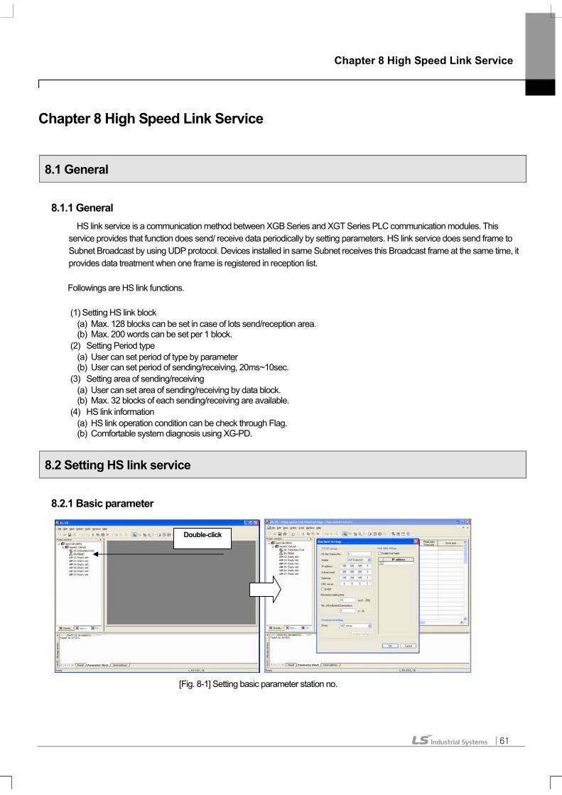
Chapter 8 High Speed Link Service
61
Chapter 8 High Speed Link Service
8.1 General
8.1.1 General HS link service is a communication method between XGB Series and XGT Series PLC communication modules. This
service provides that function does send/ receive data periodically by setting parameters. HS link service does send frame to Subnet Broadcast by using UDP protocol. Devices installed in same Subnet receives this Broadcast frame at the same time, it provides data treatment when one frame is registered in reception list. Followings are HS link functions. (1) Setting HS link block
(a) Max. 128 blocks can be set in case of lots send/reception area. (b) Max. 200 words can be set per 1 block.
(2) Setting Period type (a) User can set period of type by parameter (b) User can set period of sending/receiving, 20ms~10sec.
(3) Setting area of sending/receiving (a) User can set area of sending/receiving by data block. (b) Max. 32 blocks of each sending/receiving are available.
(4) HS link information (a) HS link operation condition can be check through Flag. (b) Comfortable system diagnosis using XG-PD.
8.2 Setting HS link service
8.2.1 Basic parameter
[Fig. 8-1] Setting basic parameter station no.
Double-click

Chapter 8 High Speed Link Service
62
8.2.2 HS link parameter (1) Setting communication module
[Fig. 8-2] Setting communication module in HS link parameter
(a) Select HS link 01 or HS link 02 on project window as the left screen of [Fig. 8-2], double-click it. (b) Double-clicking shows communication module information setting window as the right screen of [Fig.8-2].
[Fig. 8-3] Finishing HS link communication module setting
(c) Select the desired period of communication as the left screen of [Fig. 8-3]. (d) Clicking enter key shows block setting screen as the right screen of [Fig. 8-3].
Double-click
Select period
Select slot
HS link window

Chapter 8 High Speed Link Service
63
(2) Setting HS link sending block
[Fig. 8-4] Setting HS link Sending Block station type and mode
(a) Set station type ‘MASTER’ as the left screen of [Fig. 8-4]. (b) Select mode ‘Send’ as the right screen of [Fig. 8-3].
[Fig. 8-5] Setting HS link sending block station no. and block no.
(c) When an user selects sending as the left screen of [Fig. 8-5], it sets setting station no. in basic parameter. (d) Input block no. as the right screen of [Fig. 8-5].
[Fig. 8-6] Finishing HS link sending block data size setting
Select station type Select ‘Send’
Station no.
Input block no.
Input Read area Input data size

Chapter 8 High Speed Link Service
64
(e) Input READ area as the left screen of [Fig. 8-6]. READ area is each area of XGB CPU module. (f) Inputting word size of READ area as the right screen of [Fig. 8-6] finishes setting sending block .
(3) Setting HS link receiving block
[Fig. 8-7] Setting HS link receiving block station type and mode
(a) Set station type ‘MASTER’ as the left screen of [Fig. 8-7] (b) Select mode ‘Receive’ as the right screen of [Fig. 8-7]
[Fig. 8-8] Setting HS link receiving block station no. and mode
(c) Input station no. as the left of [Fig. 8-8]. This station no. is the number of destination device sending the block.
(d) Input block no. as the right screen of [Fig. 8-8]. It receives when the received frame is same as the block no.
Select station type Select ‘Receive’
Input station no.
Input block no.

Chapter 8 High Speed Link Service
65
[Fig. 8-9] Setting HS link receiving block station no. and mode
(e) Input save area as the left screen of [Fig 8-9]. Save area is the data saving area when each area of XGB CPU module receives the frame of block no. (f) Inputting word size of Read area as the right screen of [Fig. 8-9] finishes setting receiving block.
[Fig. 8-10] Finishing HS link receiving block data size setting
Input save area Input data size

Chapter 8 High Speed Link Service
66
(4) HS link enable
[Fig. 8-11] HS link enable
(a) Connecting it through XG-PD, click link enable on On-line menu. (b) Select HS link 01 or HS link 02.
[Fig. 8-12] Finishing HS link enable
(c) Click check box, then click write button. (d) When the message’s outputted, clicking enter key starts HS link communication.

Chapter 8 High Speed Link Service
67
8.3 HS Link Flag
HS link service exchanges between over 2 stations of communication modules. To verify the reliability of read data from destination station through HS link, HS link service provides HS link information to user. Communication module provides HS link information synthesizing receiving data by the time every some general interval And it verifies if the HS link operates in good condition followed by the user’s assigned parameter. HS link service is composed of followings. (1) Run- Link (_HSxRLINK): It shows communication network overall information, (2) Overall information of Link-Trouble (_HSxLTRBL) (3) _HSxSTATE, _HSxTRX, _HSxMOD, _HSxERR: Individual information. It shows each communication status by 64 registered
item in parameter User can use upper information in Key word type for programming. And by using HS information monitor function, user can monitor the status of HS link. Operating many PLCs by using HS link, user should do the operation after verifying the reliability of Send/Receive data with understanding Run-Link, Link-Trouble, etc. [Table 8-13] shows HS link information function and definition.
8.3.1 HS link flag classification
Classification Run-Link Link-TroubleSend/Receive
status Operation
Mode Error HS link status
Information type Overall Overall Individual Individual Individual Individual
Keyword name (x=HS Link No.)
_HSxRLINK _HSxLTRBL _HSxTRX[n] (n=0..64)
_HSxMOD[n] (n=0..64)
_HSxERR[n] (n=0..64)
_HSxSTATE[n] (n=0..64)
Data type Bit Bit Bit-Array Bit-Array Bit-Array Bit-Array
Monitor availability Yes Yes Yes Yes Yes Yes
Program usability Yes Yes Yes Yes Yes Yes
[Fig. 8-13] HS link flag
8.3.2 HS link flag introduction (1) Run-Link Flag Overall information, it shows if HS link operates in good condition by the user’s assigned parameter. It keeps ‘On’ by the time of permitting ‘Off’ when it is ‘On’ once, and it is ’On’ under following conditions. (a) When the permitting link is On’. (b) When all parameter registration item setting is normal. (c) When every data which is included in parameter registration item Send/Receive as the setting period. (d) Status of every setting destination station in parameter is RUN and at the moment there’s no error.
(2) Trouble-Link Flag (a) It shows if HS link operates in good condition by the user’s assigned parameter. (b) In the status of ‘On’ of Run-Link, if Run-Link is out of ‘On’ condition, it becomes ‘On’ and it does ‘Off’ when it
recovers.
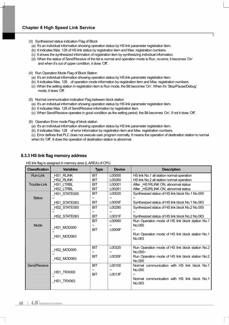
Chapter 8 High Speed Link Service
68
(3) Synthesized status indication Flag of Block (a) It’s an individual information showing operation status by HS link parameter registration item. (b) It indicates Max. 128 of HS link status by registration item and Max. registration numbers. (c) It shows the synthesized information of registration item by synthesizing individual information. (d) When the status of Send/Receive of the list is normal and operation mode is Run, no-error, it becomes ‘On’
and when it’s out of upper condition, it does ‘Off’.
(4) Run Operation Mode Flag of Block Station (a) It’s an individual information showing operation status by HS link parameter registration item. (b) It indicates Max. 128 of operation mode information by registration item and Max. registration numbers. (c) When the setting station in registration item is Run mode, the Bit becomes ‘On’. When it’s ‘Stop/Pause/Debug’
mode, it does ‘Off’.
(5) Normal communication indication Flag between block station (a) It’s an individual information showing operation status by HS link parameter registration item. (b) It indicates Max. 128 of Send/Receive information by registration item. (c) When Send/Receive operates in good condition as the setting period, the Bit becomes ‘On’, if not it does ‘Off’.
(6) Operation Error mode Flag of block station
(a) It’s an individual information showing operation status by HS link parameter registration item. (b) It indicates Max. 128 of error information by registration item and Max. registration numbers. (c) Error defines that PLC does not execute user program normally. It means the operation of destination station is normal when it’s ‘Off’. It does the operation of destination station is abnormal.
8.3.3 HS link flag memory address HS link flag is assigned in memory area (L AREA) of CPU.
Classification Variables Type Device Description Run-Link _HS1_RLINK
_HS2_RLINK BIT BIT
L00000 L00260
HS link No.1 all station normal operation HS link No.2 all station normal operation
Trouble-Link
_HS1_LTRBL _HS2_LTRBL
BIT BIT
L00001 L00261
After _HS1RLINK ON, abnormal status After _HS2RLINK ON, abnormal status
_HS1_STATE000 ~ _HS1_STATE063
BIT ~ BIT
L00020 ~ L0005F
Synthesized status of HS link block No.1 No.000 ~ Synthesized status of HS link block No.1 No.063
Status
_HS2_STATE000 ~ _HS2_STATE063
BIT ~ BIT
L00280 ~ L0031F
Synthesized status of HS link block No.2 No.000 ~ Synthesized status of HS link block No.2 No.063
_HS1_MOD000 ~ _HS1_MOD063
BIT ~ BIT
L00060 ~ L0009F
Run Operation mode of HS link block station No.1 No.000 ~ Run Operation mode of HS link block station No.1 No.063
Mode
_HS2_MOD000 ~ _HS2_MOD063
BIT ~ BIT
L00320 ~ L0035F
Run Operation mode of HS link block station No.2 No.000~ Run Operation mode of HS link block station No.2 No.000
Send/Receive
_HS1_TRX000 ~ _HS1_TRX063
BIT ~ BIT
L00100 ~ L0013F
Normal communication with HS link block No.1 No.000 ~ Normal communication with HS link block No.1 No.063
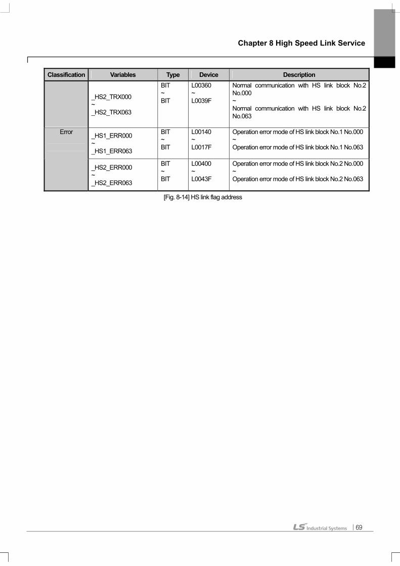
Chapter 8 High Speed Link Service
69
Classification Variables Type Device Description
_HS2_TRX000 ~ _HS2_TRX063
BIT ~ BIT
L00360 ~ L0039F
Normal communication with HS link block No.2 No.000 ~ Normal communication with HS link block No.2 No.063
_HS1_ERR000 ~ _HS1_ERR063
BIT ~ BIT
L00140 ~ L0017F
Operation error mode of HS link block No.1 No.000~ Operation error mode of HS link block No.1 No.063
Error
_HS2_ERR000 ~ _HS2_ERR063
BIT ~ BIT
L00400 ~ L0043F
Operation error mode of HS link block No.2 No.000~ Operation error mode of HS link block No.2 No.063
[Fig. 8-14] HS link flag address

Chapter 9 Remote Communication Control
70
Chapter 9 Remote Communication Control
9.1 General
Remote communication control is a function is for programming, download of user program, program debugging,
monitoring, etc in network system where PLCs are connected with each other Enet by remote control without moving the
physical connection status of XD-PD.
It is convenient for easy access to each device from a place without repositioning when network-connected devices are separated
far. Communication service function creates the following logical path to attain its purpose.
PLC [1]IP: 192.168.91.188
PLC [2]IP: 192.168.91.189
PLC [n]IP: 192.168.91.190
RS232
XG-PD또는 XG5000
로컬 접속 이더넷 통신을 사용한 논리 접속(리모트 접속)
PLC [1]IP: 192.168.91.188
PLC [2]IP: 192.168.91.189
PLC [n]IP: 192.168.91.190
RS232
XG-PD또는 XG5000
로컬 접속 이더넷 통신을 사용한 논리 접속(리모트 접속) [Fig. 9-1]
A network is supposed where RS-232C cable is connected to PLC #1, and PLC #1, PLC #2, PLC #N are connected with each other via Enet. In order to access the contents of PLC #1 in [Fig.9-1], do local connection on XG-PD online menu, then access the contents of PLC #1. After finishing access, to access the contents of PLC #N, disconnect the access with PLC #1.
Then, select PLC # N (Station No: N, FEnet slot of PLC #1: 2), accessing it connects logical connection between RS- 232C and Enet.
This status as processed identically to connection with RS-232C as moved to PLC #N station is available to execute all functions of program, download, debugging and monitoring as in PLC #1.
Furthermore, when a PC with operating XG-PD is installed with Enet module is installed, and it’s connected to same network with the PLC, it can directly do remote 1 connection with PLC without local connection through RS-232C,
With this remote communication service, easy access to PLC position in the distance is available without moving thereto, which is useful for maintenance of PLC system.
Local connection Logical connection via Ethernet (remote connection)

Chapter 9 Remote Communication Control
71
9.2 XG-PD Setting and Connection
All PLCs connected with XGT network are available to connect each PLCs by XG-PD communication service. XG-PD remote connection is composed of remote 1 connection (Hereafter, referred to as remote 1) and remote 2 Connection (Hereafter, referred to as remote 2) Following shows remote1 and remote 2
[Fig. 9-2] XG-PD remote connection
[Fig. 9-2] shows examples of remote1 (PLC B) and remote 2 (PLC E) in a system which composed of 2 networks.

Chapter 9 Remote Communication Control
72
9.2.1 Remote 1 (RS-232C Cable)
For remote 1, XG-PD shall be in off-line status. In this status, select ‘Option’ from the project menu. It shows option dialogue
box. Then, select ‘Option’ tap.
[Fig. 9-3] XG-PD remote connection option selecting
(1) Connection type (a) Select local connection type. [Fig. 9-3] shows a local connection by using RS-232C
(b) Select the communication port from user PC port.
(c) Following section explains the case of Enet user.
(d) Refer to the user manual of each communication module.
(2) Connection stage (a) It decides local or remote 1 or remote 2 for connecting PLC.
(b) Select remote 1.
[Fig. 9-4] XG-PD remote 1

Chapter 9 Remote Communication Control
73
(3) Connecting (a) Select Rnet, Fdnet, Cnet, FEnet, FDEnet by the remote 1 network type.
(b) [Fig. 9-4] shows remote 1 through FEnet.
(c) Select XGL-Enet.
(4) Base No. (a) Assign Base No. that is installed with FEnet I/F module for remote connection.
(5) IP address (a) FEnet I/F module IP that installed in destination station PLC for remote 1 in network 1
(b) Assign address. [Fig.9-4] shows the connection to FEnet I/F module of IP address 168.192.12.13.
(6) Slot
(a) It shows the position of communication module which is connected to network 1 from local PLC by RS-232C.
(b) In [Fig. 9-4], FEnet I/F module is installed in PLC A. Select the slot no.0.
(c) Select enter on (b), then select connection online menu.
(d) The status of finishing remote 1 is same as the logical connection status with local connection by moving
RS-232C cable.
(e) User can use all function of online menu. (But user can’t do when the type of PLC and present open project
CPU are not matched)
Remark 1) Caution for remote connection
Do remote connection after programming which is for the destination CPU type. If the CPU type is not a right match, it only do limited functions, it can not do program upload, download and monitoring.

Chapter 9 Remote Communication Control
74
9.2.2 Remote 2 (RS-232C Cable)
Remote 2 sets connection stage/remote2 from project/option/connection option. [Fig.9-5] shows remote 2, it’s an example of connection to Fnet I/F module of PLC E through FEnet I/F module of PLC B.
To do remote 2, at the connection stage of project/option/connection option, select remote 2, then it shows the following box.

Chapter 9 Remote Communication Control
75
[Fig. 9-5] XG-PD remote 2
Other parts are same as the step of remote 1. Only the step of remote 2 explains.
(1) Network type setting
(a) Select XGT FEnet by network remote 2.
(b) Network type of remote 1 and remote 2 have no relevance.
(2) Slot No. setting (a) In Network 2 , the position of module which installed in remote 2 station PLC(PLC B).
(b) The position shall be inputted as Slot No.
(3) The status of finishing remote 1 is same as the logical connection status with local connection by moving RS-232C. User can use all function of online menu.

Chapter 9 Remote Communication Control
76
9.2.3 Direct remote 1 on Enet connecting PC
When a PC with operating XG-PD connects to PLC on network, remote 1 by Enet is available without connecting RS-232C to PLC CPU.
PLC [1]IP: 192.168.91.188
PLC [2]IP: 192.168.91.189
PLC [n]IP: 192.168.91.190
PC 또는노트북
XG-PD또는 XG5000
이더넷 통신을 사용한 1단 논리 접속(리모트 1단 접속)
PLC [1]IP: 192.168.91.188
PLC [2]IP: 192.168.91.189
PLC [n]IP: 192.168.91.190
PC 또는노트북
XG-PD또는 XG5000
이더넷 통신을 사용한 1단 논리 접속(리모트 1단 접속)
PLC [1]IP: 192.168.91.188
PLC [2]IP: 192.168.91.189
PLC [n]IP: 192.168.91.190
PC 또는노트북
XG-PD또는 XG5000
이더넷 통신을 사용한 1단 논리 접속(리모트 1단 접속)
[Fig. 9-6] Remote 1 system through PC
[Fig. 9-6] shows the status that PC and PLC are connected by Enet. In this case, XG-PD can connect all PCs on network without using RS-232C. Local connection is not needed, remote 1 can be executed for all PLCs.
To execute direct remote 1 through Enet, select connection option and change the settings as following boxes.
1 logical connection via Ethernet (remote 1 connection)
PC or Laptop

Chapter 9 Remote Communication Control
77
[Fig. 9-7] Direct remote 1 on PC
(1) Connecting type (a) Select connecting type. [Fig. 9-7] shows the Enet connection without using RS-232C. Select Enet.
(2) Connection stage (a) Decide remote 1 or remote 2 for the connection with PLC. In this case, select remote 1.
(3) IP address (a) Record IP address of FEnet I/F module for connection.
(4) After(3), all steps are same as the steps of the case using RS-232C. Select enter at this status, select connection on online menu.
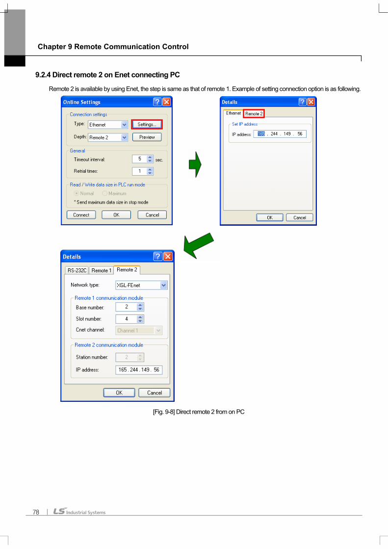
Chapter 9 Remote Communication Control
78
9.2.4 Direct remote 2 on Enet connecting PC
Remote 2 is available by using Enet, the step is same as that of remote 1. Example of setting connection option is as following.
[Fig. 9-8] Direct remote 2 from on PC

Chapter 9 Remote Communication Control
79
Remark 1) Cautions for Remote 1 connection and Remote 2 connection
(1) Following menu item can’t be available when XG-PD present open project and remote 1 and 2 connected CPU type are not well matched.
a) Program and Write each parameter b) Program and Read each parameter c) Monitor d)Set Flash memory e)Enable Link setting f) I/O information g) Force I/O h) Skip I/O
(2) In case of programming by connecting XG-PD as remote 1 and 2, open the right project of connecting station and then execute connection.
(3) Remote connection provides only by remote 2. Over remote 2 is not available.

Chapter 10 Troubleshooting
80
Chapter 10 Troubleshooting This chapter describes defects and errors that may occur in system operation, their causes and actions to take against. If any error occurs on XGB Fast Enet I/F module, its related details can be checked through the procedures below. Any discretionary or disassembly is not allowed.
Error Details Actions 1. Check if CPU unit’s correctly connected with FEnet module. 2. Check the upper and lower fixing lever position. Position close after connecting module.
Connecting with CPU unit is not correct, the power can be supplied and module can’t operate.
3. Check voltage (DC 24V) and capacity of power. When the consumption current of expansion module on CPU unit is over the rated capacity, module can’t operate.
RUN LED ‘Off’ after module powered on
4. Check if communication module is correctly recognized through XG-PD. Check it by using system diagnosis.
1. Check if CPU unit’s correctly connected with FEnet module. Connecting with CPU unit is not correct, data can’t be exchanged normally. I/F LED ‘No-Flicker’ or ‘Off’ after
module powered on 2. Check if communication module is correctly recognized through XG-PD.
Check it by using system diagnosis.
TX/RX LED ‘No-Flicker’ or ‘Off’ after network connection
1. Check communication cable and network status 2. Check if RJ45 connector connected correctly 3. Check if LINK LED flicker
Connection of communication cable and RJ45 connector are not correct, Send/Receive is not available.
All LEDs ‘On’ after module powered on
Module malfunction, Repairs should be followed
1. Check communication speed (Auto/10/100M-TX). Communication speed should be same as that of destination device.
When the setting communication speed is as same or Auto on network, communication is available.
2. Check IP address setting. Valid IP address on network should be set. When IP address overlapped on network or invalid IP, communication is unavailable.
3. Check driver (Dedicated, Modbus TCP/IP) setting Same protocol with destination device should be used.
Data Read/Write unavailable during dedicated service
4. Check if IP of destination device is registered on host table. When host table is enable, IP address of destination is not registered,
communication is not available. 1. Check communication speed (Auto/10/100M-TX). Communication speed should be same as that of destination device.
When the setting communication speed is as same or Auto on network,
communication is available.
Send/Receive unavailable during HS link service
2. Check IP address setting. Valid IP address on network should be set. When IP address overlapped on network or invalid IP, communication is
unavailable.

Chapter 10 Troubleshooting
81
Error Details Actions 3. Check if HS link parameter setting When parameter’s not set, station no. is overlapped, wrong block setting, wrong
block no., communication is not available. 4. Check link enable setting
With link enable setting, frame can be sent. 1. Check communication speed (Auto/10/100M-TX)
When the setting communication speed is as same or Auto on network, communication is available.
2. Check IP address setting When IP address overlapped on network or invalid IP, communication is
unavailable. 3. Check if P2P parameter setting Setting P2P parameter channel, block makes communication available. 4. Check destination IP address in P2P channel setting
When IP address of destination device is invalid, communication is not available. 5. Check driver setting
When communication protocol is same as destination device on the right channel, communication is available.
6. Check link enable setting With link enable setting, frame can be sent.
7. Check if operation of operation condition Setting operation condition should be ‘On’.
Send/Receive unavailable during P2P service
8. Check operation mode of CPU Operation condition of CPU should be ‘On’.

Warranty
82
Warranty
1. Warranty Period The product purchased will be guaranteed for a period of 18 months upon manufactured.
2. Warranty Coverage Against the defect found during the Warranty Period specified above, this product will be repaired or exchanged partially. However,
please understand that such cases as described below will be excluded from the Warranty Coverage.
(1) If the defect is caused by unsuitable condition, environment and treatment or other reason than specified in the user’s manual.
(2) If the defect is caused by other parts than LS product. (3) If the product is remodeled or repaired by others than LS or its designated service center. (4) If the product is used with other procedures than originally intended. (5) If the defect is caused by a reason unexpected under the scientific and technical standard when released from LS. (6) If the defect is caused by a natural calamity or fire which LS is not responsible for.
3. Since the warranty details above are to guarantee the PLC unit only, the customers are strongly recommended to use the product
after due consideration of safety for system configuration or product application.
Environmental Policy LS Industrial Systems Co., Ltd supports and observes the environmental policy as below.
LS Industrial Systems considers the environmental preservation as the preferential management subject and every staff of LS Industrial Systems use the reasonable endeavors for the pleasurably environmental preservation of the earth.
LS Industrial Systems’ PLC unit is designed to protect the environment. For the disposal, separate aluminum, iron and synthetic resin (cover) from the product as they are reusable.
Environmental Management About Disposal