Embed Size (px)
Citation preview

Best Available Techniquesfor Pollution Prevention and Control in the
European Sulphuric Acid and Fertilizer Industries
Booklet No. 3 of 8:
PRODUCTION OF SULPHURICACID
2000
European Sulphuric Acid Association (ESA)A sector group of CEFIC
EFMAEuropean Fertilizer Manufacturers’ Association
Ave. E van Nieuwenhuyse 4
B-1160 Brussels
Belgium


Best Available Techniquesfor Pollution Prevention and Control in the
European Sulphuric Acid and Fertilizer Industries
Booklet No. 3 of 8:
PRODUCTION OF SULPHURICACID
Copyright 2000 – ESA/EFMA
This publication has been prepared by member companies of theEuropean Sulphuric Acid Association (ESA) in co-operation with theEuropean Fertilizer Manufacturers’ Association (EFMA). NeitherAssociation nor any individual member company can accept liabilityfor accident or loss attributable to the use of the information given inthis Booklet.

2
Hydrocarbon feed
Water
Air
Ammonia
Booklet No. 1
No. 2
Water
Air
Water
Sulphur
Water
Phosphate rock
Phosphoric Acid
Sulphuric Acid
Nitric Acid
No. 5
Urea
UAN
AN
CAN
NPK(nitrophosphate route)
NPK(mixed acid route)
K, Mg, S,micronutrients
Calciumcarbonate
Phosphate rock
K, Mg, S,micronutrients
No. 6
No. 7
No. 8No. 4
No. 3
Phosphate rock

3
Content
PREFACE 4
1. GENERAL INFORMATION 61.1 General Information About the Sulphuric Acid Industry 61.2 Scope of this BAT Booklet 7
2. APPLIED PROCESSES AND TECHNIQUES 82.1 Raw Material Preparation including Storage and Handling 82.2 Material Processing 102.3 Product Finishing 112.4 Use of Auxiliary Chemicals/Materials 122.5 Intermediate and Final Product Storage 132.6 Energy Generation/Consumption, Other Specific Utilities 142.7 Gas Cleaning of Metallurgical Off-gases 152.8 Handling of Waste Gas/Stack Height 15
3. PRESENT CONSUMPTION/EMISSION LEVELS 163.1 Consumption of Energy/Raw Materials/Water Inputs and Waste 163.2 Emission Levels 163.3 Environmental Aspects 17
4. CANDIDATE BATS 214.1 Available Techniques 214.2 Environmental Performance 354.3 Economic Performance 39
5. BEST AVAILABLE TECHNIQUES 415.1 BAT for the Different Types of Sulphuric Acid Processes 415.2 BAT for Contact Processes 445.3 Cross Media Impact 48
6. EMERGING TECHNIQUES 49
7. CONCLUSIONS AND RECOMMENDATIONS 507.1 Conclusions 507.2 Recommendations 52
8. REFERENCES 54
GLOSSARY AND UNITS 56
APPENDIX Inputs and Outputs 57

4
PREFACE
The European Sulphuric Acid Association (ESA) and the European Fertilizer ManufacturersAssociation (EFMA) have prepared recommendations on Best Available Techniques (BAT)in response to the EU Directive on integrated pollution prevention and control (IPPCDirective). This Booklet (based on Report EUR 13006 EN) has been prepared by ESA andEFMA experts drawn from member companies. The recommendations cover the productionprocesses of Sulphuric Acid and Oleum and reflect the industry perception of which tech-niques are generally considered to be feasible and present achievable emission levels associ-ated with the manufacturing of the products.
The Booklet uses the same definition of BAT as that given in the IPPC Directive. BATcovers both the technology used and the management practices necessary to operate a plantefficiently and safely. The focus is primarily on the technological processes, since good man-agement is considered to be independent of the process route. The industry recognises, how-ever, that good operational practices are vital for effective environmental management andthat the principles of Responsible Care should be adhered to by all companies.
Two sets of BAT emission levels are given:-
– For existing production units where pollution prevention is usually obtained by revampsor end-of-pipe solutions
– For new plants where pollution prevention is integrated in the process design
The emission levels refer to emissions during normal operations of typical sized plants.Other levels may be more appropriate for smaller or larger units and high emissions mayoccur in start-up and shut-down operations and in emergencies. Only the more significanttypes of emissions are covered and the emission levels given do not include fugitive emis-sions and emissions due to rainwater. The emission levels are given both in concentration val-ues (ppm or mg.m-3) and in load values (emission per tonne 100% wt sulphuric acid). Itshould be noted that there is not necessarily a direct link between the concentration valuesand the load values.
It is recommended that the given emission levels should be used as reference levels for theestablishment of regulatory authorisations. Deviations should be allowed as governed by:-
–
Local environmental requirements
, given that the global and inter-regional environ-ments are not adversely affected
–
Practicalities and costs of achieving BAT
–
Production constraints
given by product range, energy source and the availability ofraw materials

5
If authorisation is given to exceed these BAT emission levels, the reasons for the deviationshould be documented locally. Existing plants should be given ample time to comply withBAT emission levels and care should be taken to reflect the technological differencesbetween new and existing plants when issuing regulatory authorisations, as discussed in thisBooklet.
There is a wide variety of methods for monitoring emissions. The emission levels given aresubject to some variance, depending on the method chosen and the precision of the analysis.It is important when issuing regulatory authorisations, to identify the monitoring method(s) tobe applied. Differences in national practice may give rise to differing results, as the methodsare not internationally standardised. The given emission levels should not, therefore, be con-sidered as absolute but as references which are independent of the methods used.
ESA would also advocate a further development for the authorisation of sulphuric acidplants. The plants can be complex, with the integration of several production processes andthey can be located close to other industries. Thus there should be a shift away from authori-sation governed by concentration values of single point emission sources. It would be betterto define maximum allowable load values from an entire operation, e.g. from a total site area.However, this implies that emissions from single units should be allowed to exceed the valuesin the BAT recommendation, provided that the total load from the whole complex is compa-rable with that which can be deduced from there. This approach will enable plant manage-ment to find the most effective environmental solutions and would be to the benefit of ourcommon environment.
Finally, it should be emphasised that each individual member company of ESA is responsi-ble for deciding how to apply the guiding principles of the BAT Booklet on the Production ofSulphuric Acid.

6
1. GENERAL INFORMATION
1.1 General Information About the Production of Sulphuric Acid
More sulphuric acid is produced than any other chemical in the world. In Western Europe in1997 over 19 million tonnes were produced, the total production world-wide being estimatedat around 150 million tonnes. About half of this output is produced in North America,Western Europe and Japan [20], [21].
Table 1 World Production and Consumption
The output of sulphuric acid at base metal smelters today represents about 20% of all acidproduction. Whereas in 1991 smelter acid production amounted to 27.98 millions tonnes, it iscalculated that the output in the following decade will have grown to reach 44.97 millionstonnes in 2001. Smelter acid will be more than 25% of world sulphuric acid production com-pared to some 18% in 1991.
Table 2 Production of Sulphuric Acid in the Countries of the European Community
Sulphuric acid is produced in all the countries of Europe with the major producers beingGermany, Spain, France, Belgium and Italy. These countries accounting for 70% of the totalEuropean production. It is used directly or indirectly in nearly all industries and is a vital com-modity in any national economy. In fact, sulphuric acid is so widely used that its consumptionrate, like steel production or electric power, can be used to indicate a nation’s prosperity.
In Million tonnes H 2SO4 1992 1993 1994 1995 1996 1997
World sulphuric acid production 145.7 132.5 137.9 148.9 151.3 155.6
World sulphuric acid consumption 147.1 132.8 138.8 150.1 153.3 157.5
In Million tonnes H 2SO4 1992 1993 1994 1995 1996 1997
Belgium/Luxembourg 1.836 1.535 1.515 2.174 2.067 2.160
Finland 1.351 1.361 1.373 1.376 1.479 1.570
France 3.132 2.515 2.227 2.382 2.263 2.242
Germany 3.800 3.515 3.380 3.530 3.978 3.496
Greece 0.620 0.588 0.630 0.515 0.615 0.675
Italy 1.725 1.423 1.228 1.344 1.588 1.590
Netherlands 1.080 1.000 1.073 1.113 1.060 1.040
Norway 0.587 0.564 0.585 0.609 0.594 0.666
Spain 2.420 2.176 2.348 2.265 2.786 2.810
Sweden 0.567 0.497 0.518 0.485 0.620 0.630
United Kingdom 1.568 1.269 1.225 1.293 1.196 1.205

7
Most of its uses are actually indirect in that the sulphuric acid is used as a reagent ratherthan an ingredient. The largest single sulphuric acid consumer by far is the fertiliser industry.Sulphuric acid is used with phosphate rock in the manufacture of phosphate fertilisers.Smaller amounts are used in the production of ammonium and potassium sulphate.Substantial quantities are used as an acidic dehydrating agent in organic chemical and petro-chemical processes, as well as in oil refining. In the metal processing industry, sulphuric acidis used for pickling and descaling steel; for the extraction of copper, uranium and vanadiumfrom ores; and in non-ferrous metal purification and plating. In the inorganic chemical indus-try, it is used most notably in the production of titanium dioxide.
Certain wood pulping processes for paper also require sulphuric acid, as do some textileand fibres processes (such as rayon and cellulose manufacture) and leather tanning. Other enduses for sulphuric acid include: effluent/water treatment, plasticisers, dyestuffs, explosives,silicate for toothpaste, adhesives, rubbers, edible oils, lubricants and the manufacture of foodacids such as citric acid and lactic acid.
Probably the largest use of sulphuric acid in which this chemical becomes incorporatedinto the final product is in organic sulphonation processes, particularly for the production ofdetergents. Many pharmaceuticals are also made by sulphonation processes.
1.2 Scope of this BAT Booklet
Many processes of sulphuric acid production have been developed according to the largenumber of sources of raw materials (SO2), and their specific characteristics. The present doc-ument deals also with the production of oleum. It is possible to draw a general diagram ofsulphuric acid production distinguishing the two fundamental steps of the process (seeFigure 1):-
– Conversion of SO2 into SO3
– Absorption of SO3
H2SO4
Oleum
SO2 ➞ SO3
SO2 formation Water
Source of SO2(clean and dry)
Conversion ofSO2
Absorption ofSO3
Possible dilution with airSO2 H2SO4 mist/SO3
SO3 ➞ H2SO4 ➞ Oleum
Sulphuric acid productionOleum production
Figure 1 – General Diagram of Sulphuric Acid Production.

8
2. APPLIED PROCESSES AND TECHNIQUES
2.1 Raw Material Preparation including Storage and Handling
2.1.1 Sulphur storage and handling
Liquid sulphur is a product of the desulphurisation of natural gas and crude oil by the Claus-Process, with the cleaning of coal flue gas as a second source. The third way is the melting ofnatural solid sulphur (Frash-process) but this is not in frequent use because there are manydifficulties in removing the contaminants.
The following is a typical analysis of molten sulphur (quality: bright yellow):-
Ash max. 0.015% weightCarbon max. 0.02% weightHydrogen sulphide ca. 1-2mg.kg-1
Sulphur dioxide 0mg.kg-1
Arsenic max. 1mg.kg-1
Mercury max. 1mg.kg-1
Water max. 0.05% weight
Liquid sulphur is transported in ships, railcars and trucks made of mild steel. Special equip-ment is used for all loading and unloading facilities. Liquid sulphur is stored in insulated andsteam heated mild steel tanks. The tank is is equipped with submerged fill lines to avoid staticcharges and reduce agitation in the tank. The ventilation of the tanks is conventionally free. Afurther fact is less de-gasing of hydrogen sulphide and sulphur dioxide. All pipes and pumpsare insulated and steam heated. The normal temperature level of the storage and handling isabout 125-145°C.
2.1.2 Ore storage and handling
2.1.2.1 Pyrites
Normally pyrites is produced in a flotation process, which means that the concentrate is rela-tively finely ground with a moisture content dependent on how much energy is spent in thedrying step. The analyses are variable within following ranges:-
Table 3 Range of Analyses of Pyrites
Element Content Content in one specific pyrite
Sulphur weight % 30-52 50-52
Iron weight % 26-46 45
Copper weight % up to 2.7 max. 0,10
Zinc weight % up to 3.0 max. 0,10
Arsenic weight % up to 10.0 max. 0,06
Water weight % 5-9 5

9
A number of other metals are present in small quantities. The right hand column shows theanalyses of one certain pyrite.
Pyrites should be covered during storage and transport to avoid dust. Outside storage cangive rise to two problems depending on the climate:-
– Dust problems can be expected under dry conditions. A dusty atmosphere, especiallyinside buildings can cause a fire or an explosion under the right conditions
– Water in contact with pyrites becomes acidic under wet conditions. This water has to beremoved and treated before loading for transport to the recipient. With too high a mois-ture content the pyrites will give clogging problems in the internal transport system atthe plant
2.1.2.2 Metal sulphide ores
Approximately 85% of primary copper is produced from sulphur ores and therefore sulphur isa by-product of the majority of copper processes. Copper ore concentrates are produced in theflotation process and consist mainly of copper pyrites or chalcopyrite (CuFeS2) but may alsocontain pyrites, chalconite, burnite, cuprite and other minerals. A typical concentrate compo-sition is 26-30% Cu, 27-29% Fe and 28-32% S.
Copper concentrates are usually processed by pyrometallurgical methods. Ores and con-centrates are delivered to site by road, rail or ship. Copper concentrates are usually stored inclosed buildings. Silo systems are used for the intermediate storage and preparation of theblend. Dust collection and abatement systems are used extensively during the unloading, stor-age and distribution of solid material.
Zinc and lead are for a major part, produced from sulphur ores and thus sulphuric acid isalso a final product of treating these ores in metallurgical processes. In the first step the basicores are treated in a flotation process to become concentrates, which are then shipped toSmelters for metal recovery. The concentrates are usually processed by metallurgical meth-ods to remove sulphur. Ores and concentrates are delivered to site by road, train or ship.
The storage on site may be in the open air or in covered buildings depending on local con-ditions. In every case silo systems and dust collection systems such as bag filters are used toavoid dust propagation during intermediate storage in the process and the preparation of theblend.
2.1.3 Organic spent acids
Spent acids from different operations such as steel pickling, titanium dioxide production ororganic sulphonation reactions have such a variety of compositions that it is not possible todefine a set of general rules for preparation, storage and handling. Each case must be treatedindividually with special consideration given to dilution and any impurities which may affectall operations. Experience and know-how are of paramount importance.
Spent acids come mainly from organic chemical production. Sulphuric acid is mostly usedas a catalyst and needs to be replaced with fresh concentrated acid when diluted and/orsaturated with organics. Alkylation processes in refineries and nitration and sulphonation

10
processes in the chemical industry generate large amounts of spent acids which, after regener-ation, become clean acid which can be recycled in any process.
Spent acids can be received by barges, road and rail tankers. Chemical analysis and physi-cal tests are carried out before unloading to be sure the product meets the acceptance contractand to avoid any chemical reaction in storage when mixing spent acids from differentprocesses. Storage vessels are bunded. The storage gas phases are connected to the thermaldecomposition furnace through non flammable systems on account of the risks due to theorganics vapour pressure, to some dissolved sulphur containing products and to potential NOxemissions. Nitrogen is used to blanket the gas phase to avoid any oxygen intrusion. Materialsof construction depend on the strength of the spent acid. Corrosion resistant pumps and pipesare used for the feeds to the furnace.
2.1.4 H2S or other sulphur containing gases
Off-gases containing H2S and CS2 are formed during the production of textile fibres, whichare made in the viscose process. Off-gases containing H2S or SO2, depending on the process,are formed during the production of synthesis gas using fuel oil as a feedstock.
2.1.5 SO2 gases from different sources
Gases containing up to 90% SO2 from the production of organic compounds such assulphonates and sulphites or from the combustion of gases containing H2S, can be used as asource of SO2 after the separation of organic compounds.
2.1.6 Sulphate salts
Ferrous sulphate is obtained in large quantities as its heptahydrate (FeSO4.7H2O) during theregeneration of pickling liquors or as a side product in the TiO2 process via the sulphate route.
2.2 Material Processing
2.2.1 Conversion of SO2 into SO3
The design and operation of sulphuric acid plants are focused on the following gas phasechemical equilibrium reaction with a catalyst:-
SO2 + 1⁄2 O2 SO3 ∆H = –99 kJ.mol-1
This reaction is characterised by the conversion rate, which is defined as follows:-
conversion rate =
×
100 (%)
Both thermodynamic and stoichiometric considerations are taken into account in maximis-ing the formation of SO3. The Lechatelier-Braun Principle is usually taken into account indeciding how to optimise the equilibrium. This states that when an equilibration system issubjected to stress, the system will tend to adjust itself in such a way that part of the stress isrelieved. These stresses are, for example, a variation of temperature, pressure, or the concen-tration of a reactant.
SO2 in – SO2 out
SO2 in

11
For SO2/SO3 systems, the following methods are available to maximise the formation ofSO3:-
– Removal of heat – a decrease in temperature will favour the formation of SO3 since thisis an exothermic process
– Increased oxygen concentration
– Removal of SO3 (as in the case of the double absorption process)
– Raised system pressure
– Selection of the catalyst to reduce the working temperature (equilibrium)
– Increased reaction time
Optimum overall system behaviour requires a balance between reaction velocity and equi-librium. However, this optimum also depends on the SO2 concentration in the raw gas and onits variability with time. Consequently, each process is more or less specific for a particularSO2 source.
2.2.2 Absorption of SO3
Sulphuric acid is obtained from the absorption of SO3 and water into H2SO4 (with a concen-tration of at least 98%).
The efficiency of the absorption step is related to:-
– The H2SO4 concentration of the absorbing liquid (98.5-99.5%)
– The range of temperature of the liquid (normally 70°C-120°C)
– The technique of the distribution of acid
– The raw gas humidity (mist passes the absorption equipment)
– The mist filter
– The temperature of incoming gas
– The co-current or counter-current character of the gas stream in the absorbing liquid
SO3 emissions depend on:-
– The temperature of gas leaving absorption
– The construction and operation of the final absorber
– The device for separating H2SO4 aerosols
– The acid mist formed upstream of the absorber through the presence of water vapour
2.3 Product Finishing
2.3.1 Dilution of absorber acids
The acid produced, normally 95.5%-96.5% or 98.5%-99.5%, is diluted with water or steamcondensate down to the commercial concentrations: 25%, 37%, 48%, 78%, 96% and 98%H2SO4. The dilution can be made in a batch process or continuously through in-line mixing.

12
2.3.2 SO2-Stripping
A small amount of air is blown through the warm acid in a column or tower to reduce theremaining SO2 in the acid to < 20mg SO2.kg-1. The air containing SO2 is returned to theprocess.
2.3.3 Purification
Sulphuric acid from the start up of acid plants after long repair may be contaminated andclouded by insoluble iron sulphate, or silicate from bricks or packing. The acid can be filteredusing conventional methods. Filter elements are required in the filling lines for tanker or rail-way loading to maintain quality.
2.3.4 Denitrification
A number of different methods are used for the denitrification of sulfuric acid and oleum.Various chemicals are used to reduce nitrosylsulphuric acid (NOHSO4) or nitrate to N2 orNxOy (See Table 4). The reactant must be added in stoichiometric amounts.
Table 4 Methods of Denitrification
2.3.5 Decolourisation
Acid produced from smelter plants or from acid regeneration plants can contain hydrocarbonsor carbonaceous material, which is absorbed in sulphuric acid. This causes a ‘black’ colour.The decolourisation is known as “acid bleaching”.
2.4 Use of Auxiliary Chemicals/Materials
2.4.1 Catalysts
When producing sulphuric acid by the contact process an important step is to produce sulphurtrioxide by passing a gas mixture of sulphur dioxide and oxygen over a catalyst according tothe equation:-
SO2 + 1⁄2 O2 SO3 – ∆ H
Method of denitrification Special conditions Effect In tail gas
Urea Absorber/tanks +/only <80% acid N2
Dihydrazinedisulphate 40% Absorber/tanks +++/acid and oleum N2, N2O
Amidosulphonic acid 15% Absorber/tanks +++/only 50-99.5% acid N2Hydroxylammoniumsulphate
SO2 saturated acid 78% H2SO4/ +++/only acid/ NOxseparated tower water balance
Method of decolourisation Special conditions Effect
Hydrogen peroxide solution <60% Absorber/tanks +++/acid and oleum

13
Without a catalyst this reaction needs a very high temperature to have a realistic rate. Theequilibrium is however in favour of SO2 – formation at higher temperatures which makes theconversion very poor.
Of all substances tested for catalytic activity toward sulphur dioxide oxidation only vanadi-um compounds, platinum and iron oxide have proven to be technically satisfactory. Todayvanadium pentoxide is used almost exclusively.
Commercial catalysts contain 4-9 wt % vanadium pentoxide, V2O5, as the active compo-nent, together with alkali metal sulphate promoters. Under operating conditions these form aliquid melt in which the reaction is thought to take place. Normally potassium sulphate isused as a promoter but in recent years also caesium sulphate has been used. Caesium sulphatelowers the melting point, which means that the catalyst can be used at lower temperatures.The carrier material is silica in different forms.
The catalyst components are mixed together to form a paste and then usually extruded intosolid cylindrical pellets, rings or star-rings which are then baked at elevated temperatures.Ring (or star-ring) shaped catalysts, which are mostly used today, give a lower pressure dropand are less sensitive to dust blockage.
The lower temperature limit is 410-430°C for conventional catalysts and 380-390°C forcaesium doped catalysts. The upper temperature limit is 600-650°C above which, catalyticactivity can be lost permanently due to reduction of the internal surface.
The average service life for the catalyst is about 10 years. Service life is generally deter-mined by catalyst losses during the screening of the catalyst which is necessary from time totime to remove dust [1], [2].
2.5 Intermediate and Final Product Storage
There is no air pollution problem connected with the storage, handling and shipping of sul-phuric acid because of the very low vapour pressure of H2SO4 in normal temperature condi-tions. The handling of pure SO3 and oleum requires safety procedures and management inorder to avoid atmospheric pollution in the case of an accidental release.
Important considerations with regard to the ancillary operations referred to above, are asfollows:-
– The receipt, handling and storage of powdered raw materials should be carried out so asto minimise the emission of dust. Liquid and gaseous feeds should be carefully con-tained to prevent the emission of odorous fumes or gases
– Oleum and SO3 storage and handling operations, which are often linked with H2SO4production, should be installed with a means of controlling fume emissions. Ventingshould be directed towards acid tanks or scrubbing systems. Installations should be builtby following the best engineering practice. The emissions can condense and solidify incool areas so this must be very carefully guarded against to prevent over-pressurisationof storage tanks

14
– During storage and handling of sulphuric acid, leaks may have an impact on the soil oron waters. Precautions have to be taken in order to reduce the possibility and the gravityof these leaks. See reference [3] for the minimum requirements
2.6 Energy Generation/Consumption, Other Specific Utilities
The process steps: burning sulphur, roasting sulphidic ores, SO2 conversion and SO3 absorp-tion are exothermic processes. This means that from a technical point of view, installationsfor removing energy are of great importance for the production of sulphuric acid. This is cou-pled most effectively with energy winning in different levels and forms. Energy winning isdependent on the process strategy for the target products, for the local conditions, and for apossible relationship to other production processes. The age of the production units is moreimportant than energy generation/consumption because materials of construction and specificbuildings fix the technical possibilities for energy optimisation. A sulphur burning process inconjunction with double absorption is the most energy efficient.
The different energy-winning techniques are:-
– All techniques of steam generation as used in electrical power generation with specialapparatus such as super-heater, economiser or steam boiler for sulphur burning
– Steam generation by the inter-pass absorption with temperatures from 110°C to 180°Cand steam pressures from 1.5barabsto 11barabs
– Steam turbines with power generation up to 15MWh (1,250t.d-1 100% H2SO4 Plant)
– Water preheating in the end absorption from 40°C to 80°C
Special programs are used for the optimisation of the process (e.g. cost savings and win-ning energy).
An essential characteristic of a conventional cold-gas plant (metallurgical gases) is thatalmost all the energy is discharged as waste heat at low temperature. Double absorptionprocesses based on metallurgical gases, differ from hot-gas plants based on sulphur combus-tion in that cold feed gases must be heated to the converter-inlet temperature using the energyliberated in the oxidation of sulphur dioxide. See Appendix.
At a feed-gas concentration of 8.5% SO2 and a dryer inlet temperature of 30-40°C about2.7GJ of thermal energy is liberated per tonne of sulphuric acid (5.4GJ in the case of sul-phuric acid produced from elemental sulphur). This corresponds to a thermal output of 31Mw for a 1,000t.d-1 plant. About 45% of the total energy is discharged through the intermedi-ate absorber acid cooling system, 23% through the final absorber acid cooling system andabout 22% through the dryer-acid cooling system.
In terms of heat recovery, in a conventional cold-gas double-absorption plant for process-ing relatively low-grade sulphur dioxide containing feed gases, there is no excess high tem-perature heat that can be used for the generation of high pressure steam. However, where thesulphuric acid plant is linked to a modern smelter, high SO2 is available and to increase theoutput of high pressure steam, low temperature heat from the absorber acid circuits can beused for preheating the boiler feed water.

15
2.7 Gas Cleaning of Metallurgical Off-gases
Gases containing SO2 from all metallurgical processes are cleaned before the contact processto remove the following components:-
– Fumes or aerosols formed by condensation of volatile metal components such as Zn, Pb,Sb, Bi, Cd and their chlorides, sulphates and oxides
– Volatile gaseous metals such as As, Se, Hg and their compounds
– Gaseous non-metallic compounds such as HF, HCl, SO3, CO
After cleaning, small amounts of impurities are absorbed in sulphuric acid or emitted withthe tail gas through the stack. CO is oxidised to CO2 in the contact process and gases fromcombustion processes also contain CO2.
Table 5 shows the different metallurgical off-gases, the main disposals and the method ofcleanup.
Table 5 Disposal and Clean-up of Metallurgical Off-gases
2.8 Handling of Waste Gas/Stack Height
The height of the exhaust stack determines the maximum SO2/SO3 concentration value in theambient air surrounding a sulphuric acid plant. It is also well known that this concentration iswidely fluctuating in space and time due to the thermo-aerodynamic conditions of the low-level atmosphere (0 to 500m). These conditions can vary due to the following factors:-
– Vertical temperature and humidity structure
– Wind speed and direction
– Turbulence of the atmosphere
– Sunshine intensity etc.
Proposals for stack heights could consequently have a questionable character.
For the time being, every Member State has its own method for estimating the height ofstacks. In the future, it is foreseen that a specific Technical Note on this topic will be pub-lished by the European Commission.
Off-gas from Main disposal Cleanup system
“CuS” smelters Hg, HF ESP, Gas scrubber with HgCl2or Na2S3O3/HgS
“PbS” smelters Hg ESP, Gas scrubber with HgCl2
“ZnS” smelters Hg ESP, Gas scrubber with HgCl2
“Ni” smelters Se Gas scrubber

16
3. PRESENT CONSUMPTION/EMISSION LEVELS
3.1 Consumption of Energy/Raw Materials/Water Input and Waste
The Appendix gives typical inputs/outputs for different types of a 4-bed contact process pertonne 100% H2SO4.
The types of process are:-
– Sulphur-burner, pyrites roasting, “CuS” roasting, “ZnS” roasting, “PbS” roasting
– H2SO4 regeneration, “FeSO4” roasting
3.2 Emission Levels
Calculated SO2 Emission
0
2,000
4,000
6,000
8,000
10,000
12,000
14,000
5 6 7 8 9 10 11 12
SO2 content before bed 1 [Volume %]
[mg
SO
2/N
m3 ]
99.8 % conversion rate 99 % conversion rate 97 % conversion rate
Figure 2 – Calculated SO2 Emissions in mg.Nm-3 in Relation to the SO2 Contentbefore Bed 1.

17
3.3 Environmental Aspects
3.3.1 Emissions into air/water, waste generation
3.3.1.1 Emissions into air CO2, SOx, NOx
3.3.1.1.1 SO3 emissions
Origins:-
– Bad absorption efficiency
– Vapour pressure of sulphuric acid/oleum
Minimisation techniques:-
Absorption improvements:-
– Absorbing tower design (velocity)
– Acid distribution (flow and repartition)
– Packing efficiency
– Acid temperature (vapour pressure)
3.3.1.1.2 H2SO4 emissions
Origins:-
– Tower design
– Mist formation
– Vapour pressure
Minimisation techniques:-
– Droplet carry-over
– Absorbing tower design (gas velocity, acid distribution)/demisters(mesh pads or candles)
– Mist filter
– Process control:-
– ESP efficiency
– Drying tower efficiency
– Gas temperature upstream absorption
– NOX content in the gases
– Acid temperature at the bottom of absorption tower
– Acid vapour pressure (temperature)
– High Efficiency demisters 50mg.Nm-3 (particles > 0.5µ)

18
3.3.1.1.3 SO2 emissions
Origins:-
– Bad conversion efficiency
– Gas bypassing (acid cross bleed or convector)
Minimisation techniques without additional process:-
Gases:-
– Composition (O2, SO2, inerts…)
– Velocities through catalyst and repartition
– Cooling quality (heat exchangers or air cooling)
– Operating pressure
– Acid cross-bleeds (SO2 stripping, SO2 gases drying processes)
– Temperature
Catalyst:-
– Converter design
– Number of beds
– Catalyst quality and quantity
– Converter loading
SO2-Minimisation techniques with additional process:-
– Without by-product: Single absorption double absorption (if gases are higherthan 6% SO2)
– SO2 weak H2SO4 possible to recycle: Activated carbon oxidation process/H2O2 process
– With co- or by-product:-
– NH3 scrubbing, Co product Ammonium sulphate
– NaOH scrubbing, Co product Sodium sulphate
– Ca(OH)2 scrubbing, Co product Calcium sulphate (gypsum)
– Mg(OH)2 scrubbing, Co product Magnesium sulphate
– Other processes – neutralisation absorption, bioconversion – exist but are less devel-oped and depend on the specific site
3.3.1.2 Emissions into water
– Energy release from cooling
– Accidental leakage
– Waste water treatment plants must be able to deal with heavy metals
– Emissions of noise by air cooling
– Water treatment for steam production

19
3.3.1.3 Solid wastes
3.3.1.3.1 Sulphuric acid spent catalysts
Methods for disposing of spent catalyst are:-
– Metal recovery
The vanadium content of the catalysts can be reclaimed for further use. This service isusually provided by the catalyst manufacturer who will have access to a reclamationoperation. The metal can be recycled as vanadium salts or as ferrovanadium for steelproduction.
In all cases of the recycling versions it is very important that the spent catalyst has a lowcontent of arsenic. A typical analysis for spent catalyst:-
V2O5: min. 3% weightK2O: max. 10% weightP: max. 0.5% weightSn, Pb, As, Sb, Bi, Cu, Zn, Cd, Hg: max. 0.1% weight
– Landfill Disposal:-
Two types of disposal are available
Fixation: The catalyst is ‘fixed’ in an inert matrix, usually concrete or glass (also knownas vitrification) prior to controlled deposit in a suitably licensed landfill site. The fixationprocess is designed to prevent metals leaching into the landfill site.
Direct landfilling: The catalyst is deposited directly into a suitably licensed landfill sitein compliance with national legislation. It is common practice to mix the catalyst withlime to neutralise residual acidity.
3.3.1.3.2 Wastes from packing and lining
Waste from the chemical industry is always handled with care. Waste from sulphuric acidproduction, packing, lining and scrap-iron is always handled in the same way as waste fromother chemical production plants. That means that where it is necessary, the waste is checkedfor impurities before a decision is made on how to handle it. There are usually no problems innormal sulphuric acid production
3.3.2 Consumption of water/energy and other resources
Sulphuric acid production is one of the few chemical processes where more energy is normal-ly produced than is used in the process. In many cases sulphuric acid plants are used as theenergy source for the production processes for other chemicals that require energy. TheAppendix shows the energy outputs from different plants.
Sulphuric acid production also has the advantage that there is no formation of carbon diox-ide compared with fuel and natural gas and energy is “green” compared to other energy pro-duction due to the fact that the energy is a by-product. Overall the process is a net producer ofenergy, although the amount of recovery is a function of the level of quality of this energy.

20
3.3.2.1 Consumption of water
All acid plants have measures to control the use of water for cooling and adjusting the con-centration in the acid system. The cooling system is normally a closed water circuit or itincludes a measurement of the pH before discharge to waste. The use of water in the acid sys-tem is important to ensure the right concentration in the absorption tower to prevent acid mistin the stack.
Boiler feed water for steam production requires special pre-treatment depending on the dif-ferent sources such as ground water or drinking water. Treatments include anion and/or cationexchange and conditioning with ammonia, sodium hydroxide, hydrazine or phosphates.Water quality including pH and conductivity must be fully controlled. About 95% of thewater is used for steam production and the remainder of the boiler water which is mostlyalkaline can be discharged to drain after neutralisation. In the interests of economy all uncont-aminated water condensates should be collected and used for new steam production.
3.3.2.2 Energy consumption
Sulphuric acid production is always a net producer of energy. The quality of the energy pro-duced is a function of site requirements. Examples of the different kinds of energy producedare: steam at different pressures for chemical plants, power generation or city heating; or hotwater for use in greenhouses or fish farms.
3.3.2.3 Other resources
Regeneration, recycling and evaporation are different ways to prevent spent acid becoming awaste and a problem for the environment. A sulphuric acid plant to process the tail gas frommetal roasting prevents the emission of sulphur dioxide to the atmosphere.
3.3.3 Accidental pollution
There is always a risk of accidental pollution when chemicals are produced and handled. Themore common a chemical, the more information is available about the different hazards andthe lower the risk of accidental pollution. The highest risk for accidental pollution is duringthe transportation of the product and that is covered under the different transport regulationssuch as those of ADR/RID and IMO. There is also a risk of pollution from the storage of sul-phuric acid and different plants have different systems to collect leaks and spillages depend-ing on guidelines for the storage of acid.
Gas leaks are not normally a problem as they are handled by various monitoring and con-trol systems, which measure the SO2 content in the air.
3.3.4 Areas of concern
The most important issue is the transportation of the product and that is covered under theregulations of ADR/RID and IMO. There is a risk to personnel during the loading andunloading of sulphuric acid if it is mishandled. All producers are responsible for the personalsafety of their employees and and have different systems of work to ensure proper handling.

21
3.3.5 Multimedia complexity
Emissions of sulphur dioxide into the air may deposit on the soil and contribute to a lower pH.
SO2 scrubbing gives rise to a by-product disposal problem which will depend on the typeof by-product. For example gypsum may be disposed of to landfill and ammonium sulphatemay be sold or recycled.
4. CANDIDATE BATS
4.1 Available Techniques
The general presentation of the technique of production of sulphuric acid is divided into twoparts as the techniques for the conversion of SO2 to SO3 and of absorption of SO3 depend onthe concentration of SO2 in the feed gas entering the installation and on the variability of SO2concentration.
Sources of SO2
– Sulphur burning
– Pyrites roasting
– Metal sulphide roasting and smelting
– Sulphuric acid regeneration
– Metal sulphate roasting
– Combustion of H2S or other sulphur containing gases
– Other processes
Sulphuric acid production
Acid production is divided into two different groups depending on the level of SO2 in theprocess gas.
Poor gas processes with > 3 Vol. % SO2:-
– Single contact process
– Double contact process
– Wet Contact Process (WCP)
Tail gas processes with < 3 Vol. % SO2:-
– Modified Lead Chamber Process (MLCP)
– H2O2 process
– Activated Carbon
– Other processes

22
4.1.1 Overview of techniques applicable to sources of SO2
Figures 3.1 to 3.6 in the Appendix detail the characteristics of the principal sources of SO2dependent on the different processes. Table 6 gives an overview of techniques that have apositive effect on, that is reduce, the emissions from the manufacture of sulphur dioxide.
Table 6 Techniques Reducing the Emissions
4.1.1.1 Combustion of Sulphur
The combustion of sulphur which is obtained either from natural deposits or from de-sul-phurisation of natural gas or crude oil, is carried out in one-stage or two-stage sulphur com-bustion units at between 900 and 1800°C. The combustion unit consists of a combustionchamber followed by a process gas cooler. The SO2 content of the combustion gases is gener-ally up to 18% by volume and the O2 content is low (but higher than 3%).
The gases are generally diluted to 10-11% before entering the conversion process. In theinlet gas to the converter the ratio SO2/O2 should not be higher than 0.8 to achieve a high con-version efficiency. This means that the highest percentage of SO2 should not exceed 11% in a4-bed double contact (no caesium) plant to achieve an average conversion rate of 99.6%.
4.1.1.2 Pyrites roasting
Fluid-bed roasters are the preferred equipment for pyrites roasting. They are much superior toother types of equipments in terms of process technology, throughput rates and economy.Two by-products, iron oxide and energy are also produced when roasting pyrites to get SO2gas. 1 tonne of acid needs 0.5 tonnes of pyrites. The SO2 content of the gases is generallybetween 6 and 14% with zero O2 in the gas. The SO2 content in the gases is slightly variableover time due to the heterogeneous character of the raw material (pyrites).
The gases are always treated in 3-4 cleaning steps using cyclones, bag filters, scrubbers andelectrostatic precipitators with a high efficiency. Waste water from the scrubbing must betreated before discharge. The clean gas is diluted with air to 6-10% and dried before enteringthe conversion process.
Techniques Process Fuel ESP Filters SOxcontrol selection
Sulphur burning
X X X
Ore roasting/smelting
X X X X X
H2SO4 Regeneration
X X X X X
Sulphate roasting
X X X X X
Combustion of H2S
X X X X
23
4.1.1.3 Metal sulphide roasting/smelting
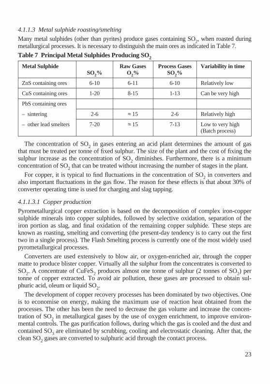
Many metal sulphides (other than pyrites) produce gases containing SO2, when roasted duringmetallurgical processes. It is necessary to distinguish the main ores as indicated in Table 7.
Table 7 Principal Metal Sulphides Producing SO2
The concentration of SO2 in gases entering an acid plant determines the amount of gasthat must be treated per tonne of fixed sulphur. The size of the plant and the cost of fixing thesulphur increase as the concentration of SO2 diminishes. Furthermore, there is a minimumconcentration of SO2 that can be treated without increasing the number of stages in the plant.
For copper, it is typical to find fluctuations in the concentration of SO2 in converters andalso important fluctuations in the gas flow. The reason for these effects is that about 30% ofconverter operating time is used for charging and slag tapping.
4.1.1.3.1 Copper production
Pyrometallurgical copper extraction is based on the decomposition of complex iron-coppersulphide minerals into copper sulphides, followed by selective oxidation, separation of theiron portion as slag, and final oxidation of the remaining copper sulphide. These steps areknown as roasting, smelting and converting (the present-day tendency is to carry out the firsttwo in a single process). The Flash Smelting process is currently one of the most widely usedpyrometallurgical processes.
Converters are used extensively to blow air, or oxygen-enriched air, through the coppermatte to produce blister copper. Virtually all the sulphur from the concentrates is converted toSO2. A concentrate of CuFeS2 produces almost one tonne of sulphur (2 tonnes of SO2) pertonne of copper extracted. To avoid air pollution, these gases are processed to obtain sul-phuric acid, oleum or liquid SO2.
The development of copper recovery processes has been dominated by two objectives. Oneis to economise on energy, making the maximum use of reaction heat obtained from theprocesses. The other has been the need to decrease the gas volume and increase the concen-tration of SO2 in metallurgical gases by the use of oxygen enrichment, to improve environ-mental controls. The gas purification follows, during which the gas is cooled and the dust andcontained SO3 are eliminated by scrubbing, cooling and electrostatic cleaning. After that, theclean SO2 gases are converted to sulphuric acid through the contact process.
Metal Sulphide Raw Gases Process Gases Variability in timeSO2% O2% SO2%
ZnS containing ores 6-10 6-11 6-10 Relatively low
CuS containing ores 1-20 8-15 1-13 Can be very high
PbS containing ores
– sintering 2-6 ≈ 15 2-6 Relatively high
– other lead smelters 7-20 ≈ 15 7-13 Low to very high(Batch process)

24
4.1.1.3.2 Zinc production
Zinc production is based on the treatment of zinc concentrates, mainly sulphides, with anaverage composition of sulphide sulphur: 30-33%, Zn: 50-60%, Fe: 1-12%, Pb: 0.5-4% andCu: 0.1-2%.These concentrates are desulphurised in a first step.
After the desulphurisation step the product (calcine) is treated for zinc recovery mainly in ahydrometallurgical process and for a minor part also in a pyrometallurgical process. Thehydro way consists of leaching this calcine, purifying the enriched zinc solution and subse-quently recovering pure zinc metal by electrolysis. In the pyrometallurgical way, conditionedcalcine is reduced in a shaft furnace (ISF) and the zinc vapours are condensed in a splash con-denser. This crude zinc is further refined in a distillation column.
More specifically, the preliminary desulphurisation step takes place mainly in a fluidisedbed roaster or alternatively in a sinter plant. The SO2 content of the gases is about 5 to 10%.After heat recovery in a waste heat boiler with the production of steam, the gases are dedustedby electrostatic precipitation (ESP), cooled down in scrubbing towers and subsequentlydemercurified in a specific scrubbing process. The cleaned SO2 gases are treated and convert-ed to sulphuric acid in a double contact process in modern plants or in a single contactprocess for older plants.
4.1.1.3.3 Lead production
Primary lead is produced predominantly from lead and lead/zinc concentrates and to a smallerextent from other sources, such as complex lead/copper concentrates. Concentrate compo-sitions may therefore vary over a rather wide range: 10-80% Pb, 1-40% Zn, 1-20% Cu,1-15% Fe, 15-35% S. Somewhat different processes have been developed and are used for anoptimum recovery of the various metals present in the feed.
Whichever smelting technique is used, desulphurisation is always one of the objectives ofthe first treatment stages. It is carried out on belt sinter machines in those cases where a shaftfurnace is the actual smelting step, or in flash or bath smelting furnaces in the other processes.
From this variety of feed materials and consequently of techniques, it should be clear thatthe characteristics of the SO2-containing gas will differ markedly from case to case. Fromcontinuous operations, such as sinter machines, the SO2-concentration can be kept fairly con-stant and depending on the actual feed mix it can be between 6 and 9%. From batch opera-tions, it will vary between 0 and 15%, depending on the process stage. The average concen-tration may be between 2.5 and 10%, depending on the actual feed mix and the appliedtechnique.
The gas cleaning circuit will always include ESP and scrubbers. Energy recovery can bepractised in some cases of bath smelting but a specific mercury removal step, on the gas or onthe acid, may be necessary in others. The double absorption process is largely used, particu-larly when SO2 concentrations are high and constant. When low and very varying SO2 con-centrations are inevitable, or where those streams cannot be integrated in more steady gasstreams from other processes on the site, single absorption is more appropriate.

25
4.1.1.4 Regeneration of sulphuric acid
Thermal decomposition of spent sulphuric acids to give sulphur dioxide is achieved in a fur-nace at temperatures around 1,000°C. Spent acids come from processes where H2SO4 oroleum is used as a catalyst (alkylation, nitration, sulphonation etc.) or from other processeswhere H2SO4 is used to clean, dry and remove water.
Gas phase thermolysis of sulphuric acid is represented by the overall equation:-
H2SO4 SO2 + H2O + 1⁄2 O2 ∆ H = +202 kJ.mol-1
Spent acids are atomised in very small droplets to achieve a good thermal decomposition.Energy is provided by the organics from the spent acids and by additional energy from natur-al gas, fuel oil or coke. Preheating the combustion air reduces the amount of fuel needed.Furnaces can be horizontal (fixed or rotating) or vertical.
The SO2 content in the gases mainly depends on the composition of the spent acids. Thewater and organics content affect the gas composition which can vary from 2 to 15%.Sulphur, pure or waste, can generally be added to adjust the SO2 content and to try to avoidlarge variations. The most part of the energy from the combustion gases is recovered as steamin a Waste Heat Boiler. Downstream, the gases are cleaned, demisted and dried before goingto the converter. The O2/SO2 ratio is important to get a conversion rate of SO2 to SO3 whichis as high as possible. Upstream of the converter, the gases are reheated to the ignition tem-perature through gas/gas heat exchangers using the conversion heat. A double absorptionprocess can be used only if the SO2 content of the gases is high enough (about 8%) at the con-verter inlet.
Conversion rates:-
– Single absorption
SO2 content at the converter inlet
8%
with O2/SO2 ratio of 1.1:
98%
SO2 content at the converter inlet from
5 to 8%
with O2/SO2 ratio of 1.1:
97 to 98%
SO2 content at the converter inlet below
5%
with O2/SO2 ratio of 1.1:
96 to 97%
– Double absorption
When achievable, double absorption leads to conversion rates from
99 to 99.6%
Double absorption is considered as the BAT for new plants. For existing plants, a singleabsorption can be advantageously combined with an ammonia scrubber, the by-productobtained being either sold on the market or recycled in the furnace.
4.1.1.5 Sulphate roasting
Decomposition of sulphates, for example iron sulphate, is carried out in multiple-hearth fur-naces, rotary kilns or fluid bed furnaces at over 700°C with the addition of elemental sulphur,pyrites, coke, plastic, tar, lignite, hard coal or oil as fuel compensator. The SO2 content of thegases obtained is dependent on the type of fuel. After cleaning and drying, the SO2 content isabout 6% and the variability in time of the SO2 content is high.

26
During the first step, the heptahydrate is dehydrated at 130-200°C by flue gases in spraydryers or fluid-bed dryers to a monohydrate or mixed hydrate. In a second step, the material isdecomposed at about 900°C.
The gases thus obtained contain about 7% by volume of sulphur dioxide. Today it is com-mon practice for ferrous sulphate to be decomposed in a fluid-bed pyrites roasting furnace at850°C or more. Elemental sulphur, coal or fuel oil may be used as supplementary fuels. Thesulphur dioxide containing gas leaving the furnace is cooled in a waste heat boiler to about350-400°C and is subsequently passed to the gas cleaning system. The cleaned gases are fedto the sulphuric acid plant.
A mixture of sulphates (metallic or ammonium) and eventually sulphuric acid, resultingfrom the concentration of acidic wastes from titanium oxide production or from organicsulphonations, can similarly be processed in a fluid bed reactor or a furnace. In individualcases, ferrous sulphate is also decomposed in multiple-hearth furnaces with flue gases fromfuel oil or natural gas combustion.
4.1.1.6 Combustion of sulphur containing gases
Combustion of hydrogen sulphide (H2S) or similar gases is achieved in a fixed furnace atabout 1000°C. Combustion heat is higher than with sulphur combustion. Two different waysare used to process the gases to SO3 and H2SO4:-
– A dry process where the water is eliminated by condensation and then drying and thegases are processed as in the spent acid regeneration process
– A wet process in which the gases are processed with all the water and steam. At the endof the process, the absorption tower is replaced by a condenser where the control of tem-perature allows the production of 96% H2SO4, the most part of water being dischargedto the atmosphere
The conversion rates are comparable to those for sulphur burning plants.
4.1.1.7 Tail gas scrubbing
SO2 abatement by scrubbing consists of a chemical reaction between SO2 and a basic liquidsolution. This operation is achieved generally in a gas/liquid contact packed tower or a scrub-ber. A liquid circulation loop is operated from the bottom to the top of the tower, where theliquid is distributed above the packing.
The gases enter the bottom part of the tower, contact and react with the basic liquid solu-tion on the packing. The SO2 content in the outlet gases is achieved by controlling the pH ofthe solution and by adding more or less basic concentrated solution into the liquid circulationloop. One or two reaction steps may be needed depending on the inlet and outlet SO2 contentand the basic product used (ammonia, caustic soda, magnesium or calcium hydroxides, etc.).The resulting by-products (ammonium-, sodium-, magnesium-, or calcium-, sulphate, sulphiteand bisulphite) can be sold or may have to be disposed of.

27
4.1.2 Overview of techniques applicable to sulphuric acid production
This section refers to existing plants which may (or may not) be up-graded, although notreaching the specifications of new plants.
4.1.2.1 Overview
The six process routes are the principal process routes that are available. The following dataon production processes have been presented in detail in the previous paragraphs and aresummarised in Table 8 using an O2/SO2 ratio of about 1 ± 0.2 (possibly 0.8 to 3).
Table 8 Sulphuric Acid Production Processes for New Plants
[1] when sulphur burning[2] SO3 + H2SO4 expressed as SO3[3] possible emissions of NOx[4] for existing plants the conversion rate is 98%[5] per tonne of acid produced
Table 9 gives an overview of techniques that have a positive effect on, that is reduce, theemissions from the manufacture of sulphuric acid
Table 9 Techniques Reducing the Emissions
NEW PLANTS SO2 content in Conversion rate State of the artfeed gas daily average emission for new plants SO3(% vol) (%) [2]
Single contact
6-10 98.5% [4] 0.4kg.t-1 [5]3-6 97.5% to 98.5%
Double contact
6-12 99.6% [1] 0.1kg.t-1 [5]
Wet contact process
0.05-7 98.0% < 10ppmv SO3
Process based on NOx
0.05-8 nearly 100% [3] No data
H2O2 Process
> 99.0% Very low
Techniques Process Single Double Catalysts Filters SOx NOxcontrol contact contact
Sulphur burning
X X X X X X
Ore roasting
X X X X X X
H2SO4regeneration
X X X X X X X
Sulphate roasting
X X X X X
Incineration of H2S
X X X X X X X

28
4.1.2.2 Single contact process (single absorption)
The contact process without intermediate absorption is only used in new plants to processSO2 gases with low and widely varying SO2 contents. The SO2-containing gases, which havebeen carefully cleaned and dried, are oxidised to sulphur trioxide in the presence of catalystscontaining alkali and vanadium oxides. The sulphur trioxide is absorbed by concentrated sul-phuric acid in absorbers, preceded by oleum absorbers where necessary. In the absorbers, thesulphur trioxide is converted to sulphuric acid by the existing water in the absorber acid. Theabsorber acid is kept at the desired concentration of approximately 99% by wt. by addingwater or dilute sulphuric acid as shown in Figure 3.
The single contact process is generally used with inlet gases containing 3 to 10% SO2. Innew plants, the conversion efficiency is about 98.5% as a daily average and can be upgradedto 99.1% depending on good design and the use of specially adapted catalyst doped with cae-sium. In existing plants, it is difficult to obtain better than 98.0% conversion but, in someexisting plants, a conversion efficiency of 98.5% has been achieved.
4.1.2.3 Double contact process (double absorption)
In the double contact process, a primary conversion efficiency of 80% to 93%, depending onthe arrangement of the contact beds and of contact time, is obtained in the primary contactstage of a converter preceding the intermediate absorber. After cooling the gases to approxi-mately 190°C in a heat exchanger, the sulphur trioxide already formed is absorbed in theintermediate absorber in sulphuric acid with a concentration of 98.5 to 99.5% by weight. Theintermediate absorber is preceded by an oleum absorber if required. The absorption of the sul-phur trioxide brings about a considerable shift in the reaction equilibrium towards the forma-tion of SO3, resulting in considerably higher overall conversion efficiencies when the residualgas is passed through one or two secondary contact beds. The sulphur trioxide formed in thesecondary stage is absorbed in the final absorber.
The double contact processes including double absorption are shown in Figures 4, 5 and 6with the different raw materials – sulphur, non-ferrous ores and pyrites. In general, SO2 feedgases containing up to 12 Vol.% SO2 are used for this process. The conversion efficiency innew plants can reach about 99.6% as a daily average in the case of sulphur burning.
4.1.2.4 Wet contact process (WCP)
This process is not sensitive to the water balance and has been used to treat off-gas from amolybdenum smelter as well as being installed in two desulphurisation plants (one in a FlueGas Desulphurisation system, the other on an industrial boiler) currently under construction.An earlier version of the WCP technology was used to treat lean hydrogen sulphide gases.For all gas feeds, sulphurous components in the gas are converted to sulphuric acid withoutthe need to dry the gas first. [33].
When treating roaster off-gas, the off-gas is cleaned in a standard purification system andthen fed through a blower, which provides the pressure necessary to overcome the pressure

29
Fig
ure
3 –
Sin
gle
Abs
orpt
ion
Pro
cess
for
Spe
nt A
cid
Reg
ener
atio
n.
Fu
rnac
e
Bo
iler
Qu
ench
to
wer
Co
olin
g t
ow
er
Ele
ctro
sta
tic
pre
cip
itat
or
Dry
ing
to
wer
Mai
n g
as b
low
er
Gas
/gas
hea
t ex
chan
ger
Gas
/gas
hea
t ex
chan
ger
Gas
/gas
hea
t ex
chan
ger
Co
nve
rter
bed
1
Co
nve
rter
bed
2
Air
co
ole
r
Co
nve
rter
bed
3A
ir c
oo
ler
Co
nve
rter
bed
4A
ir b
low
er
Eco
no
mis
er
Ab
sorp
tio
n t
ow
er
Aci
d c
oo
ler
Fu
el
Air
S
pen
t ac
idS
ulp
hu
ric
acid
Ho
t ai
r

30
Fig
ure
4 –
Sul
phur
ic A
cid
Pla
nt (
Dou
ble
Cat
alys
is)
Bas
ed o
n S
ulph
ur C
ombu
stio
n.
Mai
n b
low
er
Dry
erW
aste
hea
tb
oile
rS
ulp
hu
r b
urn
er
Inte
r-m
edia
teab
sorb
er
Ole
um
abso
rber
Fin
alab
sorb
er
Sta
ck
Air
Su
lph
ur
Fee
dw
ater
Ste
am
Ole
um
20-
37%
H2S
O4
96-9
8%
Hea
tex
chan
ger
Hea
t ex
cha
ng
er
Hea
tex
chan
ger
Hea
tex
chan
ger
Hea
t ex
chan
ger
Co
nve
rter
bed
1
Co
nve
rter
bed
2
Co
nve
rter
bed
3
Co
nve
rter
bed
4
Wat
er

31
Figure 5 – Sulphuric Acid Plant (Double Catalysis) Based on Non Ferrous Ores.
Furnace
Waste heat boiler
Scrubber
Electrostatic precipitator
Converters
Cooling systems
Scrubber
Cooling tower
Drying tower
Blower
Fuel Air Cu concentrate
Cu matte
Electrostatic precipitator
Blower
Humidification T/VScrubbers
Wet electrostatic precipitator
Blower
Heat exchanger
Heat exchanger
Converter bed 1
Converter bed 2
Converter bed 3
Converter bed 4
Heatexchanger
Inter-mediateAbsorber
FinalAbsorberStack
H2SO4 96-98,5%
Heat exchanger
Water

32
Fig
ure
6 –
Typ
ical
Lay
out o
f a S
ulph
uric
Aci
d P
lant
(D
oubl
e C
atal
ysis
) B
ased
on
Pyr
ites.
Blo
wer
Roa
ster
Was
te h
eat b
oile
r
Cyc
lone
sSc
rubb
erES
PW
ater
trea
tmen
t
Air
Pyrit
esFe
ed w
ater
Dry
ing
tow
er
Mai
n bl
ower Fi
nal
abso
rber
Dilu
tion
Stac
k
Hea
tex
chan
ger
IRO
N-O
XID
E
Inte
rmed
iate
abso
rber
Ole
um-
abso
rber
Stea
m
Hea
tex
chan
ger
Hea
tex
chan
ger
Ole
um 2
5%
H2S
O4 9
4-96
%
Was
te w
ater
Con
vert
er b
ed 4
Con
vert
er b
ed 3
Con
vert
er b
ed 2
Con
vert
er b
ed 1
Hea
tex
chan
ger

33
drop across the system. The gas is preheated initially in the tower and, secondly, in a heatexchanger. It is next fed to a converter, where sulphur dioxide is oxidised over a catalyst tosulphur trioxide. A cooled reactor or an adiabatic reactor is used, depending on the condi-tions.
Sulphur trioxide-containing gas is then cooled in a gas-gas heat exchanger. Consequently,part of the sulphur trioxide reacts with the water vapour in the gas to form sulphuric acidvapour. Finally, the sulphuric acid vapour is condensed and concentrated, without acid mistformation, in a multi-tube falling film condenser. Cooling is provided by the cold feed gassupplied to the shell side.
The only utilities required are cooling water for the acid coolers, electricity for the blowerand fuel to enable autothermal operation if the feed gas contains below about 1.5-2.0% SO2.The conversion efficiency is about 98.5% as a daily average.
4.1.2.5 Pressure process
As the oxidation of SO2 is favoured by pressure, Pressure Contact Processes have been devel-oped in which the sulphur combustion, sulphur dioxide conversion and sulphur trioxideabsorption stages are effected at elevated pressure. Several parameters can influence the con-version efficiency by modifying the chemical equilibrium. Pressure is one of these parametersand this displaces the equilibrium to the right. One plant in France, a double-absorption plantwith a capacity of 550-575t.d-1 of H2SO4, has been designed with the pressure process in theearly 1970s and is still in operation. Usual sulphuric acid processes are operated at pressuresin the range of 0.2 to 0.6bar.
Two special advantages have been claimed for the pressure contact process compared withthe conventional double-absorption process:-
– The position of the chemical equilibrium in the sulphur dioxide oxidation reaction ismore favourable, allowing a higher conversion efficiency to be attained with a reducedamount of catalyst. The plant is reported to have achieved 99.80-99.85% conversion.The tail gas sulphur dioxide content is reported to be reduced to about 200-250ppm SO2.However, the high temperatures in the sulphur furnace increase the rate of formation ofnitrogen oxide
– Smaller equipment can be used because of the lower operating volumes of the convertergases. This reduces material and site area requirements and raises the capacity limit ofshop-fabricated equipment. The resulting capital cost savings are said to be about 10-17% in comparison with current double-absorption plants. However, in some countriesthese savings would be nullified by the cost of conforming to the requirements for extrawall thickness and higher-grade materials of construction laid down in the safety regula-tions relating to pressure vessels
The principal disadvantages of the pressure contact process compared with the convention-al double-absorption process is that it consumes more power and produces less steam.

34
4.1.2.6 Other processes
Other processes are defined as processes which yield sulphuric acid but which are not eco-nomically viable for large scale production for different reasons.
4.1.2.6.1 Unsteady state oxidation process
This new method of SO2 oxidation is based on a periodic reversal of the direction of the reac-tion mixture flow over the catalyst bed. The process was developed at the Institute ofCatalysis of the former USSR. Basically a large bed of catalyst is used as both a reversing,regenerating heat exchanger and as a catalytic reactor for the SO2 oxidation reaction.
Cold SO2 gas is fed into the catalyst bed and is heated to catalyst ignition temperature bythe heat stored in the bed. At this point the conversion reaction proceeds, producing heat. Theheat is absorbed by the catalyst in the bed, increasing its temperature. When the front comesclose to the exit side of the bed, the flow through the reactor is reversed. Flow reversals aremade every 30-120 minutes. The main advantage of the unsteady state process is that theoperating line for the first bed is almost vertical, giving first bed conversion of about 80-90%at a low exit temperature. The process is auto-thermal at low (0.5-3%) SO2 gas concentra-tions.
The process is in operation in several plants in Russia and other Eastern European countries.
4.1.2.6.2 H2O2 Process
The conversion of SO2 to SO3 can be achieved by the use of H2O2 at a sulphuric acid concen-tration of 70%. Conversion efficiency is higher than 99% but the cost of H2O2 makes this anexpensive process for sulphuric acid production. However, since the process leaves no waste,it is very useful for tail gas scrubbing where especially difficult local conditions cannot toler-ate the emission even from an installation as efficient as the best contact plant. The H2O2 isused either directly or is produced by electrolysing H2SO4 to peroxydisulphuric acid in the“Peracidox” process.
4.1.2.6.3 The modified lead chamber process
The Modified Lead Chamber Process is able to treat gases with low SO2 content (as low as0.05%) up to 8%. The process is also able to treat gases containing a mixture of SO2 andNOx. From the chemical point of view, the process is a development of lead chamber sul-phuric acid technology, in which nitrogen oxides are used to promote sulphuric acid produc-tion directly from sulphur dioxide through the formation of an intermediate, nitrosyl sulphuricacid. Widely used in the early 1900s, this technology has been largely superseded by the con-tact process.
After dust removal and purification, the sulphur dioxide-containing gas is fed through adenitrification system, where final traces of nitrogen oxides remaining in the sulphuric acidare removed. It is then passed through the Glover tower where the bulk of the nitrogen oxidesare removed from the sulphuric acid. Sulphur dioxide is then absorbed from the gas streaminto sulphuric acid (59 to 66%) in a packed tower. In both the Glover and absorption towers,the gas flow is counter current to the liquid flow.The final step of the process is the removal of

35
nitrogen oxides from the gas stream by absorption in sulphuric acid (74%), forming nitrosylsulphuric acid. Absorption is achieved in three stages in a specially designed packed vesselthrough which the gas flows horizontally. This vessel allows multiple absorption withoutdead space between stages. (This design is also employed for the final removal of nitrogenoxides from sulphuric acid). The absorber has dividing walls that are permeable to the gasbetween each stage. Packing is placed between the dividing walls.
Regulation of the NO/NO2 ratio, which is important for the absorption of nitrogen oxides,is achieved by adjusting the amount of nitrosyl sulphuric acid fed to the Glover tower. If nec-essary the nitrogen oxide balance is maintained by adding nitric acid to the Glover tower. ForSO2 contents of 0.5 to 8%, the conversion efficiency is about 100% but emissions of NOxoccur (up to 1g.Nm-3 of NO + NO2).
Since 1974, Ciba-Geigy has been developing such a process specifically designed for pro-cessing gases with about 0.5-3% volume SO2.
4.2 Environmental Performance
The main pollutants emitted are:-
– SO2 resulting from incomplete oxidation
– SO3 resulting from incomplete absorption of SO3
– Droplets of H2SO4 resulting from absorption
– H2SO4 vapour from scrubbing
Many other pollutants may be emitted in trace amounts depending on the source of SO2and the H2SO4 production process. For example:-
– NO and NO2 from all processes but mainly from those such as the Modified LeadChamber Process, based on NOx
– Heavy metals (for example, mercury) when certain ores are treated
4.2.1 Monitoring of pollution
Two approaches are used to monitor emissions:-
– Monitoring the process: for example, the temperature of contact beds or the SO2 contententering the contact section and behind the intermediate absorption
– Monitoring of the emissions
4.2.1.1 Monitoring of SO2 emissions
Continuous emission monitoring equipment for SO2 is available and suitable for sulphuricacid plants and should be installed on all plants. Dual range instruments are available so thatthe much higher SO2 emission concentration during start-up can be monitored as well as therelatively low concentration in the emission during steady operation. Emission monitorrecords should be retained and the competent authorities should consider the appropriate sta-tistical analysis or reporting which is required.

36
See References [4], [7], [10], [11] for the analytical methods for the determination of SO2and References [8], [9] for on-line sampling and measuring.
Measurement problem:-
SO2 concentration; Span 0-1,000 ppm
Matrix: air, H2O, H2SO4 [30ppm], NOX [50ppm]
Commercially available IR or UV photometers can be used for this range and matrix butIR measurement requires compensation for the water present.
Two kinds of photometer are available:-
– Inline photometers (only IR) are able to measure the gas concentration inside the gaspipeline provided the matrix is transparent for the optics (e.g. no fog)
– Online photometers with sample preparation
The second method is the normal method but suitable materials must be chosen for thesample preparation and the measuring cell because of corrosion.
There are two methods of sample preparation:-
– Hot sample preparation keeping the sample and the whole sampling equipment (filter,pipeline, pump, measuring cell) above the dewpoint (~ 150°C)
– Cold sample preparation using a cooler to dry the sample gas to a fixed dewpoint (~5°C)
Any method of SO2 measurement needs a certain amount of maintenance for high avail-ability and reliability. Appropriate plans with intervals for inspection and service should bemade, including information for maintenance in the case of breakdown. The accuracy of theanalysers lies between 1 and 2%. The overall precision of a complete system lies between 2and 5%. Statutory conditions must be observed for the analyser and sampling system in spe-cial circumstances such as environmental protection. Concentration values are registered andstored in an additional system such as PCS or a special datalogger.
Provision should be made for zero and calibration checks of emission monitors, and foralternative testing in the event of breakdown or suspected malfunctioning of the monitoringequipment. The regular observation of monitors by plant operators for detecting abnormalitiesin the process operation is as important an aspect of monitoring as is the compliance function,and should be encouraged by the competent authorities [32].
4.2.1.2 Monitoring of mist emissions in the stack
There is at present no known equipment available for carrying out reliable continuous moni-toring of sulphur trioxide. Meanwhile, sulphur trioxide together with sulphuric acid mist canbe measured by manual sampling and chemical analysis [4]. The analytical problem of sepa-ration between SO3/H2SO4 and SO2 is well solved by the method of ‘Specht’ which uses boil-ing aqueous hydrogen chloride for absorption of SO3/H2SO4.

37
Sampling points for the above measurements under iso-kinetic conditions should be pro-vided. They must be easily accessible and kept in good condition so that they can be used atvery short notice. Sealable openings 20 to 50mm diameter are generally considered as suit-able, provided that a sampling probe can be inserted into the exhaust gas stream, except incases when standardised methods require the use of larger openings.
4.2.2 General techniques
4.2.2.1 Process control optimisation
Operational controls should include means for:-
– Warning of absorber acid feed failure
– Warning of absorber acid feed over-temperature and controls of temperature along theconversion tower
– Indication of sulphur feed rate and air flow rate
– Detection of acid leaks in acid coolers (pH-meter) and controlling the level of the acidreservoir
– Acid-concentration > 98.5%
– Emergency plant trips
– pH-control on cooling water systems
To aid start-up the following will be necessary:-
– Efficient catalyst preheating facilities, vented to the chimney. At least, two catalyststages must be above “strike” temperature before sulphur dioxide is admitted to contactthe catalyst
– Optimisation of absorber acid strength and temperature before sulphur is admitted to theburner
– Use of additional controls to ensure that sulphur cannot enter the system during shut-down
– Before a long shut-down period the catalyst bed should be efficiently purged of SO2/SO3
4.2.2.2 Fuels and raw materials selection
4.2.2.2.1 Sulphur
Sulphur with low contents of ash, water and sulphuric acid must be preferred.
4.2.2.2.2 Energy for heating systems
Heating systems are required for the start-up of sulphuric-acid plants. Where direct combus-tion is applied, low sulphur fuels are preferable.

38
4.2.3 Techniques to control emissions of SO2
Table 10 gives an overview of techniques that have a positive effect on, that is reduce, theemissions of SO2 during the manufacture of sulphuric acid. Most sulphuric acid plants havetaken general primary optimisation measures, like process control measures.
Table 10 Techniques Having a Positive Effect on Emissions of SO2
Techniques Applicability Emission Level referring to Cost (in addition to the Additionalin processes 11% SO2 and 1,000 t.d-1 = basic installation) effects
100,000 Nm3.h-1
mg SO2.Nm-3 kg SO2.t-1 Investment Operating
tail gas H2SO4 100%
Contact process
Single absorption all s.a. < 5,000 < 10 1 to 3M EUR 0.2 EUR.t-1
+ 5 th bed
Double absorption all d.a. < 1,000 < 2.5 1 to 3M EUR 0.2 EUR.t-1
+ 5 th bed
Single absorption all s.a. < 4,500 < 9 35k EUR 0+ caesium catalystin the last bed
Double absorption all d.a. < 900 < 2.3 35k EUR 0+ caesium catalystin the last bed
Single to double s.a. < 1,000 2.6 6.5M EUR 3.8 EUR.t-1
absorption
Tail gas scrubbing
Sodium hydroxide all < 200 < 2 6M EUR 4.5 EUR.t-1 Sodium saltto be disposed of
Ammonium hydroxide all < 200 < 2 6M EUR 4.4 EUR.t-1 Ammonium saltto be disposed of
Calcium hydroxide all < 200 < 2 6M EUR 4.0 EUR.t-1 Gypsum to bedisposed of
Activated carbon all < 1,000 < 2 5.5M EUR 4.0 EUR.t-1 Dilute sulphuricacid
Hydrogen peroxide all < 200 < 2 4.5M EUR 6 EUR.t-1 Dilute sulphurictreatment after end acidabsorption

39
4.2.4 Techniques to control emissions of SO3 and H2SO4
Table 11 gives an overview of techniques that have a positive effect on, that is reduce, theemissions of H2SO4 (taken as the sum of SO3 and H2SO4) during the manufacture of sul-phuric acid. Most sulphuric acid plants have taken general primary optimisation measures,like process control measures.
Table 11 Techniques Having a Positive Effect on Emissions of H2SO4
4.3 Economic Performance
The estimated Investment Costs for a 1,000t.d-1 H2SO4 sulphuric acid process plant are:-
– Double absorption with 11% SO2, 4-bed double contact without caesium catalyst:20 to 30M EUR
– Single absorption with 3-6% SO2, 4-bed single contact without caesium catalyst:18 to 25M EUR
Operating cost:-
The economic considerations are based on a sulphuric acid price between30 and 60 EUR.t-1 H2SO4
4.3.1 Additional processes
An additional process will be needed if process optimisations are not sufficient to reach theSO2 emission administrative limit. The “Best Available Technique” for this will mainlydepend on the site or company opportunities.
For example: NH3 scrubbing could be the BAT on a fertilizer site; Ca(OH)2 scrubbingcould be the BAT if gypsum can be used in the plaster or cement industries and doubleabsorption will be the BAT if no by or co-product can be accepted.
Techniques Applicability Emission Level Additional cost Additional effects
mg H2SO4.Nm-3 kg.t-1 Investment Operatingtail gas H2SO4 100%
Wire-mesh Large droplets < 100 Not efficient on(1µ-20µ) mists
High 0,1µ to 2µ < 50 < 0.03 0.5M EUR 30 EUR.y-1 – increased energyefficiency droplets consumptioncandle type – production lossfilter after – capacity lossabsorbers – plume suppression
Scrubbing all < 10 0.015 As in table As in table – waste generation10. 10. as in table 10.
– plume reduction

40
Additional process impacts
Capital costs:-
The following figures can be considered on the basis of a 500t.d-1 H2SO4 production facility,corresponding to an SO2 reduction of 5t.d-1 to the atmosphere:-
These figures may be modified according to each specific facility.
Operating costs:-
SO2 reduction leads to a cost of 110 to 440 EUR for each tonne of SO2 abated, excludingdepreciation.
In conclusion
, double absorption is a suitable way of reduction when:-
– The plant configuration (mainly the converter) and space allows the transformation– There is no valuable use of any by-product
Depending on the process selected, the SO2 reduction leads to an additional cost per tonneof H2SO4 produced, including depreciation over 10 years, of:-
– Double absorption 3.8 EUR– H2O2 abatement 6 EUR– OH abatement (as NH3) 4.4 EUR (for a selling price of the by-product at 0 EUR)
Hypothesis:
Estimated price for: Electricity: 38 EUR.MWh-1
H2O2: 610 EUR.t-1 (100%)
– OH as NH3: 122 EUR.t-1
Process Costs
Changing Single to Double Absorption(If the existing converter can be used as it is) 4.5M EUR
H2O2 oxidation process 3M EUR
– OH scrubbing processes 4M EUR
Type of costs Double absorption H2O2 – OH scrubbing
Fixed costs/year
Personnel 0 1 person 6 persons
Maintenance 135k EUR 90k EUR 120k EUR
Variable costs/year
Electricity 130k EUR 100k EUR 100k EUR
Raw materials –60k EUR 540k EUR 120k EUR
Co-product disposal 0 0 –10k EUR
Total costs/year 205k EUR 730k EUR 330k EUR

41
5. BEST AVAILABLE TECHNIQUES
Article 2.11 in Council Directive 96/61/EC concerning integrated pollution prevention andcontrol says: ‘best available techniques’ shall mean the most effective and advanced stage inthe development of activities and their methods of operation which indicate the practical suit-ability of particular techniques for providing, in principle, the basis for emission limit valuesdesigned to prevent and, where that is not practicable, generally to reduce emissions and theimpact on the environment as whole.
Candidate best available techniques are identified and described in Chapter 4. The selectionof BAT is made in this Section, based on the information given in Chapter 4 and consideringachievable emission levels, the applicability and the cost of the techniques. The presentBooklet does not deal in detail with the storage and handling of raw materials (sulphur,pyrites, ore, spent acid, sulphates, etc.) used to produce SO2.
Chapter 4 has presented the different sources of SO2 and the techniques of conversion ofSO2 to SO3 best adapted to each kind of source. These techniques of conversion have theirown typical conversion rate and consequently their SO2 emission concentration expressed inkg SO2.t
-1 H2SO4 or mg SO2.Nm-3 or ppm SO2/H2SO4 (measurements of concentration andflow rate).
The process conditions and the SO2 concentration in the gas entering the converter deter-mine the conversion efficiency which directly influences the SO2 emission concentration (seeFigure 2). The SO3 and H2SO4 content in the tail gases depend on the raw material and theprocess. The content of gaseous SO3 and H2SO4 mist in the tail gases is essentially a functionof the temperature and concentration of the irrigation acid in the final absorber.
The following BATs are presented for new plants due to the fact that it is generally notpossible to change the source of SO2 or to change or modify the conversion process. Forexisting plants, only tail gas scrubbing can be generally considered as a BAT taking intoaccount that the addition of tail gas scrubbing to a double absorption plant is considered asentailing excessive costs (see 4.3) and could be justified only by severe local considerations.
5.1 BAT for the Different Types of Sulphuric Acid Processes
5.1.1 Sulphur burning
Due to the high concentration of SO2 and stability over time, the BAT is without doubt the
double contact
process. There are two alternatives to achieve the highest possible conversionefficiency in this process.
– Select a caesium-promoted catalyst with a lower working temperature in one or severallayers, usually in the last layer. Four layers are normally sufficient. A caesium-promotedcatalyst is about three times more expensive than the usual catalyst
– Increase the catalyst volume with a cheaper normal catalyst in four layers. The bettermethod is to add a fifth layer
In both alternatives a conversion efficiency of 99.6% (daily average except start-up andshut-down conditions) can be achieved in new plants.
42
5.1.2 Metal sulphide roasting/smelting
5.1.2.1 Pyrites roasting
Although the stability over time is slightly variable, the BAT should be the double contactprocess with a conversion efficiency of about 99.5 to 99.6% depending on the quality of thepyrites (daily average excluding start-up and shut-down conditions): The same two optionsare available to achieve the highest possible conversion efficiency as for sulphur burning(see 5.1.1).
5.1.2.2 Zinc roasting
As the range of SO2 content after possible dilution is about 6 to 13% and the variability overtime is low, the double contact process can be used as BAT with a conversion efficiency ofabout 99.6% (daily average except start-up and shut-down conditions) when using gases withSO2 content >8%.
5.1.2.3 Copper smelting
When the SO2 content in gases is high (6-13% after possible dilution) and the variability overtime is low, the double contact process can be considered as BAT with a conversion efficien-cy of about 99.6% (daily average except start-up and shut-down conditions).
When the SO2 content in gases is low (1-6%) and the variability over time is high, the sin-gle contact process can be considered as BAT with a conversion efficiency of about 98.5%(daily average except start-up and shut-down conditions).
When the SO2 content is 5-10% and the variability over time is high, the double contactprocess can be considered as BAT with a conversion efficiency of about 99.5% (daily aver-age except start-up and shut-down conditions).
When a plant experiences the full range of variability, the efficiency will vary between 98and 99.5%. Similar circumstances will permit an achievable SO2 level, in terms of converterthroughput based on 100% H2SO4 acid of between 3-6kg SO2.t
-1 H2SO4 due to fluctuatingabsorption conditions.
The key to a correct purification of metallurgical gases lies in continuous, stable operationof the purification process, normally in an acid plant. The gas flows, which are susceptible towide fluctuations in volume and concentration, are to some degree incompatible with this cri-terion. Fluctuations can be minimised by carrying out the conversion process in various con-verters, or by mixing the gases with the more concentrated flow coming from the smeltingstage. This produces gas flows with a concentration range that is adequate to maintain theautothermal process. This is the procedure followed in modern copper smelters that useOutokumpu flash smelting furnaces and Pierce Smith converters.

43
5.1.2.4 Lead smelting
In the case of sintering lead ores, the variability is relatively high and SO2 content can be verylow, the single contact process and also the wet process and the process based on NOx can beconsidered as BAT with conversion efficiencies of about 98.5, 98 and 100% respectively.This low or variable SO2 content is due to a down-draught sintering which limits SO2 emis-sions. In other cases (lead smelters), the SO2 can be much higher and less variable over time.In this case the double contact process can be considered as BAT with a conversion efficiencyof about 99.5% (daily average except start-up and shut-down conditions).
It has not been possible to arrive at precise limits for the chosen BAT. Apart from costs,conversions and theoretical considerations and also local regulations need to be taken intoaccount to decide the right BAT. The Technical Note on BAT for heavy metal productioncovers this point and it is recommended that this document should be consulted on this issue.
5.1.3 Sulphuric acid regeneration
The O2/SO2 ratio is important to achieve as high a conversion rate of SO2 to SO3 as possible.The gases are reheated to the ignition temperature through gas/gas heat exchangers using theheat of conversion, upstream of the converter. A double absorption process can only be usedif the SO2 content of the gases is high enough (about 8%) at the converter inlet. The conver-sion rates for different SO2-concentrations are shown below:-
Single absorption
SO2 content at the converter inlet
8%
with O2/SO2 ratio of 1.1:
98%
SO2 content at the converter inlet from
5 to 8%
with O2/SO2 ratio of 1.1:
97 to 98%
SO2 content at the converter inlet below
5%
with O2/SO2 ratio of 1.1:
96 to 97%
Double absorption
When achievable, leads to conversion rates from
99 to 99.6%
Double absorption is considered as BAT for new plants. For existing plants, a singleabsorption can be advantageously combined with an ammonia scrubber, the by-productobtained being either sold on the market or recycled in the furnace.
5.1.4 Metal sulphate roasting
The conclusions are the same as those for sulphuric acid regeneration.
5.1.5 Combustion of H2S and other S-containing gases
The conclusions are the same as those for sulphuric acid regeneration.

44
5.2 BAT for Contact Processes
5.2.1 In respect of SO2 emissions
Table 12 BAT Limits for SO2 Emissions Dependent on Process Type andAbsorption Type
* Not achievable for low SO2 gas content
5.2.2 In respect of H2SO4 emissions
Table 13 BAT Limits for H 2SO4 Emissions Dependent on Process Type andAbsorption Type
* H2SO4 = SO3 + H2SO4
process range for single double double absorption + single absorption +type for manufacturing SO2 conc. absorption absorption * Bed 5 or tail gas scrubbing
sulphuric acid Bed 4 caesium * with usage byprod.
Vol. % kg SO2.t-1 kg SO2.t
-1 kg SO2.t-1 H2SO4 kg SO2.t
-1 H2SO4SO2 H2SO4 H2SO4
sulphur burning 6-12 6.7-13.3 1.5-3.9 1.0-2.6 <2pyrites roasting 8-10 2.6-3.9 1.5-3 <2
zinc/lead ores roasting 4-9 7-12 1.7-3.3 1.5-2.5 <2(4-6% SO2) (6-12% SO2)
copper smelting 3-13 6.5-20 1.2-3.3 1.2-2.5 <2lead/copper smelting 2.7 6-10 < 2organic spent acid
regeneration 2-10 10-27 2.6-6.6 1.5-4.5 <2
metal sulphate roasting 8-12 1.6-3.3 1.3-2.6 -
process range for single double double single absorption +type for manufacturing SO2 conc. absorption absorption absorption + tail gas scrubbing
sulphuric acid Bed 5 or Bed 4 caesiumwith usage byprod.
Vol. % kg H2SO4*.t-1 kg H2SO4*.t
-1 kg H2SO4*.t-1 kg H2SO4*.t
-1
SO2 H2SO4 H2SO4 H2SO4 H2SO4
sulphur burning 6-12 < 0.1 < 0.1 < 0.1 < 0.1pyrites roasting 8-10 0.2 0.2
zinc/lead ores roasting 4-9 0.15-0.3 0.1-0.16(4-6% SO2) (6-12% SO2)
copper smelting 3-13 0.06-0.35 0.05-0.2lead/copper smelting 2.7 0.15organic spent acid
regeneration 2-10 0.05-0.2 0.05-0.2 0.01-0.03
metal sulphate roasting 8-12 0.065-0.13 0.065-0.13

45
5.2.3 In respect of energy output
Table 14 BAT Limits for Energy Outputs Dependent on Process Type andAbsorption Type [16]
5.2.4 The role of scrubbing and tail gas processes
Tail gas scrubbing produces sulphites and sulphates which may give rise to waste disposalproblems. However, they are applicable if sodium bisulphite, ammonium sulphate or gypsumare produced as marketable by- products near the sulphuric acid plant.
5.2.5 Energy consideration on plants with double and single absorption
Energy has been considered for different SO2 concentrations, 5% and 11% Vol, and for sin-gle/double absorption processes. The starting inlet gas is dry SO2 gas at 20°C. The end prod-uct is sulphuric acid at 98.0% and 25°C. The energy (+ supply, – removal) values are given asMJ.t-1 100% H2SO4.
The temperature point in the region of 180°C is the gas dewpoint. In newer techniquesenergy is recoverable up to 120°C. Five cases are evaluated:-
– 11% SO2 Double contact (3 + 2)
– 11% SO2 Double contact (2 + 2 + heat recovery system)
– 11% SO2 Double contact (2 + 2)
– 5% SO2 Double contact (2 + 2)
– 5% SO2 Single contact (4 beds)
process range for single doubletype for manufacturing SO2 conc. absorption absorption
sulphuric acid
Vol. % SO2 MJ.t-1 H2SO4 MJ.t-1 H2SO4
sulphur burning 6-12 2,500pyrites roasting 8-10 4,500
zinc/lead ores roasting 4-9 600(4-6% SO2) (6-12% SO2)
copper smelting 3-13 2,000-2,900 2,000-2,900lead/copper smelting 2.7 900
organic spent acid regeneration 2-10 2,500 2,500

theoret. MJ.t-1 Energy Energyconv.% H2SO4 status Level
46
Table 15 Energy Considerations on Plants with Double Absorption
Gas inlet 80°C 430°C 972 recovering Heat exchangerbed 1 430°C 582 430°C 48.80 -462 recovering Heat exchangerbed 2 430°C 520 430°C 77.60 -273 recovering Heat exchangerbed 3 430°C 478°C 180°C 92.84 -871 recovering Heat exchangerInterabsorption 180°C 80°C -1,353 lost Cooling with water/airafter interabsorption 80°C 430°C 799 recovering Heat exchangerbed 4 430°C 457 430°C 99.61 -64 recovering Heat exchangerbed 5 430°C 431°C 180°C 99.78 -578 recovering Heat exchangerend absorption 180°C 80°C -443 lost Cooling with water/airSulphuric acid 25°C 98% -97 lost Cooling with water
-477 recovering-1,893 lost Cooling with water
11% SO2 Double contact (3+2)
Gas inlet 80°C 430°C 972 recovering Heat exchangerbed 1 430°C 582°C 430°C 48.80 -462 recovering Heat exchangerbed 2 430°C 520°C 180°C 77.60 -998 recovering Heat exchangerInterabsorption 180°C -659 recovering Heat exchangerafter interabsorption 180°C 430°C 598 recovering Heat exchangerbed 3 430°C 457°C 430°C 99.61 -192 recovering Heat exchangerbed 4 430°C 436°C 180°C 99.78 -617 recovering Heat exchangerend absorption 180°C 80°C -883 lost Cooling with water/airoutlet sulphuric acid 25°C/98% -112 lost Cooling with water
-1,357 recovering-995 lost Cooling with water
11% SO2 Double contact (2+2 + Heat recovery system)
Gas inlet 80°C 430°C 972 recovering Heat exchangerbed 1 430°C 582°C 430°C 48.80 -462 recovering Heat exchangerbed 2 430°C 520°C 180°C 77.60 -998 recovering Heat exchangerInterabsorption 180°C 80°C -1,167 loss Cooling water/airafter interabsorption 80°C 430°C 830 recovering Heat exchangerbed 3 430°C 457°C 430°C 99.61 -192 recovering Heat exchangerbed 4 430°C 436°C 180°C 99.78 -617 recovering Heat exchangerend absorption 180°C 80°C -623 lost Cooling with water/airoutlet sulphuric acid 25°C/98% -103 lost Cooling with water
-465 recovering-1,893 lost Cooling with water
11% SO2 Double contact (2 + 2)

47
5.2.6 Effect of the emission/consumption level
The production and consumption of sulphuric acid is influenced by:-
– The cost of sulphuric acid
– The cost of transport
– The quality of the different acids relative to the use
– Safety during transport and storage and emissions
– The environmental regulation at the production site
– The future development of regeneration of spent acids
theoret. MJ.t-1 Energy Energyconv.% H2SO4 status Level
Gas inlet 80°C 430°C 946 recovering Heat exchangerbed 1 430°C 538°C 430°C 72.91 -315 recovering Heat exchangerbed 2 430°C 461°C 180°C 93.52 -789 recovering Heat exchangerInterabsorption 180°C 80°C -718 loss Cooling water/airafter interabsorption 80°C 430°C 875 recovering Heat exchangerbed 3 430°C 441°C 430°C 99.85 -27 recovering Heat exchangerbed 4 430°C 430°C 180°C 99.88 -631 recovering Heat exchangerend absorption 180°C 80°C -347 lost Cooling with water/airoutlet sulphuric acid 25°C/98% -43 lost Cooling with water
60 recovering-1,108 lost Cooling with water
5% SO2 Double contact (2 + 2)
Gas inlet 80°C 430°C 946 recovering Heat exchangerbed 1 430°C 538°C 430°C 72.91 -315 recovering Heat exchangerbed 2 430°C 461°C 430°C 93.52 -89 recovering Heat exchangerbed 3 430°C 437°C 430°C 98.24 -20 recovering Heat exchangerbed 4 430°C 431°C 180°C 98.88 -703 recovering Heat exchangerend absorption 180°C 80°C -347 lost Cooling with water/airoutlet sulphuric acid 25°C/98% -43 lost Cooling with water
-180 recovering-390 lost Cooling with water
5% SO2 Single contact (4 bed)

A flowsheet for sulphuric acid production, consumption and use indicates the differentinfluences:-
Figure 7 – Flowsheet for Sulphuric Acid Production.
5.3 Cross Media Impact
The minimisation of SO2 emissions to the atmosphere can lead to different impacts, depend-ing on the route of reduction. The metal sulphide sector will emphase that sulphuric acid pro-duction is not the prime objective of the process, which remains the production of non-ferrousmetal. Sulphuric acid production arises from the necessity to reduce the SO2 emission.
5.3.1 Tail gas scrubbing
Tail gas scrubbing transfers the SO2 from tail gases to a by-product which can be in solutionor solid. Disposal of this by-product on the soil or into water (sea/river) can be considered asa pollution transfer and thus this kind of technique must be associated with recycling or use ofthe by-product on site or on a customer site over a certain period of time.
5.3.2 Caesium catalyst
The use of large amounts of caesium catalyst will have an impact on caesium production anddisposal of the spent catalyst.
48
Sulphur based acids
Smelter/Roastingbased acids
Sulphur
Sulphidic ores
Regenerationinorganic andorganic spent acids
Consumption
Export
Fertilizer
Titanium dioxide
Organic and inorganicComponents
Waste watertreatment
Sulphate roasting
Pyrites
Ferrous/Ammonium-
Sulphate
Other applicationes

49
5.3.3 Electricity
Practically all the processes for SO2 reduction lead to an increase in electricity consumption,mainly due to the pressure drop increase. This point impacts on the need for electricity gener-ation and can have some consequences for CO2, SO2 and dust emissions from electricitypower stations.
5.3.4 Cooling water effect to the atmosphere
On a sulphuric acid plant the majority of the conversion energy is recovered as steam, but theabsorption energy must be removed either totally or partially and this is generally achieved bywater cooling. The cooling water system can be once through when large amounts of waterare available, or may use an atmospheric cooling tower. In both cases, the recovered energy istransformed to water evaporation to the atmosphere.
6. EMERGING TECHNIQUES
Sulphuric acid had been produced for many years and has the highest world production ofany chemical. Most of the developments in production techniques have been made in the last100 years and there is little scope for improvement. Sulphuric acid production is a matureindustry and hence there is little room for further improvement in the process itself. Therehave been some developments in the materials used in the construction of the plants or theirdesign such as the use of double shell vessels. These are mainly designed to reduce accidentalpollution. Other developments have taken place in the following fields:-
– Energy recovery from primary energy
– Product quality with respect to the content of NOx and SO2 which can give rise to emis-sion problems for the customer. NOx has to be destroyed and any SO2 stripped with air
– Demisters with very high efficiency
Currently the need is to optimise sections in the different process stages depending on siterequirements and local conditions.

50
7. CONCLUSIONS AND RECOMMENDATIONS
7.1 Conclusions
Two different groups of sulphuric acid production plants can be considered:-
– Plants built before 1970
– Plants built after 1970
The first group were designed on the basis of a single absorption process, with associatedconversion rates in the range of 96 to 98.5%. The second group operate the double absorptionprocess, with conversion rates in the range of 99 to 99.7%. It has been noticed that large dif-ferences exist between these two groups, mainly depending on the upstream process generat-ing the SO2 – containing gases.
Some processes (sulphur burning for example) generate SO2 – rich and non variable gasesleading to the highest conversion rates. Some others (spent acid regeneration for example)generate SO2-lean and/or variable gases with corresponding lower conversion rates. In certaincases it is impossible to use a double absorption process. The conversion efficiency for themetallurgical plants depends on the fluctuations of the SO2 concentration at the inlet to theplant.
The situation in Western Europe since 1990 is shown in Tables 16 and 17.
Table 16 Project List of “New” Plants in Western Europe
Innovative techniques with environmental performance better than the listed techniques arenot possible:-
– A zero emission level is effectively achieved with a conversion rate above 99.9%
– Maximum recovery of energy is technically possible
Sulphuric acid is one of the oldest industrial chemicals. A large number of improvementsconcerning emissions and energy recovery have been made by the industry over a long periodof time. Today all sulphuric acid industries in Western Europe have taken the big responsibil-ity to cut sulphur emissions down to a very low level. In order to improve the environment itis better to invest money to prevent the “Greenhouse” effect for example. There is no carbondioxide emission when producing energy from sulphur.
Location Company Capacity Year of Ref.start up
Aviles, Spain Asturiana de Zinc S.A. n.a 1998 [31]
Sweden Boliden 910t.d-1 2000
Porto Maghera, Italy Enichem 540t.d-1 n.a.
Sardinia, Italy Sarlux 339t.d-1 n.a.
Budel Budelco 1,185t.d-1 n.a.

51
Loca
tion
Pro
cess
type
Cos
ts
Com
pany
Cap
acity
Yea
r of
Em
issi
on le
vel
Ref
.t H
2SO
4.d-1
star
t up
Rho
ne-P
oule
nc*)
Ham
burg
, C
u S
mel
ter
acid
1M E
UR
Nor
ddeu
tsch
e 91
8t.d
-119
91<
800
mg
SO 2.
Nm
-3[2
5]G
erm
any
(5-8
.4%
SO 2)
Affi
nerie
5. b
ed
Hel
sing
borg
,S
ulph
ur b
urni
ng36
M E
UR
Kem
ira K
emi
1,00
0t.d
-119
92<
0.9
kg S
O 2.t-1
H2S
O4
[26]
Sw
eden
17.5
% S
O 2H
2O2
scru
bbin
g to
wer
,5.
bed
Har
java
lta,
Cop
per
and
nick
el b
ased
33
M E
UR
O
utok
umpu
2,43
0t.d
-119
95<
4,5
00t S
O 2.y-1
[27]
Fin
land
smel
ter
acid
exte
nsio
n7-
12%
SO 2
Tes
send
erlo
,S
ulph
ur b
urne
r,T
esse
nder
lo
1,00
0t.d
-119
9230
0ppm
SO 2
[28]
Bel
gium
11.5
% S
O 2,C
hem
iehe
at r
ecov
ery
syst
em
Leun
a,
Sul
phur
bur
ner
Dom
o19
9699
.9%
con
vers
ion
rate
[29]
Ger
man
y5.
bed
Hue
lva,
Cu
Sm
elte
r ac
id39
M E
UR
Atla
ntic
Cop
per
1,27
0t.d
-119
96>
99.6
%S
pain
(5-1
0.2%
SO 2)
Ludw
igsh
afen
,S
ulph
ur b
urne
r,B
AS
F90
0t.d
-10.
65kg
SO 2.
t-1H
2SO
4G
erm
any
Le H
avre
, S
ulph
ur b
urne
r,M
illen
nium
800t
.d-1
1992
2.6k
g S
O 2.t-1
H2S
O4
Fra
nce
doub
le a
bsor
ptio
n11
.5%
SO 2
Hue
lva,
Spa
inF
ertib
eria
2,40
0t.d
-120
00
Wor
ms,
S
pent
aci
d re
gene
ratio
n;
53M
EU
RR
höm
Gm
bH50
0t.d
-119
94[3
0]G
erm
any
H 2SO
4(N
H4)
2S
O4
Tab
le 1
7Li
st o
f Pla
nts
Bui
lt af
ter
1990
in W
este
rn E
urop
e
*) P
ract
ice
from
a la
rge
prod
ucer
:
For
the
Rho
ne-P
oule
nc g
roup
in E
urop
e, d
urin
g th
e la
st 1
0 ye
ars;
5 p
lant
s re
pres
enta
ting
a pr
oduc
tion
capa
city
abo
ut 3
,600
t.d.
-1ha
ve b
een
tran
sfor
med
or
are
goin
g to
be
tran
sfor
med
to a
chie
ve th
e eq
uiva
lent
of D
oubl
e A
bsor
ptio
n pr
oces
s: 2
of
them
from
SA
to D
A, 3
of t
hem
with
add
ition
al S
O2
abat
emen
t.

52
All new plants with stable and high sulphur dioxide concentrations (> 6%), are built usingthe double contact process and to high energy standards. Most of the old plants have beenimproved to a good conversion rate and a high energy standard.
Based on these facts the conclusion is that for gases with 6-12% SO2 a double absorptionprocess with an average conversion rate of at least 99.6% is achievable. On the other hand forpoor gases or fluctuating gases where a double absorption process is not feasible for practicaland theoretical reasons, a single absorption process can be considered as BAT. In this caseand with optimal design, a conversion rate of 99% can be achieved.
7.2 Recommendations
On the basis of 7.1, the following recommendations are made:-
1. For new plants, the Double Absorption process has to be considered as the BAT, whenachievable. The average conversion rate corresponding to this technique is at least 99.6%for non variable and rich gases (> 6% SO2). It is possible to improve this conversion rateby 0.2% by using a caesium catalyst. However, this quite new catalyst is very expensive (3to 4 times the normal one) and should only be used when local constraints are very severe.
2. For plants operating on a Single Absorption process, different ways can be considered:-
– Caesium catalyst in the last bed (conversion at least 99%)
– Transforming Single to Double Absorption process
– SO2 abatement by scrubbing with a neutralising compound
– SO2 abatement with hydrogen peroxide H2O2
and the BAT will depend on:-
– Site location and opportunities
– Technical possibilities
– Environmental considerations
– Economic criteria
When achievable on a technical basis, a transformation to Double Absorption process canbe considered as the BAT. When transformation from Single to Double Absorption is notpossible or when there is the possibility of enhanced value for the by-product resulting fromthe scrubbing (ammonium, sodium, magnesium or calcium salts or solutions), this can beconsidered as the BAT for old and new plants.

53
Tail gas scrubbing can be a solution to limit emissions, depending on local legislation,environmental considerations and economic data. In this case, the possible enhanced value forby-products has also to be taken into account and therefore in specific cases only, singleabsorption can be considered as the BAT.
For tail gas processes with lower sulphur dioxide content or fluctuating concentration it isalways a matter of process and each case must be decided for each plant. Depending on thelocal conditions the recommendation is tail gas treatment with ammonia, calcium hydroxideor sodium hydroxide as described. This level is normally reached by double contact and dou-ble absorption but this must always be decided at the plant and, depending on that, all siteshave different possibilities due to local conditions.
3. For plants where double absorption is not achievable because of the gas quality and wherethere is no possible use for a neutralisation by-product, processes able to operate on verypoor gases have to be considered as the BAT, with the condition of recycling the by-prod-uct (usually sulphuric acid more or less diluted) in the plant. These processes can be:-
– Abatement by scrubbing with H2O2
– Activated carbon process
In conclusion to SO2 emissions minimisation from sulphuric acid plants, for old and newplants the recommendation for the BAT is to take into account:-
– Site opportunities
– The process generating SO2
Progress made during the last years in the design of absorption towers, and high efficiencydemisting systems for SO3 and H2SO4 mists emissions, allow these emissions to be kept tovery low levels, as low as 50mg.Nm-3 and this could be the BAT.

54
8. REFERENCES
1 Ullman’s Encyclopedia of Industrial Chemistry. 5th edition, volume A25, 1994. Page644-647
2 Sulphur No. 249, April 1997. Page 53-55.Lisa Connock. What’s new for sulphuric acidservice?
3 NACE International standard “Standard recommended Practice, Design, Fabrication, andInspection of Tanks for the Storage of concentrated Sulfuric Acid and Oleum at AmbientTemperatures” NACE Standard RP0294-94, Item No. 21063
4 VDI-Richtlinien VDI, Measurement of gaseous Emissions, Measurement of the Sulfur-Trioxid Concentration, 2-Propanol Method, VDI 2462 Part 7, (March 1985)
5 Sulphur, Sulphur Dioxide and Sulphuric Acid. U.H.F. Sander, H. Fischer, U. Rother, R.Kola B.S.C. Ltd and Verlag Chemie International Inc. (1982)
6 VDI-Richtlinien VDI, Emission control Sulphuric Acid Plants, VDI 2298 (September1984)
7 VDI-Richtlinien VDI, Measurement of gaseous Emissions, Measurement of the Sulfur-Dioxide Concentration, H2O2 Thorin method, VDI 2462 Part 8 (March 1985)
8 VDI-Richtlinien VDI, Messen der Schwefeldioxid-Konzentration,Leitfähigkeitsmeßgerät Mikrogas-MSK-SO2-E1, VDI 2462 Blatt 5 (Juli 1979)
9 VDI-Richtlinien VDI, Messen der Schwefeldioxid-Konzentration, InfrarotAbsorptionsgeräte UNOR 6 und URAS 2, VDI 2462 Blatt 4 (August 1975)
10 VDI-Richtlinien VDI, Messen der Schwefeldioxid-Konzentration, Wasserstoffperoxid-Verfahren, VDI 2462 Blatt 2/3 (Februar 1974)
11 VDI-Richtlinien VDI, Messen der Schwefeldioxid-Konzentration, Jod-Thiosulfat-Verfahren, VDI 2462 Blatt 1 (Februar 1974)
12 Sulphur No. 251, Juli-August 1997, Page 55-64, Lisa Connock, “Addressing the problemof spent acid”
13 Ullmann’s Encyclopedia of Industrial Chemistry. Sixth Edition, 1998 Electronic Release,SULFUR-Commercial Grades and Forms (Wolfgang Nehb, Karel Vydra), page 1-59,1998 Wiley-VCH, D-69451 Weinheim, Germany
14 Sulphur No. 219, March-April 1992, Page 26-39, “Converter design for SO2 oxidation”
15 Ullmann’s Encyclopedia of Industrial Chemistry. Vol. A 25, Hermann Müller, “SulfurDioxid”, page 569-612, 1994 VCH Verlagsgesellschaft
16 Ullmann’s Encyclopedia of Industrial Chemistry. Vol. 25 A, Hermann Müller, “SulfuricAcid and Sulfur Tri-oxide”, page 635-703, 1994 VCH Verlagsgesellschaft
55
17 Chemie Ingenieur Technik (67) 12/95, Page 1634-1638 VCH Verlagsgesellschaft, D-69469 Wein-heim, 1995 Hilmar Brunn, Claudine Kippelen, Thomas Spengler und OttoRentz, “Luftemission der Prozeßkette: Vergipsung gebrauchter Schwefelsäure”
18 Sulphur No. 237, March-April 1995, “Processing options for low-SO2 gases”, page29-38
19 Sulphur No. 236, January-February 1995, “Stricter limits for Emissions”, page 20-24
20 Sulphur No. 258, September-October 1998, page 54, “Table 4: Suphuric acid 1995-1997”
21 Sulphur No. 241, November-December 1995, page 35, “Table 4: Sulphuric acid 1992-1994”
22 Sulphur No. 213, March-April 1991, page 30-37 “Managing the wastes from pigmentproduction”
23 Sulphur No. 214, May-June 1991, page 13 “High-purity acid plant”
24 Sulphur No. 215, July-August 1991, page 42-44 “Rhone-Poulenc opens Europe’s largestcommercial regeneration plant”
25 Sulphur No. 229, November-December, 1993, page 40-48 “Modern plants must beimmaculate”
26 Sulphur No. 224, January-February, 1993, page 7
27 Sulphur No. 230, January-February 1994, page 31-37 “Bigger smelter, smaller emis-sions”
28 Sulphur 97, Vienna, 16-19 November 1997, page 165-182, T.Inthoff, R.Roiberts,A.Phillips “Tessenderlo Chemie Acid Plant sets the Standard for World-ClassPerformance”
29 Sulphur No. 235, November-December 1994, page “Acid recycling on the Rhine river”
30 Sulphur No. 223, November-December 1992, page 13-14
31 Sulphur No. 256, May-June Page 21-23, “Sulphuric acid project listing”
32 Sulphur No. 228, September-October 1993, page 37-45, “Continuous monitoring of SO2emissions”
33 Sulphur No. 215 July-August 1991 page 29-37 “Wet catalysis sulphuric acid process dis-pose of problem waste gas”

56
GLOSSARY AND UNITS
Glossary
ADR Accord européen realtif au transport international des marchandisesDangereuses par Route
RID Règlement concernant le transport International ferroviaire desmarchandises Dangereuses
DA Double absorption
ESP Electro static precipitator
EUR Euro
IMO International Maritime Organisation
IR Infrared
ISF Imperial Smelting Furnace (blast furnace for Zn-Pb concentrates)
k EUR Thousand of Euro
M EUR Million of Euro
PCS Process control system
SA Single absorption
UV Ultraviolet
WCP Wet contact process
Units
MWh Megawatt hour
ppm Part per million
ppmv Part per million by volume

57
APPENDIX Inputs and Outputs
Inputs
Amount Unit Comments
SO2 6-12 % degree of variability: LowO2 9-15 % degree of variability: LowCO2 0 % degree of variability: NoWater (in the gas) 10 mg.Nm-3
Outputs
Energy 2,500 MJ net balance
Emissions into airSO2 * 6.7-13.3 kg.t-1 ***SO3 * 0.03 kg.t-1 ***H2SO4 * 0.03 kg.t-1 ***NOx ** < 30 mg.Nm-3
CO2 0 %(vol)
Emissions into water 0 no emission into water
Solid emissions 10 g.t-1 spent catalyst
Conversion rate 98-99 %
Emission with the finalproduct
As < 0.01 ppmHg < 0.01 ppmSe < 0.01 ppmF < 0.01 ppmSO2 < 30 ppmNOx < 30 ppmHCl < 1 ppmorganic carbon < 1 ppm
A1 Sulphur Burning Plants with Single Absorption
* : expressed as SO2** : expressed as NO2
*** : in kg.t -1 100% sulphuric acid

58
Inputs
Amount Unit Comments
SO2 6-12 % degree of variability: LowO2 9-15 % degree of variability: LowCO2 0 % degree of variability: NoWater (in the gas) 10 mg.Nm-3
Outputs
Energy 2,500 MJ net balance
Emissions into airSO2 * 1.5-3.9 kg.t-1 ****SO3 ** 0.1 kg.t-1 ****H2SO4 ** 0.1 kg.t-1 ****NOx *** < 30 mg.Nm-3
CO2 0 %(vol)
Emissions into water 0 no emission into water
Solid emissions 10 g.t-1 spent catalyst
Conversion rate 99.2-99.6 %
Emission with the finalproduct*****
As < 0.01 ppmHg < 0.01 ppmSe < 0.01 ppmF < 0.01 ppmSO2 < 30 ppmNOx < 30 ppmHCl < 1 ppmorganic carbon < 1 ppm
A2 Sulphur Burning Plants with Double Absorption
* : expressed as SO2** : expressed as H2SO2
*** : expressed as NO2**** : in kg.t -1 100% sulphuric acid
***** : those values may not be met with certain raw material

59
Inputs
Amount Unit Comments
SO2 8-10 % slightly variable over timeO2 8-11 %CO2 0 %H2O 0 %
Outputs
Energy ~4,500 MJ.t-1 *** net balance incl. roasting process
Emissions into airSO2 * 3.0 kg.t-1 ***SO3 * 0.2 kg.t-1 ***H2SO4 * n.a. kg.t-1 ***NOx ** ~210 mg.Nm-3
CO2 0 %(vol)
Emissions into water no emission into water
Solid emissions ~40 g.t-1 *** spent catalyst
Conversion rate 99.4-99.6 %
Emission with the final dependent of the analyses ofproduct the pyrites
As 0.01 ppm The figures are examples from Hg 0.03 ppm one specific pyrite, see 2.1.2.1.
Se 0.05 ppmF n.a. ppmSO2 13 ppmNOx n.a. ppmHCl n.a. ppmOrganic carbon 0 ppm
A3 Pyrites Roasting
* : expressed as SO2** : expressed as NO2
*** : in kg.t -1 100% sulphuric acid

60
Inputs
single Abs. double Abs.
% SO2 4 ~ 6 5 ~ 9% O2 6 ~ 12 6 ~ 11% CO2
x x
% H2O
x x
variability in time low low
Energy MJ.t-1.H2SO4 ~ 600
Outputs
Air emission at stack kg.t-1 H2SO4 mg.NOx.Nm-3 kg.t-1 H2SO4 mg.NOx.Nm-3
SO2 7 ~ 12
x
1.7 ~ 3.3
x
SO3 0.1 ~ 0.2
x
0.05 ~ 0.08
x
NOx 150 150H2SO4 0.05 ~ 0.1
x
0.05 ~ 0.08
x
ConversionSO2/SO3 98 ~ 99% 99.5 ~ 99.7%
H2O emission no contaminants no contaminants
Spent Catalyst 20 ~ 40g.t-1.H2SO4 20 ~ 40g.t-1.H2SO4to recycle in process to recycle in process
H2SO4Hg max 1ppmAs max 0.5ppmSe max 0.2ppmSO2 < 50ppmNO2 5~30ppmOrg C max 1ppm
Energysteam in Roasting Process
MJ.t-1.H2SO4 3,500
(waste) heat in acid production:-
MJ.t-1.H2SO4 1,000 ~ 2,000
Net Balance (In-Out) 3,900 ~ 4,900
A4 Zn, Pb Smelter Sulphuric Acid Plants

61
Inputs
single Abs. double Abs.
% SO2 2.70% on dry% O2 2.50% on dry% CO2 20.00% on dry% H2O 45%variability in time extremely
Energy MJ.t-1.H2SO4 900
Outputs
Air emission at stack kg.t-1 H2SO4 mg.NO2.Nm-3 kg.t-1 H2SO4 mg.NO2.Nm-3
SO2 6 ~ 10
x
SO3 see H2SO4
x
NO2 100H2SO4 0.15
x
ConversionSO2/SO3 99.0-99.2%
H2O emission none
Spent Catalyst 20 ~ 40g.t-1.H2SO4
H2SO4Hg <1ppmAs <0.2ppmSe <0.5ppmSO2 90ppmNO2 150ppmOrg C 40ppm
Energysteam in Roasting Process
MJ.t-1.H2SO4 depending on S-content
(waste) heat in acid production:-
MJ.t-1.H2SO4 1,000 ~ 2,000
Net Balance (In-Out) ~1,000-2,000
A5 Complex (Pb, Cu) S Batch Treatment

62
Inputs
Double SingleUnit Absorption Absorption Comments
SO2 % 5-13 3-10 degree of variability: HighO2 % 8-16 11-18 degree of variability: HighCO2 % 0-3 0-3 degree of variability: HighWater (in the gas) % (vol) 5-7 5-7Process water m3.t-1 0-0.2 0-0.2
Outputs
Energy MJ 2,000-2,900 2,000-2,900 net balance
Emissions into airSO2 * kg.t-1 *** 1.2-3.3 6.5-20SO3 * + H2SO4* kg.t-1 *** 0.05-0.2 0.06-0.35H2SO4 * kg.t-1 ***NOx ** mg.Nm-3 Variability: High, depending
on smelter O2 enrichmentCO2 %(vol) 0-4 0-4
Emissions intowater no emission into water
Solid emissionsspent catalyst g.t-1 20-40 20-40 5-10% of the installed catalyst
and per screening operation
Conversion rate % 99.5-99.8 97-99
Emission withthe final product
As ppm < 1 Similar todouble
absorptionHg ppm < 1 "Se ppm <0.5 "F ppm 0-2 "SO2 ppm <30 "NOx ppm <40 " Variability: High, depending
on smelter O2 enrichmentHCl ppm <5 "organic carbon ppm traces " Influenced by the smelter fuel
combustion burner type (<50)
* : expressed as SO2 ** : expressed as NO2 *** : in kg.t -1 100% sulphuric acid
A6 Copper Smelter Sulphuric Acid Plant

63
Inputs
Amount Unit Comments
SO2 7 % degree of variability: 2 -10%O2 8 % degree of variability: 5-15%CO2 5 % degree of variability: 1-10%Water (in the gas) 10 mg.Nm-3
Outputs
Energy 2,500 MJ net balance
Emissions into airSO2 * 2.6 to 2.7 kg.t-1 ***
DA: 2.6 to 6.6SA: 10 to 27
SO3 * 0.03 kg.t-1 ***H2SO4 * 0.03 kg.t-1 ***NOx ** 0 to 50 mg.Nm-3
CO2 4 %(vol)
Emissions into water 0 no emission into water
Solid emissions 0 g.t-1 spent catalyst
Conversion rate 96 to 99.6 %DA: 99 to 99.5SA: 96 to 98.5
Emission with the finalproduct
As < 0.01 ppmHg < 0.01 ppmSe < 0.01 ppmF < 0.01 ppmSO2 < 30 ppmNOx < 30 ppm Depends on the spent acid typeHCl < 1 ppmorganic carbon < 1 ppm
A7 Spent Acid Regeneration
* : expressed as SO2** : expressed as NO2
*** : in kg.t -1 100% sulphuric acid

64
A8 Scheme of Energy Output from a Sulphur Burner Double AbsorptionPlant (Bayer)
The plant has a capacity of 625t.d-1 100% sulphuric acid. The inlet SO2 concentration bed 1 is10.5%.
Main blowerPower 1.3 - 2%
Sulphur burning
Sulphur 98.0 - 98.7%
34 - 37%
13 - 17%
Conversion bed 1, 2, 3
Interpass absorption
Conversionbed 4 and 5
End absorption
13 - 17%
Prod
ukt
57 - 62%21 - 24%7 - 9%
31bar Steam
3.0%2 - 3% 1.6%
Product75°C
Offgas75°C
Loss
heat recoveryup to 120°C
heat recoveryup to 85°C


Printed by Fisherprint Ltd, Peterborough, England
Best Available Techniques Bookletswere first issued by EFMA in 1995
Second revised edition 2000
1. Production of Ammonia
2. Production of Nitric Acid
3. Production of Sulphuric Acid(in collaboration with ESA)
4. Production of Phosphoric Acid
5. Production of Urea and Urea-Ammonium Nitrate
6. Production of Ammonium Nitrate and Calcium Ammonium Nitrate
7. Production of NPK Compound Fertilizers by Nitrophosphate Route
8. Production of NPK Compound Fertilizers by Mixed Acid Route