Embed Size (px)
Citation preview

Product Data SheetJune 2013
00813-0900-4485, Rev EC
Rosemount 1495 Orifice Plate and 1496 Orifice
Flange UnionOrifice bore in strict accordance with API, AGA, ASME, and ISO to ensure proper orientation between pipe flanges

Rosemount DP Flow June 2013
Contents
Rosemount 1495 Orifice Plate . . . . . . . . . . . . . . . . . . . . . . . . . . . . . . . . . . . . . . . . . . . . . . . . . . . . . . . . . . . . . . . . . . . . . . . page 3
1495 ordering information . . . . . . . . . . . . . . . . . . . . . . . . . . . . . . . . . . . . . . . . . . . . . . . . . . . . . . . . . . . . . . . . page 3
Rosemount 1496 Orifice Flange Union . . . . . . . . . . . . . . . . . . . . . . . . . . . . . . . . . . . . . . . . . . . . . . . . . . . . . . . . . . . . . . . page 7
1496 ordering information . . . . . . . . . . . . . . . . . . . . . . . . . . . . . . . . . . . . . . . . . . . . . . . . . . . . . . . . . . . . . . . . page 7
1495/1496 specifications . . . . . . . . . . . . . . . . . . . . . . . . . . . . . . . . . . . . . . . . . . . . . . . . . . . . . . . . . . . . . . . . . . . . . . . . . . page 10
1495 dimensional drawings . . . . . . . . . . . . . . . . . . . . . . . . . . . . . . . . . . . . . . . . . . . . . . . . . . . . . . . . . . . . . . . . . . . . . . . . page 14
1496 dimensional drawings . . . . . . . . . . . . . . . . . . . . . . . . . . . . . . . . . . . . . . . . . . . . . . . . . . . . . . . . . . . . . . . . . . . . . . . . page 16
Installation and Flowmeter Orientation . . . . . . . . . . . . . . . . . . . . . . . . . . . . . . . . . . . . . . . . . . . . . . . . . . . . . . . . . . . . Click Here
2 www.rosemount.com

Rosemount DP FlowJune 2013
Rosemount 1495 Orifice Plate
Standard configuration is with a square-edged concentric bore in both paddle and universal type plates. Also available with a spiral finish. Final inspection reports illustrating plate thickness, concentricity, outside dimensions, inside dimensions, roundness, and flatness are available.
Bore calculations are available if the Configuration Data Sheet (CDS) is completed and Option BC is selected.
1495 ordering information Table 1. Rosemount 1495 Orifice Plate Ordering Information★ The Standard offering represents the most common options. The starred options (★) should be selected for best delivery.
__The Expanded offering is subject to additional delivery lead time.
Model Product Description
1495 Orifice Plate Primary
Orifice Plate Type
Standard Standard
PC Paddle, Concentric with better than 50 Ra (1.25 ì m) finish. ★
PG Paddle, concentric, with 125-250 Ra (3.2-3.6 μm) surface finish for use with spiral wound gaskets. ★
UC Universal, Concentric ★
Line Size
Standard Standard
020 2 in. (DN50) ★
025 2 1/2 in. (DN65) ★
030 3 in. (DN80) ★
040 4 in. (DN100) ★
060 6 in. (DN150) ★
080 8 in. (DN200) ★
100 10 in. (DN250) ★
120 12 in. (DN300) ★
140 14 in. (DN350) ★
160 16 in. (DN400) ★
180 18 in. (DN450) ★
200 20 in. (DN500) ★
240 24 in. (DN600) ★
Flange Rating
Standard Standard
A1 Flange ANSI Class 150 Raised Face. Not typical for ASME B16.36 flange tapped flanges. ★
A3 ANSI Class 300 Raised Face ★
A6 ANSI Class 600 Raised Face ★
A9 ANSI Class 900 Raised Face ★
AF ANSI Class 1500 Raised Face ★
AT(1) ANSI Class 2500 Raised Face ★
D1 DIN PN10 ★
D2 DIN PN16 ★
D3 DIN PN25 ★
D4 DIN PN40 ★
D5 DIN PN63(2) ★
D6 DIN PN100 ★
3www.rosemount.com

Rosemount DP Flow June 2013
Expanded
R3 Flange ANSI Class 300 Ring JointR6 Flange ANSI Class 600 Ring JointR9 Flange ANSI Class 900 Ring JointRF Flange ANSI Class 1500 Ring JointRT Flange ANSI Class 2500 Ring Joint
Orifice Plate Material Type
Standard Standard
S 316/316L Stainless Steel ★
T DIN 1.4571 (316Ti Stainless Steel) ★
L 304/304L Stainless Steel ★
Expanded
H Alloy C-276M Alloy 400
Plate Thickness
Standard Standard
A 0.125-in. (3.2 mm) – default for line size 2 to 6-in. (50 to 150 mm) ★
B 0.250-in. (6.35 mm) – default for line size 8 to 14-in. (200 to 350 mm) ★
C 0.375 in. (9.53 mm) - default for line size 16 to 20-in. (400 to 500 mm) ★
D 0.500-in. (12.7 mm) – default for line size 24-in. (600 mm) ★
E(3) Plate Thickness per DIN 19206 ★
Bore
Standard Standard
XXXXX Bore (XXXXX = XX.XXX) ★
Options (Include with selected model number)
Bore Calculation
Standard Standard
BC Bore Calculation ★
Drain / Vent Hole
Standard Standard
DV(4) Drain / Vent Hole ★
Plate Holder
Standard Standard
PH(5) Plate Holder for RTJ Flanges ★
Alternate Bore Type
Standard Standard
TC Conical Entrance Bore ★
TE(4) Eccentric Bore ★
TS(4) Segmental Bore ★
TQ Quadrant Edged Bore ★
RO(6) Restriction Orifice Plate ★
Table 1. Rosemount 1495 Orifice Plate Ordering Information★ The Standard offering represents the most common options. The starred options (★) should be selected for best delivery.
__The Expanded offering is subject to additional delivery lead time.
4 www.rosemount.com

Rosemount DP FlowJune 2013
Alternate Pipe Schedule
Standard Standard
FA(7) Schedule 5S ★
FB(7) Schedule 10 ★
FC(7) Schedule 10S ★
FD(7) Schedule 20 ★
FE(7) Schedule 30 ★
FF(7) Schedule 40 ★
FG(7) Schedule 40S ★
FH(7) Schedule Standard (STD) ★
FI(7) Schedule 60 ★
FJ(7) Schedule 80 ★
FK(7) Schedule 80S ★
FL(7) Schedule Extra Strong (XS) ★
FM(7) Schedule 100 ★
FN(7) Schedule 120 ★
FP(7) Schedule 140 ★
FQ(7) Schedule 160 ★
FR(7) Schedule Double Extra Strong (XXS) ★
Special Cleaning
Expanded
P2 Cleaning for Special Services
Special Inspection
Standard Standard
QC1 Visual & dimensional inspection with certificate ★
QC7 Inspection & performance certificate ★
Material Traceability Certification
Standard Standard
Q8 Material Traceability Certificate per and EN 10204:2004 3.1 ★
Code Conformance
Expanded
J5(8) NACE MR-0175 / ISO 15156
Country Certification
Expanded
J1 Canadian Registration
Typical Model Number: 1495 PC 040 A3 S A 02125
(1) Available in line sizes from 2-12 in.
Table 1. Rosemount 1495 Orifice Plate Ordering Information★ The Standard offering represents the most common options. The starred options (★) should be selected for best delivery.
__The Expanded offering is subject to additional delivery lead time.
5www.rosemount.com

Rosemount DP Flow June 2013
(2) Previously PN64.
(3) Standard Plate Thickness:DN50 - 65 = 3 mmDN80 – 450 = 4 mmDN500 - 600 = 6 mm
(4) This option requires pipe I.D. to be specified. Please select alternate pipe schedule option or specify on order.
(5) 3-in. line sizes and below use an integral plate holder. Line sizes 4-in. and above use a screw type plate holder. The plate holder material matches the plate material.
(6) A standard beveled orifice plate is provided with the “RO” option code.
(7) These options should only be selected if options DV, TE, or TS are selected. These options are not available with flange rating D1-D6.
(8) Materials of Construction comply with metallurgical requirements highlighted within NACE MR0175/ISO 15156 for sour oil field production environments. Environmental limits apply to certain materials. Consult latest standard for details. Selected materials also conform to NACE MR0103 for sour refining environments.
6 www.rosemount.com

Rosemount DP FlowJune 2013
Rosemount 1496 Orifice Flange Union
Standard flange styles are raised face (RF) weld neck, RF slip-on, or RF threaded for paddle type orifice plates, and ring type joint (RTJ) weld neck for universal type plates with plate holders. All flange unions are supplied with studs, nuts, jackscrews, gaskets, and pipe plugs. Table 5 lists standard pipe schedules.
Meets ASME B16.36 Meets DIN 19214 part 1 Threaded tap connection provided 180-degrees apartThe following options are available.
Socket weld tap connections High temperature flange gaskets for temperatures greater than 500 °F (260 °C) Stainless Steel flange bolting per ASTM A193 Grade B8M/A194 Grade 8M
1496 ordering information Table 2. Rosemount 1496 Orifice Flange Union Ordering Table★ The Standard offering represents the most common options. The starred options (★) should be selected for best delivery.
__The Expanded offering is subject to additional delivery lead time.
Model Product Description
1496 Orifice Flange Union
Flange Union Type
Standard Standard
WN Raised Face, Weld Neck ★
TH Raised Face, Threaded ★
SO Raised Face, Slip-On ★
DN Raised Face, Weld Neck, DIN 19214 Part 1 ★
Expanded
RJ Ring Joint, Weld Neck
Line Size
Standard Standard
020 2 in. (DN50) ★
025 2½-in. (DN65) ★
030 3 in. (DN80) ★
040 4 in. (DN100) ★
060 6 in. (DN150) ★
080 8 in. (DN200) ★
100 10 in. (DN250) ★
120 12 in. (DN300) ★
140 14 in. (DN350) ★
160 16 in. (DN400) ★
180 18 in. (DN450) ★
200 20 in. (DN500) ★
240 24 in. (DN600) ★
Flange Rating
Standard Standard
A3 ANSI Class 300 ★
A6 ANSI Class 600 ★
A9 ANSI Class 900 ★
7www.rosemount.com

Rosemount DP Flow June 2013
Standard Standard
AF ANSI Class 1500 ★
AT(1) ANSI Class 2500 ★
D1 DIN PN10 ★
D2 DIN PN16 ★
D3 DIN PN25 ★
D4 DIN PN40 ★
D5 DIN PN63(2) ★
D6 DIN PN100 ★
Expanded
R3 Ring-Type Joint (RTJ) Class 300R6 Ring-Type Joint (RTJ) Class 600 R9 Ring-Type Joint (RTJ) Class 900 RF Ring-Type Joint (RTJ) Class 1500 RT Ring-Type Joint (RTJ) Class 2500
Flange Union Material Type
Standard Standard
C Carbon Steel ★
S 316/316L Stainless Steel ★
T DIN 1.4571 (316Ti Stainless Steel) ★
L 304/304L Stainless Steel ★
Expanded
H Alloy C-276 M Alloy 400
Options (Include with selected model number)
Alternate Pipe Schedule / Wall Thickness(3)
Standard Standard
FA(4) Schedule 5S ★
FB(4) Schedule 10 ★
FC(4) Schedule 10S ★
FD(4) Schedule 20 ★
FE(4) Schedule 30 ★
FF(4) Schedule 40 ★
FG(4) Schedule 40S ★
FH(4) Schedule Standard (STD) ★
FI(4) Schedule 60 ★
FJ(4) Schedule 80 ★
FK(4) Schedule 80S ★
FL(4) Schedule Extra Strong (XS) ★
FM(4) Schedule 100 ★
FN(4) Schedule 120 ★
FP(4) Schedule 140 ★
FQ(4) Schedule 160 ★
FR(4) Schedule Double Extra Strong (XXS) ★
Table 2. Rosemount 1496 Orifice Flange Union Ordering Table★ The Standard offering represents the most common options. The starred options (★) should be selected for best delivery.
__The Expanded offering is subject to additional delivery lead time.
8 www.rosemount.com

Rosemount DP FlowJune 2013
9www.rosemount.com
High Temperature Gaskets
Standard Standard
G1(5)(6) High Temperature Gaskets (spiral wound gaskets for use with 125-250 (3.2-3.6 μm) Ra flange surface finish).
★
Alternate Bolting Material
Standard Standard
SS(7) 316SST Studs/Nuts ★
Alternate Pressure Tap Type
Standard Standard
ST Socketweld Pressure Taps (not available with Flange Union Type code DN) ★
Special Cleaning
Expanded
P2 Cleaned for Special Services
Special Inspection
Standard Standard
QC1 Visual & dimensional inspection with certificate ★
Material Traceability Certification
Standard Standard
Q8 Material Traceability Certificate per and EN 10204:2004 3.1 ★
Code Conformance
Expanded
J5(8) Materials conforming to NACE MR01-75
Country Certification
Standard Standard
J1 Canadian Registration ★
Expanded
J6 Conformance to European Pressure Equipment Directive (PED) 97/23/EC
Typical Model Number: 1496 WN 040 A3 S
(1) Available in line sizes from 2-12 in.
(2) Previously PN64.
(3) Default pipe schedules are listed in Table 5 on page 11 for the 1496 Orifice Flange Unions.
(4) These options are not available with flange type DN. These options should only be selected if the required pipe schedule is different from the default pipe schedule, as shown in Table 5 on page 11. Standard wall thickness for DIN weldneck flanges is per ISO EN 1092-1 (2002). Consult the factory if a different wall thickness is required.
(5) Not available with Flange Union Type code RJ.
(6) For more gasket information please see the Temperature Limit table in the 1495/1496 Specifications section of the Product Data Sheet.
(7) Stainless steel bolting (ASTM A193 GR B8M Class 2) is classified as “low strength bolting” by the various ASME B31 piping codes and may not be suitable for all applications requiring code conformance.
(8) Materials of Construction comply with metallurgical requirements highlighted within NACE MR0175/ISO 15156 for sour oil field production environments. Environmental limits apply to certain materials. Consult latest standard for details. Selected materials also conform to NACE MR0103 for sour refining environments.
Table 2. Rosemount 1496 Orifice Flange Union Ordering Table★ The Standard offering represents the most common options. The starred options (★) should be selected for best delivery.
__The Expanded offering is subject to additional delivery lead time.

Rosemount DP Flow June 2013
1495/1496 specifications
1495/1496 functional specifications
Service and flow range
Orifice Plate operating limitations
Maximum working pressure: Based on flange rating per ANSI B16.5.
Service and flow rangeLiquid, gas or vapor turbulent flow, for pipe Reynold’s Numbers within ISO 5167, AGA Report No. 3/ API 14.3.2, and ASME MFC-3M specifications.
Pipe sizes
2-in. to 24-in. (50 mm to 600 mm). Contact Emerson Process Management for pipe sizes less than 2-in. (50 mm) or greater than 24-in. (600 mm).
Operating limits
1495 Temperature Range:
–320 to 1200 °F (–196 to 649 °C)
Liquid, gas or vapor turbulent flow, for pipe Reynold’s Numbers greater than the following(1):
AGA-3: 4,000ASME MFC-3M(2): 5,000 and 170 D (whichever is higher)ISO-5167(2): 5,000 and 170 D (whichever is higher)
(1) For flange tap applications.
(2) D = pipe I.D. in mm. = Beta Ratio
Table 3. Temperature Limit (Based on flange rating per ANSI B16.5.)
ANSI Flange Rating
ApplicabilityGasket Description
Temperature Rating
300#
DefaultDurlon 8500, Compressed Sheet Gasket
-100 °F to 700 °F (-73 °C to 371 °C)
If “P2” option
Durlon 9000, Compressed Sheet Gasket
-350 °F to 520 °F (-212 °C to 271°C)
If “G1” option
Flexitallic CGI, Spiral Wound Gasket with Thermiculite 735 Filler
-350 °F to 1000 °F (-212 °C to 538 °C)
600#, 900#, 1500#, 2500#
Default
Flexitallic CGI, Spiral Wound Gasket with Thermiculite 735 Filler
-350 °F to 1000 °F (-212 °C to 538 °C)
If “P2” option
Flexitallic CGI, Spiral Wound Gasket with PTFE Filler
-300 °F to 500 °F (-184 °C to 260 °C)
If “G1” option
Flexitallic CGI, Spiral Wound Gasket with Thermiculite 735 Filler
-350 °F to 1000 °F (-212 °C to 538 °C}
2
2
Table 4. 1496 Temperature Range:
1496 Material(1)
(1) Depending on World Area, flanges will conform to one or more of the listed material specifications
Temperature Rating
Carbon Steel (ASTM A105(2))
(2) When the J6 Option is selected, this material will be supplied as ASTM A350 LF2
-20 to 800 °F (-29 to 538 °C)
316/316L Stainless Steel (ASTM A182 F316/316L)
-325 to 1000 °F (-198 to 538 °C)
304/304L Stainless Steel (ASTM A182 F304/304L)
-425 to 1000 °F (-254 to 816 °C)
Alloy C-276 (ASTM B564 N10276)
-325 to 1250 °F (-198 to 677 °C)
Alloy 400 (ASTM B564 N04400)
-325 to 900 ° F (-198 to 482 °C)
Carbon Steel (ASTM A350-LF2(2))
-50 to 1000 ° F (-46 to 538 °C)
DIN 1.4571 (316Ti Stainless Steel) (ASTM A182 F316Ti)
-325 to 1000 ° F (-198 to 538 °C)
Alloy C4 (ASTM B574 UNS N06455)
-325 to 800 ° F (-198 to 427 °C)
10 www.rosemount.com
Rosemount DP FlowJune 2013
1495/1496 physical specifications
Standard pipe schedules
NoteIt is strongly encouraged to use the ordering codes to specify desired pipe schedule.
Table 5. Default Pipe Schedules for 1496 Orifice Flange Unions (1)(2)
Nominal Pipe Size(3)
ANSI 300# (WN, TH, SO)
ANSI 600# (WN, RJ)
ANSI 900# (WN, RJ)
ANSI 1500# (WN, RJ)
ANSI 2500# (WN, RJ)
2 (51) Standard Standard XS XS 1602½- (64) Standard Standard XS XS
3 (76) Standard Standard XS4 (102) Standard Standard XS6 (152) Standard Standard XS8 (203) Standard Standard
10 (254) Standard XS12 (305) Standard XS14 (356) Standard16 (406) Standard18 (457) Standard20 (508) Standard24 (610) XS
(1) If no default schedule provided - customer must specify pipe schedule.
(2) Standard wall thickness for DIN weldneck flanges is per ISO EN 1092-1 (2002). Consult factory if different wall thickness is required.
(3) Size in inches (millimeters).
Table 6. Dimensions of Pipe Inner Diameter(1)
Nominal Pipe Size
Schedule
5S 10 10S 20 30 40
2 (51) 2.245 (57.02) 2.157 (54.79) 2.157 (54.79) – – 2.067 (52.501)2½- (64) 2.709 (68.81) 2.635 (66.93) 2.635 (66.93) – – 2.469 (62.71)
3 (76) 2.224 (56.49) 3.26 (82.80) 3.26 (82.80) – – 3.068 (77.93)4 (102) 4.334 (110.08) 4.26 (108.20) 4.26 (108.20) – – 4.026 (102.26)6 (152) 6.407 (162.74) 6.357 (161.47) 6.357 (161.47) – – 6.065 (154.05)8 (203) 8.407 (213.54) 8.329 (211.56) 8.329 (211.56) 8.125 (206.38) 8.071 (205) 7.981 (202.72)
10 (254) 10.482 (266.24) 10.42 (264.67) 10.42 (264.67) 10.25 (260.35) 10.136 (257.45) 10.02 (254.51)12 (305) 12.438 (315.93) 12.39 (314.71) 12.39 (314.71) 12.25 (311.15) 12.09 (307.09) 11.938 (303.23)14 (356) – 13.5 (342.90) 13.624 (346.05) 13.376 (339.75) 13.25 (336.55) 13.124 (333.35)16 (406) – 15.5 (393.70) 15.624 (396.85) 15.376 (390.55) 15.25 (387.35) 15.0 (381.0)18 (457) – 17.5 (444.50) 17.624 (447.65) 17.376 (441.35) 17.126 (435.00) 16.976 (431.19)20 (508) – 19.5 (495.30) 19.564 (496.93) 19.25 (488.95) 19.0 (482.60) 18.814 (477.88)24 (610) – 23.5 (596.90) 23.5 (596.90) 23.25 (590.55) 22.876 (581.05) 22.626 (574.70)
Nominal Pipe Size
Schedule
40S Standard 60 80 80S XS
2 (51) 2.067 (52.501) 2.067 (52.50) – 1.939 (49.25) 1.939 (49.25) 1.939 (49.25)2½- (64) 2.469 (62.71) 2.469 (62.71) – 2.323 (59.0) 2.323 (59.0) 2.323 (59.0)
3 (76) 3.068 (77.93) 3.068 (77.93) – 2.90 (73.66) 2.90 (73.66) 2.90 (73.66)4 (102) 4.026 (102.26) 4.026 (102.26) – 3.826 (97.18) 3.826 (97.18) 3.826 (97.18)6 (152) 6.065 (154.05) 6.065 (154.05) – 5.761 (146.33) 5.761 (146.33) 5.761 (146.33)8 (203) 7.981 (202.72) 7.981 (202.72) 7.813 (198.45) 7.625 (193.68) 7.625 (193.68) 7.625 (193.68)
10 (254) 10.02 (254.51) 10.02 (254.51) 9.75 (247.65) 9.564 (242.94) 9.75 (247.65) 9.75 (247.65)12 (305) 12.0 (304.8) 12.00 (304.80) 11.626 (41.30) 11.376 (288.95) 11.75 (298.45) 11.75 (298.45)
11www.rosemount.com

Rosemount DP Flow June 2013
Nominal Pipe Size
Schedule
40S Standard 60 80 80S XS
14 (356) – 13.250 (336.55) 12.814 (325.48) 12.50 (317.50) – 13.0 (330.20)16 (406) – 15.250 (387.35) 14.688 (373.08) 14.314 (363.58) – 15.0 (381.0)18 (457) – 17.250 (438.15) 16.5 (419.10) 16.126 (409.60) – 17.0 (425.0)20 (508) – 19.252 (488.95) 18.376 (466.75) 17.938 (455.63) – 19.0 (482.60)24 (610) – 23.250 (590.55) 22.064 (560.43) 21.564 (547.73) – 23.0 (584.20)
Nominal Pipe Size
Schedule
100 120 140 160 XXS
2 (51) – – – 1.689 (42.9) 1.503 (38.18)2½- (64) – – – 2.125 (53.98) 1.771 (44.98)
3 (76) – – – 2.624 (66.65) 2.30 (58.42)4 (102) – 3.624 (92.005) – 3.438 (87.33) 3.152 (80.06)6 (152) – 5.501 (139.73) – 5.189 (131.80) 4.897 (124.38)8 (203) 7.437 (188.90) 7.189 (157.15) 7.001 (177.83) 6.813 (173.05) 6.875 (174.63)
10 (254) 9.314 (236.58) 9.064 (230.23) 8.75 (222.25) 8.50 (215.90) –12 (305) 11.064 (281.03) 10.75 (273.05) 10.5 (266.70) 10.126 (257.20) –14 (356) 12.126 (308.00) 11.814 (300.08) 11.5 (37.50) 11.188 (284.18) –16 (406) 13.938 (354.03) 13.564 (344.53) 13.124 (333.35) 12.814 (325.48) –18 (457) 15.688 (398.27) 15.25 (387.35) 14.876 (377.85) 14.438 (366.73) –20 (508) 17.44 (443.98) 17.0 (431.80) 16.5 (410.10) 16.064 (408.03) –24 (610) 20.938 (531.83) 20.376 (517.55) 19.876 (504.85) 19.314 (490.58) –
(1) Measurement is in inches (millimeters).
Table 6. Dimensions of Pipe Inner Diameter(1)
12 www.rosemount.com

Rosemount DP FlowJune 2013
Materials of construction
1495 Orifice Plate
Orifice bore sizesStandard bore sizes are in 1/8-in. (3.2 mm) increments from ½-in. (12.7 mm) to 4-in. (101.6 mm) and in 1/4-in. (6.3 mm) increments from 41/4 to 6-in. (107.95 mm to 152.4 mm).
If required, Emerson Process Management can determine the orifice bore. Basic flow data is required at the time of order, see Calculation Data Sheet.
Bore tolerances are within AGA and ASME specifications. Available options allow the user to have the Rosemount 1495 sized for specific operating conditions. The “1495PC Paddle Type Orifice Plate” on page 14 specifies the physical parameters of the orifice from a detailed sizing calculation.
1496 Flange Unions
Standard Flange Mounting Hardware
Studs: Carbon Steel ASTM A193 Grade B7M
Nuts: Carbon Steel ASTM A194 Gr 2H
Gaskets: Non-asbestos ring type, Durlon® 8500 Green, Klingersil C4400, or equivalent
Pipe Plugs: Match flange material
Pressure Taps
Pressure tap connections are ½ -in. (12.7 mm) NPT and 180° apart as standard. The tap hole diameter is ¼-in. (6.35 mm) for 2-in. (51 mm) and 2 ½ -in. (63.5 mm) size, 3/8-in. (9.6 mm) for 3-in. (76.2 mm) size, and ½-in. (12.7 mm) for 4-in. (101.6 mm) and larger sizes.
Table 7. 1495 Materials of construction
1495 MaterialMaterial Specifications
Reference
304/304L Stainless Steel ASTM A240 Grade 304/304L316/316L Stainless Steel ASTM A240 Grade 316/316L
DIN 1.4571 (316Ti SST)(1)
(1) May not be available in all world areas.
ASTM A240 Gr 316Ti (UNS S31635)(DIN Material Number 1.4571)
Alloy C-276 ASTM B575 UNS N10276Alloy 400 ASTM B127 UNS N04400
Table 8. 1496 Materials of construction
1496 MaterialMaterial Specification
Reference
Carbon Steel ASTM A105 / A350Stainless Steel ASTM A240 Grade 316/316LDIN 1.4571 (316Ti SST)(1)
(1) May not be available in all world areas.
ATSTM A182DIN 1.0460 (carbon steel)(1) ASTM A105(2)
(2) When the J6 Option is selected, this material will be supplied as ASTM A350 LF2.
Alloy C-276 ASTM B564/575Alloy 400 ASTM B564/127
13www.rosemount.com

Rosemount DP Flow June 2013
14 www.rosemount.com
1495 dimensional drawings1495PC Paddle Type Orifice Plate
(DIN, Paddle, Square edged, Concentric)
Table 9. 1495 Orifice Plate Dimensions(1)
DNDiameter (max) – by flange rating Handle
WidthHandleLengthPN 10 PN 16 PN 25 PN 40 PN 63/64 PN 100
DN 50 4.21 (107) 4.21 (107) 4.21 (107) 4.21 (107) 4.45 (113) 4.69 (119) 1.5 (40) 6.3 (160)DN 65 5 (127) 5 (127) 5 (127) 5 (127) 5.43 (138) 5.67 (144) 1.5 (40) 6.3 (160)DN 80 5.6 (142) 5.6 (142) 5.6 (142) 5.6 (142) 5.82 (148) 6.06 (154) 1.5 (40) 6.3 (160)
DN 100 6.38 (162) 6.38 (162) 6.61 (168) 6.61 (168) 6.85 (174) 7.09 (180) 1.5 (40) 6.3 (160)DN 125 7.56 (192) 7.56 (192) 7.64 (194) 7.63 (194) 8.27 (210) 8.54 (217) 1.5 (40) 6.3 (160)DN 150 8.58 (218) 8.58 (218) 8.82 (224) 8.82 (224) 9.72 (247) 10.12 (257) 1.5 (40) 6.3 (160)DN 200 10.74 (273) 10.74 (273) 11.18 (284) 11.42 (290) 12.17 (309) 12.76 (324) 1.5 (40) 6.3 (160)DN 250 12.91 (328) 12.95 (329) 13.39 (340) 13.86 (352) 14.33 (364) 15.39 (391) 1.5 (40) 6.3 (160)DN 300 14.88 (378) 15.11 (384) 15.75 (400) 16.42 (417) 16.69 (424) 18.03 (458) 1.5 (40) 6.3 (160)DN 350 17.24 (438) 17.48 (444) 17.99 (457) 18.66 (474) 19.13 (486) 20.16 (512) 1.5 (40) 6.3 (160)DN 400 19.25 (489) 19.49 (495) 20.24 (514) 21.49 (546) 21.38 (543) 22.52 (572) 1.5 (40) 6.3 (160)DN 450 21.22 (539) 21.85 (555) 22.24 (565) 22.48 (571) Not Applicable Not Applicable 1.5 (40) 6.3 (160)DN 500 23.39 (594) 24.29 (617) 24.57 (624) 24.72 (628) 25.87 (657) 27.72 (704) 1.5 (40) 8.0 (200)DN 600 27.36 (695) 28.9 (734) 28.78 (731) 29.41 (747) 30.08 (764) 32.01(813) 1.5 (40) 8.0 (200)
(1) Measurement is in inches (millimeters)
1495PC Orifice Paddle Type (Paddle, Square edged, Concentric)
1495PG Orifice Paddle Type (Paddle, Square edged, Concentric, Spiral finish)
Handle Width
Diameter Handle Length
Diameter Handle Length
Handle Width
Diameter Handle Length
Handle Width

Rosemount DP FlowJune 2013
Line Size
Diameter for Paddle Type (1)Handle Length
Handle Width 150# 300# 600# 900# 1500# 2500#
2-in.4.125
(104.78)4.375
(111.13) 4.375
(111.13) 5.625
(142.875) 5.625
(142.875) 5.750
(146.05) 4.0
(101.6) 1.00
(25.4)
21/2-in.4.875
(123.82)5.125
(130.18) 5.125
(130.18) 6.500
(165.1) 6.500
(165.1) 6.625
(168.275) 4.0
(101.6) 1.00
(25.4)
3-in.5.375
(136.53) 5.875
(149.23) 5.875
(149.23) 6.625
(168.275) 6.875
(174.625) 7.750
(196.85) 4.0
(101.6) 1.00
(25.4)
4-in.6.875
(174.63)7.125
(180.98) 7.625
(193.675)8.125
(206.375)8.250
(209.55) 9.250
(234.95) 4.0
(101.6) 1.00
(25.4)
6-in.8.750
(222.25) 9.875
(250.83)10.500 (266.7)
11.375 (288.925)
11.125 (282.575)
12.500 (317.5)
4.0 (101.6)
1.00 (25.4)
8-in.11.000 (279.4)
12.125(307.98)
12.625 (320.675)
14.125 (358.775)
13.875 (352.425)
15.250 (387.35)
6.0 (127)
1.5(38.1)
10-in.13.375
(339.73)14.250
(361.95) 15.750
(400.05) 17.125
(434.975) 17.125
(434.975)18.750
(476.25) 6.0
(152.4) 1.5
(38.1)
12-in.16.125
(409.58) 16.625
(422.26) 18.000 (457.2)
19.625 (498.475)
20.500 (520.7)
21.625 (549.275)
6.0(152.4)
1.5(38.1)
14-in.17.750
(450.85)19.125
(485.78)19.375
(339.725) 20.500 (520.7)
22.750 (577.85)
—6.0
(152.4) 1.5
(38.1)
16-in.20.250
(514.35) 21.250
(539.75) 22.250
(565.15) 22.625
(574.675) 25.250
(641.35)—
6.0(152.4)
1.5(38.1)
18-in.21.500 (546.1)
23.375 (593.725)
24.000 (609.6)
25.000 (635.00)
27.625 (701.675)
—6.0
(152.4) 1.5
(38.1)
20-in.23.750
(603.25) 25.625
(650.875) 26.750
(679.45) 27.375
(695.325) 29.625
(752.475) —
6.0(152.4)
1.5(38.1)
24-in.28.125
(714.375)30.375
(771.525) 31.000 (787.4)
32.875 (835.025)
35.500 (901.7)
—6.0
(152.4) 1.5
(38.1)
(1) Measurement is in inches (millimeters)
1495UC Orifice Universal Type (Universal, Square edged, Concentric
Line Size Diameter for Universal Type(1)
2-in. 2.437 (61.8998)21/2-in. 2.812 (71.4248)3-in. 3.437 (87.2998)4-in. 4.406 (111.912)6-in. 6.437 (163.5)8-in. 8.437 (214.3)10-in. 10.687 (271.45)12-in. 12.593 (319.862)14-in. 14.000 (355.6)16-in. 16.000 (406.4)18-in. 18.000 (457.2)20-in. 20.000 (508)24-in. 24.000 (609.6)
(1) Measurement is in inches (millimeters)
Diameter
15www.rosemount.com

Rosemount DP Flow June 2013
Bore
-
2
WeldNeck
B1
8846805
See
Not
e (5
)
1496 dimensional drawings
ASME B16.36-1996
Figure 1. Class 300
Table 10. Class 300 Orifice Flanges, Welding Neck, Slip-On, and Threaded(1)(2)
Nominal Pipe Size
Outside Diameter of Raised Face
R
Outside Diameter of Flange
O
Thickness of Flange,
Min. C
Length Through Hub
Diameter of Hub X
Hub Diameter Beginning
of Chamfer (W.N.) A
Diameter of Counter bore
Counter-bore Depth (From Face)
Slip-On and
Threaded Y2
Weld Neck
Y1
Back QB
Face QF
F GSlip
On B
1 2.00 4.88 1.50 1.88 3.25 2.12 1.32 1.41 1.30 1.44 0.75 1.3611/2 2.88 6.12 1.50 1.88 3.38 2.75 1.90 1.99 1.89 1.47 0.72 1.95
2 3.62 6.50 1.50 1.94 3.38 3.31 2.38 2.50 2.36 1.50 0.69 2.4421/2 4.12 7.50 1.50 2.00 3.50 3.94 2.88 3.00 2.84 1.75 0.56 2.94
3 5.00 8.25 1.50 2.06 3.50 4.62 3.50 3.63 3.46 1.81 0.56 3.574 6.19 10.00 1.50 2.12 3.62 5.75 4.50 4.63 4.45 1.88 0.56 4.576 8.50 12.50 1.50 2.12 3.94 8.12 6.63 6.75 6.57 1.88 0.31 6.728 10.62 15.00 1.62 2.44 4.38 10.25 8.63 8.75 8.55 2.19 0.44 8.72
10 12.75 17.50 1.88 2.62 4.62 1262 10.75
See Note (6).
10.812 15.00 20.50 2.00 2.88 5.12 14.75 12.75 12.814 16.25 23.00 2.12 3.00 5.62 16.75 14.00 14.116 18.50 25.50 2.25 3.25 5.75 19.00 16.00 16.118 21.00 28.00 2.38 3.50 6.25 21.00 18.00 18.120 23.00 30.50 2.50 3.75 6.38 23.12 20.00 20.224 27.25 36.00 2.75 4.19 6.62 27.62 24.00 24.2
X
A
B1
1
R
O
Weld Neck
Y1
C
0.06 0.94
1/2 NPT (1)
X
QB
R G
O
Threaded
Y2 F
QF
C
0.06 0.94
1/2 NPT (1)
1
X
B2
Slip-On
Y2C
0.060.94
1/2 NPT (1)
1
16 www.rosemount.com

Rosemount DP FlowJune 2013
(5)
(6)
17www.rosemount.com
Figure 2. Class 600
Nominal Pipe Size
(1)(2)
Diameter of Pressure
Connection TT
Drilling Template Bolt Length (3)(4)
Bolt Circle Number of Holes Diameter of Holes Diameter of Bolts Machine Bolts Stud Bolts
1 1/4 3.50 4 0.69 5/8 4.50 5.0011/2 1/4 4.50 4 0.81 3/4 4.75 5.25
2 1/4 5.00 8 0.69 5/8 4.50 5.0021/2 1/4 5.88 8 0.81 3/4 4.75 5.25
3 3/8 6.62 8 0.81 3/4 4.75 5.254 1/2 7.88 8 0.81 3/4 4.75 5.256 1/2 10.62 12 0.88 3/4 4.75 5.258 1/2 13.00 12 1.00 7/8 5.00 5.75
10 1/2 15.25 16 1.12 1 5.75 6.5012 1/2 17.75 16 1.25 11/8 6.25 7.0014 1/2 20.25 20 1.25 11/8 6.50 7.2516 1/2 22.50 20 1.38 11/4 7.00 7.7518 1/2 24.75 24 1.38 11/4 7.25 8.0020 1/2 27.00 24 1.38 11/4 7.50 8.5024 1/2 32.00 24 1.62 11/2 8.25 9.50
(1) Weld neck flanges NPS 3 and smaller are identical to Class 600 flanges and may be so marked.
(2) All other dimensions are in accordance with ASME B16.5.
(3) Bolt lengths include allowance for orifice and gasket thickness of 0.25 in. for NPS 1-12 and 0.38 in. for NPS 14-24.
(4) In conformance with ASME B16.5, stud bolt lengths do not include point heights.
(5) Threaded flanges are furnished in NPS 1-8 only.
(6) Bore diameter of weld neck flanges is to be specified by the purchaser.
X
A
B
1
R
O
Raised Face
Y
C
0.25 0.94
1/2 NPT (1) 1
P
Ring Type Joint
Y
CE 0.75
Special One or Two Piece Ring and Orifice Plate Assembly
W
Groove Detail
E
F
23 deg.
r

Rosemount DP Flow June 2013
Hub Diameter
eginning of
hamfer A
1.321.902.382.883.504.506.638.63
10.7512.7514.0016.0018.0020.0024.00
Table 11. Class 600 Orifice Flanges, Welding Neck(1)(2)
Nominal Pipe Size
Outside Diameter of Raised
Face R
Outside Diameter of Flange
O
Thickness of Flange,
Min. C
Length Through
Hub Y
Height of
Raised Face H
Ring Type Joint
Diameter of Hub X
B
C
Groove Number
Pitch Diameter
P
Groove Depth E
Groove Width
F
Radius at
Bottom rmax
Special Oval Ring
Height W
1 2.00 4.88 1.44 3.19 0.06 R16 2.000 0.250 0.344 0.03 1.00 2.1211/2 2.88 6.12 1.44 3.32 0.06 R20 2.688 0.250 0.344 0.03 1.00 2.75
2 3.62 6.50 1.44 3.32 0.06 R23 3.250 0.312 0.469 0.03 1.06 3.3121/2 4.12 7.50 1.44 3.44 0.06 R26 4.000 0.312 0.469 0.03 1.06 3.94
3 5.00 8.25 1.44 3.44 0.06 R31 4.875 0.312 0.469 0.03 1.06 4.624 6.19 10.75 1.50 4.00 0.25 R37 5.875 0.312 0.469 0.03 1.06 6.006 8.50 14.00 1.88 4.62 0.25 R45 8.312 0.312 0.469 0.03 1.06 8.758 10.62 16.50 2.19 5.25 0.25 R49 10.625 0.312 0.469 0.03 1.06 10.75
10 12.75 20.00 2.50 6.00 0.25 R53 12.750 0.312 0.469 0.03 1.06 13.5012 15.00 22.00 2.62 6.12 0.25 R57 15.000 0.312 0.469 0.03 1.06 15.7514 16.25 23.75 2.75 6.50 0.25 R61 16.500 0.312 0.469 0.03 1.06 17.0016 18.50 27.00 3.00 7.00 0.25 R65 18.500 0.312 0.469 0.03 1.19 19.5018 21.00 29.25 3.25 7.25 0.25 R69 21.000 0.312 0.469 0.03 1.19 21.5020 23.00 32.00 3.50 7.50 0.25 R73 23.000 0.375 0.531 0.06 1.25 24.0024 27.25 37.00 4.00 8.00 0.25 R77 27.250 0.438 0.656 0.06 1.44 28.25
(1)(2)
Nominal Pipe Size
Bore B
Diameter of
Pressure Connection
TT
Drilling Template
Diameter of Bolts
Length of Stud Bolts(3)(4)
Bolt Circle
Number of Holes
Diameter of HolesRaised
FaceRing JointRaised
FaceRing Joint
1 1/4 3.50 4 0.69 0.75 5/8 5.00 5.5011/2 1/4 4.50 4 0.81 0.88 3/4 5.25 5.50
2 1/4 5.00 8 0.69 0.75 5/8 5.00 5.5021/2 1/4 5.88 8 0.81 0.88 3/4 5.25 5.75
3 3/8 6.62 8 0.81 0.88 3/4 5.25 5.754 1/2 8.50 8 1.00 1.00 7/8 6.00 6.506 1/2 11.50 12 1.12 1.12 1 7.00 7.508 1/2 13.75 12 1.25 1.25 11/8 7.75 8.25
10 1/2 17.00 16 1.38 1.38 11/4 8.75 9.2512 1/2 19.25 20 1.38 1.38 11/4 9.00 9.5014 1/2 20.75 20 1.50 1.50 13/8 9.50 10.0016 1/2 23.75 20 1.62 1.62 11/2 10.25 10.7518 1/2 25.75 20 1.75 1.75 15/8 11.00 11.5020 1/2 28.50 24 1.75 1.75 15/8 11.75 12.5024 1/2 33.00 24 2.00 2.00 17/8 13.25 13.75
(1) Weld neck flanges NPS 3 and smaller are identical to Class 300 flanges except for bolting and may be used for such service.
(2) All other dimensions are in accordance with ASME B16.5.
(3) Bolt lengths for raised face flanges include allowance for orifice and gasket thickness of 0.25 in. for NPS 1-12 and 0.38 in. for NPS 14-24. Bolt lengths for ring type joint flanges include allowance of 0.62 in. for NPS 1-10, 0.75 in. for NPS 12-18, and 0.88 in. for NPS 20.
(4) In conformance with ASME B16.5, stud bolt lengths do not include point heights.
See
Not
e (4
) .
18 www.rosemount.com
Rosemount DP FlowJune 2013
Hub meter inning of
amfer A
.50
.50
.63
.630.752.754.006.008.000.004.00
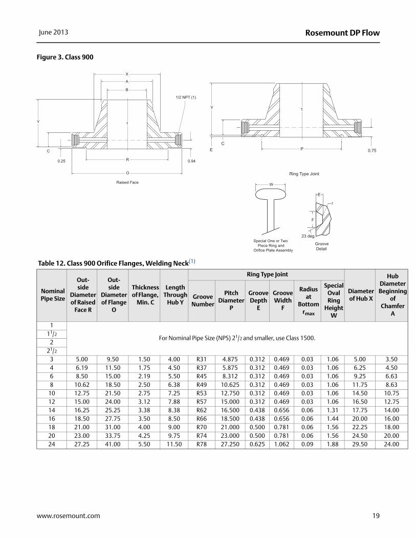
Figure 3. Class 900
Table 12. Class 900 Orifice Flanges, Welding Neck(1)
Nominal Pipe Size
Out-side
Diameter of Raised
Face R
Out-side
Diameter of Flange
O
Thickness of Flange,
Min. C
Length Through
Hub Y
Ring Type Joint
Diameter of Hub X
DiaBeg
Ch
Groove Number
Pitch Diameter
P
Groove Depth
E
Groove Width
F
Radius at
Bottom rmax
Special Oval Ring
Height W
1
For Nominal Pipe Size (NPS) 21/2 and smaller, use Class 1500.11/2
221/2
3 5.00 9.50 1.50 4.00 R31 4.875 0.312 0.469 0.03 1.06 5.00 34 6.19 11.50 1.75 4.50 R37 5.875 0.312 0.469 0.03 1.06 6.25 46 8.50 15.00 2.19 5.50 R45 8.312 0.312 0.469 0.03 1.06 9.25 68 10.62 18.50 2.50 6.38 R49 10.625 0.312 0.469 0.03 1.06 11.75 8
10 12.75 21.50 2.75 7.25 R53 12.750 0.312 0.469 0.03 1.06 14.50 112 15.00 24.00 3.12 7.88 R57 15.000 0.312 0.469 0.03 1.06 16.50 114 16.25 25.25 3.38 8.38 R62 16.500 0.438 0.656 0.06 1.31 17.75 116 18.50 27.75 3.50 8.50 R66 18.500 0.438 0.656 0.06 1.44 20.00 118 21.00 31.00 4.00 9.00 R70 21.000 0.500 0.781 0.06 1.56 22.25 120 23.00 33.75 4.25 9.75 R74 23.000 0.500 0.781 0.06 1.56 24.50 224 27.25 41.00 5.50 11.50 R78 27.250 0.625 1.062 0.09 1.88 29.50 2
X
A
B
1
R
O
Raised Face
Y
C
0.25 0.94
1/2 NPT (1)
1
P
Ring Type Joint
Y
CE 0.75
Special One or Two Piece Ring and Orifice Plate Assembly
W
Groove Detail
E
F
23 deg.
r
19www.rosemount.com

Rosemount DP Flow June 2013
Figure 4. Class 1500
(1)
Nominal Pipe Size
Bore B
Diameter of
Pressure Connection
TT
Drilling Template Length of Stud Bolts(2)(3)
Diameter of Bolt Circle
Number of Holes
Diameter of Holes
Diameter of Bolts
Raised Face
Ring Joint
1
For Nominal Pipe Size (NPS) 21/2 and smaller, use Class 1500.11/2
221/2
3 3/8 7.50 8 7.50 7/8 6.00 6.504 1/2 9.25 8 9.25 11/8 7.00 7.506 1/2 12.50 12 12.50 11/8 7.75 8.258 1/2 15.50 12 15.50 13/8 9.00 9.50
10 1/2 18.50 16 18.50 13/8 9.50 10.0012 1/2 21.00 20 21.00 13/8 10.25 10.7514 1/2 22.00 20 22.00 11/2 11.00 11.5016 1/2 24.25 20 24.25 15/8 11.50 12.0018 1/2 27.00 20 27.00 17/8 13.00 13.7520 1/2 29.50 20 29.50 2 14.00 14.7524 1/2 35.50 20 35.50 21/2 17.50 18.50
(1) All other dimensions are in accordance with ASME B16.5.
(2) In conformance with ASME B16.5, stud bolt lengths do not include point heights.
(3) Bolt lengths for raised face flanges include allowance for orifice and gasket thickness of 0.25 in. for NPS 3-12 and 0.38 in. for NPS 14-24. Bolt lengths for ring type joint flanges include allowance of 0.62 in. for NPS 3-10 and 0.75 in. for NPS 12.
(4) Bore is to be specified by the purchaser.
See
Not
e (4
) .
X
A
B
1
R
O
Raised Face
Y
C
0.25 0.94
1/2 NPT (1)
1
P
Ring Type Joint
Y
CE 0.75
Special One or Two Piece Ring and Orifice Plate Assembly
W
Groove Detail
E
F
23 deg.
r
20 www.rosemount.com

Rosemount DP FlowJune 2013
Hub iameter
eginning of
hamfer A
1.321.902.382.883.504.506.638.63
10.7512.7514.0016.0018.0020.0024.00
Table 13. Class 1500 Orifice Flanges, Welding Neck(1)
Nominal Pipe Size
Outside Diameterof Raised
Face R
Out-sideDiameter
of Flange O
Thickness of Flange,
Min. C
Length Through
Hub Y
Ring Type Joint
Diameter of Hub X
DB
C
Groove Number
Pitch Diameter
P
Groove Depth
E
Groove Width
F
Radius at
Bottom rmax
Special Oval Ring
Height W
1 2.00 5.88 1.50 3.25 R16 2.000 0.250 0.344 0.03 1.00 2.0611/2 2.88 7.00 1.50 3.50 R20 2.688 0.250 0.344 0.03 1.00 2.75
2 3.62 8.50 1.50 4.00 R24 3.750 0.312 0.469 0.03 1.06 4.1221/2 4.12 9.62 1.62 4.12 R27 4.250 0.312 0.469 0.03 1.06 4.88
3 5.00 10.50 1.88 4.62 R35 5.375 0.312 0.469 0.03 1.06 5.254 6.19 12.25 2.12 4.88 R39 6.375 0.312 0.469 0.03 1.06 6.386 8.50 15.50 3.25 6.75 R46 8.312 0.375 0.531 0.06 1.12 9.008 10.62 19.00 3.62 8.38 R50 10.625 0.438 0.656 0.06 1.31 11.50
10 12.75 23.00 4.25 10.00 R54 12.750 0.438 0.656 0.06 1.31 14.5012 15.00 26.50 4.88 11.12 R58 15.000 0.562 0.806 0.06 1.56 17.7514 16.25 29.50 5.25 11.75 R63 16.500 0.625 1.062 0.09 1.75 19.5016 18.50 32.50 5.75 12.25 R67 18.500 0.688 1.188 0.09 2.00 21.7518 21.00 36.00 6.38 12.88 R71 21.000 0.688 1.188 0.09 2.00 23.5020 23.00 38.75 7.00 14.00 R75 23.000 0.688 1.312 0.09 2.12 25.2524 27.25 46.00 8.00 16.00 R79 27.250 0.812 1.438 0.09 2.31 30.00
(1)
Nominal Pipe Size
Bore B
Diameter of
Pressure Connection
TT
Drilling Template Length of Stud Bolts(2)(3)
Diameter of Bolt Circle
Number of Holes
Diameter of Holes
Diameter of Bolts
Raised Face
Ring Joint
1 1/4 4.00 4 1.00 7/8 6.00 6.2511/2 1/4 4.88 4 1.12 1 6.25 6.50
2 1/4 6.50 8 1.00 7/8 6.00 6.5021/2 1/4 7.50 8 1.12 1 6.50 7.00
3 3/8 8.00 8 1.25 11/8 7.25 7.254 1/2 9.50 8 1.38 11/4 8.00 8.506 1/2 12.50 12 1.50 13/8 10.50 11.008 1/2 15.50 12 1.75 15/8 11.75 12.25
10 1/2 19.00 12 2.00 17/8 13.50 14.0012 1/2 22.50 16 2.12 2 15.00 15.7514 1/2 25.00 16 2.38 21/4 16.25 17.5216 1/2 27.75 16 2.62 21/2 17.75 19.0018 1/2 30.50 16 2.88 23/4 19.75 21.0020 1/2 32.75 16 3.12 3 21.50 22.5024 1/2 39.00 16 3.62 31/2 24.50 26.00
(1) All other dimensions are in accordance with ASME B16.5.
(2) Bolt lengths for raised face flanges include allowance for orifice and gasket thickness of 0.25 in. for NPS 1-12 and 0.38 in. for NPS 14-24. Bolt lengths for ring type joint flanges include allowance of 0.62 in. for NPS 1-10, 0.75 in. for NPS 12-18, and 0.88 in. for NPS 20.
(3) In conformance with ASME B16.5, stud bolt lengths do not include point heights.
(4) Bore is to be specified by the purchaser.
See
Not
e (4
) .
21www.rosemount.com

Rosemount DP Flow June 2013
Diameter inning of amfer A
1.321.902.382.883.504.504.508.630.752.75
Figure 5. Class 2500
Table 14. Class 2500 Orifice Flanges, Welding Neck(1)
Nominal Pipe Size
Outside Diameter of Raised
Face R
Outside Diameter of Flange
O
Thickness of
Flange, Min. C
Length Through
Hub Y
Ring Type Joint
Diameter of Hub X
HubBeg
ChGroove
Number
Pitch Diameter
P
Groove Depth E
Groove Width
F
Radius at
Bottom rmax
Special Oval Ring
Height W
1 2.00 6.25 1.50 3.62 R18 2.375 0.250 0.344 0.03 1.00 2.251.5 2.88 8.00 1.75 4.38 R23 3.250 0.312 0.469 0.03 1.06 3.12
2 3.62 9.25 2.00 5.00 R26 4.000 0.312 0.469 0.03 1.06 3.752.5 4.12 10.50 2.25 5.62 R28 4.375 0.375 0.531 0.06 1.19 4.50
3 5.00 12.00 2.62 6.62 R32 5.000 0.375 0.531 0.06 1.19 5.254 6.19 14.00 3.00 7350 R38 6.188 0.438 0.656 0.06 1.31 6.506 8.50 19.00 4.25 10.75 R47 9.000 0.500 0.781 0.06 1.31 6.508 10.62 21.75 5.00 12.50 R51 11.000 0.562 0.906 0.06 1.56 12.00
10 12.75 26.50 6.50 16.50 R55 13.500 0.688 1.188 0.09 1.88 14.75 112 15.00 30.00 7.25 18.25 R60 16.000 0.688 1.312 0.09 2.00 17.38 1
X
A
B
1
R
O
Raised Face
Y
C
0.25 0.94
1/2 NPT (1) 1
P
Ring Type Joint
Y
CE 0.75
Special One or Two Piece Ring and Orifice Plate Assembly
W
Groove Detail
E
F
23 deg.
r
22 www.rosemount.com

Rosemount DP FlowJune 2013
(1)
Nominal Pipe Size
Bore B
Diameter of
Pressure Connection
TT
Drilling Template Length of Stud Bolts(2)(3)
Diameter of Bolt Circle
Number of Holes
Diameter of Holes
Diameter of Bolts
Raised Face
Ring Joint
1
See
Not
e(4)
1/4 4.25 4 1.00 7/8 6.00 6.251.5 1/4 5.75 4 1.25 11/8 7.00 7.50
2 1/4 6.75 8 1.12 1 7.25 7.752.5 1/4 7.75 8 1.25 11/8 8.00 8.50
3 3/8 9.00 8 1.38 11/4 9.00 9.504 1/2 10.75 8 1.62 11/2 10.25 10.756 1/2 14.50 8 2.12 2 13.75 14.508 1/2 17.25 12 2.12 2 15.25 16.00
10 1/2 21.25 12 2.62 21/2 19.25 20.2512 1/2 24.38 12 2.88 23/4 21.25 22.50
(1) All other dimensions are in accordance with ASME B16.5.
(2) Bolt lengths for raised face flanges include allowance for orifice and gasket thickness of 0.25 in. for NPS 1-12 and 0.38 in. for NPS 14-24. Bolt lengths for ring type joint flanges include allowance of 0.62 in. for NPS 1-10, 0.75 in. for NPS 12-18, and 0.88 in. for NPS 20.
(3) In conformance with ASME B16.5, stud bolt lengths do not include point heights.
(4) Bore is to be specified by the purchaser.
23www.rosemount.com

Rosemount DP Flow00813-0900-4485 Rev EC
Product Data SheetJune 2013
Emerson Process ManagementRosemount Inc.8200 Market BoulevardChanhassen, MN 55317 USAT (U.S.) 1-800-999-9307T (International) (952) 906-8888F (952) 906-8889www.rosemount.com
Emerson Process ManagementBlegistrasse 23P.O. Box 1046CH 6341 BaarSwitzerlandT +41 (0) 41 768 6111F +41 (0) 41 768 6300www.rosemount.com
Emerson Process Management Asia Pacific Pte Ltd1 Pandan CrescentSignapore 128461T +65 6777 8211F +65 6777 0947Service Support Hotline: +65 6770 8711Email: [email protected]
Emerson Process Management Latin America1300 Concord Terrace, Suite 400Sunrise Florida 33323 USAT + 1 954 846 5030www.rosemount.com
Standard Terms and Conditions of Sale can be found at www.rosemount.com\terms_of_saleThe Emerson logo is a trade mark and service mark of Emerson Electric Co.Rosemount and the Rosemount logotype are registered trademarks of Rosemount Inc.PlantWeb is a registered trademark of one of the Emerson Process Management group of companies.HART and WirelessHART are registered trademarks of the HART Communication FoundationModbus is a trademark of Modicon, Inc.All other marks are the property of their respective owners.© 2013 Rosemount Inc. All rights reserved.


![[XLS]iancas.orgiancas.org/download/iancas-lm-list.xls · Web viewBINITA NANDA LM-1495 MALABIKA TALUKDAR LM-1496 SNEHA PRABHA MISHRA LM-1497 SANJIBITA DAS LM-1498 SANTOSH KUMAR PARIDA](https://img.dokumen.tips/doc/110x75/5ac8e9fd7f8b9acb688cf503/xls-viewbinita-nanda-lm-1495-malabika-talukdar-lm-1496-sneha-prabha-mishra-lm-1497.jpg)