Embed Size (px)
Citation preview
PRODUCT CATALOGUE
Member of the Honing Beheer Group of Companies
Thermobile Industries B.V.
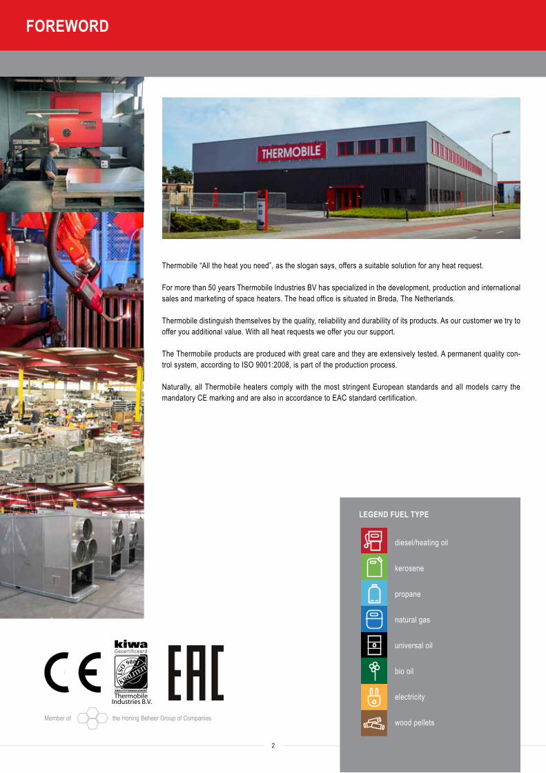
Thermobile “All the heat you need”, as the slogan says, offers a suitable solution for any heat request.
For more than 50 years Thermobile Industries BV has specialized in the development, production and international sales and marketing of space heaters. The head office is situated in Breda, The Netherlands.
Thermobile distinguish themselves by the quality, reliability and durability of its products. As our customer we try to offer you additional value. With all heat requests we offer you our support.
The Thermobile products are produced with great care and they are extensively tested. A permanent quality con-trol system, according to ISO 9001:2008, is part of the production process.
Naturally, all Thermobile heaters comply with the most stringent European standards and all models carry the mandatory CE marking and are also in accordance to EAC standard certification.
LEGEND FUEL TYPE
diesel/heating oil
kerosene
propane
natural gas
universal oil
bio oil
electricity
wood pellets
2
FOREWORD
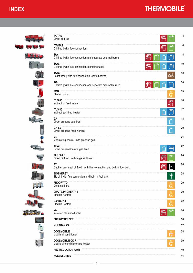
TA/TAS 4Direct oil fired
ITA/ITAS 6Oil fired | with flue connection
IMA 8Oil fired | with flue connection and separate external burner
IMAC 10Oil fired | with flue connection (containerized)
IMAC 12Pellet fired | with flue connection (containerized)
ISA 14Oil fired | with flue connection and separate external burner
TMB 15Electric boiler
ITLS 65 16Indirect oil fired heater
ITLS 80 17Indirect gas fired heater
GA 18Direct propane gas fired
GA EV 20Direct propane fired, vertical
MS 21Modulating control units propane gas
AGA E 22Direct propane/natural gas fired
TAS 800 E 24Direct oil fired | with large air throw
AT 26Cabinet universal oil fired | with flue connection and built-in fuel tank
BIOENERGY 28Bio oil | with flue connection and built-in fuel tank
PRODRY TD 29Dehumidifiers
CH/VTB/PROHEAT 18 30Electric Heaters
BX/TBD 18 32Electric Heaters
VAL 34Infra-red radiant oil fired
ENERGYTENDER 36
MULTITANKS 37
COOLMOBILE 38Mobile airconditioner
COOLMOBILE C/CR 39Mobile air conditioner and heater
RECIRCULATION FANS 40
ACCESSORIES 41
3
INDEX
FUEL TYPE
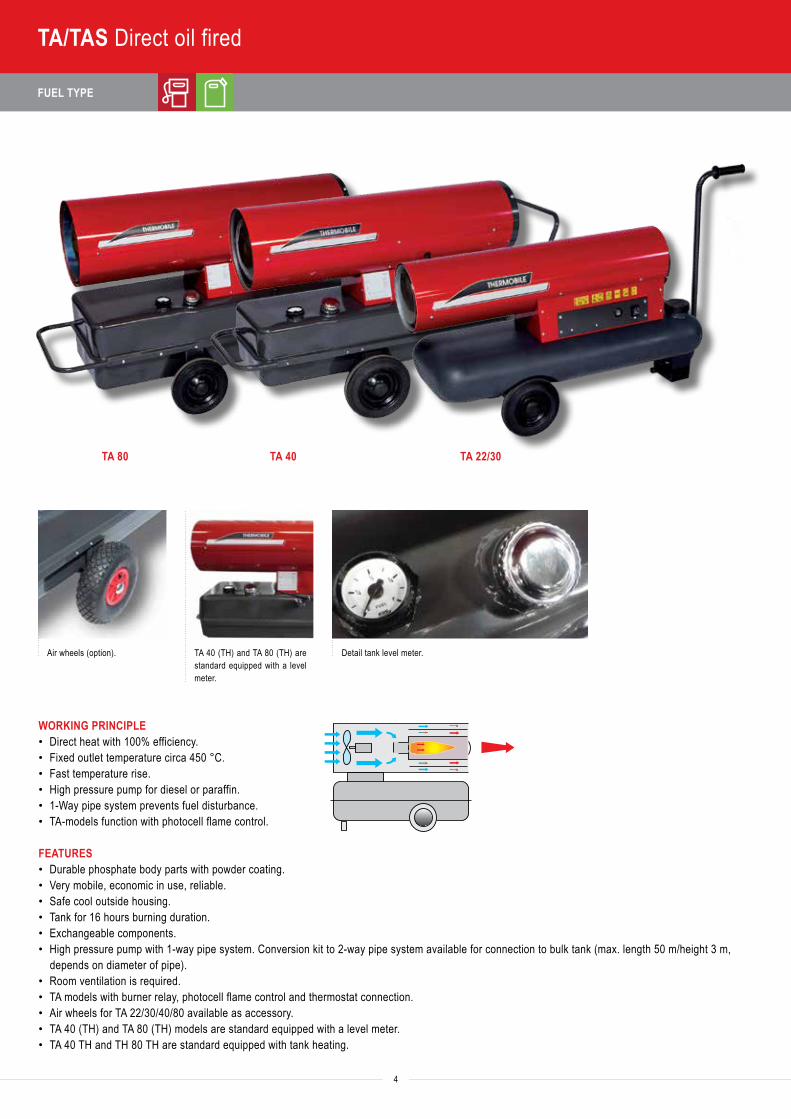
WORKING PRINCIPLE• Direct heat with 100% efficiency.• Fixed outlet temperature circa 450 °C.• Fast temperature rise.• High pressure pump for diesel or paraffin.• 1-Way pipe system prevents fuel disturbance.• TA-models function with photocell flame control.
FEATURES• Durable phosphate body parts with powder coating.• Very mobile, economic in use, reliable.• Safe cool outside housing.• Tank for 16 hours burning duration.• Exchangeable components.• High pressure pump with 1-way pipe system. Conversion kit to 2-way pipe system available for connection to bulk tank (max. length 50 m/height 3 m,
depends on diameter of pipe).• Room ventilation is required.• TA models with burner relay, photocell flame control and thermostat connection.• Air wheels for TA 22/30/40/80 available as accessory.• TA 40 (TH) and TA 80 (TH) models are standard equipped with a level meter.• TA 40 TH and TH 80 TH are standard equipped with tank heating.
Air wheels (option). Detail tank level meter.TA 40 (TH) and TA 80 (TH) are standard equipped with a level meter.
TA 80 TA 40 TA 22/30
Heat
out
put (
Btu/
hr)
Heat
out
put (
kW)
Fuel
con
sum
ptio
n oi
l max
. (l/h
r)He
ated
air
flow
(m3 /h
r)Ta
nk c
apac
ity (l
)
Powe
r con
sum
ptio
n 23
0 V
(AM
PS)
Ther
mos
tat c
onne
ctio
n
4
TA/TAS Direct oil fired
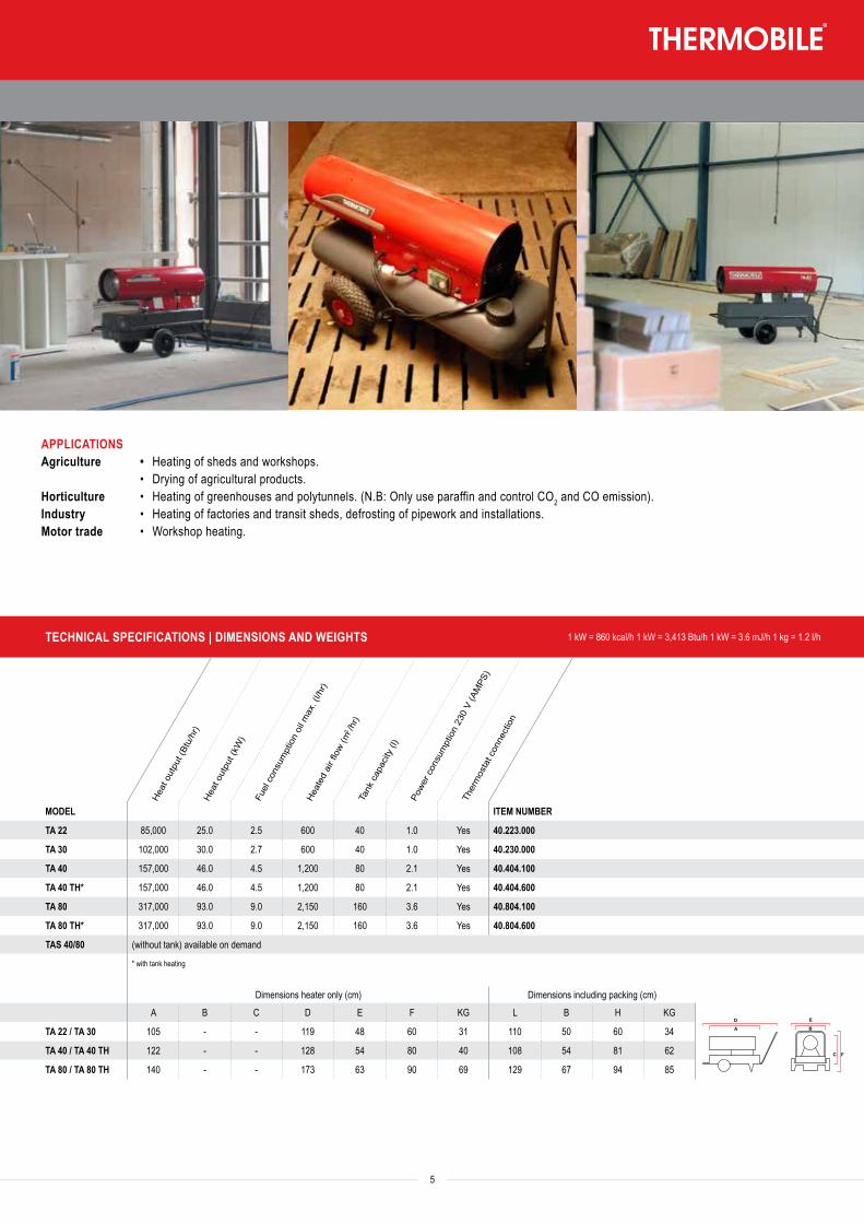
APPLICATIONSAgriculture • Heating of sheds and workshops. • Drying of agricultural products.Horticulture • Heating of greenhouses and polytunnels. (N.B: Only use paraffin and control CO2 and CO emission). Industry • Heating of factories and transit sheds, defrosting of pipework and installations.Motor trade • Workshop heating.
TECHNICAL SPECIFICATIONS | DIMENSIONS AND WEIGHTS 1 kW = 860 kcal/h 1 kW = 3,413 Btu/h 1 kW = 3.6 mJ/h 1 kg = 1.2 l/h
Heat
out
put (
Btu/
hr)
Heat
out
put (
kW)
Fuel
con
sum
ptio
n oi
l max
. (l/h
r)He
ated
air
flow
(m3 /h
r)Ta
nk c
apac
ity (l
)
Powe
r con
sum
ptio
n 23
0 V
(AM
PS)
Ther
mos
tat c
onne
ctio
n
MODEL ITEM NUMBER
TA 22 85,000 25.0 2.5 600 40 1.0 Yes 40.223.000
TA 30 102,000 30.0 2.7 600 40 1.0 Yes 40.230.000
TA 40 157,000 46.0 4.5 1,200 80 2.1 Yes 40.404.100
TA 40 TH* 157,000 46.0 4.5 1,200 80 2.1 Yes 40.404.600
TA 80 317,000 93.0 9.0 2,150 160 3.6 Yes 40.804.100
TA 80 TH* 317,000 93.0 9.0 2,150 160 3.6 Yes 40.804.600
TAS 40/80 (without tank) available on demand
* with tank heating
Dimensions heater only (cm) Dimensions including packing (cm)
A B C D E F KG L B H KG
TA 22 / TA 30 105 - - 119 48 60 31 110 50 60 34
TA 40 / TA 40 TH 122 - - 128 54 80 40 108 54 81 62
TA 80 / TA 80 TH 140 - - 173 63 90 69 129 67 94 85TA
ITA
IMA
IMAC
GAGA EV
AGA ETAS 800 E
ATPRODRY
BioEnergy
BX, CH, VTB, TTV
5
FUEL TYPE
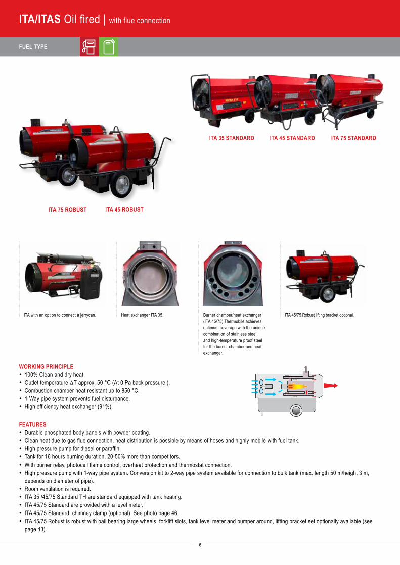
WORKING PRINCIPLE· 100% Clean and dry heat.· Outlet temperature ΔT approx. 50 °C (At 0 Pa back pressure.).· Combustion chamber heat resistant up to 850 °C.· 1-Way pipe system prevents fuel disturbance.· High efficiency heat exchanger (91%).
FEATURES· Durable phosphated body panels with powder coating.· Clean heat due to gas flue connection, heat distribution is possible by means of hoses and highly mobile with fuel tank.· High pressure pump for diesel or paraffin.· Tank for 16 hours burning duration, 20-50% more than competitors.· With burner relay, photocell flame control, overheat protection and thermostat connection.· High pressure pump with 1-way pipe system. Conversion kit to 2-way pipe system available for connection to bulk tank (max. length 50 m/height 3 m,
depends on diameter of pipe).· Room ventilation is required.· ITA 35 /45/75 Standard TH are standard equipped with tank heating.· ITA 45/75 Standard are provided with a level meter.· ITA 45/75 Standard chimney clamp (optional). See photo page 46.· ITA 45/75 Robust is robust with ball bearing large wheels, forklift slots, tank level meter and bumper around, lifting bracket set optionally available (see
page 43).
ITA with an option to connect a jerrycan. Burner chamber/heat exchanger (ITA 45/75) Thermobile achieves optimum coverage with the unique combination of stainless steel and high-temperature proof steel for the burner chamber and heat exchanger.
Heat exchanger ITA 35.
ITA 75 ROBUST ITA 45 ROBUST
ITA 35 STANDARD ITA 45 STANDARD ITA 75 STANDARD
ITA 45/75 Robust lifting bracket optional.
Heat
out
put (
Btu/
hr)
Heat
out
put (
kW)
Fuel
con
sum
ptio
n oi
l max
. (l/h
r)He
ated
air
flow
(m3 /h
r)M
ax. v
entila
tor b
ack
pres
sure
(Pa)
Tank
cap
acity
(l)
Powe
r con
sum
ptio
n 23
0 V
(AM
PS)
Out
let c
one
Ø (m
m)
Flue
con
nect
ion
Ø (m
m)
Ther
mos
tat c
onne
ctio
n
6
ITA/ITAS Oil fired | with flue connection
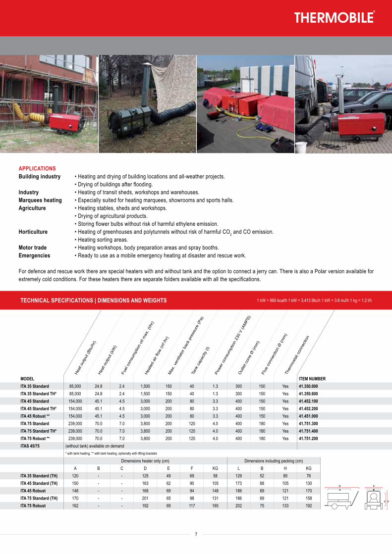
APPLICATIONSBuilding industry • Heating and drying of building locations and all-weather projects. • Drying of buildings after flooding.Industry • Heating of transit sheds, workshops and warehouses.Marquees heating • Especially suited for heating marquees, showrooms and sports halls.Agriculture • Heating stables, sheds and workshops. • Drying of agricultural products. • Storing flower bulbs without risk of harmful ethylene emission.Horticulture • Heating of greenhouses and polytunnels without risk of harmful CO2 and CO emission. • Heating sorting areas.Motor trade • Heating workshops, body preparation areas and spray booths.Emergencies • Ready to use as a mobile emergency heating at disaster and rescue work.
For defence and rescue work there are special heaters with and without tank and the option to connect a jerry can. There is also a Polar version available for extremely cold conditions. For these heaters there are separate folders available with all the specifications.
TECHNICAL SPECIFICATIONS | DIMENSIONS AND WEIGHTS 1 kW = 860 kcal/h 1 kW = 3,413 Btu/h 1 kW = 3.6 mJ/h 1 kg = 1.2 l/h
Heat
out
put (
Btu/
hr)
Heat
out
put (
kW)
Fuel
con
sum
ptio
n oi
l max
. (l/h
r)He
ated
air
flow
(m3 /h
r)M
ax. v
entila
tor b
ack
pres
sure
(Pa)
Tank
cap
acity
(l)
Powe
r con
sum
ptio
n 23
0 V
(AM
PS)
Out
let c
one
Ø (m
m)
Flue
con
nect
ion
Ø (m
m)
Ther
mos
tat c
onne
ctio
n
MODEL ITEM NUMBERITA 35 Standard 85,000 24.8 2.4 1,500 150 40 1.3 300 150 Yes 41.350.000ITA 35 Standard TH* 85,000 24.8 2.4 1,500 150 40 1.3 300 150 Yes 41.350.600ITA 45 Standard 154,000 45.1 4.5 3,000 200 80 3.3 400 150 Yes 41.452.100ITA 45 Standard TH* 154,000 45.1 4.5 3,000 200 80 3.3 400 150 Yes 41.452.200ITA 45 Robust ** 154,000 45.1 4.5 3,000 200 80 3.3 400 150 Yes 41.451.000ITA 75 Standard 239,000 70.0 7.0 3,800 200 120 4.0 400 180 Yes 41.751.300ITA 75 Standard TH* 239,000 70.0 7.0 3,800 200 120 4.0 400 180 Yes 41.751.400ITA 75 Robust ** 239,000 70.0 7.0 3,800 200 120 4.0 400 180 Yes 41.751.200ITAS 45/75 (without tank) available on demand
* with tank heating, ** with tank heating, optionally with lifting brackets
Dimensions heater only (cm) Dimensions including packing (cm)A B C D E F KG L B H KG
ITA 35 Standard (TH) 120 - - 125 49 69 58 129 52 85 76ITA 45 Standard (TH) 150 - - 163 62 90 105 173 68 105 130ITA 45 Robust 148 - - 168 69 94 148 186 69 121 170ITA 75 Standard (TH) 170 - - 201 65 98 131 186 69 121 158ITA 75 Robust 162 - - 192 69 117 165 202 75 133 192
TA
ITA
IMA
IMAC
GAGA EV
AGA ETAS 800 E
ATPRODRY
BioEnergy
BX, CH, VTB, TTV
7
FUEL TYPE
Heat
out
put (
Btu/
hr)
Heat
out
put (
kW)
Fuel
con
sum
ptio
n oi
l max
. (l/h
r)He
ated
air
flow
(m3 /h
r)M
ax. v
entila
tor b
ack
pres
sure
(Pa)
Powe
r con
sum
ptio
nO
utle
t con
e Ø
(mm
)Fl
ue c
onne
ctio
n Ø
(mm
)Th
erm
osta
t con
nect
ion
TECHNICAL SPECIFICATIONS | DIMENSIONS AND WEIGHTS 1 kW = 860 kcal/h 1 kW = 3,413 Btu/h 1 kW = 3.6 mJ/h 1 kg = 1.2 l/h
8
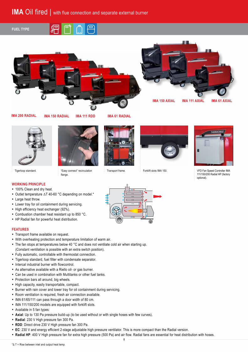
IMA Oil fired | with flue connection and separate external burner
IMA 200 RADIAL IMA 150 RADIAL IMA 111 RDD IMA 61 RADIAL
IMA 150 AXIAL IMA 111 AXIAL IMA 61 AXIAL
Tigerloop standard. “Easy connect” recirculation flange.
Transport frame. Forklift slots IMA 150. VFD Fan Speed Controller IMA 111/150/200 Radial HP (factory optional).
WORKING PRINCIPLE · 100% Clean and dry heat.· Outlet temperature ΔT 40-60 °C depending on model.*· Large heat throw.· Lower tray for oil containment during servicing.· High efficiency heat exchanger (92%).· Combustion chamber heat resistant up to 850 °C.· HP Radial fan for powerful heat distribution.
FEATURES· Transport frame available on request.· With overheating protection and temperature limitation of warm air.· The fan stops at temperatures below 40 °C and does not ventilate cold air when starting up.
(Constant ventilation is possible with an extra switch position).· Fully automatic, controllable with thermostat connection.· Tigerloop standard, fuel filter with condensate separator.· Intercal industrial burner with flowcontrol. · As alternative available with a Riello oil- or gas burner.· Can be used in combination with Multitanks or other fuel tanks.· Protection bars all around, big wheels.· High capacity, easily transportable, compact.· Burner with rain cover and lower tray for oil containment during servicing.· Room ventilation is required, fresh air connection available.· IMA 61/65/111 can pass through a door width of 80 cm.· IMA 111/150/200 models are equipped with forklift slots.· Available in 5 fan types:· Axial: Up to 130 Pa pressure build-up (to be used without or with single hoses with few curves).· Radial: 230 V High pressure fan 300 Pa.· RDD: Direct drive 230 V High pressure fan 300 Pa.· EC: 230 V and energy efficient 2-stage adjustable high pressure ventilator. This is more compact than the Radial version.· Radial HP: 400 V High pressure fan for extra high pressure (500 Pa) and air flow. Radial fans are essential for heat distribution with hoses.
*Δ T = Rise between inlet and output heat temp.

Heat
out
put (
Btu/
hr)
Heat
out
put (
kW)
Fuel
con
sum
ptio
n oi
l max
. (l/h
r)He
ated
air
flow
(m3 /h
r)M
ax. v
entila
tor b
ack
pres
sure
(Pa)
Powe
r con
sum
ptio
nO
utle
t con
e Ø
(mm
)Fl
ue c
onne
ctio
n Ø
(mm
)Th
erm
osta
t con
nect
ion
MODEL ITEM NUMBERIMA 61 AX 222,000 65 6.5 4,000 130 3.3/230 V 400 180 Yes 41.722.800IMA 61 RAD 222,000 65 6.5 4,000 250 6.5/230 V 400 180 Yes 41.722.300IMA 65 EC 222,000 65 6.5 4,400 500 5./230 V 500 180 Yes 41.722.850 IMA 111 AX 375,000 110 10.9 5,800 130 4.4/230 V 500 200 Yes 41.724.800IMA 111 RDD 375,000 110 10.9 8,000 300 15/230 V 500 200 Yes 41.724.710IMA 111 RHP 375,000 110 10.9 10,000 500 7.5/400 V 500 200 Yes 41.724.210IMA 150 AX 512,000 150 14.8 7,400 100 5.7/230 V 500 200 Yes 41.726.800IMA 150 RAD 512,000 150 14.8 9,000 300 15/230 V 500 200 Yes 41.726.650IMA 150 RHP 512,000 150 14.8 11,000 500 9/400 V 500 200 Yes 41.726.000IMA 200 RAD 682,000 200 19.4 10,000 300 15/230 V 600 200 Yes 41.728.650IMA 200 RHP 682,000 200 19.4 13,000 500 10/400 V 600 200 Yes 41.728.010
Dimensions heater only (cm) Dimensions including packing (cm) KGA B C D E F KG L B H 230
IMA 61 AX - - - 162 71 128 210 203 75 145 250IMA 61 RAD - - - 199 71 128 245 203 75 145 275IMA 65 EC - - - 179 71 128 235 203 75 145 260IMA 111 AX - - - 179 78 134 295 180 80 145 325
IMA 111 RDD - - - 223 78 134 350 241 98 172 450
IMA 111 RHP - - - 223 78 134 340 241 98 172 440
IMA 150 AX - - - 200 84 151 324 210 95 172 435
IMA 150 RAD - - - 246 84 151 385 265 95 172 525
IMA 150 RHP - - - 246 84 151 385 265 95 172 525
IMA 200 RAD - - - 271 91 152 425 300 104 172 588
IMA 200 RHP - - - 271 91 152 425 300 104 172 588
TECHNICAL SPECIFICATIONS | DIMENSIONS AND WEIGHTS 1 kW = 860 kcal/h 1 kW = 3,413 Btu/h 1 kW = 3.6 mJ/h 1 kg = 1.2 l/h
TA
ITA
IMA
IMAC
GAGA EV
AGA ETAS 800 E
ATPRODRY
BioEnergy
BX, CH, VTB, TTV
9
APPLICATIONSBuilding industry • Heating and drying of building sites and all-weather projects. • Drying of buildings after flooding.Industry • Heating of transit sheds and workshops.Marquees heating • IMA models are especially suited for heating marquees, showrooms and sports halls.Agriculture • Heating of sheds and storage areas. • Drying of agricultural products. • Storing bulbs without the risk of harmful ethylene emission.Horticulture • Heating of greenhouses and polytunnels without the risk of harmful CO2 and CO emission.
FUEL TYPE
Heat
out
put (
Btu/
hr)
Heat
out
put (
kW)
Fuel
con
sum
ptio
n oi
l max
. (l/h
r)He
ated
air
flow
(m3 /h
r)
Max
. ven
tilato
r bac
k pr
essu
re (P
a)Po
wer c
onsu
mpt
ion
400
V (A
MPS
)O
utle
t con
e Ø
(mm
)
Flue
con
nect
ion
Ø (m
m)
Ther
mos
tat c
onne
ctio
n
10
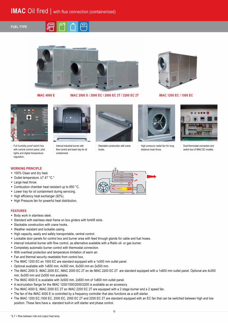
IMAC Oil fired | with flue connection (containerized)
IMAC 4000 E IMAC 2000 S / 2000 EC / 2000 EC 2T / 2200 EC 2T
Full humidity proof switch box with central control panel, pilot lights and digital temperature regulation.
Intercal industrial burner with flow control and lower tray for oil containment.
Stackable construction with crane hooks.
High pressure radial fan for long distance heat throw.
Dual thermostat connection and switch box of IMAC EC models.
WORKING PRINCIPLE· 100% Clean and dry heat.· Outlet temperature ΔT 47 °C.*· Large heat throw.· Combustion chamber heat resistant up to 850 °C.· Lower tray for oil containment during servicing.· High efficiency heat exchanger (92%).· High Pressure fan for powerful heat distribution.
FEATURES· Body work in stainless steel.· Standard with stainless steel frame on box girders with forklift slots.· Stackable construction with crane hooks.· Weather resistant and lockable casing.· High capacity, easily and safely transportable, central control.· Lockable door panels for control box and burner area with feed through glands for cable and fuel hoses.· Intercal industrial burner with flow control, as alternative available with a Riello oil- or gas burner.· Completely automatic burner control with thermostat connection.· With overheat protection and temperature limitation of warm air.· Fan and thermal security resettable from control box.· The IMAC 1200 EC en 1500 EC are standard equipped with a 1x500 mm outlet panel.• Optional available with 1x600 mm, 4x300 mm, 6x300 mm en 2x500 mm.· The IMAC 2000 S, IMAC 2000 EC, IMAC 2000 EC 2T en de IMAC 2200 EC 2T are standard equipped with a 1x600 mm outlet panel. Optional are 4x300
mm, 6x300 mm and 2x500 mm available.· The IMAC 4000 E is available with 3x500 mm, 2x600 mm of 1x800 mm outlet panel.· A recirculation flange for the IMAC 1200/1500/2000/2200 is available as an accessory.· The IMAC 4000 E, IMAC 2000 EC 2T en IMAC 2200 EC 2T are equipped with a 2 stage burner and a 2 speed fan. · The fan of the IMAC 4000 E is controlled by a frequency controller that also functions as a soft starter.· The IMAC 1200 EC,1500 EC, 2000 EC, 2000 EC 2T and 2200 EC 2T are standard equipped with an EC fan that can be switched between high and low
position. These fans have a standard built-in soft starter and phase control.
*Δ T = Rise between inlet and output heat temp.
IMAC 1200 EC / 1500 EC
TECHNICAL SPECIFICATIONS | DIMENSIONS AND WEIGHTS 1 kW = 860 kcal/h 1 kW = 3,413 Btu/h 1 kW = 3.6 mJ/h w1 kg = 1.2 l/h
Heat
out
put (
Btu/
hr)
Heat
out
put (
kW)
Fuel
con
sum
ptio
n oi
l max
. (l/h
r)He
ated
air
flow
(m3 /h
r)
Max
. ven
tilato
r bac
k pr
essu
re (P
a)Po
wer c
onsu
mpt
ion
400
V (A
MPS
)O
utle
t con
e Ø
(mm
)
Flue
con
nect
ion
Ø (m
m)
Ther
mos
tat c
onne
ctio
n
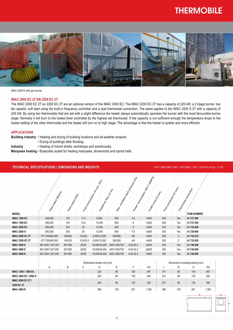
MODEL ITEM NUMBERIMAC 1200 EC 409,000 120 11.4 8,500 500 3.5 1x500 200 Yes 41.727.000IMAC 1500 EC 495,000 145 13.6 10,000 600 6 1x500 200 Yes 41.727.500IMAC 2000 EC 683,000 200 20 12,000 600 6 1x600 200 Yes 41.732.000IMAC 2000 S 683,000 200 20 12,000 600 7.5 1x600 200 Yes 41.729.600IMAC 2000 EC 2T 477,700/683,000 140/200 13.9/20 9,000/12,000 350/600 4/6 1x600 200 2 41.732.010IMAC 2200 EC 2T 477,700/683,000 140/220 13.9/20.5 9,000/12,000 350/550 4/6 1x600 200 2 41.732.020IMAC 4000 E 891,000/1,307,000 261/383 26/38 18,000/24,000 400/1,000/700 9-20-20.3 3x500 300 Yes 41.740.500IMAC 4000 E 891,000/1,307,000 261/383 26/38 18,000/24,000 400/1,000/700 9-20-20.3 2x600 300 Yes 41.740.600IMAC 4000 E 891,000/1,307,000 261/383 26/38 18,000/24,000 400/1,000/700 9-20-20.3 1x800 300 Yes 41.740.800
Dimensions heater only (cm) Dimensions including packing (cm)A B C D E F KG L B H KG
IMAC 1200 / 1500 EC - - - 220 80 135 467 211 80 135 467IMAC 2000 EC / 2000 S - - - 240 80 135 545 231 80 135 545IMAC 2000 EC 2T / 2200 EC 2T
- - - 240 80 135 550 231 80 135 550
IMAC 4000 E - - - 385 120 201 1.300 385 120 201 1.300
TA
ITA
IMA
IMAC
GAGA EV
AGA ETAS 800 E
ATPRODRY
BioEnergy
BX, CH, VTB, TTV
11
IMAC 2000 EC 2T EN 2200 EC 2TThe IMAC 2000 EC 2T en 2200 EC 2T are an optional version of the IMAC 2000 EC. The IMAC 2200 EC 2T has a capacity of 220 kW, a 2 stage burner, two fan speeds, soft start using the built-in frequency controller and a dual thermostat connection. The same applies to the IMAC 2000 S 2T with a capacity of 200 kW. By using two thermostats that are set with a slight difference the heater always automatically operates the burner with the most favourable burner stage. Normally it will burn to the lowest level controlled by the highest set thermostat. If the capacity is not sufficient enough the temperature drops to the lowest setting of the other thermostat and the heater will turn on to high stage. The advantage is that the heater is quieter and more efficient.
APPLICATIONSBuilding industry • Heating and drying of building locations and all-weather projects. • Drying of buildings after flooding.Industry • Heating of transit sheds, workshops and warehouses.Marquees heating • Especially suited for heating marquees, showrooms and sports halls.
IMAC 2000 E with gas burner.
Heat
out
put (
Btu/
hr)
Heat
out
put (
kW)
Fuel
con
sum
ptio
n pe
llets
max
. (kg
/hr)
Heat
ed a
ir flo
w (m
3 /hr)
Max
. ven
tilato
r bac
k pr
essu
re (P
a)
Powe
r con
sum
ptio
n 40
0 V
(AM
PS)
Out
let c
one
Ø (m
m)
Flue
con
nect
ion
Ø (m
m)
Ther
mos
tat c
onne
ctio
n
12
FUEL TYPE
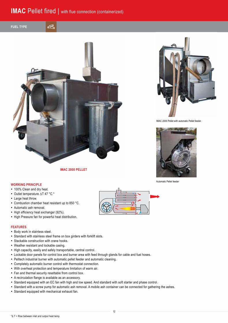
IMAC Pellet fired | with flue connection (containerized)
WORKING PRINCIPLE· 100% Clean and dry heat.· Outlet temperature ΔT 47 °C.*· Large heat throw.· Combustion chamber heat resistant up to 850 °C.· Automatic ash removal.· High efficiency heat exchanger (92%).· High Pressure fan for powerful heat distribution.
FEATURES· Body work in stainless steel.· Standard with stainless steel frame on box girders with forklift slots.· Stackable construction with crane hooks.· Weather resistant and lockable casing.· High capacity, easily and safely transportable, central control.· Lockable door panels for control box and burner area with feed through glands for cable and fuel hoses.· Pelltech industrial burner with automatic pellet feeder and automatic cleaning.· Completely automatic burner control with thermostat connection.· With overheat protection and temperature limitation of warm air.· Fan and thermal security resettable from control box.· A recirculation flange is available as an accessory.· Standard equipped with an EC fan with high and low speed. And standard with soft starter and phase control.· Standard with a screw pump for automatic ash removal. A mobile ash container can be connected for gathering the ashes.· Standard equipped with mechanical exhaust fan.
*Δ T = Rise between inlet and output heat temp.
IMAC 2000 PELLET
IMAC 2000 Pellet with automatic Pellet feeder.
Automatic Pellet feeder
TECHNICAL SPECIFICATIONS | DIMENSIONS AND WEIGHTS 1 kW = 860 kcal/h 1 kW = 3,413 Btu/h 1 kW = 3.6 mJ/h 1 kg = 1.2 l/h
Heat
out
put (
Btu/
hr)
Heat
out
put (
kW)
Fuel
con
sum
ptio
n pe
llets
max
. (kg
/hr)
Heat
ed a
ir flo
w (m
3 /hr)
Max
. ven
tilato
r bac
k pr
essu
re (P
a)
Powe
r con
sum
ptio
n 40
0 V
(AM
PS)
Out
let c
one
Ø (m
m)
Flue
con
nect
ion
Ø (m
m)
Ther
mos
tat c
onne
ctio
n
MODEL ITEM NUMBERIMAC 2000 Pellet 615,000 180 33 13 600 6.5 1 x 500 200 Yes 41.731.000Kliko 41.731.44010 ft container pellet 41.731.410Supply unit 2 x auger 41.731.450
Dimensions heater only (cm)A B C KG
IMAC 2000 Pellet 216 80 134 550
13
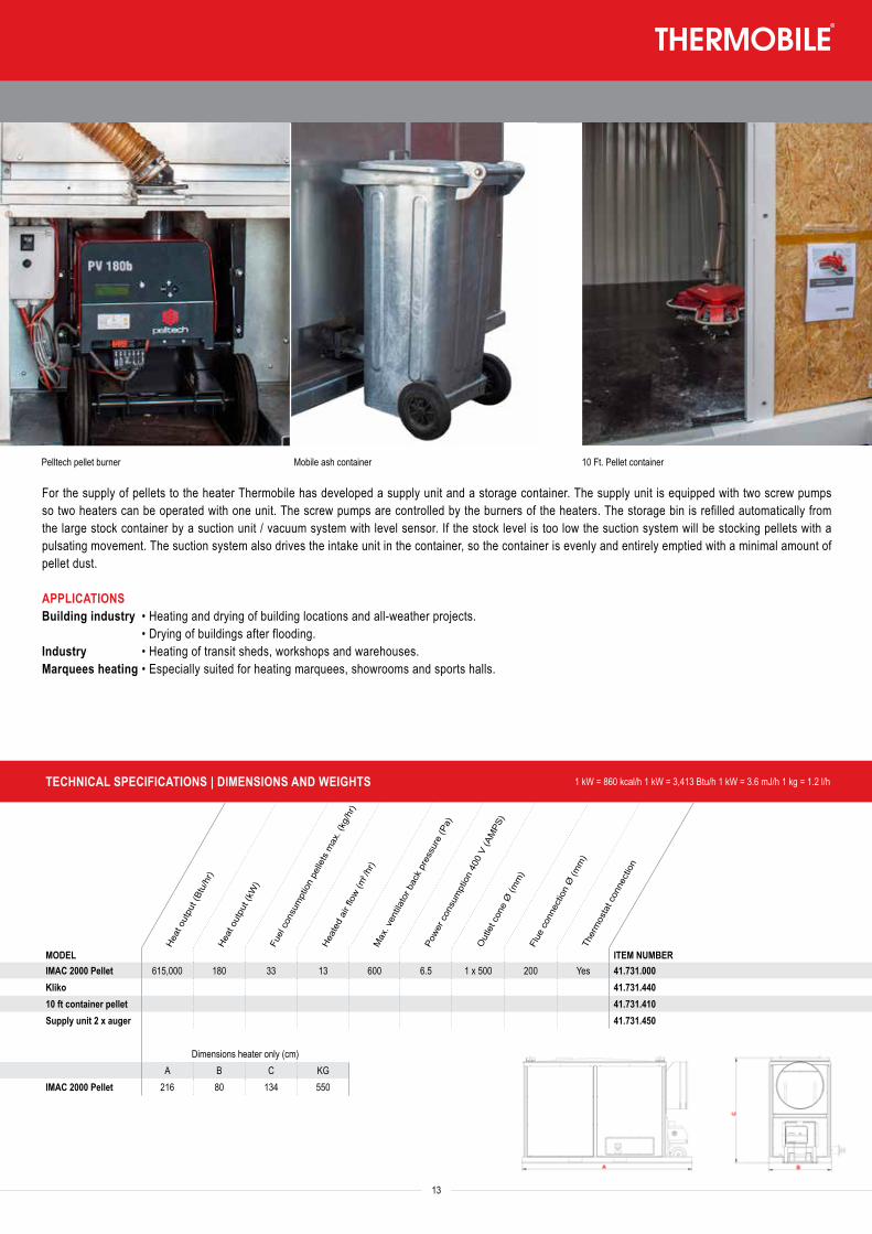
For the supply of pellets to the heater Thermobile has developed a supply unit and a storage container. The supply unit is equipped with two screw pumps so two heaters can be operated with one unit. The screw pumps are controlled by the burners of the heaters. The storage bin is refilled automatically from the large stock container by a suction unit / vacuum system with level sensor. If the stock level is too low the suction system will be stocking pellets with a pulsating movement. The suction system also drives the intake unit in the container, so the container is evenly and entirely emptied with a minimal amount of pellet dust.
APPLICATIONSBuilding industry • Heating and drying of building locations and all-weather projects. • Drying of buildings after flooding.Industry • Heating of transit sheds, workshops and warehouses.Marquees heating • Especially suited for heating marquees, showrooms and sports halls.
10 Ft. Pellet containerPelltech pellet burner Mobile ash container
FUEL TYPE
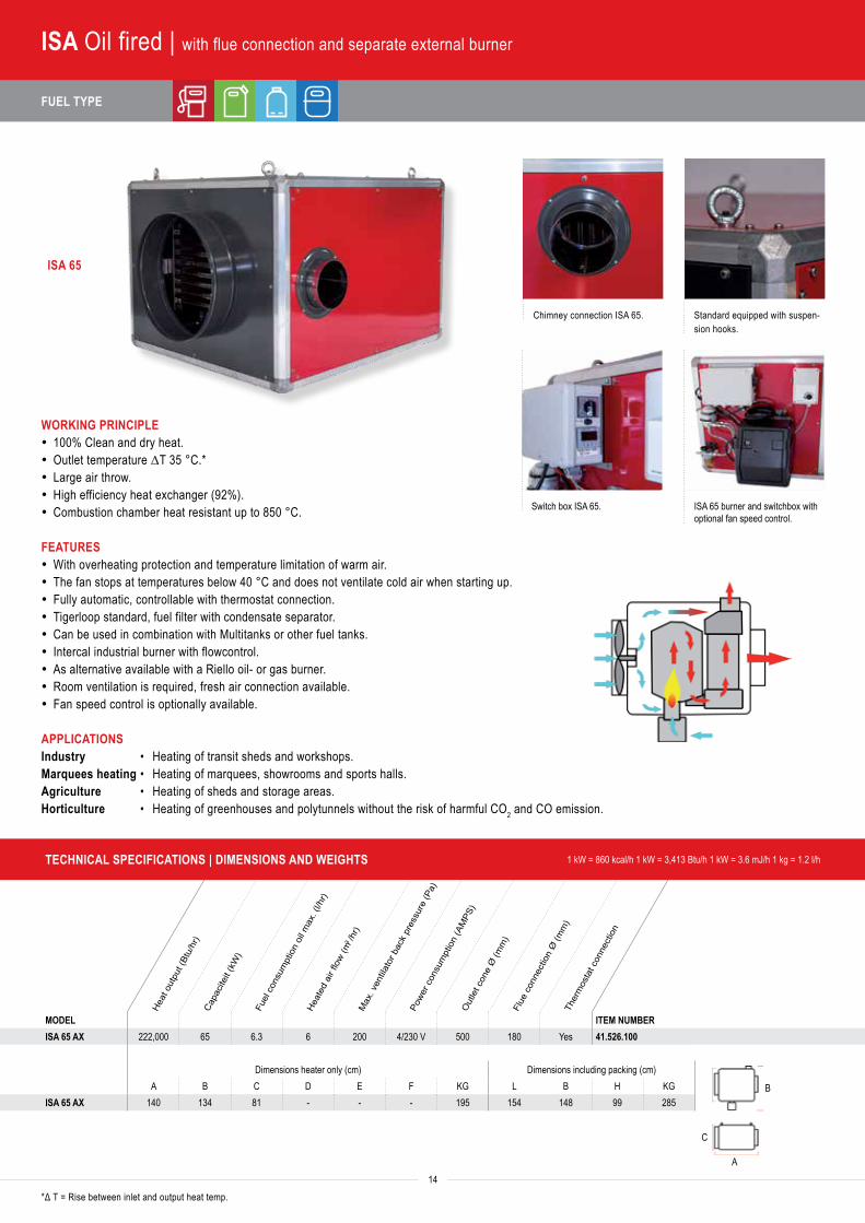
WORKING PRINCIPLE· 100% Clean and dry heat.· Outlet temperature ΔT 35 °C.*· Large air throw.· High efficiency heat exchanger (92%).· Combustion chamber heat resistant up to 850 °C.
FEATURES· With overheating protection and temperature limitation of warm air.· The fan stops at temperatures below 40 °C and does not ventilate cold air when starting up.· Fully automatic, controllable with thermostat connection.· Tigerloop standard, fuel filter with condensate separator.· Can be used in combination with Multitanks or other fuel tanks.· Intercal industrial burner with flowcontrol.· As alternative available with a Riello oil- or gas burner.· Room ventilation is required, fresh air connection available.· Fan speed control is optionally available.
APPLICATIONSIndustry • Heating of transit sheds and workshops.Marquees heating • Heating of marquees, showrooms and sports halls.Agriculture • Heating of sheds and storage areas.Horticulture • Heating of greenhouses and polytunnels without the risk of harmful CO2 and CO emission.
ISA 65
Chimney connection ISA 65. Standard equipped with suspen-sion hooks.
Switch box ISA 65. ISA 65 burner and switchbox with optional fan speed control.
14
ISA Oil fired | with flue connection and separate external burner
*Δ T = Rise between inlet and output heat temp.
Heat
out
put (
Btu/
hr)
Capa
citei
t (kW
)
Fuel
con
sum
ptio
n oi
l max
. (l/h
r)He
ated
air
flow
(m3 /h
r)M
ax. v
entila
tor b
ack
pres
sure
(Pa)
Powe
r con
sum
ptio
n (A
MPS
)O
utle
t con
e Ø
(mm
)Fl
ue c
onne
ctio
n Ø
(mm
)Th
erm
osta
t con
nect
ion
MODEL ITEM NUMBERISA 65 AX 222,000 65 6.3 6 200 4/230 V 500 180 Yes 41.526.100
Dimensions heater only (cm) Dimensions including packing (cm)A B C D E F KG L B H KG
ISA 65 AX 140 134 81 - - - 195 154 148 99 285
TECHNICAL SPECIFICATIONS | DIMENSIONS AND WEIGHTS 1 kW = 860 kcal/h 1 kW = 3,413 Btu/h 1 kW = 3.6 mJ/h 1 kg = 1.2 l/h
B
C
A
Max
. hea
t out
put (
Btu)
Powe
r con
sum
ptio
n (A
MPS
)Po
wer r
ates
(AM
PS)
Wat
er d
ispla
cem
ent (
m3 /h
r)Te
mpe
ratu
re ra
nge
(°C)
Ope
ratin
g pr
essu
re (b
ar)
Safe
ty v
alve
(bar
)
Heat
ing
conn
ectio
nsDr
ying
prog
ram
con
cret
e
FUEL TYPE
15
Heat
out
put (
Btu/
hr)
Capa
citei
t (kW
)
Fuel
con
sum
ptio
n oi
l max
. (l/h
r)He
ated
air
flow
(m3 /h
r)M
ax. v
entila
tor b
ack
pres
sure
(Pa)
Powe
r con
sum
ptio
n (A
MPS
)O
utle
t con
e Ø
(mm
)Fl
ue c
onne
ctio
n Ø
(mm
)Th
erm
osta
t con
nect
ion
MODEL ITEM NUMBERISA 65 AX 222,000 65 6.3 6 200 4/230 V 500 180 Yes 41.526.100
Dimensions heater only (cm) Dimensions including packing (cm)A B C D E F KG L B H KG
ISA 65 AX 140 134 81 - - - 195 154 148 99 285
TECHNICAL SPECIFICATIONS | DIMENSIONS AND WEIGHTS 1 kW = 860 kcal/h 1 kW = 3,413 Btu/h 1 kW = 3.6 mJ/h 1 kg = 1.2 l/h
Max
. hea
t out
put (
Btu)
Powe
r con
sum
ptio
n (A
MPS
)Po
wer r
ates
(AM
PS)
Wat
er d
ispla
cem
ent (
m3 /h
r)Te
mpe
ratu
re ra
nge
(°C)
Ope
ratin
g pr
essu
re (b
ar)
Safe
ty v
alve
(bar
)
Heat
ing
conn
ectio
nsDr
ying
prog
ram
con
cret
e
MODEL ITEM NUMBERTMB 19 65,000 19 3/11/19 3 20 - 80 1.5 - 2 3 DN25 - 19.019.000TMB 19F 65,000 19 3/11/19 3 20 - 80 1.5 - 2 3 DN25 yes 19.019.100TMB 20 68,000 20 20 3 20 - 80 1.5 - 2 3 DN25 - 19.020.000TMB 20F 68,000 20 20 3 20 - 80 1.5 - 2 3 DN25 yes 19.020.100TMB 40 136,000 40 8/16/40 3 20 - 80 1.5 - 2 3 DN25 - 19.040.000TMB 40F 136,000 40 8/16/40 3 20 - 80 1.5 - 2 3 DN25 yes 19.040.100
Dimensions boiler only (cm) Dimensions including packing (cm)A B C D E F KG L B H KG
TMB 19 (F) 600 550 122 - - - 57 - - - -TMB 20 (F) 600 550 122 - - - 57 - - - -TMB 40 (F) 670 530 126 - - - 65 - - - -
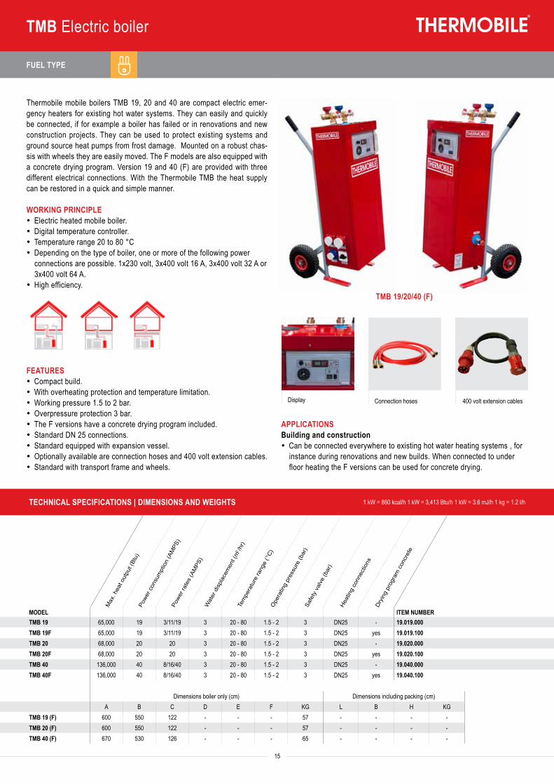
Display Connection hoses 400 volt extension cables
TMB Electric boiler
TMB 19/20/40 (F)
Thermobile mobile boilers TMB 19, 20 and 40 are compact electric emer-gency heaters for existing hot water systems. They can easily and quickly be connected, if for example a boiler has failed or in renovations and new construction projects. They can be used to protect existing systems and ground source heat pumps from frost damage. Mounted on a robust chas-sis with wheels they are easily moved. The F models are also equipped with a concrete drying program. Version 19 and 40 (F) are provided with three different electrical connections. With the Thermobile TMB the heat supply can be restored in a quick and simple manner.
WORKING PRINCIPLE· Electric heated mobile boiler.· Digital temperature controller.· Temperature range 20 to 80 °C· Depending on the type of boiler, one or more of the following power
connections are possible. 1x230 volt, 3x400 volt 16 A, 3x400 volt 32 A or 3x400 volt 64 A.
· High efficiency.
FEATURES· Compact build.· With overheating protection and temperature limitation.· Working pressure 1.5 to 2 bar.· Overpressure protection 3 bar.· The F versions have a concrete drying program included.· Standard DN 25 connections.· Standard equipped with expansion vessel.· Optionally available are connection hoses and 400 volt extension cables.· Standard with transport frame and wheels.
APPLICATIONSBuilding and construction · Can be connected everywhere to existing hot water heating systems , for
instance during renovations and new builds. When connected to under floor heating the F versions can be used for concrete drying.
FUEL TYPE
TECHNICAL SPECIFICATIONS | DIMENSIONS AND WEIGHTS 1 kW = 860 kcal/h 1 kW = 3,413 Btu/h 1 kW = 3.6 mJ/h 1 kg = 1.2 l/h
Heat
out
put (
Btu/
hr)
Heat
out
put (
kW/h
r)
Fuel
con
sum
ptio
n (l/
h)
Heat
ed a
ir flo
w (m
3 )
Powe
r con
sum
ptio
n 23
0 V
(AM
PS)
Flue
con
nect
ion
Ø (m
m)
Ther
mos
tat c
onne
ctio
n
MODEL ITEM NUMBERITLS 65 222,000 65 6.5 7,500 7 180 Yes 41.526.300
Dimensions heater only (cm)L W H KG
ITLS 65 99 118 166 260
Heat
out
put (
Btu/
hr)
Heat
out
put (
kW/h
r)
Gas
con
sum
ptio
n m
ax. (
m3 /h
) G20
/25
Gas
con
sum
ptio
n m
ax. (
kg/h
) G31
Air t
hrow
(m)
Heat
ed a
ir flo
w (m
3 )
Powe
r con
sum
ptio
n 23
0 V
(AM
PS)
Ther
mos
tat c
onne
ctio
n
16
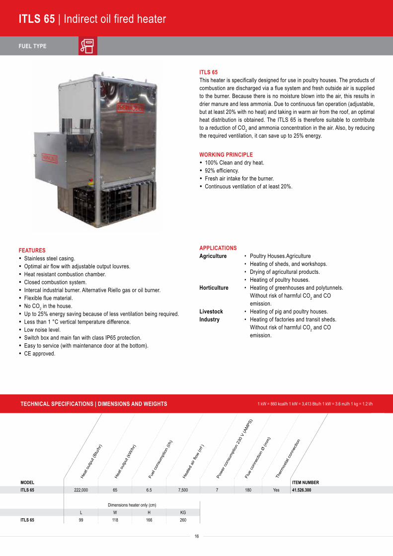
ITLS 65 | Indirect oil fired heater
FEATURES· Stainless steel casing.· Optimal air flow with adjustable output louvres.· Heat resistant combustion chamber.· Closed combustion system.· Intercal industrial burner. Alternative Riello gas or oil burner.· Flexible flue material.· No CO2 in the house. · Up to 25% energy saving because of less ventilation being required.· Less than 1 °C vertical temperature difference. · Low noise level.· Switch box and main fan with class IP65 protection.· Easy to service (with maintenance door at the bottom).· CE approved.
APPLICATIONSAgriculture • Poultry Houses.Agriculture • Heating of sheds, and workshops. • Drying of agricultural products. • Heating of poultry houses.Horticulture • Heating of greenhouses and polytunnels.
Without risk of harmful CO2 and CO emission.
Livestock • Heating of pig and poultry houses.Industry • Heating of factories and transit sheds. Without risk of harmful CO2 and CO
emission.
ITLS 65This heater is specifically designed for use in poultry houses. The products of combustion are discharged via a flue system and fresh outside air is supplied to the burner. Because there is no moisture blown into the air, this results in drier manure and less ammonia. Due to continuous fan operation (adjustable, but at least 20% with no heat) and taking in warm air from the roof, an optimal heat distribution is obtained. The ITLS 65 is therefore suitable to contribute to a reduction of CO2 and ammonia concentration in the air. Also, by reducing the required ventilation, it can save up to 25% energy.
WORKING PRINCIPLE· 100% Clean and dry heat.· 92% efficiency.· Fresh air intake for the burner.· Continuous ventilation of at least 20%.
FUEL TYPE
TECHNICAL SPECIFICATIONS | DIMENSIONS AND WEIGHTS 1 kW = 860 kcal/h 1 kW = 3,413 Btu/h 1 kW = 3.6 mJ/h 1 kg = 1.2 l/h
Heat
out
put (
Btu/
hr)
Heat
out
put (
kW/h
r)
Fuel
con
sum
ptio
n (l/
h)
Heat
ed a
ir flo
w (m
3 )
Powe
r con
sum
ptio
n 23
0 V
(AM
PS)
Flue
con
nect
ion
Ø (m
m)
Ther
mos
tat c
onne
ctio
n
MODEL ITEM NUMBERITLS 65 222,000 65 6.5 7,500 7 180 Yes 41.526.300
Dimensions heater only (cm)L W H KG
ITLS 65 99 118 166 260
TECHNICAL SPECIFICATIONS | DIMENSIONS AND WEIGHTS 1 kW = 860 kcal/h 1 kW = 3,413 Btu/h 1 kW = 3.6 mJ/h 1 kg = 1.2 l/h
Heat
out
put (
Btu/
hr)
Heat
out
put (
kW/h
r)
Gas
con
sum
ptio
n m
ax. (
m3 /h
) G20
/25
Gas
con
sum
ptio
n m
ax. (
kg/h
) G31
Air t
hrow
(m)
Heat
ed a
ir flo
w (m
3 )
Powe
r con
sum
ptio
n 23
0 V
(AM
PS)
Ther
mos
tat c
onne
ctio
n
MODEL ITEM NUMBERITLS 80 273,000 80 8,1/9,0 6,0 45 6,000 4,1 Yes 41.800.000
Dimensions heater only (cm)L W H KG
ITLS 80 179 89 105 (118*) 200* Hight including fan.
17
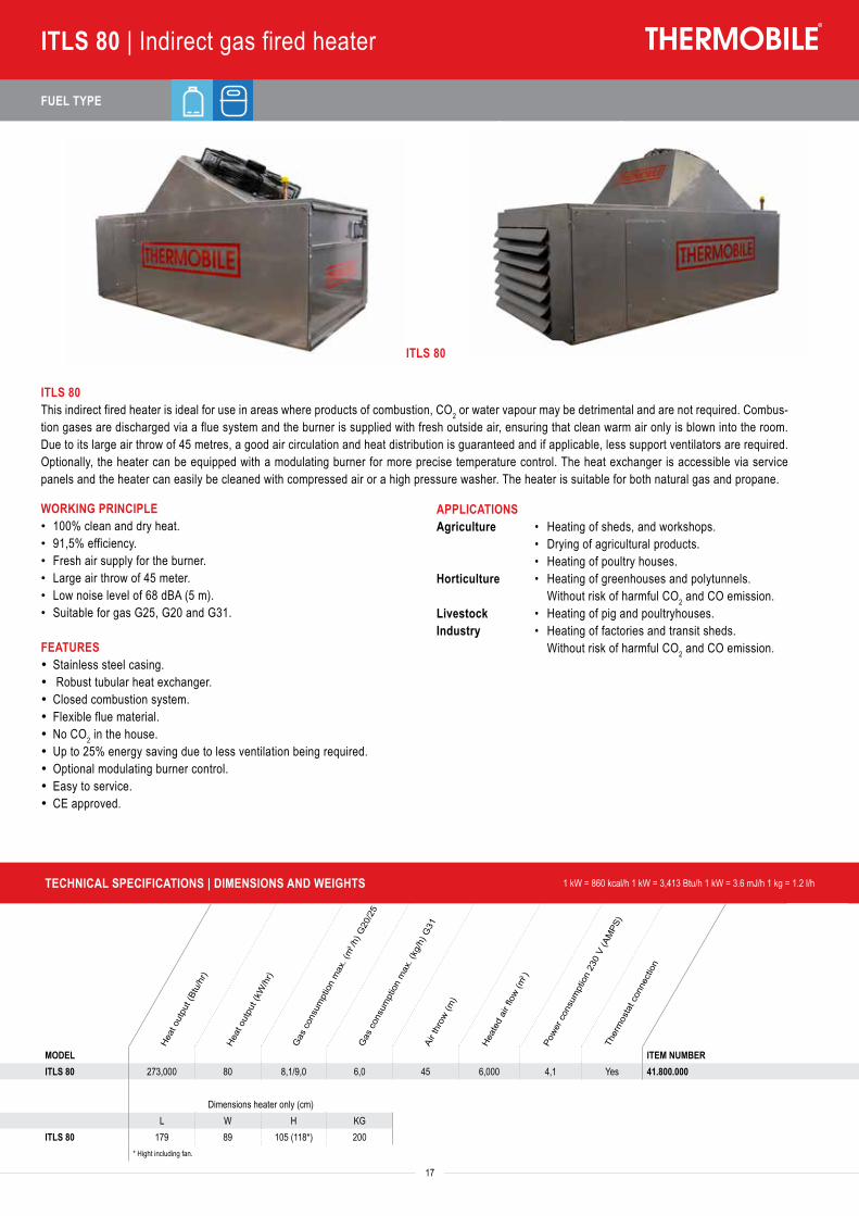
ITLS 80 | Indirect gas fired heater
ITLS 80This indirect fired heater is ideal for use in areas where products of combustion, CO2 or water vapour may be detrimental and are not required. Combus-tion gases are discharged via a flue system and the burner is supplied with fresh outside air, ensuring that clean warm air only is blown into the room. Due to its large air throw of 45 metres, a good air circulation and heat distribution is guaranteed and if applicable, less support ventilators are required. Optionally, the heater can be equipped with a modulating burner for more precise temperature control. The heat exchanger is accessible via service panels and the heater can easily be cleaned with compressed air or a high pressure washer. The heater is suitable for both natural gas and propane.
WORKING PRINCIPLE• 100% clean and dry heat.• 91,5% efficiency.• Fresh air supply for the burner.• Large air throw of 45 meter.• Low noise level of 68 dBA (5 m).• Suitable for gas G25, G20 and G31.
FEATURES· Stainless steel casing.· Robust tubular heat exchanger.· Closed combustion system.· Flexible flue material.· No CO2 in the house. · Up to 25% energy saving due to less ventilation being required.· Optional modulating burner control.· Easy to service.· CE approved.
APPLICATIONSAgriculture • Heating of sheds, and workshops. • Drying of agricultural products. • Heating of poultry houses.Horticulture • Heating of greenhouses and polytunnels.
Without risk of harmful CO2 and CO emission.Livestock • Heating of pig and poultryhouses. Industry • Heating of factories and transit sheds. Without risk of harmful CO2 and CO emission.
ITLS 80
FUEL TYPE
Heat
out
put (
Btu/
hr)
Heat
out
put (
kW)
Fuel
con
sum
ptio
n ga
s (k
g/hr
)
Heat
ed a
ir flo
w (m
3 /hr)
Powe
r con
sum
ptio
n 23
0 V
(AM
PS)
Gas
con
nect
ion
Ø (i
nch)
Gas
pre
ssur
e on
hea
ter (
bar)
Ther
mos
tat c
onne
ctio
n
18
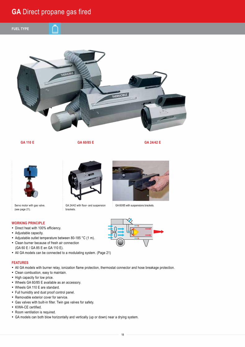
GA Direct propane gas fired
GA 110 E GA 60/85 E GA 24/42 E
Servo motor with gas valve. (see page 21).
GA 24/42 with floor- and suspension brackets.
GA 60/85 with suspensions brackets.
WORKING PRINCIPLE· Direct heat with 100% efficiency.· Adjustable capacity.· Adjustable outlet temperature between 80-185 °C (1 m).· Clean burner because of fresh air connection
(GA 60 E / GA 85 E en GA 110 E).· All GA models can be connected to a modulating system. (Page 21)
FEATURES· All GA models with burner relay, ionization flame protection, thermostat connector and hose breakage protection.· Clean combustion, easy to maintain.· High capacity for low price.· Wheels GA 60/85 E available as an accessory.· Wheels GA 110 E are standard.· Full humidity and dust proof control panel.· Removable exterior cover for service.· Gas valves with built-in filter. Twin gas valves for safety.· KIWA-CE certified.· Room ventilation is required.· GA models can both blow horizontally and vertically (up or down) near a drying system.
TECHNICAL SPECIFICATIONS | DIMENSIONS AND WEIGHTS 1 kW = 860 kcal/h 1 kW = 3,413 Btu/h 1 kW = 3.6 mJ/h 1 kg = 1.2 l/h
Heat
out
put (
Btu/
hr)
Heat
out
put (
kW)
Fuel
con
sum
ptio
n ga
s (k
g/hr
)
Heat
ed a
ir flo
w (m
3 /hr)
Powe
r con
sum
ptio
n 23
0 V
(AM
PS)
Gas
con
nect
ion
Ø (i
nch)
Gas
pre
ssur
e on
hea
ter (
bar)
Ther
mos
tat c
onne
ctio
n
MODEL Min. Max. Min. Max. Min. Max. ITEM NUMBERGA 24 E 54,500 106,000 16 31 1,1 2,1 760 0,60 1/2 0,4-1,5 Yes 40.274.000GA 42 E 61,500 150,000 18 44 1.4 3.2 760 0.60 1/2 0.4-1.5 Yes 40.277.000GA 60 E* 92,000 218,000 27 64 1.9 4.6 2,400 0.64 1/2 0.4-2.0 Yes 40.707.005GA 85 E* 133,000 317,000 39 93 2.8 6.7 2,400 0.64 1/2 0.4-2.0 Yes 40.707.002GA 110 E 184,000 444,000 54 130 3.9 9.3 4,000 2.20 1/2 0.4-2.0 Yes 40.710.005
* Standard without wheels, for wheel sets see Accessories
Dimensions heater only (cm) Dimensions including packing (cm)A B C D E F KG L B H KG
GA 24 E 58 37 45 - - - 16 70 40 50 17GA 42 E 58 37 45 - - - 16 70 40 50 17
GA 60 E 100 46 47 109 47 58 36 110 50 60 41
GA 85 E 100 46 47 109 47 58 36 110 50 60 41
GA 110 E 118 53 60 118 63 77 55 129 67 94 71
TA
ITA
IMA
IMAC
GAGA EV
AGA ETAS 800 E
ATPRODRY
BioEnergy
BX, CH, VTB, TTV
19
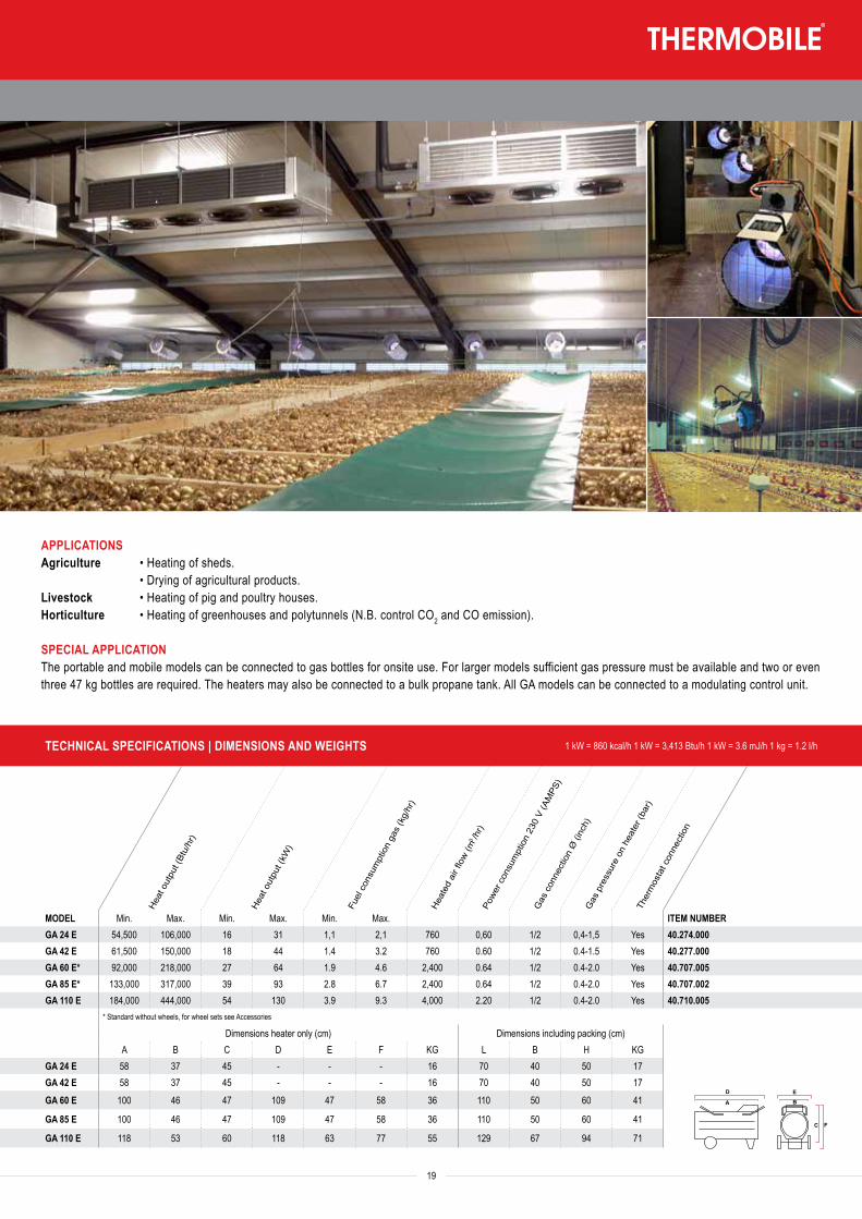
APPLICATIONSAgriculture • Heating of sheds. • Drying of agricultural products.Livestock • Heating of pig and poultry houses.Horticulture • Heating of greenhouses and polytunnels (N.B. control CO2 and CO emission).
SPECIAL APPLICATIONThe portable and mobile models can be connected to gas bottles for onsite use. For larger models sufficient gas pressure must be available and two or even three 47 kg bottles are required. The heaters may also be connected to a bulk propane tank. All GA models can be connected to a modulating control unit.
FUEL TYPE
TECHNICAL SPECIFICATIONS | DIMENSIONS AND WEIGHTS 1 kW = 860 kcal/h 1 kW = 3,413 Btu/h 1 kW = 3.6 mJ/h 1 kg = 1.2 l/h
Heat
out
put (
Btu/
hr)
Heat
out
put (
kW)
Fuel
con
sum
ptio
n ga
s (k
g/hr
)
Heat
ed a
ir flo
w (m
3 /hr)
Powe
r con
sum
ptio
n 23
0 V
(AM
PS)
Gas
con
nect
ion
Ø (i
nch)
Gas
pre
ssur
e on
hea
ter (
bar)
Ther
mos
tat c
onne
ctio
n
MODEL Min. Max. Min. Max. Min. Max. ITEM NUMBERGA 24 EV 54,500 106,000 16 31 1.1 2.1 760 0.60 1/2 0.4-1.5 Yes 40.274.000GA 42 EV 61,500 150,000 18.0 44 1.4 3.2 760 0.60 1/2 0.4-1.5 Yes 40.277.000GA 60 EV* 92,000 218,000 27.0 64 1.9 4.6 2,400 0.64 1/2 0.4-2.0 Yes 40.707.005GA 85 EV* 133,000 317,000 39.0 93 2.8 6.7 2,400 0.64 1/2 0.4-2.0 Yes 40.707.002GA 110 EV 184,000 444,000 54.0 130 3.9 9.3 4,000 2.20 1/2 0.4-2.0 Yes 40.710.005
* Standard without wheels, for wheel sets see Accessories
Dimensions heater only (cm) Dimensions including packing (cm)A B C D E F KG L B H KG
GA 24 EV 58 37 45 - - - 16 70 40 50 17GA 42 EV 58 37 45 - - - 16 70 40 50 17
GA 60 EV* 100 46 47 109 47 58 36 110 50 60 41
GA 85 EV* 100 46 47 109 47 58 36 110 50 60 41
GA 110 EV 118 53 60 118 63 77 55 129 67 94 71
TA
ITA
IMA
IMAC
GAGA EV
AGA ETAS 800 E
ATPRODRY
BioEnergy
BX, CH, VTB, TTV
20
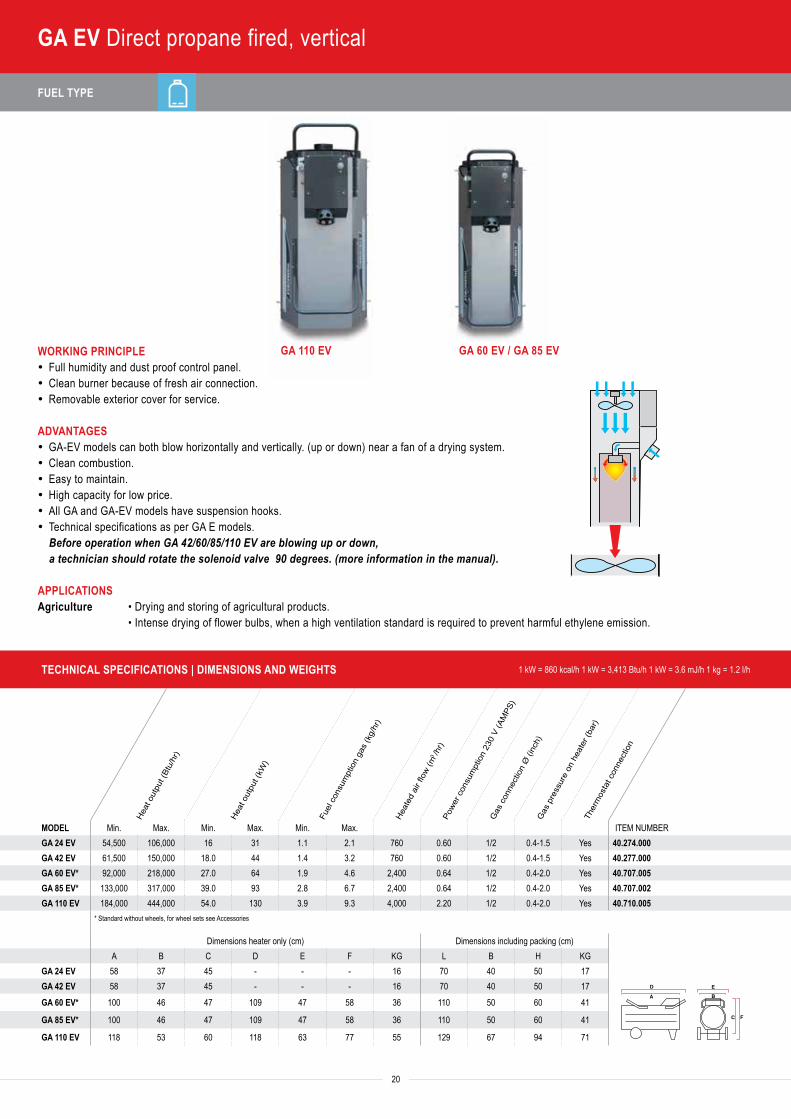
GA EV Direct propane fired, vertical
GA 110 EV GA 60 EV / GA 85 EVWORKING PRINCIPLE· Full humidity and dust proof control panel.· Clean burner because of fresh air connection.· Removable exterior cover for service.
ADVANTAGES· GA-EV models can both blow horizontally and vertically. (up or down) near a fan of a drying system.· Clean combustion.· Easy to maintain.· High capacity for low price.· All GA and GA-EV models have suspension hooks.· Technical specifications as per GA E models.
Before operation when GA 42/60/85/110 EV are blowing up or down, a technician should rotate the solenoid valve 90 degrees. (more information in the manual).
APPLICATIONSAgriculture • Drying and storing of agricultural products. • Intense drying of flower bulbs, when a high ventilation standard is required to prevent harmful ethylene emission.
Heat
out
put (
Btu/
hr)
Heat
out
put (
kW)
Fuel
con
sum
ptio
n ga
s (k
g/hr
)
Heat
ed a
ir flo
w (m
3 /hr)
Powe
r con
sum
ptio
n 23
0 V
(AM
PS)
Gas
con
nect
ion
Ø (i
nch)
Gas
pre
ssur
e on
hea
ter (
bar)
Ther
mos
tat c
onne
ctio
n
MODEL Min. Max. Min. Max. Min. Max. ITEM NUMBERGA 24 EV 54,500 106,000 16 31 1.1 2.1 760 0.60 1/2 0.4-1.5 Yes 40.274.000GA 42 EV 61,500 150,000 18.0 44 1.4 3.2 760 0.60 1/2 0.4-1.5 Yes 40.277.000GA 60 EV* 92,000 218,000 27.0 64 1.9 4.6 2,400 0.64 1/2 0.4-2.0 Yes 40.707.005GA 85 EV* 133,000 317,000 39.0 93 2.8 6.7 2,400 0.64 1/2 0.4-2.0 Yes 40.707.002GA 110 EV 184,000 444,000 54.0 130 3.9 9.3 4,000 2.20 1/2 0.4-2.0 Yes 40.710.005
* Standard without wheels, for wheel sets see Accessories
Dimensions heater only (cm) Dimensions including packing (cm)A B C D E F KG L B H KG
GA 24 EV 58 37 45 - - - 16 70 40 50 17GA 42 EV 58 37 45 - - - 16 70 40 50 17
GA 60 EV* 100 46 47 109 47 58 36 110 50 60 41
GA 85 EV* 100 46 47 109 47 58 36 110 50 60 41
GA 110 EV 118 53 60 118 63 77 55 129 67 94 71
21
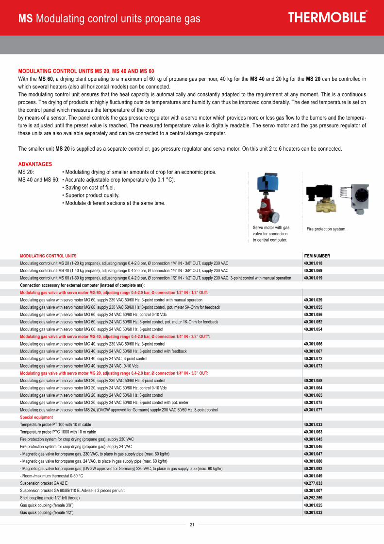
MS Modulating control units propane gas
MODULATING CONTROL UNITS MS 20, MS 40 AND MS 60With the MS 60, a drying plant operating to a maximum of 60 kg of propane gas per hour, 40 kg for the MS 40 and 20 kg for the MS 20 can be controlled in which several heaters (also all horizontal models) can be connected.The modulating control unit ensures that the heat capacity is automatically and constantly adapted to the requirement at any moment. This is a continuous process. The drying of products at highly fluctuating outside temperatures and humidity can thus be improved considerably. The desired temperature is set on the control panel which measures the temperature of the cropby means of a sensor. The panel controls the gas pressure regulator with a servo motor which provides more or less gas flow to the burners and the tempera-ture is adjusted until the preset value is reached. The measured temperature value is digitally readable. The servo motor and the gas pressure regulator of these units are also available separately and can be connected to a central storage computer.
The smaller unit MS 20 is supplied as a separate controller, gas pressure regulator and servo motor. On this unit 2 to 6 heaters can be connected.
ADVANTAGESMS 20: • Modulating drying of smaller amounts of crop for an economic price.MS 40 and MS 60: • Accurate adjustable crop temperature (to 0,1 °C). • Saving on cost of fuel. • Superior product quality. • Modulate different sections at the same time.
Servo motor with gas valve for connection to central computer.
Fire protection system.
MODULATING CONTROL UNITS ITEM NUMBERModulating control unit MS 20 (1-20 kg propane), adjusting range 0.4-2.0 bar, Ø connection 1/4” IN - 3/8” OUT, supply 230 VAC 40.301.018Modulating control unit MS 40 (1-40 kg propane), adjusting range 0.4-2.0 bar, Ø connection 1/4” IN - 3/8” OUT, supply 230 VAC 40.301.069Modulating control unit MS 60 (1-60 kg propane), adjusting range 0.4-2.0 bar, Ø connection 1/2” IN - 1/2” OUT, supply 230 VAC, 3-point control with manual operation 40.301.019Connection accessory for external computer (instead of complete ms):Modulating gas valve with servo motor MG 60, adjusting range 0.4-2.0 bar, Ø connection 1/2” IN - 1/2" OUT:Modulating gas valve with servo motor MG 60, supply 230 VAC 50/60 Hz, 3-point control with manual operation 40.301.029Modulating gas valve with servo motor MG 60, supply 230 VAC 50/60 Hz, 3-point control, pot. meter 5K-Ohm for feedback 40.301.055Modulating gas valve with servo motor MG 60, supply 24 VAC 50/60 Hz, control 0-10 Vdc 40.301.056Modulating gas valve with servo motor MG 60, supply 24 VAC 50/60 Hz, 3-point control, pot. meter 1K-Ohm for feedback 40.301.052Modulating gas valve with servo motor MG 60, supply 24 VAC 50/60 Hz, 3-point control 40.301.054Modulating gas valve with servo motor MG 40, adjusting range 0.4-2.0 bar, Ø connection 1/4” IN - 3/8” OUT”:Modulating gas valve with servo motor MG 40, supply 230 VAC 50/60 Hz, 3-point control 40.301.066Modulating gas valve with servo motor MG 40, supply 24 VAC 50/60 Hz, 3-point control with feedback 40.301.067Modulating gas valve with servo motor MG 40, supply 24 VAC, 3-point control 40.301.072Modulating gas valve with servo motor MG 40, supply 24 VAC, 0-10 Vdc 40.301.073Modulating gas valve with servo motor MG 20, adjusting range 0.4-2.0 bar, Ø connection 1/4” IN - 3/8” OUT:Modulating gas valve with servo motor MG 20, supply 230 VAC 50/60 Hz, 3-point control 40.301.058Modulating gas valve with servo motor MG 20, supply 24 VAC 50/60 Hz, control 0-10 Vdc 40.301.064Modulating gas valve with servo motor MG 20, supply 24 VAC 50/60 Hz, 3-point control 40.301.065Modulating gas valve with servo motor MG 20, supply 24 VAC 50/60 Hz, 3-point control with pot. meter 40.301.075Modulating gas valve with servo motor MS 24, (DVGW approved for Germany) supply 230 VAC 50/60 Hz, 3-point control 40.301.077Special equipmentTemperature probe PT 100 with 10 m cable 40.301.033Temperature probe PTC 1000 with 10 m cable 40.301.063Fire protection system for crop drying (propane gas), supply 230 VAC 40.301.045Fire protection system for crop drying (propane gas), supply 24 VAC 40.301.046- Magnetic gas valve for propane gas, 230 VAC, to place in gas supply pipe (max. 60 kg/hr) 40.301.047- Magnetic gas valve for propane gas, 24 VAC, to place in gas supply pipe (max. 60 kg/hr) 40.301.080- Magnetic gas valve for propane gas, (DVGW approved for Germany) 230 VAC, to place in gas supply pipe (max. 60 kg/hr) 40.301.093- Room-/maximum thermostat 0-50 °C 40.301.049Suspension bracket GA 42 E 40.277.033Suspension bracket GA 60/85/110 E. Advise is 2 pieces per unit. 40.301.007Shell coupling (male 1/2” left thread) 40.252.259Gas quick coupling (female 3/8”) 40.301.025Gas quick coupling (female 1/2”) 40.301.032
FUEL TYPE
Heat
out
put m
ax. (
Btu/
hr)
Heat
out
put m
ax. (
kW)
Gas
con
sum
tion
max
. (m
3 /hr),
prop
ane
kg/h
r
Heat
ed a
ir flo
w (m
3 /hr)
Powe
r con
sum
ptio
n 23
0 V
(AM
PS)
Air t
hrow
(m)
Gas
con
nect
ion
Ø (I
nch)
Ther
mos
tat c
onne
ctio
n
22
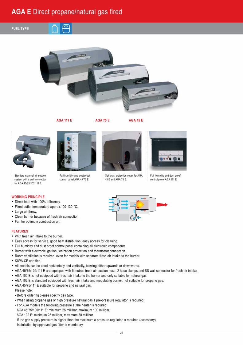
AGA E Direct propane/natural gas fired
AGA 111 E AGA 75 E AGA 45 E
Standard external air suction system with a wall connector for AGA 45/75/102/111 E.
Full humidity and dust proof control panel AGA 45/75 E.
Optional: protection cover for AGA 45 E and AGA 75 E.
Full humidity and dust proof control panel AGA 111 E.
WORKING PRINCIPLE· Direct heat with 100% efficiency.· Fixed outlet temperature approx.100-130 °C.· Large air throw.· Clean burner because of fresh air connection.· Fan for optimum combustion air.
FEATURES· With fresh air intake to the burner.· Easy access for service, good heat distribution, easy access for cleaning.· Full humidity and dust proof control panel containing all electronic components.· Burner with electronic ignition, ionization protection and thermostat connection.· Room ventilation is required, even for models with separate fresh air intake to the burner.· KIWA-CE certified.· All models can be used horizontally and vertically, blowing either upwards or downwards.· AGA 45/75/102/111 E are equipped with 5 metres fresh air suction hose, 2 hose clamps and SS wall connector for fresh air intake.· AGA 100 E is not equipped with fresh air intake to the burner and only suitable for natural gas· AGA 102 E is standard equipped with fresh air intake and modulating burner, not suitable for propane gas.· AGA 45/75/111 E suitable for propane and natural gas.
Please note: - Before ordering please specify gas type. - When using propane gas or high pressure natural gas a pre-pressure regulator is required. - For AGA models the following pressure at the heater is required: AGA 45/75/100/111 E: minimum 25 millibar, maximum 100 millibar. AGA 102 E: minimum 25 millibar, maximum 50 millibar. - If the gas supply pressure is higher than the maximum a pressure regulator is required (accessory). - Installation by approved gas fitter is mandatory.
TECHNICAL SPECIFICATIONS | DIMENSIONS AND WEIGHTS 1 kW = 860 kcal/h 1 kW = 3,413 Btu/h 1 kW = 3.6 mJ/h 1 kg = 1.2 l/h
Heat
out
put m
ax. (
Btu/
hr)
Heat
out
put m
ax. (
kW)
Gas
con
sum
tion
max
. (m
3 /hr),
prop
ane
kg/h
r
Heat
ed a
ir flo
w (m
3 /hr)
Powe
r con
sum
ptio
n 23
0 V
(AM
PS)
Air t
hrow
(m)
Gas
con
nect
ion
Ø (I
nch)
Ther
mos
tat c
onne
ctio
n
MODEL Gas 25* Gas 20 Propane ITEM NUMBERAGA 45 E 154,000 45 5.0 4.0 3.2 2,500 1.0 15 1/2 Yes 40.745.200AGA 75 E 256,000 75 8.3 7.1 5.4 4,500 1.9 25 1/2 Yes 40.775.200AGA 100 E** 358,000 105 11.2 9.0 7.5 7,000 4.8 40 1/2 Yes 40.720.070AGA 102 E** 358,000 105 6.0-13.9 4.3-11.2 - 7,000 5.5 40 1/2 Yes 40.722.100AGA 111 E 358,000 105 11.2 9.0 7.5 7,000 5.3 40 1/2 Yes 40.731.050
* Gas 25 is used in The Netherlands, in most areas of France and in some areas of Belgium.
** Available on request
Dimensions heater only (cm) Dimensions including packing (cm)A B C D E F KG L B H KG
AGA 45 E 106 - 40 68 - - 37 113 84 60 52
AGA 75 E 110 - 52 81 - - 52 113 84 70 67
AGA 100 E 138 60 85 - - - 70 155 75 101 110
AGA 102 E 138 - 85 70 - - 86 155 75 101 105
AGA 111 E 138 - 85 57 - - 84 155 75 101 108
ANCILLARIES ITEM NUMBERPre-pressure regulator 40.720.063Fire protection system for crop drying (natural gas), supply 230 V (24 V execution available optionally), consisting of:• magnetic gas valve for natural gas, to place in gas supply pipe (execution depending on amount of gas and diameter of pipe) 40.301.078• room/maximum thermostat 0/60 °C, to place in drying installation 40.301.049Protection cover for gas unit AGA 45 E and AGA 75 E 40.745.098Modular regulator for AGA 102 E: RE-THA-6 40.722.018Connecting module 0-10 Volt, for connection of the AGA 102 E to an external computer 40.722.019
TA
ITA
IMA
IMAC
GAGA EV
AGA ETAS 800 E
ATPRODRY
BioEnergy
BX, CH, VTB, TTV
23
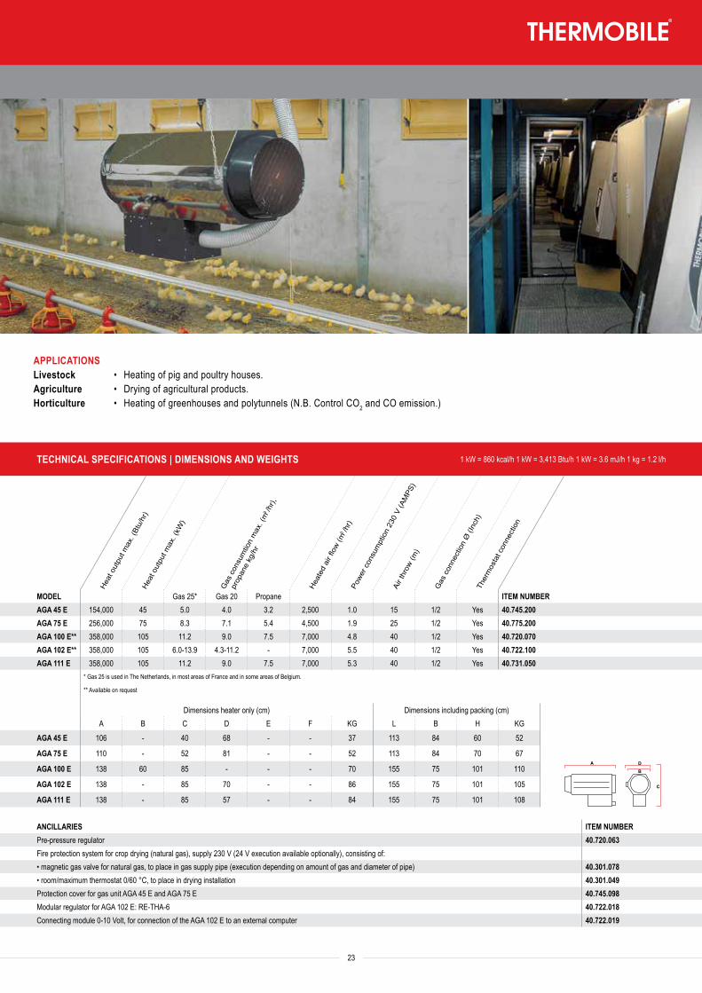
APPLICATIONSLivestock • Heating of pig and poultry houses.Agriculture • Drying of agricultural products.Horticulture • Heating of greenhouses and polytunnels (N.B. Control CO2 and CO emission.)
FUEL TYPE
Heat
out
put (
Btu/
hr)
Heat
out
put (
kW)
Fuel
con
sum
ptio
n oi
l max
. (l/h
r)He
ated
air
flow
(m3 /h
r)Po
wer c
onsu
mpt
ion
230
V (A
MPS
)
Air t
hrow
(m)
Ther
mos
tat c
onne
ctio
n
24
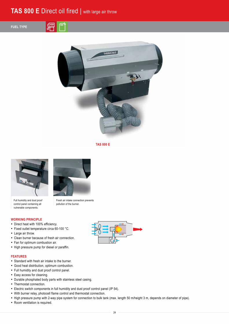
TAS 800 E Direct oil fired | with large air throw
TAS 800 E
Full humidity and dust proof control panel containing all vulnerable components.
Fresh air intake connection prevents pollution of the burner.
WORKING PRINCIPLE· Direct heat with 100% efficiency.· Fixed outlet temperature circa 60-100 °C.· Large air throw.· Clean burner because of fresh air connection.· Fan for optimum combustion air.· High pressure pump for diesel or paraffin.
FEATURES· Standard with fresh air intake to the burner.· Good heat distribution, optimum combustion.· Full humidity and dust proof control panel.· Easy access for cleaning.· Durable phosphated body parts with stainless steel casing.· Thermostat connection.· Electric switch components in full humidity and dust proof control panel (IP 54).· With burner relay, photocell flame control and thermostat connection.· High pressure pump with 2-way pipe system for connection to bulk tank (max. length 50 m/height 3 m, depends on diameter of pipe).· Room ventilation is required.
TECHNICAL SPECIFICATIONS | DIMENSIONS AND WEIGHTS 1 kW = 860 kcal/h 1 kW = 3,413 Btu/h 1 kW = 3.6 mJ/h 1 kg = 1.2 l/h
Heat
out
put (
Btu/
hr)
Heat
out
put (
kW)
Fuel
con
sum
ptio
n oi
l max
. (l/h
r)He
ated
air
flow
(m3 /h
r)Po
wer c
onsu
mpt
ion
230
V (A
MPS
)
Air t
hrow
(m)
Ther
mos
tat c
onne
ctio
n
MODEL ITEM NUMBERTAS 800 E 324,000 95 9.5 7,000 4.6 40 Yes 40.467.000
Dimensions heater only (cm) Dimensions including packing (cm)A B C D E F KG L B H KG
TAS 800 E 152 - 85 58 - - 81 154 74 101 90
TA
ITA
IMA
IMAC
GAGA EV
AGA ETAS 800 E
ATPRODRY
BioEnergy
BX, CH, VTB, TTV
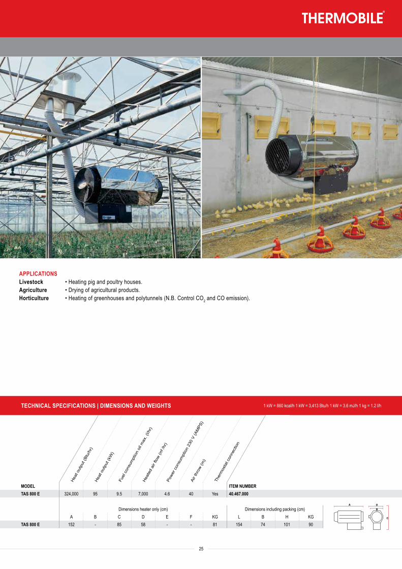
25
APPLICATIONSLivestock • Heating pig and poultry houses.Agriculture • Drying of agricultural products.Horticulture • Heating of greenhouses and polytunnels (N.B. Control CO2 and CO emission).
FUEL TYPE
26
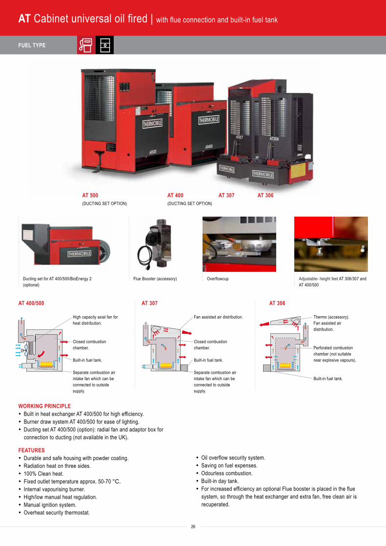
AT Cabinet universal oil fired | with flue connection and built-in fuel tank
AT 500(DUCTING SET OPTION)
AT 400(DUCTING SET OPTION)
AT 307 AT 306
Ducting set for AT 400/500/BioEnergy 2(optional)
WORKING PRINCIPLE· Built in heat exchanger AT 400/500 for high efficiency.· Burner draw system AT 400/500 for ease of lighting.· Ducting set AT 400/500 (option): radial fan and adaptor box for
connection to ducting (not available in the UK).
· Oil overflow security system.· Saving on fuel expenses.· Odourless combustion.· Built-in day tank.· For increased efficiency an optional Flue booster is placed in the flue
system, so through the heat exchanger and extra fan, free clean air is recuperated.
High capacity axial fan forheat distribution.
Closed combustionchamber.
Built-in fuel tank.
Separate combustion airintake fan which can beconnected to outsidesupply.
Fan assisted air distribution.
Closed combustionchamber.
Built-in fuel tank.
Separate combustion airintake fan which can beconnected to outsidesupply.
Thermo (accessory).Fan assisted airdistribution.
Perforated combustionchamber (not suitablenear explosive vapours).
Built-in fuel tank.
AT 400/500 AT 307 AT 306
FEATURES· Durable and safe housing with powder coating.· Radiation heat on three sides.· 100% Clean heat.· Fixed outlet temperature approx. 50-70 °C.· Internal vapourising burner.· High/low manual heat regulation.· Manual ignition system.· Overheat security thermostat.
Flue Booster (accessory) Overflowcup Adjustable- height feet AT 306/307 and AT 400/500
Heat
out
put (
Btu/
hr)
Heat
out
put (
kW)
Fuel
con
sum
ptio
n oi
l (l/h
r)
Heat
ed a
ir flo
w (m
3 /hr)
Tank
cap
acity
(l)
Powe
r con
sum
ptio
n 23
0 V
(AM
PS)
Flue
con
nect
ion
Ø (m
m)
Ther
mos
tat c
onne
ctio
n
27
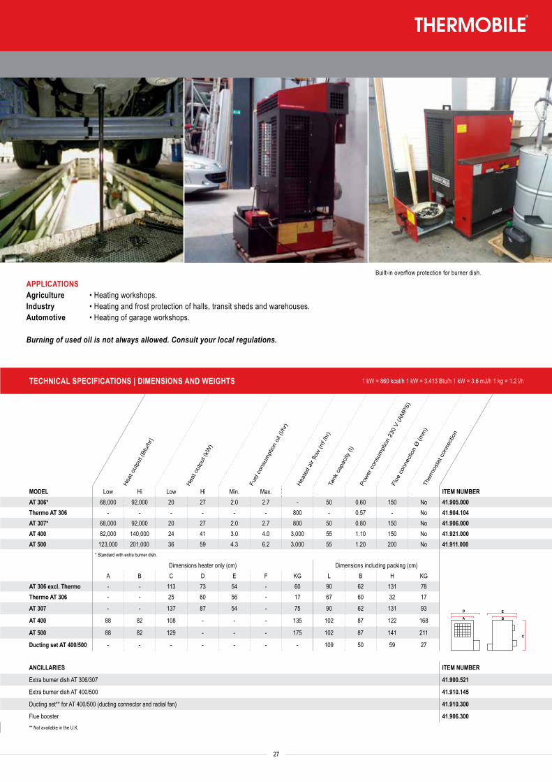
APPLICATIONSAgriculture • Heating workshops.Industry • Heating and frost protection of halls, transit sheds and warehouses.Automotive • Heating of garage workshops.
Burning of used oil is not always allowed. Consult your local regulations.
Built-in overflow protection for burner dish.
TECHNICAL SPECIFICATIONS | DIMENSIONS AND WEIGHTS 1 kW = 860 kcal/h 1 kW = 3,413 Btu/h 1 kW = 3.6 mJ/h 1 kg = 1.2 l/h
Heat
out
put (
Btu/
hr)
Heat
out
put (
kW)
Fuel
con
sum
ptio
n oi
l (l/h
r)
Heat
ed a
ir flo
w (m
3 /hr)
Tank
cap
acity
(l)
Powe
r con
sum
ptio
n 23
0 V
(AM
PS)
Flue
con
nect
ion
Ø (m
m)
Ther
mos
tat c
onne
ctio
n
MODEL Low Hi Low Hi Min. Max. ITEM NUMBERAT 306* 68,000 92,000 20 27 2.0 2.7 - 50 0.60 150 No 41.905.000Thermo AT 306 - - - - - - 800 - 0.57 - No 41.904.104AT 307* 68,000 92,000 20 27 2.0 2.7 800 50 0.80 150 No 41.906.000AT 400 82,000 140,000 24 41 3.0 4.0 3,000 55 1.10 150 No 41.921.000AT 500 123,000 201,000 36 59 4.3 6.2 3,000 55 1.20 200 No 41.911.000
* Standard with extra burner dish.
Dimensions heater only (cm) Dimensions including packing (cm)A B C D E F KG L B H KG
AT 306 excl. Thermo - - 113 73 54 - 60 90 62 131 78Thermo AT 306 - - 25 60 56 - 17 67 60 32 17
AT 307 - - 137 87 54 - 75 90 62 131 93
AT 400 88 82 108 - - - 135 102 87 122 168
AT 500 88 82 129 - - - 175 102 87 141 211
Ducting set AT 400/500 - - - - - - - 109 50 59 27
ANCILLARIES ITEM NUMBER
Extra burner dish AT 306/307 41.900.521
Extra burner dish AT 400/500 41.910.145
Ducting set** for AT 400/500 (ducting connector and radial fan) 41.910.300
Flue booster 41.906.300** Not available in the U.K.
TA
ITA
IMA
IMAC
GAGA EV
AGA ETAS 800 E
ATPRODRY
BioEnergy
BX, CH, VTB, TTV
FUEL TYPE
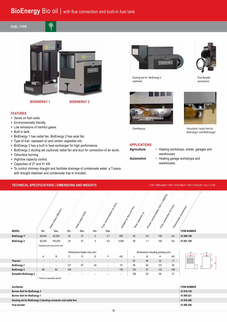
Ducting set for BioEnergy 2(optional)
Flue Booster (accessory)
Overflowcup Adjustable- height feet for BioEnergy1 and BioEnergy2
Heat
out
put (
Btu/
hr)
Heat
out
put (
kW)
Fuel
con
sum
ptio
n oi
l (l/h
r)
Heat
ed a
ir flo
w (m
3 /hr)
Tank
cap
acity
(l)
Powe
r con
sum
ptio
n 23
0 V
(AM
PS)
Flue
con
nect
ion
Ø (m
m)
Ther
mos
tat c
onne
ctio
n
MODEL Min. Max. Min. Max. Min. Max. ITEM NUMBER
BioEnergy 1* 68,000 92,000 20 27 2 2.7 800 50 0.8 150 No 41.906.150
BioEnergy 2 82,000 140,000 24 41 3 4.0 3,000 55 1.1 150 No 41.921.150* Standard with extra burner dish.
Dimensions heater only (cm) Dimensions including packing (cm)A B C D E F KG L B H KG
Thermo* - - - - - - - 67 60 32 17BioEnergy 1 - - 137 87 54 - 75 90 62 131 93BioEnergy 2 88 82 108 - - - 135 102 87 122 168Kanaalkit BioEnergy 2 - - - - - - - 109 50 59 27
* Thermo is separately packed.
Ancillaries ITEM NUMBERBurner dish for BioEnergy 2 41.910.145Burner dish for BioEnergy 1 41.900.521Ducting set for BioEnergy 2 (ducting connector and radial fan) 41.910.300Flue booster 41.906.300
TECHNICAL SPECIFICATIONS | DIMENSIONS AND WEIGHTS 1 kW = 860 kcal/h 1 kW = 3,413 Btu/h 1 kW = 3.6 mJ/h 1 kg = 1.2 l/h
TA
ITA
IMA
IMAC
GAGA EV
AGA ETAS 800 E
ATPRODRY
BioEnergy
BX, CH, VTB, TTV
Capa
city
(l/24
hr)
Capa
city
(l/24
hr)
Ope
ratin
g ra
nge
Air fl
ow (m
3 /u)
Powe
r con
sum
ptio
n 23
0 V
(AM
PS)
Tank
cap
acity
(l)
28
FEATURES· Saves on fuel costs.· Environmentally friendly.· Low emissions of harmful gases.· Built in tank.· BioEnergy 1 has radial fan, BioEnergy 2 has axial fan.· Type of fuel: rapeseed oil and certain vegetable oils.· BioEnergy 2 has a built in heat exchanger for high performance.· BioEnergy 2 ducting set (optional) radial fan and duct for connection of air ducts.· Odourless burning.· High/low capacity control.· Capacities of 27 and 41 kW.· To control chimney draught and facilitate drainage of condensate water, a T-piece
with draught stabiliser and condensate trap is included.
BioEnergy Bio oil | with flue connection and built-in fuel tank
BIOENERGY 1 BIOENERGY 2
APPLICATIONSAgriculture • Heating workshops, sheds, garages and
warehouses.Automotive • Heating garage workshops and
warehouses.
FUEL TYPE
Heat
out
put (
Btu/
hr)
Heat
out
put (
kW)
Fuel
con
sum
ptio
n oi
l (l/h
r)
Heat
ed a
ir flo
w (m
3 /hr)
Tank
cap
acity
(l)
Powe
r con
sum
ptio
n 23
0 V
(AM
PS)
Flue
con
nect
ion
Ø (m
m)
Ther
mos
tat c
onne
ctio
n
MODEL Min. Max. Min. Max. Min. Max. ITEM NUMBER
BioEnergy 1* 68,000 92,000 20 27 2 2.7 800 50 0.8 150 No 41.906.150
BioEnergy 2 82,000 140,000 24 41 3 4.0 3,000 55 1.1 150 No 41.921.150* Standard with extra burner dish.
Dimensions heater only (cm) Dimensions including packing (cm)A B C D E F KG L B H KG
Thermo* - - - - - - - 67 60 32 17BioEnergy 1 - - 137 87 54 - 75 90 62 131 93BioEnergy 2 88 82 108 - - - 135 102 87 122 168Kanaalkit BioEnergy 2 - - - - - - - 109 50 59 27
* Thermo is separately packed.
Ancillaries ITEM NUMBERBurner dish for BioEnergy 2 41.910.145Burner dish for BioEnergy 1 41.900.521Ducting set for BioEnergy 2 (ducting connector and radial fan) 41.910.300Flue booster 41.906.300
TECHNICAL SPECIFICATIONS | DIMENSIONS AND WEIGHTS 1 kW = 860 kcal/h 1 kW = 3,413 Btu/h 1 kW = 3.6 mJ/h 1 kg = 1.2 l/h
Capa
city
(l/24
hr)
Capa
city
(l/24
hr)
Ope
ratin
g ra
nge
Air fl
ow (m
3 /u)
Powe
r con
sum
ptio
n 23
0 V
(AM
PS)
Tank
cap
acity
(l)
MODEL Max. 20 °C/60% RH 27 °C/80% RH 32 °C/80% RV °C % RV ITEM NUMBERProDry TD45 44 18 37 44 3-32 50-90 700 1.0 8.3 50.600.350ProDry TD80 79 29 56 79 3-32 50-90 1,380 1.2 8.3 50.600.600ProDry TD100 100 44 79 100 3-32 50-90 1,380 1.9 15.7 50.600.900Condensate pump 50.600.400
Dimensions ProDry only (cm) Dimensions including packing (cm)A B C D E F KG L B H KG
ProDry TD45 - - 89.5 52.5 54.5 - 37 - - - -ProDry TD80 - - 96.5 56.0 54.5 - 46 - - - -ProDry TD100 - - 107.5 62.0 59.0 - 50 - - - -
E
C
D
29
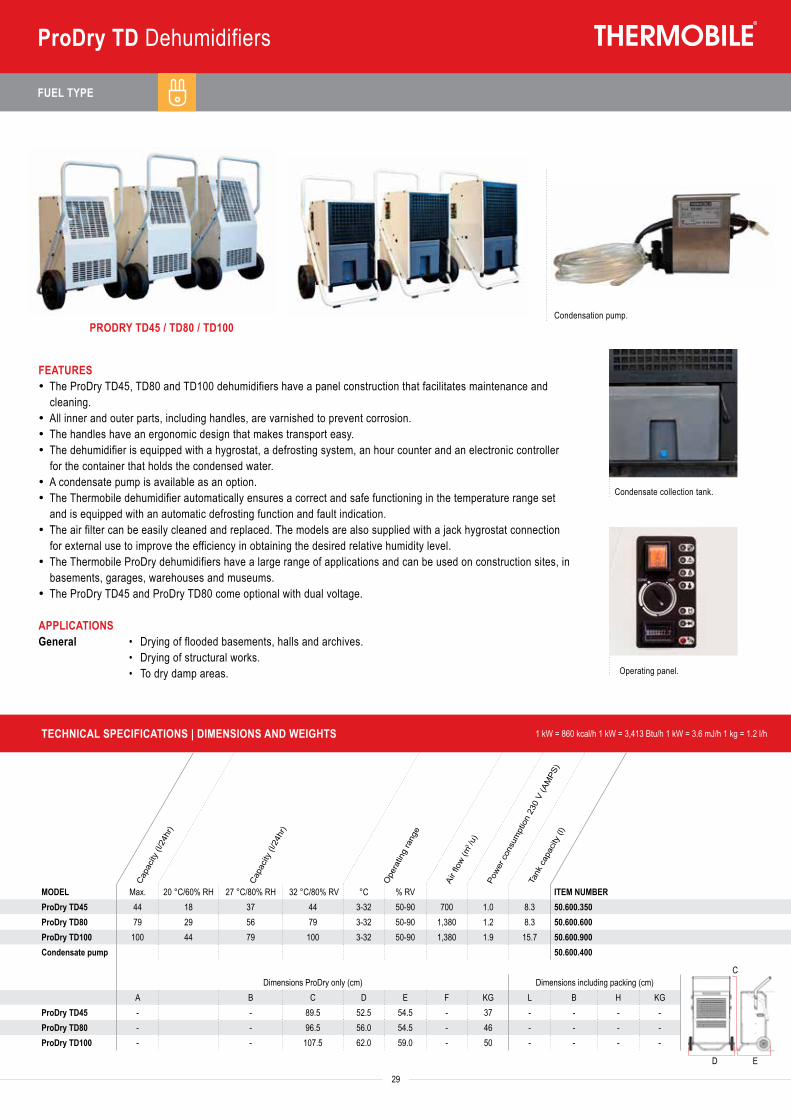
ProDry TD Dehumidifiers
FEATURES· The ProDry TD45, TD80 and TD100 dehumidifiers have a panel construction that facilitates maintenance and
cleaning.· All inner and outer parts, including handles, are varnished to prevent corrosion.· The handles have an ergonomic design that makes transport easy.· The dehumidifier is equipped with a hygrostat, a defrosting system, an hour counter and an electronic controller
for the container that holds the condensed water.· A condensate pump is available as an option.· The Thermobile dehumidifier automatically ensures a correct and safe functioning in the temperature range set
and is equipped with an automatic defrosting function and fault indication.· The air filter can be easily cleaned and replaced. The models are also supplied with a jack hygrostat connection
for external use to improve the efficiency in obtaining the desired relative humidity level.· The Thermobile ProDry dehumidifiers have a large range of applications and can be used on construction sites, in
basements, garages, warehouses and museums.· The ProDry TD45 and ProDry TD80 come optional with dual voltage.
APPLICATIONSGeneral • Drying of flooded basements, halls and archives. • Drying of structural works. • To dry damp areas.
PRODRY TD45 / TD80 / TD100Condensation pump.
Operating panel.
Condensate collection tank.
FUEL TYPE
Heat
out
put (
Btu/
hr)
Heat
out
put (
kW)
Volta
ge (V
)
Heat
ed a
ir flo
w (m
3 /hr)
Adju
stm
ent r
ange
(kW
)De
lta T
(°C)
Powe
r con
sum
ptio
n (A
MPS
)O
utle
t con
nect
ion
Ø (m
m)
Ther
mos
tat
30
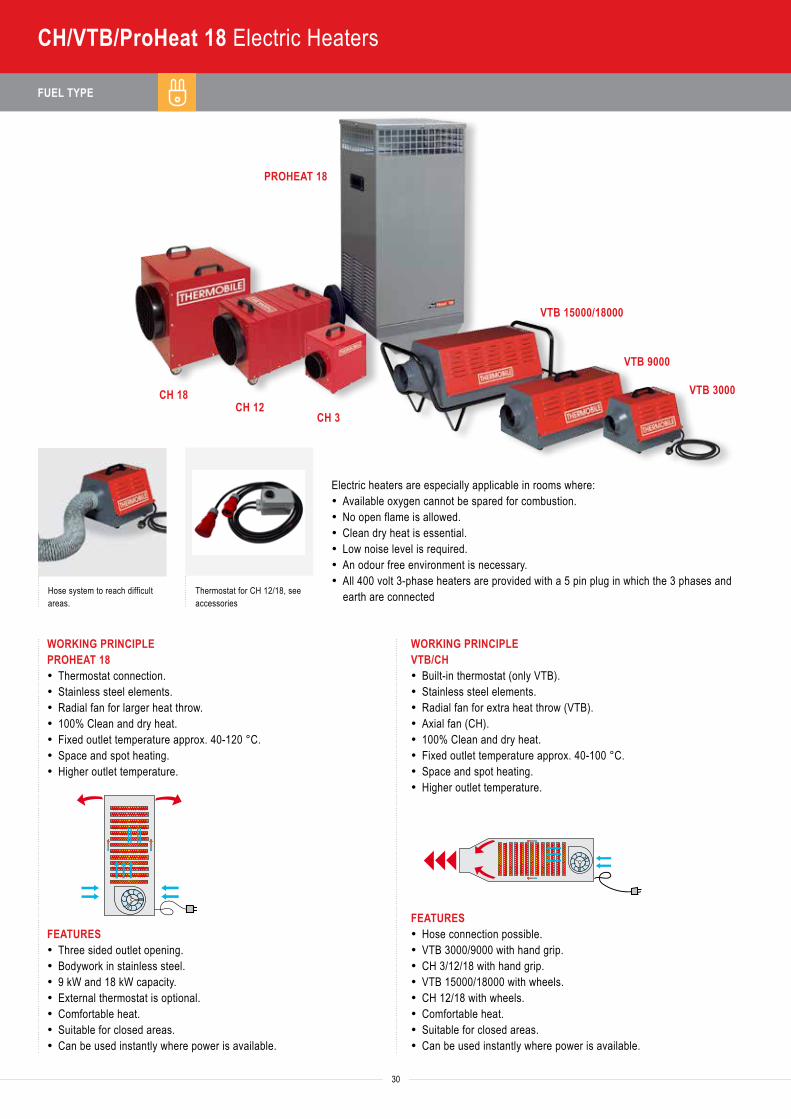
CH/VTB/ProHeat 18 Electric Heaters
PROHEAT 18
CH 18CH 12
CH 3
VTB 15000/18000
VTB 9000
VTB 3000
Electric heaters are especially applicable in rooms where:· Available oxygen cannot be spared for combustion.· No open flame is allowed.· Clean dry heat is essential.· Low noise level is required.· An odour free environment is necessary.· All 400 volt 3-phase heaters are provided with a 5 pin plug in which the 3 phases and
earth are connectedHose system to reach difficult areas.
Thermostat for CH 12/18, see accessories
WORKING PRINCIPLEPROHEAT 18· Thermostat connection.· Stainless steel elements.· Radial fan for larger heat throw.· 100% Clean and dry heat.· Fixed outlet temperature approx. 40-120 °C.· Space and spot heating.· Higher outlet temperature.
FEATURES· Three sided outlet opening.· Bodywork in stainless steel.· 9 kW and 18 kW capacity.· External thermostat is optional.· Comfortable heat.· Suitable for closed areas.· Can be used instantly where power is available.
WORKING PRINCIPLEVTB/CH· Built-in thermostat (only VTB).· Stainless steel elements.· Radial fan for extra heat throw (VTB).· Axial fan (CH).· 100% Clean and dry heat.· Fixed outlet temperature approx. 40-100 °C.· Space and spot heating.· Higher outlet temperature.
FEATURES· Hose connection possible.· VTB 3000/9000 with hand grip.· CH 3/12/18 with hand grip.· VTB 15000/18000 with wheels.· CH 12/18 with wheels.· Comfortable heat.· Suitable for closed areas.· Can be used instantly where power is available.
TECHNICAL SPECIFICATIONS | DIMENSIONS AND WEIGHTS 1 kW = 860 kcal/h 1 kW = 3,413 Btu/h 1 kW = 3.6 mJ/h 1 kg = 1.2 l/h
Heat
out
put (
Btu/
hr)
Heat
out
put (
kW)
Volta
ge (V
)
Heat
ed a
ir flo
w (m
3 /hr)
Adju
stm
ent r
ange
(kW
)De
lta T
(°C)
Powe
r con
sum
ptio
n (A
MPS
)O
utle
t con
nect
ion
Ø (m
m)
Ther
mos
tat
MODEL Min. Max. ITEM NUMBERProHeat 18 3,4) 61,000 18 3x400 - 1,000 0-9-18 120 13-26 - Yes 40.018.000VTB 3000 1) 9,560 3 1x230 - 225 0-3 60 13 98 Yes 40.107.030VTB 9000 2) 31,000 9 3x400 - 550 0-4.5-9 100 11,5-13 120 Yes 40.107.035VTB 15000 3) 51,000 15 3x400 - 1,000 0-6-9-15 38-60-100 8-14-23 150 Yes 40.107.025VTB 18000 3) 61,000 18 3x400 - 1,000 0-9-18 70-110 14-26 150 Yes 40.107.040CH 3 1) 10,000 3 1x230 - 250 0-3 60 13 160 External 40.107.091CH 12 3) 41,000 12 3x400 - 600 0-6-9-12 100 18 300 External 40.107.092CH 18 3) 61,000 18 3x400 - 1,500 0-9-13.5-18 90 26 300 External 40.107.093
1) with 230 V-cable 2) with 400 V-cable and 16 AMPS plug 3) with 400 V-cable + 32 AMPS plug 4) Provide with thermostat connection.
Dimensions heater only (cm) Dimensions including packing (cm)
A B C D E F KG L B H KG
ProHeat 18 - 40 97 51 - - 40 107 70 57 53
VTB 3000 - 34 31 40 - - 11 45 36 35 12
VTB 9000 - 34 31 68 - - 18 72 36 35 21
VTB 15000 - 86 52 48 - - 33 102 46 51 39
VTB 18000 - 86 52 48 - - 33 102 46 51 39
CH 3 38 28 39 - - - 11 38 28 38 13
CH 12 66 37 45 - - - 23 65 37 45 25
CH 18 55 43 58 - - - 28 55 42 58 30
TA
ITA
IMA
IMAC
GAGA EV
AGA ETAS 800 E
ATPRODRY
BioEnergy
BX, CH, VTB, TTV
TA
ITA
IMA
IMAC
GAGA EV
AGA ETAS 800 E
ATPRODRY
BioEnergy
BX, CH, VTB, TTV
31
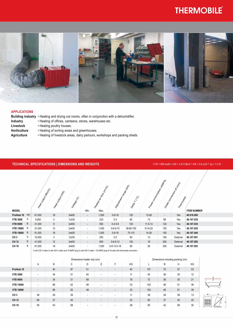
APPLICATIONSBuilding industry • Heating and drying out rooms, often in conjunction with a dehumidifier.Industry • Heating of offices, canteens, stores, warehouses etc.Livestock • Heating poultry houses.Horticulture • Heating of sorting areas and greenhouses.Agriculture • Heating of livestock areas, dairy parlours, workshops and packing sheds.
FUEL TYPE
Air�ow 3960 m3/h
>75°C 55°C
32
BX/TBD 18 Electric Heaters
BX 15
BX 9
BX 3
BX 20/30TBD 18 PC
TBD 18
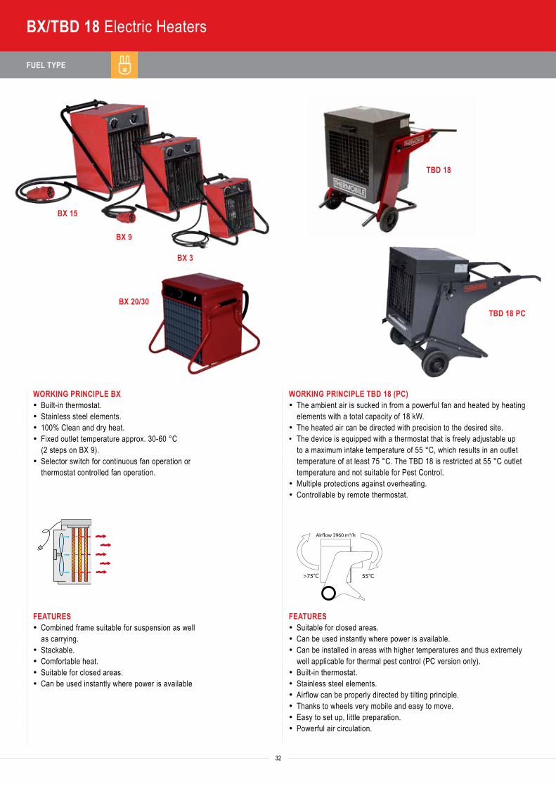
WORKING PRINCIPLE BX· Built-in thermostat.· Stainless steel elements.· 100% Clean and dry heat.· Fixed outlet temperature approx. 30-60 °C
(2 steps on BX 9).· Selector switch for continuous fan operation or
thermostat controlled fan operation.
FEATURES· Combined frame suitable for suspension as well
as carrying.· Stackable.· Comfortable heat.· Suitable for closed areas.· Can be used instantly where power is available
WORKING PRINCIPLE TBD 18 (PC)· The ambient air is sucked in from a powerful fan and heated by heating
elements with a total capacity of 18 kW.· The heated air can be directed with precision to the desired site.• The device is equipped with a thermostat that is freely adjustable up
to a maximum intake temperature of 55 °C, which results in an outlet temperature of at least 75 °C. The TBD 18 is restricted at 55 °C outlet temperature and not suitable for Pest Control.
· Multiple protections against overheating.· Controllable by remote thermostat.
FEATURES· Suitable for closed areas.· Can be used instantly where power is available.· Can be installed in areas with higher temperatures and thus extremely
well applicable for thermal pest control (PC version only).· Built-in thermostat.· Stainless steel elements.· Airflow can be properly directed by tilting principle.· Thanks to wheels very mobile and easy to move.· Easy to set up, little preparation.· Powerful air circulation.
Heat
out
put (
Btu/
hr)
Heat
out
put (
kW)
Volta
ge (V
)
Heat
ed a
ir flo
w (m
3 /hr)
Adju
stm
ent r
ange
(kW
)De
lta T
(°C)
Powe
r con
sum
ptio
n (A
MPS
)O
utle
t con
nect
ion
Ø (m
m)
Ther
mos
tat
33
TBD 18 PC
TBD 18
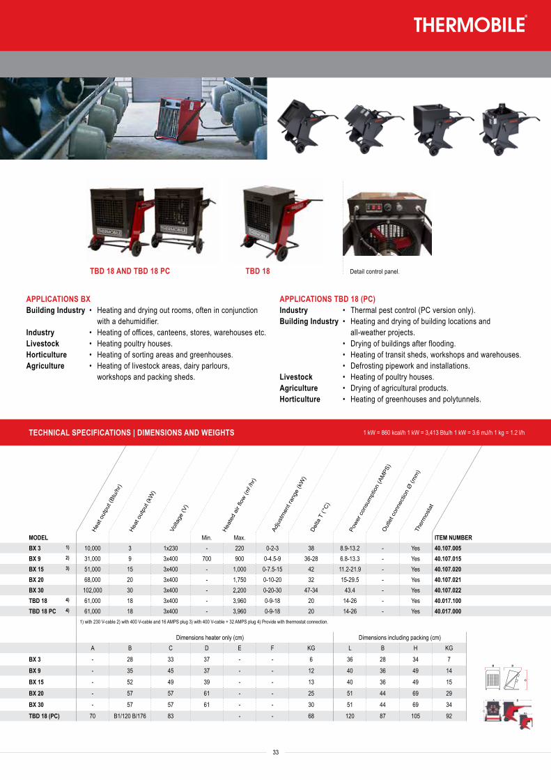
APPLICATIONS BXBuilding Industry • Heating and drying out rooms, often in conjunction
with a dehumidifier.Industry • Heating of offices, canteens, stores, warehouses etc.Livestock • Heating poultry houses.Horticulture • Heating of sorting areas and greenhouses.Agriculture • Heating of livestock areas, dairy parlours,
workshops and packing sheds.
APPLICATIONS TBD 18 (PC)Industry • Thermal pest control (PC version only).Building Industry • Heating and drying of building locations and
all-weather projects. • Drying of buildings after flooding. • Heating of transit sheds, workshops and warehouses. • Defrosting pipework and installations.Livestock • Heating of poultry houses.Agriculture • Drying of agricultural products.Horticulture • Heating of greenhouses and polytunnels.
TBD 18 AND TBD 18 PC Detail control panel.
Heat
out
put (
Btu/
hr)
Heat
out
put (
kW)
Volta
ge (V
)
Heat
ed a
ir flo
w (m
3 /hr)
Adju
stm
ent r
ange
(kW
)De
lta T
(°C)
Powe
r con
sum
ptio
n (A
MPS
)O
utle
t con
nect
ion
Ø (m
m)
Ther
mos
tat
MODEL Min. Max. ITEM NUMBERBX 3 1) 10,000 3 1x230 - 220 0-2-3 38 8.9-13.2 - Yes 40.107.005BX 9 2) 31,000 9 3x400 700 900 0-4.5-9 36-28 6.8-13.3 - Yes 40.107.015BX 15 3) 51,000 15 3x400 - 1,000 0-7.5-15 42 11.2-21.9 - Yes 40.107.020BX 20 68,000 20 3x400 - 1,750 0-10-20 32 15-29.5 - Yes 40.107.021BX 30 102,000 30 3x400 - 2,200 0-20-30 47-34 43.4 - Yes 40.107.022TBD 18 4) 61,000 18 3x400 - 3,960 0-9-18 20 14-26 - Yes 40.017.100TBD 18 PC 4) 61,000 18 3x400 - 3,960 0-9-18 20 14-26 - Yes 40.017.000
1) with 230 V-cable 2) with 400 V-cable and 16 AMPS plug 3) with 400 V-cable + 32 AMPS plug 4) Provide with thermostat connection.
Dimensions heater only (cm) Dimensions including packing (cm)A B C D E F KG L B H KG
BX 3 - 28 33 37 - - 6 36 28 34 7
BX 9 - 35 45 37 - - 12 40 36 49 14
BX 15 - 52 49 39 - - 13 40 36 49 15
BX 20 - 57 57 61 - - 25 51 44 69 29
BX 30 - 57 57 61 - - 30 51 44 69 34
TBD 18 (PC) 70 B1/120 B/176 83 - - 68 120 87 105 92
TECHNICAL SPECIFICATIONS | DIMENSIONS AND WEIGHTS 1 kW = 860 kcal/h 1 kW = 3,413 Btu/h 1 kW = 3.6 mJ/h 1 kg = 1.2 l/h
TA
ITA
IMA
IMAC
GAGA EV
AGA ETAS 800 E
ATPRODRY
BioEnergy
BX, CH, VTB, TTV
TA
ITA
IMA
IMAC
GAGA EV
AGA ETAS 800 E
ATPRODRY
BioEnergy
BX, CH, VTB, TTVBA
CB1
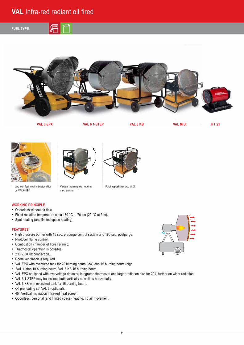
FUEL TYPE
34
VAL Infra-red radiant oil fired
VAL 6 EPX VAL 6 1-STEP VAL 6 KB VAL MIDI IFT 21
VAL with fuel level indicator. (Not on VAL 6 KB.)
Vertical inclining with locking mechanism.
Folding push bar VAL MIDI.
WORKING PRINCIPLE· Odourless without air flow.· Fixed radiation temperature circa 150 °C at 70 cm (20 °C at 3 m).· Spot heating (and limited space heating).
FEATURES· High pressure burner with 15 sec. prepurge control system and 180 sec. postpurge.· Photocell flame control.· Combustion chamber of fibre ceramic.· Thermostat operation is possible.· 230 V/50 Hz connection.· Room ventilation is required.· VAL EPX with oversized tank for 20 burning hours (low) and 15 burning hours (high• VAL 1-step 10 burning hours, VAL 6 KB 16 burning hours.· VAL EPX equipped with overvoltage detector, integrated thermostat and larger radiation disc for 20% further en wider radiation.· VAL 6 1-STEP may be inclined both vertically as well as horizontally.· VAL 6 KB with oversized tank for 16 burning hours. · Oil preheating set VAL 6 (optional).· 45° Vertical inclination infra-red heat screen.· Odourless, personal (and limited space) heating, no air movement.
Heat
out
put (
Btu/
h)He
at o
utpu
t (kW
)
Fuel
con
sum
ptio
n oi
l max
. (l/h
)Ta
nk c
apac
ity (l
)Po
wer c
onsu
mpt
ion
230
V (A
MPS
)
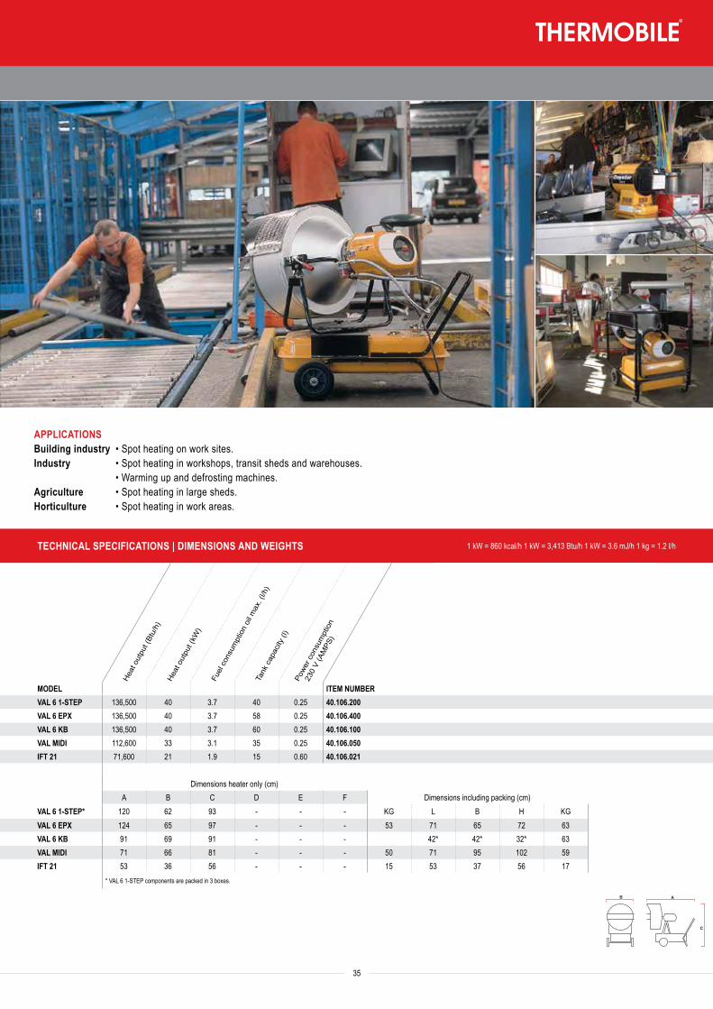
35
APPLICATIONSBuilding industry • Spot heating on work sites.Industry • Spot heating in workshops, transit sheds and warehouses. • Warming up and defrosting machines.Agriculture • Spot heating in large sheds.Horticulture • Spot heating in work areas.
TECHNICAL SPECIFICATIONS | DIMENSIONS AND WEIGHTS 1 kW = 860 kcal/h 1 kW = 3,413 Btu/h 1 kW = 3.6 mJ/h 1 kg = 1.2 l/h
Heat
out
put (
Btu/
h)He
at o
utpu
t (kW
)
Fuel
con
sum
ptio
n oi
l max
. (l/h
)Ta
nk c
apac
ity (l
)Po
wer c
onsu
mpt
ion
230
V (A
MPS
)
MODEL ITEM NUMBERVAL 6 1-STEP 136,500 40 3.7 40 0.25 40.106.200VAL 6 EPX 136,500 40 3.7 58 0.25 40.106.400VAL 6 KB 136,500 40 3.7 60 0.25 40.106.100VAL MIDI 112,600 33 3.1 35 0.25 40.106.050IFT 21 71,600 21 1.9 15 0.60 40.106.021
Dimensions heater only (cm)A B C D E F Dimensions including packing (cm)
VAL 6 1-STEP* 120 62 93 - - - KG L B H KGVAL 6 EPX 124 65 97 - - - 53 71 65 72 63VAL 6 KB 91 69 91 - - - 42* 42* 32* 63VAL MIDI 71 66 81 - - - 50 71 95 102 59IFT 21 53 36 56 - - - 15 53 37 56 17
* VAL 6 1-STEP components are packed in 3 boxes.
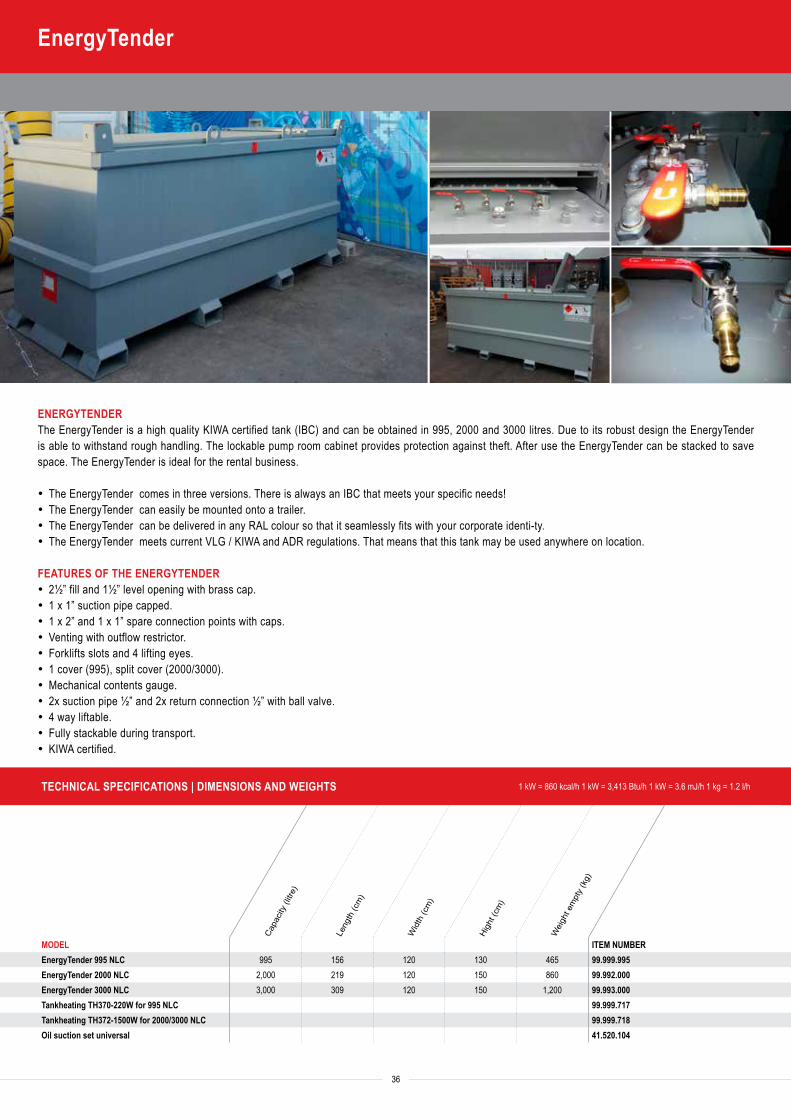
TECHNICAL SPECIFICATIONS | DIMENSIONS AND WEIGHTS 1 kW = 860 kcal/h 1 kW = 3,413 Btu/h 1 kW = 3.6 mJ/h 1 kg = 1.2 l/h
Capa
city
(litre
)
Leng
th (c
m)
Wid
th (c
m)
High
t (cm
)
Wei
ght e
mpt
y (k
g)
MODEL ITEM NUMBEREnergyTender 995 NLC 995 156 120 130 465 99.999.995EnergyTender 2000 NLC 2,000 219 120 150 860 99.992.000EnergyTender 3000 NLC 3,000 309 120 150 1,200 99.993.000Tankheating TH370-220W for 995 NLC 99.999.717Tankheating TH372-1500W for 2000/3000 NLC 99.999.718Oil suction set universal 41.520.104
Capa
city
(litre
)
Leng
th (c
m)
Wid
th (c
m)
High
t (cm
)
Wei
ght e
mpt
y (k
g)
Mul
titan
k 70
0 litr
es
Mul
titan
k 10
00 lit
res
36
EnergyTender
ENERGYTENDERThe EnergyTender is a high quality KIWA certified tank (IBC) and can be obtained in 995, 2000 and 3000 litres. Due to its robust design the EnergyTender is able to withstand rough handling. The lockable pump room cabinet provides protection against theft. After use the EnergyTender can be stacked to save space. The EnergyTender is ideal for the rental business.
· The EnergyTender comes in three versions. There is always an IBC that meets your specific needs!· The EnergyTender can easily be mounted onto a trailer.· The EnergyTender can be delivered in any RAL colour so that it seamlessly fits with your corporate identi-ty.· The EnergyTender meets current VLG / KIWA and ADR regulations. That means that this tank may be used anywhere on location.
FEATURES OF THE ENERGYTENDER· 2½” fill and 1½” level opening with brass cap. · 1 x 1” suction pipe capped. · 1 x 2” and 1 x 1” spare connection points with caps. · Venting with outflow restrictor. · Forklifts slots and 4 lifting eyes. · 1 cover (995), split cover (2000/3000). · Mechanical contents gauge. · 2x suction pipe ½” and 2x return connection ½” with ball valve. · 4 way liftable. · Fully stackable during transport. · KIWA certified.
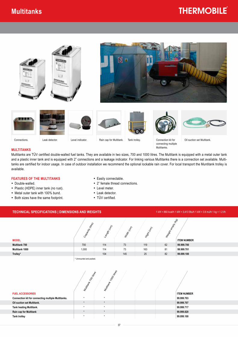
Capa
city
(litre
)
Leng
th (c
m)
Wid
th (c
m)
High
t (cm
)
Wei
ght e
mpt
y (k
g)
MODEL ITEM NUMBEREnergyTender 995 NLC 995 156 120 130 465 99.999.995EnergyTender 2000 NLC 2,000 219 120 150 860 99.992.000EnergyTender 3000 NLC 3,000 309 120 150 1,200 99.993.000Tankheating TH370-220W for 995 NLC 99.999.717Tankheating TH372-1500W for 2000/3000 NLC 99.999.718Oil suction set universal 41.520.104
TECHNICAL SPECIFICATIONS | DIMENSIONS AND WEIGHTS 1 kW = 860 kcal/h 1 kW = 3,413 Btu/h 1 kW = 3.6 mJ/h 1 kg = 1.2 l/h
Capa
city
(litre
)
Leng
th (c
m)
Wid
th (c
m)
High
t (cm
)
Wei
ght e
mpt
y (k
g)
Mul
titan
k 70
0 litr
es
Mul
titan
k 10
00 lit
res
MODEL ITEM NUMBERMultitank 700 700 114 73 119 62 99.999.700Multitank 1000 1,000 114 73 163 81 99.999.701Trolley* 104 145 25 82 99.099.100
* Unmounted and packed.
FUEL ACCESSORIES ITEM NUMBERConnection kit for connecting multiple Multitanks. * * 99.999.703Oil suction set Multitank. * * 99.999.707Tank heating Multitank. * * 99.999.717Rain cap for Multitank * * 99.999.820Tank trolley * * 99.099.100
37
Multitanks
MULTITANKS Multitanks are TÜV certified double-walled fuel tanks. They are available in two sizes, 700 and 1000 litres. The Multitank is equipped with a metal outer tank and a plastic inner tank and is equipped with 2” connections and a leakage indicator. For linking various Multitanks there is a connection set available. Multi-tanks are certified for indoor usage. In case of outdoor installation we recommend the optional lockable rain cover. For local transport the Muntitank trolley is available.
FEATURES OF THE MULTITANKS· Double-walled. · Plastic (HDPE) inner tank (no rust). · Metal outer tank with 100% bund. · Both sizes have the same footprint.
Tank trolley.Connections. Leak detector. Connection kit for connecting multiple Multitanks.
Level indicator. Rain cap for Multitank. Oil suction set Multitank.
· Easily connectable. · 2” female thread connections. · Level meter. · Leak detector. · TÜV certified.
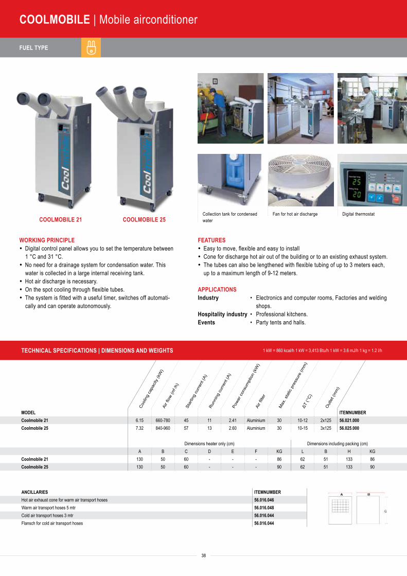
FUEL TYPE
38
COOLMOBILE | Mobile airconditioner
COOLMOBILE 21 COOLMOBILE 25Collection tank for condensed water
Fan for hot air discharge Digital thermostat
WORKING PRINCIPLE· Digital control panel allows you to set the temperature between
1 °C and 31 °C.· No need for a drainage system for condensation water. This
water is collected in a large internal receiving tank.· Hot air discharge is necessary.· On the spot cooling through flexible tubes.· The system is fitted with a useful timer, switches off automati-
cally and can operate autonomously.
FEATURES· Easy to move, flexible and easy to install · Cone for discharge hot air out of the building or to an existing exhaust system.· The tubes can also be lengthened with flexible tubing of up to 3 meters each,
up to a maximum length of 9-12 meters. APPLICATIONSIndustry • Electronics and computer rooms, Factories and welding
shops.Hospitality industry • Professional kitchens.Events • Party tents and halls.
Cool
ing
capa
city
(kW
)Ai
r flow
(m3 /h
)
Star
ting
curre
nt (A
)Ru
nnin
g cu
rrent
(A)
Powe
r con
sum
ptio
n (k
W)
Air fi
lter
Max
. sta
tic p
ress
ure
(mm
)ΔT
(°C)
Out
let (
mm
)
MODEL ITEMNUMBERCoolmobile 21 6.15 660-780 45 11 2.41 Aluminium 30 10-12 2x125 56.021.000Coolmobile 25 7.32 840-960 57 13 2.60 Aluminium 30 10-15 3x125 56.025.000
Dimensions heater only (cm) Dimensions including packing (cm)A B C D E F KG L B H KG
Coolmobile 21 130 50 60 - - - 86 62 51 133 86Coolmobile 25 130 50 60 - - - 90 62 51 133 90
ANCILLARIES ITEMNUMBER
Hot air exhaust cone for warm air transport hoses 56.016.046Warm air transport hoses 5 mtr 56.016.048Cold air transport hoses 3 mtr 56.016.044Flansch for cold air transport hoses 56.016.044
TECHNICAL SPECIFICATIONS | DIMENSIONS AND WEIGHTS 1 kW = 860 kcal/h 1 kW = 3,413 Btu/h 1 kW = 3.6 mJ/h 1 kg = 1.2 l/h
Cool
ing
capa
city
(kW
)He
atin
g ca
pacit
y (k
W)
Airfl
ow (m
3 /h)
Powe
r con
sum
ptio
n (k
W)
Supp
ly vo
ltage
(V/p
h/Hz
)Re
frige
rant
type
Air o
utle
t con
e Ø
(mm
)Ai
r inl
et c
one
Ø (m
m)
Ther
mos
tat c
onne
ctio
n
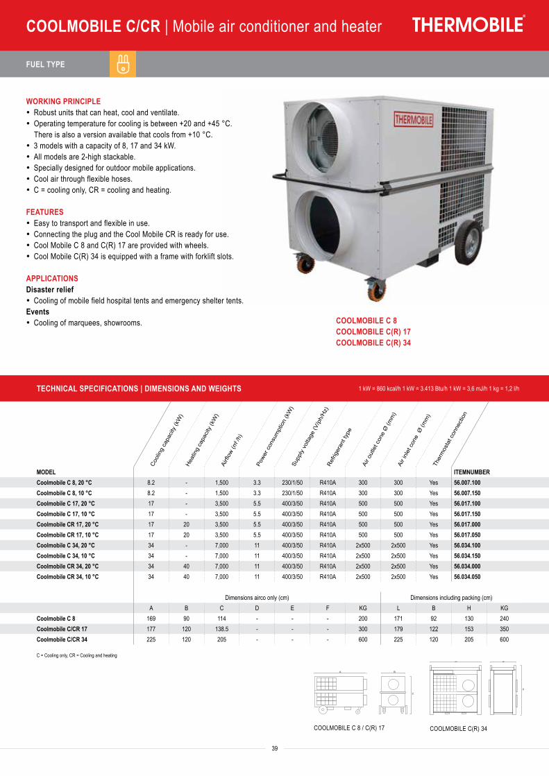
FUEL TYPE
39
COOLMOBILE C/CR | Mobile air conditioner and heater
Cool
ing
capa
city
(kW
)Ai
r flow
(m3 /h
)
Star
ting
curre
nt (A
)Ru
nnin
g cu
rrent
(A)
Powe
r con
sum
ptio
n (k
W)
Air fi
lter
Max
. sta
tic p
ress
ure
(mm
)ΔT
(°C)
Out
let (
mm
)
MODEL ITEMNUMBERCoolmobile 21 6.15 660-780 45 11 2.41 Aluminium 30 10-12 2x125 56.021.000Coolmobile 25 7.32 840-960 57 13 2.60 Aluminium 30 10-15 3x125 56.025.000
Dimensions heater only (cm) Dimensions including packing (cm)A B C D E F KG L B H KG
Coolmobile 21 130 50 60 - - - 86 62 51 133 86Coolmobile 25 130 50 60 - - - 90 62 51 133 90
ANCILLARIES ITEMNUMBER
Hot air exhaust cone for warm air transport hoses 56.016.046Warm air transport hoses 5 mtr 56.016.048Cold air transport hoses 3 mtr 56.016.044Flansch for cold air transport hoses 56.016.044
WORKING PRINCIPLE· Robust units that can heat, cool and ventilate.· Operating temperature for cooling is between +20 and +45 °C.
There is also a version available that cools from +10 °C.· 3 models with a capacity of 8, 17 and 34 kW.· All models are 2-high stackable.· Specially designed for outdoor mobile applications.· Cool air through flexible hoses.· C = cooling only, CR = cooling and heating. FEATURES· Easy to transport and flexible in use.· Connecting the plug and the Cool Mobile CR is ready for use.· Cool Mobile C 8 and C(R) 17 are provided with wheels.· Cool Mobile C(R) 34 is equipped with a frame with forklift slots.
APPLICATIONSDisaster relief· Cooling of mobile field hospital tents and emergency shelter tents.Events· Cooling of marquees, showrooms.
COOLMOBILE C 8 / C(R) 17 COOLMOBILE C(R) 34
COOLMOBILE C 8COOLMOBILE C(R) 17COOLMOBILE C(R) 34
A B
C
A B
C
TECHNICAL SPECIFICATIONS | DIMENSIONS AND WEIGHTS 1 kW = 860 kcal/h 1 kW = 3.413 Btu/h 1 kW = 3,6 mJ/h 1 kg = 1,2 l/h
Cool
ing
capa
city
(kW
)He
atin
g ca
pacit
y (k
W)
Airfl
ow (m
3 /h)
Powe
r con
sum
ptio
n (k
W)
Supp
ly vo
ltage
(V/p
h/Hz
)Re
frige
rant
type
Air o
utle
t con
e Ø
(mm
)Ai
r inl
et c
one
Ø (m
m)
Ther
mos
tat c
onne
ctio
n
MODEL ITEMNUMBERCoolmobile C 8, 20 °C 8.2 - 1,500 3.3 230/1/50 R410A 300 300 Yes 56.007.100Coolmobile C 8, 10 °C 8.2 - 1,500 3.3 230/1/50 R410A 300 300 Yes 56.007.150Coolmobile C 17, 20 °C 17 - 3,500 5.5 400/3/50 R410A 500 500 Yes 56.017.100Coolmobile C 17, 10 °C 17 - 3,500 5.5 400/3/50 R410A 500 500 Yes 56.017.150Coolmobile CR 17, 20 °C 17 20 3,500 5.5 400/3/50 R410A 500 500 Yes 56.017.000Coolmobile CR 17, 10 °C 17 20 3,500 5.5 400/3/50 R410A 500 500 Yes 56.017.050Coolmobile C 34, 20 °C 34 - 7,000 11 400/3/50 R410A 2x500 2x500 Yes 56.034.100Coolmobile C 34, 10 °C 34 - 7,000 11 400/3/50 R410A 2x500 2x500 Yes 56.034.150Coolmobile CR 34, 20 °C 34 40 7,000 11 400/3/50 R410A 2x500 2x500 Yes 56.034.000Coolmobile CR 34, 10 °C 34 40 7,000 11 400/3/50 R410A 2x500 2x500 Yes 56.034.050
Dimensions airco only (cm) Dimensions including packing (cm)A B C D E F KG L B H KG
Coolmobile C 8 169 90 114 - - - 200 171 92 130 240Coolmobile C/CR 17 177 120 138.5 - - - 300 179 122 153 350Coolmobile C/CR 34 225 120 205 - - - 600 225 120 205 600
C = Cooling only, CR = Cooling and heating
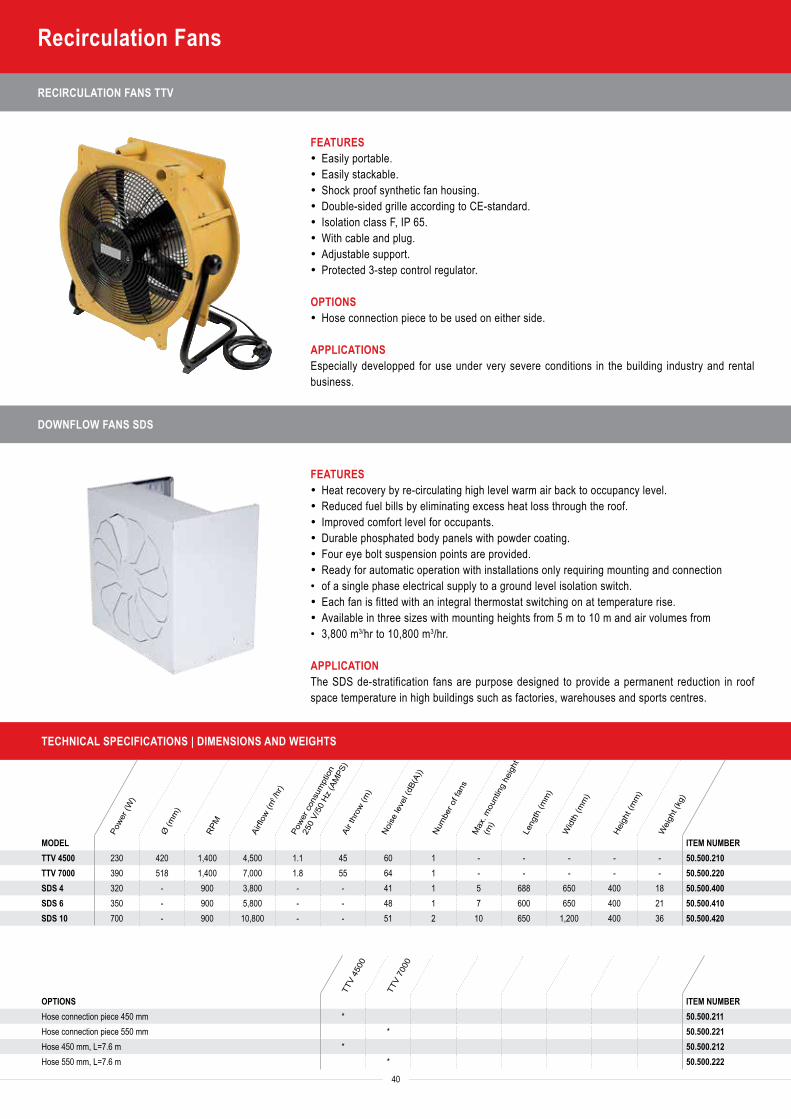
RECIRCULATION FANS TTV
FEATURES· Easily portable.· Easily stackable.· Shock proof synthetic fan housing.· Double-sided grille according to CE-standard.· Isolation class F, IP 65.· With cable and plug.· Adjustable support.· Protected 3-step control regulator.
OPTIONS· Hose connection piece to be used on either side.
APPLICATIONSEspecially developped for use under very severe conditions in the building industry and rental business.
DOWNFLOW FANS SDS
FEATURES· Heat recovery by re-circulating high level warm air back to occupancy level.· Reduced fuel bills by eliminating excess heat loss through the roof.· Improved comfort level for occupants.· Durable phosphated body panels with powder coating. · Four eye bolt suspension points are provided. · Ready for automatic operation with installations only requiring mounting and connection• of a single phase electrical supply to a ground level isolation switch.· Each fan is fitted with an integral thermostat switching on at temperature rise. · Available in three sizes with mounting heights from 5 m to 10 m and air volumes from• 3,800 m3/hr to 10,800 m3/hr.
APPLICATIONThe SDS de-stratification fans are purpose designed to provide a permanent reduction in roof space temperature in high buildings such as factories, warehouses and sports centres.
TECHNICAL SPECIFICATIONS | DIMENSIONS AND WEIGHTS
Powe
r (W
)
Ø (m
m)
RPM
Airfl
ow (m
3 /hr)
Powe
r con
sum
ptio
n
250
V/50
Hz
(AM
PS)
Air t
hrow
(m)
Noise
leve
l (dB
(A))
Num
ber o
f fan
sM
ax. m
ount
ing
heig
ht
(m)
Leng
th (m
m)
Wid
th (m
m)
Heig
ht (m
m)
Wei
ght (
kg)
MODEL ITEM NUMBERTTV 4500 230 420 1,400 4,500 1.1 45 60 1 - - - - - 50.500.210TTV 7000 390 518 1,400 7,000 1.8 55 64 1 - - - - - 50.500.220SDS 4 320 - 900 3,800 - - 41 1 5 688 650 400 18 50.500.400SDS 6 350 - 900 5,800 - - 48 1 7 600 650 400 21 50.500.410SDS 10 700 - 900 10,800 - - 51 2 10 650 1,200 400 36 50.500.420
40
Recirculation Fans
TTV
4500
TTV
7000
OPTIONS ITEM NUMBERHose connection piece 450 mm * 50.500.211Hose connection piece 550 mm * 50.500.221Hose 450 mm, L=7.6 m * 50.500.212Hose 550 mm, L=7.6 m * 50.500.222
TA TAS
ITA
IMA
IMAC
GA
AGA
ProH
eat 1
8
CH 1
2/18
Cool
mob
ile
CR
IMA
61/6
5 EC
IMA
111
IMA
150
IMA
200
IMAC
200
0 S
ISA
65
TA 2
2/30
TA 4
0
TA 8
0
ITA
35
ITA
45
ITA
75
IMA
Serie
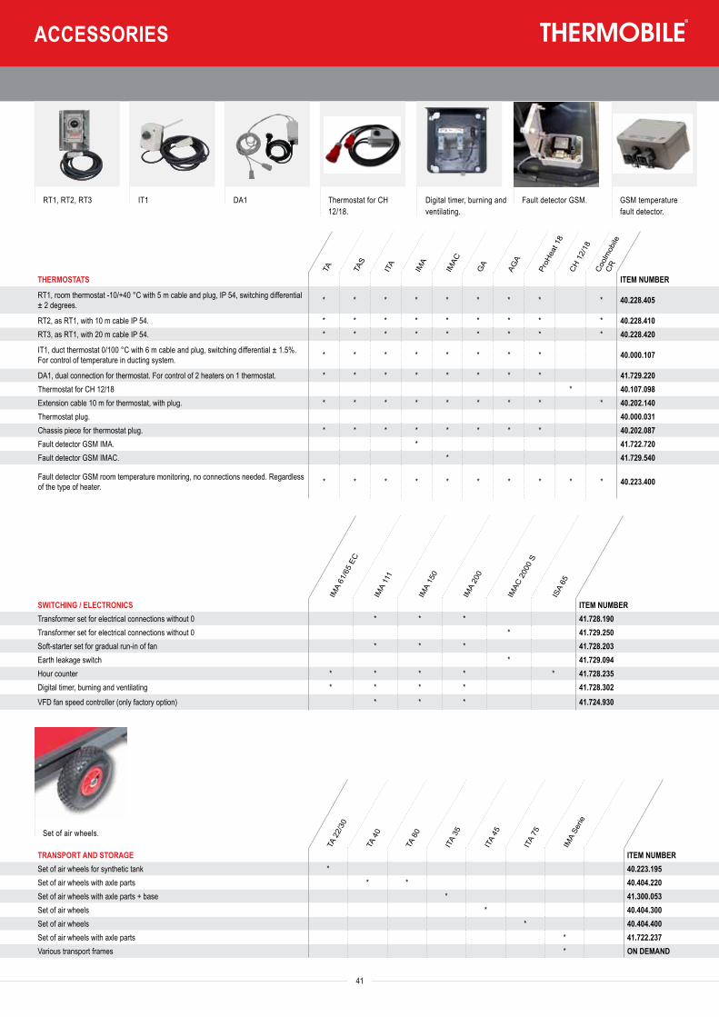
TECHNICAL SPECIFICATIONS | DIMENSIONS AND WEIGHTS
Powe
r (W
)
Ø (m
m)
RPM
Airfl
ow (m
3 /hr)
Powe
r con
sum
ptio
n
250
V/50
Hz
(AM
PS)
Air t
hrow
(m)
Noise
leve
l (dB
(A))
Num
ber o
f fan
sM
ax. m
ount
ing
heig
ht
(m)
Leng
th (m
m)
Wid
th (m
m)
Heig
ht (m
m)
Wei
ght (
kg)
MODEL ITEM NUMBERTTV 4500 230 420 1,400 4,500 1.1 45 60 1 - - - - - 50.500.210TTV 7000 390 518 1,400 7,000 1.8 55 64 1 - - - - - 50.500.220SDS 4 320 - 900 3,800 - - 41 1 5 688 650 400 18 50.500.400SDS 6 350 - 900 5,800 - - 48 1 7 600 650 400 21 50.500.410SDS 10 700 - 900 10,800 - - 51 2 10 650 1,200 400 36 50.500.420
41
TTV
4500
TTV
7000
OPTIONS ITEM NUMBERHose connection piece 450 mm * 50.500.211Hose connection piece 550 mm * 50.500.221Hose 450 mm, L=7.6 m * 50.500.212Hose 550 mm, L=7.6 m * 50.500.222
ACCESSORIES
RT1, RT2, RT3 IT1 DA1 Thermostat for CH 12/18.
Digital timer, burning and ventilating.
Fault detector GSM. GSM temperature fault detector.
Set of air wheels.
TA TAS
ITA
IMA
IMAC
GA
AGA
ProH
eat 1
8
CH 1
2/18
Cool
mob
ile
CR
IMA
61/6
5 EC
IMA
111
IMA
150
IMA
200
IMAC
200
0 S
ISA
65
TA 2
2/30
TA 4
0
TA 8
0
ITA
35
ITA
45
ITA
75
IMA
Serie
THERMOSTATS ITEM NUMBER
RT1, room thermostat -10/+40 °C with 5 m cable and plug, IP 54, switching differential ± 2 degrees. * * * * * * * * * 40.228.405
RT2, as RT1, with 10 m cable IP 54. * * * * * * * * * 40.228.410RT3, as RT1, with 20 m cable IP 54. * * * * * * * * * 40.228.420
IT1, duct thermostat 0/100 °C with 6 m cable and plug, switching differential ± 1.5%. For control of temperature in ducting system. * * * * * * * * 40.000.107
DA1, dual connection for thermostat. For control of 2 heaters on 1 thermostat. * * * * * * * * 41.729.220Thermostat for CH 12/18 * 40.107.098Extension cable 10 m for thermostat, with plug. * * * * * * * * * 40.202.140Thermostat plug. 40.000.031Chassis piece for thermostat plug. * * * * * * * * 40.202.087Fault detector GSM IMA. * 41.722.720Fault detector GSM IMAC. * 41.729.540
Fault detector GSM room temperature monitoring, no connections needed. Regardless of the type of heater. * * * * * * * * * * 40.223.400
SWITCHING / ELECTRONICS ITEM NUMBERTransformer set for electrical connections without 0 * * * 41.728.190Transformer set for electrical connections without 0 * 41.729.250Soft-starter set for gradual run-in of fan * * * 41.728.203Earth leakage switch * 41.729.094Hour counter * * * * * 41.728.235Digital timer, burning and ventilating * * * * 41.728.302VFD fan speed controller (only factory option) * * * 41.724.930
TRANSPORT AND STORAGE ITEM NUMBERSet of air wheels for synthetic tank * 40.223.195Set of air wheels with axle parts * * 40.404.220Set of air wheels with axle parts + base * 41.300.053Set of air wheels * 40.404.300Set of air wheels * 40.404.400Set of air wheels with axle parts * 41.722.237Various transport frames * ON DEMAND
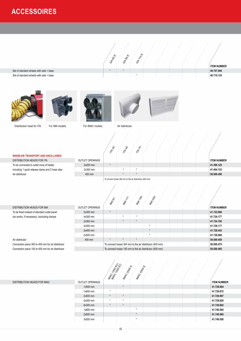
42
Distribution head for ITA. For IMA models. For IMAC models. Air distributor.
GA
60 E
GA
85 E
GA
110
E
ITA
35
ITA
45
ITA
75
IMA
61
IMA
111
IMA
150
IMA
200
IMAC
120
0 EC
/
IMAC
150
0 EC
IMAC
200
0 S
IMAC
400
0 E
ITEM NUMBERSet of standard wheels with axle + base * * 40.707.094Set of standard wheels with axle + base * 40.710.124
WARM AIR TRANSPORT AND ANCILLARIESDISTRIBUTION HEADS FOR ITA OUTLET OPENINGS ITEM NUMBERTo be connected to outlet cone of heater 2x200 mm * 41.300.125including 1 quick release clamp and 2 hose clips 2x300 mm * * 41.404.153Air distributor 400 mm * * 50.500.450
To connect hoses 300 mm to the air distributor (400 mm)
DISTRIBUTION HEADS FOR IMA OUTLET OPENINGS ITEM NUMBERTo be fixed instead of standard outlet panel 2x300 mm * 41.722.068(ex works, if necessary), excluding clamps 4x300 mm * * 41.724.177
2x360 mm * * 41.724.1924x300 mm * 41.728.1772x400 mm * 41.728.4432x500 mm * 41.728.068
Air distributor 400 mm * * * 50.500.450Connection piece 300 to 400 mm for air distributor To connect hoses 300 mm to the air distributor (400 mm) 50.500.475Connection piece 150 to 400 mm for air distributor To connect hoses 150 mm to the air distributor (400 mm) 50.500.465
DISTRIBUTION HEADS FOR IMAC OUTLET OPENINGS ITEM NUMBER1x500 mm * 41.729.8041x600 mm * 41.729.8722x500 mm * * 41.729.9974x300 mm * * 41.729.8206x300 mm * * 41.729.8621x800 mm * 41.740.5652x600 mm * 41.740.5603x500 mm * 41.740.050
ITA
35
ITA
45
ITA
75
ITA
45
ROBU
ST
ITA
75
ROBU
ST
ACCESSOIRES
Cool
mob
ile C
R 8
Cool
mob
ile C
R 17
/34
VTB
3000
VTB
9000
VTB
1500
0/18
000
ITA
35/C
H 12
-18
Verd
eelko
p IT
A 45
/75
ITA
45/7
5/IM
A 61
IMA
65/1
11/1
50/IM
AC
1200
/IMAC
150
0IM
A 20
0/IM
AC 2
000/
IMAC
400
0
Cool
mob
ile C
R 8
Cool
mob
ile C
R 17
/34
ITA
35
ITA
45/7
5/IM
A 61
Dist
r.hea
d IT
A 35
Dist
r.hea
d IT
A 45
/75
/ IM
A
61/1
11/1
50/2
00 /
IMAC
200
0
Dist
r.hea
d IM
A 11
1/15
0IS
A 65
/IMA
65/1
11/1
50/D
istr.
head
IMAC
200
0IM
A 20
0/IM
AC 2
000
IMAC
400
0 E
depe
ndin
g on
outle
t dia
m.
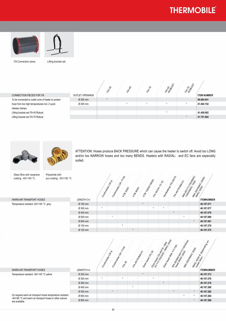
43
GA
60 E
GA
85 E
GA
110
E
ITA
35
ITA
45
ITA
75
IMA
61
IMA
111
IMA
150
IMA
200
IMAC
120
0 EC
/
IMAC
150
0 EC
IMAC
200
0 S
IMAC
400
0 E
ITEM NUMBERSet of standard wheels with axle + base * * 40.707.094Set of standard wheels with axle + base * 40.710.124
WARM AIR TRANSPORT AND ANCILLARIESDISTRIBUTION HEADS FOR ITA OUTLET OPENINGS ITEM NUMBERTo be connected to outlet cone of heater 2x200 mm * 41.300.125including 1 quick release clamp and 2 hose clips 2x300 mm * * 41.404.153Air distributor 400 mm * * 50.500.450
To connect hoses 300 mm to the air distributor (400 mm)
DISTRIBUTION HEADS FOR IMA OUTLET OPENINGS ITEM NUMBERTo be fixed instead of standard outlet panel 2x300 mm * 41.722.068(ex works, if necessary), excluding clamps 4x300 mm * * 41.724.177
2x360 mm * * 41.724.1924x300 mm * 41.728.1772x400 mm * 41.728.4432x500 mm * 41.728.068
Air distributor 400 mm * * * 50.500.450Connection piece 300 to 400 mm for air distributor To connect hoses 300 mm to the air distributor (400 mm) 50.500.475Connection piece 150 to 400 mm for air distributor To connect hoses 150 mm to the air distributor (400 mm) 50.500.465
DISTRIBUTION HEADS FOR IMAC OUTLET OPENINGS ITEM NUMBER1x500 mm * 41.729.8041x600 mm * 41.729.8722x500 mm * * 41.729.9974x300 mm * * 41.729.8206x300 mm * * 41.729.8621x800 mm * 41.740.5652x600 mm * 41.740.5603x500 mm * 41.740.050
Glass fibre with neoprene coating, -40/+140 °C.
Polyamide with pvc-coating, -30/+100 °C.
ATTENTION: Hoses produce BACK PRESSURE which can cause the heater to switch off. Avoid too LONG and/or too NARROW hoses and too many BENDS. Heaters with RADIAL- and EC fans are especially suited.
CONNECTION PIECES FOR ITA OUTLET OPENINGS ITEM NUMBERTo be connected to outlet cone of heater to protect Ø 300 mm * 99.084.041hose from too high temperatures incl. 2 quick Ø 400 mm * * * * 41.404.152release clamps.Lifting bracket set ITA 45 Robust * 41.450.002Lifting bracket set ITA 75 Robust * 41.751.002
ITA Connection piece. Lifting bracket set.
ITA
35
ITA
45
ITA
75
ITA
45
ROBU
ST
ITA
75
ROBU
ST
ACCESSOIRES
Cool
mob
ile C
R 8
Cool
mob
ile C
R 17
/34
VTB
3000
VTB
9000
VTB
1500
0/18
000
ITA
35/C
H 12
-18
Verd
eelko
p IT
A 45
/75
ITA
45/7
5/IM
A 61
IMA
65/1
11/1
50/IM
AC
1200
/IMAC
150
0IM
A 20
0/IM
AC 2
000/
IMAC
400
0WARM AIR TRANSPORT HOSES LENGTH 5 m ITEMNUMBERTemperature resistant -40/+140 °C grey Ø 150 mm * 40.107.071
Ø 300 mm * * * 40.107.077Ø 400 mm * 40.107.079Ø 500 mm * * 40.107.080Ø 600 mm * 40.107.081Ø 100 mm * 40.107.270Ø 120 mm * 40.107.275
Cool
mob
ile C
R 8
Cool
mob
ile C
R 17
/34
ITA
35
ITA
45/7
5/IM
A 61
Dist
r.hea
d IT
A 35
Dist
r.hea
d IT
A 45
/75
/ IM
A
61/1
11/1
50/2
00 /
IMAC
200
0
Dist
r.hea
d IM
A 11
1/15
0IS
A 65
/IMA
65/1
11/1
50/D
istr.
head
IMAC
200
0IM
A 20
0/IM
AC 2
000
IMAC
400
0 E
depe
ndin
g on
outle
t dia
m.
WARM AIR TRANSPORT HOSES LENGTH 6 m ITEMNUMBERTemperature resistant -30/+100 °C yellow Ø 200 mm * 40.107.273
Ø 300 mm * * * 40.107.276
On request warm air transport hoses temperature resistant -40/+80 °C and warm air transport hoses in other colours are available.
Ø 365 mm * 40.107.278Ø 400 mm * 40.107.280Ø 500 mm * * * 40.107.282Ø 600 mm * * 40.107.284Ø 800 mm * 40.107.286
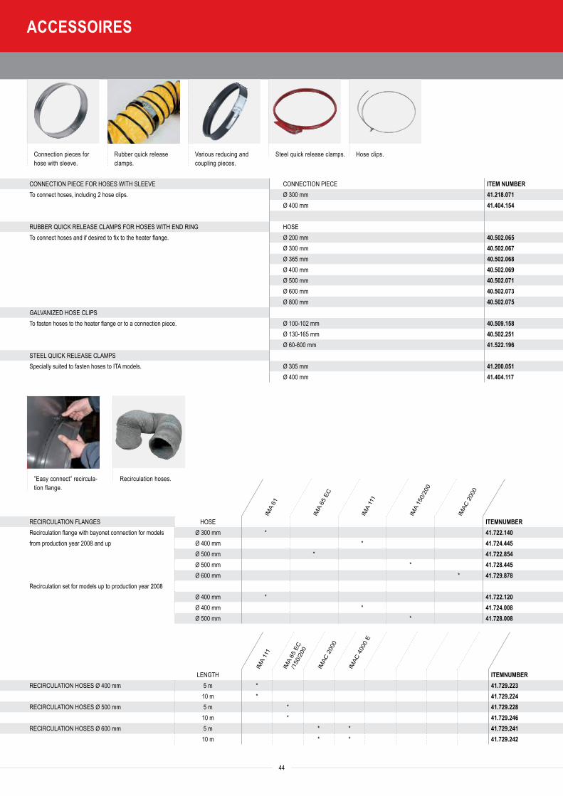
44
FRESH AIR SUCTION FLANGES ITEMNUMBERSuction flange for oil burner SL55 IMAC 2000 99.095.026
Connection pieces for hose with sleeve.
Rubber quick release clamps.
Various reducing and coupling pieces.
Steel quick release clamps. Hose clips.
”Easy connect” recircula-tion flange.
Recirculation hoses.
CONNECTION PIECE FOR HOSES WITH SLEEVE CONNECTION PIECE ITEM NUMBERTo connect hoses, including 2 hose clips. Ø 300 mm 41.218.071
Ø 400 mm 41.404.154
RUBBER QUICK RELEASE CLAMPS FOR HOSES WITH END RING HOSETo connect hoses and if desired to fix to the heater flange. Ø 200 mm 40.502.065
Ø 300 mm 40.502.067Ø 365 mm 40.502.068Ø 400 mm 40.502.069Ø 500 mm 40.502.071Ø 600 mm 40.502.073Ø 800 mm 40.502.075
GALVANIZED HOSE CLIPSTo fasten hoses to the heater flange or to a connection piece. Ø 100-102 mm 40.509.158
Ø 130-165 mm 40.502.251Ø 60-600 mm 41.522.196
STEEL QUICK RELEASE CLAMPSSpecially suited to fasten hoses to ITA models. Ø 305 mm 41.200.051
Ø 400 mm 41.404.117
IMA
61
IMA
65 E
C
IMA
111
IMA
150/
200
IMAC
200
0
RECIRCULATION FLANGES HOSE ITEMNUMBERRecirculation flange with bayonet connection for models Ø 300 mm * 41.722.140from production year 2008 and up Ø 400 mm * 41.724.445
Ø 500 mm * 41.722.854Ø 500 mm * 41.728.445Ø 600 mm * 41.729.878
Recirculation set for models up to production year 2008Ø 400 mm * 41.722.120Ø 400 mm * 41.724.008Ø 500 mm * 41.728.008
IMA
111
IMA
65 E
C /1
50/2
00
IMAC
200
0
IMAC
400
0 E
LENGTH ITEMNUMBERRECIRCULATION HOSES Ø 400 mm 5 m * 41.729.223
10 m * 41.729.224RECIRCULATION HOSES Ø 500 mm 5 m * 41.729.228
10 m * 41.729.246RECIRCULATION HOSES Ø 600 mm 5 m * * 41.729.241
10 m * * 41.729.242
TAS
800
E
GA
60/8
5/11
0 E
AGA
45/7
5/10
2/11
1 E
STAINLESS STEEL WALL CONNECTOR WITH RAINCAP DIAMETER ITEM NUMBERPrevents raining in and back pressure Ø 100 mm * * * 40.721.016
AGA
45/7
5/10
2/11
1 E
GA
60/8
5/11
0 E
TAS
800
E
SUCTION OF FRESH AIRFRESH AIR SUCTION HOSES 5 m DIAMETER ITEM NUMBERFor suction of clean fresh air Ø 102 mm * * * 41.000.585
ITA
35
IMA
61/ I
TA 4
5/75
IMA
65 E
C/11
1/15
0IM
AC 2
000
/ 220
0 Di
str.
head
300
IMAC
200
0 / 2
200
Dist
r.
head
500
IMAC
400
0 Di
str.h
ead
500
Cool
mob
ile C
R 8
Cool
mob
ile C
R 17
/34
ACCESSOIRES
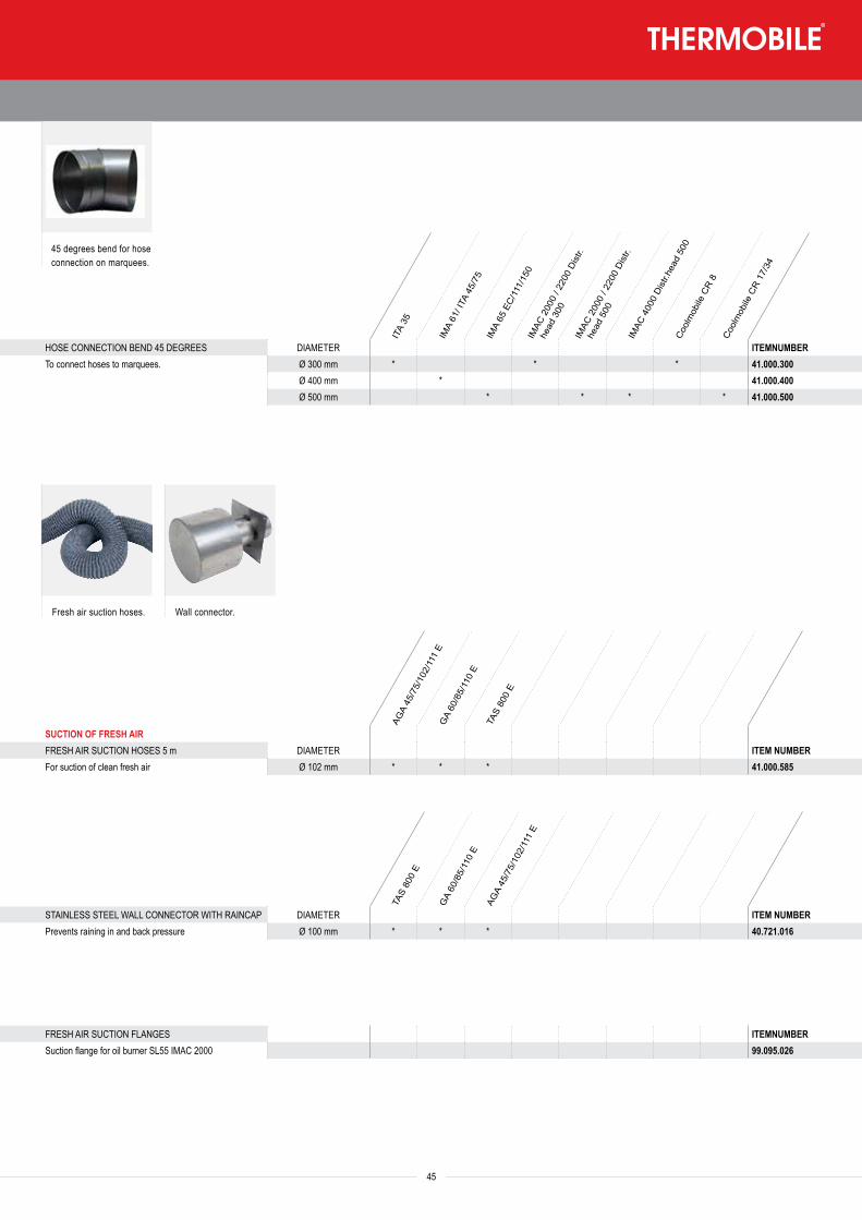
45
FRESH AIR SUCTION FLANGES ITEMNUMBERSuction flange for oil burner SL55 IMAC 2000 99.095.026
IMA
61
IMA
65 E
C
IMA
111
IMA
150/
200
IMAC
200
0
IMA
111
IMA
65 E
C /1
50/2
00
IMAC
200
0
IMAC
400
0 E
LENGTH ITEMNUMBERRECIRCULATION HOSES Ø 400 mm 5 m * 41.729.223
10 m * 41.729.224RECIRCULATION HOSES Ø 500 mm 5 m * 41.729.228
10 m * 41.729.246RECIRCULATION HOSES Ø 600 mm 5 m * * 41.729.241
10 m * * 41.729.242
Fresh air suction hoses. Wall connector.
TAS
800
E
GA
60/8
5/11
0 E
AGA
45/7
5/10
2/11
1 E
STAINLESS STEEL WALL CONNECTOR WITH RAINCAP DIAMETER ITEM NUMBERPrevents raining in and back pressure Ø 100 mm * * * 40.721.016
AGA
45/7
5/10
2/11
1 E
GA
60/8
5/11
0 E
TAS
800
E
SUCTION OF FRESH AIRFRESH AIR SUCTION HOSES 5 m DIAMETER ITEM NUMBERFor suction of clean fresh air Ø 102 mm * * * 41.000.585
ITA
35
IMA
61/ I
TA 4
5/75
IMA
65 E
C/11
1/15
0IM
AC 2
000
/ 220
0 Di
str.
head
300
IMAC
200
0 / 2
200
Dist
r.
head
500
IMAC
400
0 Di
str.h
ead
500
Cool
mob
ile C
R 8
Cool
mob
ile C
R 17
/34
HOSE CONNECTION BEND 45 DEGREES DIAMETER ITEMNUMBERTo connect hoses to marquees. Ø 300 mm * * * 41.000.300
Ø 400 mm * 41.000.400Ø 500 mm * * * * 41.000.500
45 degrees bend for hose connection on marquees.
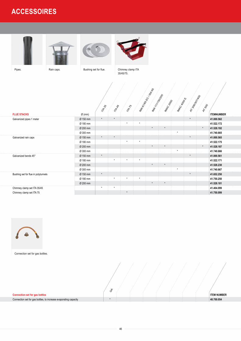
SERVICE TESTING EQUIPMENT ITEM NUMBERPressure gauge 0-25 bar 1/8” BSP 40.000.185Pressure gauge 0-25 bar 1/4” BSP, glycerine filled 40.000.332Valve 1/8” outer X 1/4” inner 40.000.349Pressure gauge 0-0.6 bar 40.225.146Soot pump, complete with paper and lubricant 40.000.190Testing paper for soot pump 40.000.189Filling liquid for CO2-meter 40.000.191Testing unit for oil heaters with SATRONIC oil burner relays UP 711 On demand 40.223.101Testing unit for oil heaters with SATRONIC gas burner relays UP 712 On demand 40.000.330Smokegas thermometer 40.000.192Spray can with paint, colour red, content 400 ml 60.530.075Spray can with paint, colour anthracite, content 400 ml 60.530.077
T TA ITA
ISA
65/IM
A 61
/65
ECIM
A 11
1/15
0/20
0 /
IMAC
200
0/40
00TA
S 80
0
Fuel accessories ITEMNUMBER
Conversion kit from 1-way to 2-way pipe system, for suction from bulk tank, maximum length 50 m/height 3 m (depends on diameter of pipe). To be mounted on fuel pump. * * * 41.402.114
Oil supply unit DE 600, 60 litre to transport oil under pressure form bulk tank to one or more heaters, to maximum height of 30 m. * * * * * * 41.530.005
Needed per heater: connection/reduction set with magnetic valve * * * * * * 41.522.213Oil preheating with cable (for SL 22) * 41.527.212Oil preheating with cable (for SL 44/SL 55) * 41.527.211Oil filter with water separation and bracket for return pipe * * 41.722.230Oil filter with water separation, interchangeble with current filter * 40.467.052Oil filter set with preheating * * 41.722.370Oil suction set universal * * 41.520.104
46
ITA
35
ITA
45
ITA
75
IMA
61/6
5 EC
/ IS
A 65
IMA
111/
150/
200
IMAC
200
0
IMAC
400
0 E
AT 3
06/3
07/4
00AT
500
FLUE STACKS Ø (mm) ITEMNUMBERGalvanized pipes 1 meter Ø 150 mm * * * 41.000.562
Ø 180 mm * * 41.522.172Ø 200 mm * * * 41.528.192Ø 300 mm * 41.740.665
Galvanized rain caps Ø 150 mm * * * 41.000.565Ø 180 mm * * 41.522.175Ø 200 mm * * * 41.528.187Ø 300 mm * 41.740.666
Galvanized bends 45° Ø 150 mm * * 41.000.561Ø 180 mm * * * 41.522.171Ø 200 mm * * 41.528.230Ø 300 mm * 41.740.667
Bushing set for flue in polytunnels Ø 150 mm * * 41.652.250Ø 180 mm * * * 41.750.250Ø 200 mm * * 41.528.181
Chimney clamp set ITA 35/45 * * 41.404.099Chimney clamp set ITA 75 * 41.750.099
Pipes. Rain caps. Bushing set for flue. Chimney clamp ITA 35/45/75.
Connection set for gas bottles.
GA
Connection set for gas bottles ITEM NUMBERConnection set for gas bottles, to increase evaporating capacity * 40.700.054
ACCESSOIRES
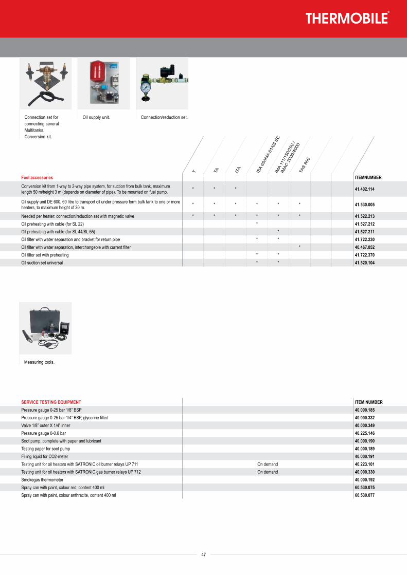
SERVICE TESTING EQUIPMENT ITEM NUMBERPressure gauge 0-25 bar 1/8” BSP 40.000.185Pressure gauge 0-25 bar 1/4” BSP, glycerine filled 40.000.332Valve 1/8” outer X 1/4” inner 40.000.349Pressure gauge 0-0.6 bar 40.225.146Soot pump, complete with paper and lubricant 40.000.190Testing paper for soot pump 40.000.189Filling liquid for CO2-meter 40.000.191Testing unit for oil heaters with SATRONIC oil burner relays UP 711 On demand 40.223.101Testing unit for oil heaters with SATRONIC gas burner relays UP 712 On demand 40.000.330Smokegas thermometer 40.000.192Spray can with paint, colour red, content 400 ml 60.530.075Spray can with paint, colour anthracite, content 400 ml 60.530.077
Connection set for connecting several Multitanks.Conversion kit.
Oil supply unit. Connection/reduction set.
T TA ITA
ISA
65/IM
A 61
/65
ECIM
A 11
1/15
0/20
0 /
IMAC
200
0/40
00TA
S 80
0
Fuel accessories ITEMNUMBER
Conversion kit from 1-way to 2-way pipe system, for suction from bulk tank, maximum length 50 m/height 3 m (depends on diameter of pipe). To be mounted on fuel pump. * * * 41.402.114
Oil supply unit DE 600, 60 litre to transport oil under pressure form bulk tank to one or more heaters, to maximum height of 30 m. * * * * * * 41.530.005
Needed per heater: connection/reduction set with magnetic valve * * * * * * 41.522.213Oil preheating with cable (for SL 22) * 41.527.212Oil preheating with cable (for SL 44/SL 55) * 41.527.211Oil filter with water separation and bracket for return pipe * * 41.722.230Oil filter with water separation, interchangeble with current filter * 40.467.052Oil filter set with preheating * * 41.722.370Oil suction set universal * * 41.520.104
47
ITA
35
ITA
45
ITA
75
IMA
61/6
5 EC
/ IS
A 65
IMA
111/
150/
200
IMAC
200
0
IMAC
400
0 E
AT 3
06/3
07/4
00AT
500
FLUE STACKS Ø (mm) ITEMNUMBERGalvanized pipes 1 meter Ø 150 mm * * * 41.000.562
Ø 180 mm * * 41.522.172Ø 200 mm * * * 41.528.192Ø 300 mm * 41.740.665
Galvanized rain caps Ø 150 mm * * * 41.000.565Ø 180 mm * * 41.522.175Ø 200 mm * * * 41.528.187Ø 300 mm * 41.740.666
Galvanized bends 45° Ø 150 mm * * 41.000.561Ø 180 mm * * * 41.522.171Ø 200 mm * * 41.528.230Ø 300 mm * 41.740.667
Bushing set for flue in polytunnels Ø 150 mm * * 41.652.250Ø 180 mm * * * 41.750.250Ø 200 mm * * 41.528.181
Chimney clamp set ITA 35/45 * * 41.404.099Chimney clamp set ITA 75 * 41.750.099
GA
Connection set for gas bottles ITEM NUMBERConnection set for gas bottles, to increase evaporating capacity * 40.700.054
Measuring tools.
ACCESSOIRES
THERMOBILE INDUSTRIES BVKonijnenberg 804825 BD Breda Netherlands
Postbus 33124800 DH Breda Netherlands Bedrijfsnummer: 3502
T +31 (0)76 587 34 50 F +31 (0)76 587 27 [email protected]
THERMOBILE UK LTD12, Buckingham CloseBermuda Industrial EstateNuneaton, WarwickshireCV10 7JT Great-Britain
T +44 (0)2476 35 79 60F +44 (0)2476 35 79 [email protected] www.thermobile.co.uk
THERMOBILE FRANCE sarl3, rue Denis Papin45240 LA FERTÉ ST. AUBIN France
T +33 (0)2 38 76 59 25F +33 (0)2 38 76 58 [email protected] www.thermobile.fr
08 - 2016