Embed Size (px)
Citation preview

PROCEEDINGS OF SPIE
SPIEDigitalLibrary.org/conference-proceedings-of-spie
Front Matter: Volume 7399
, "Front Matter: Volume 7399," Proc. SPIE 7399, Carbon Nanotubes,Graphene, and Associated Devices II, 739901 (9 September 2009); doi:10.1117/12.844832
Event: SPIE NanoScience + Engineering, 2009, San Diego, California, UnitedStates
Downloaded From: https://www.spiedigitallibrary.org/conference-proceedings-of-spie on 2/3/2019 Terms of Use: https://www.spiedigitallibrary.org/terms-of-use

PROCEEDINGS OF SPIE
Volume 7399
Proceedings of SPIE, 0277-786X, v. 7399
SPIE is an international society advancing an interdisciplinary approach to the science and application of light.
Carbon Nanotubes, Graphene, and Associated Devices II
Manijeh Razeghi Didier Pribat Young-Hee Lee Editors 5–6 August 2009 San Diego, California, United States Sponsored and Published by SPIE
Downloaded From: https://www.spiedigitallibrary.org/conference-proceedings-of-spie on 2/3/2019Terms of Use: https://www.spiedigitallibrary.org/terms-of-use
The papers included in this volume were part of the technical conference cited on the cover and title page. Papers were selected and subject to review by the editors and conference program committee. Some conference presentations may not be available for publication. The papers published in these proceedings reflect the work and thoughts of the authors and are published herein as submitted. The publisher is not responsible for the validity of the information or for any outcomes resulting from reliance thereon. Please use the following format to cite material from this book: Author(s), "Title of Paper," in Carbon Nanotubes, Graphene, and Associated Devices II, edited by Manijeh Razeghi, Didier Pribat, Young-Hee Lee, Proceedings of SPIE Vol. 7399 (SPIE, Bellingham, WA, 2009) Article CID Number. ISSN 0277-786X ISBN 9780819476890 Published by SPIE P.O. Box 10, Bellingham, Washington 98227-0010 USA Telephone +1 360 676 3290 (Pacific Time)· Fax +1 360 647 1445 SPIE.org Copyright © 2009, Society of Photo-Optical Instrumentation Engineers Copying of material in this book for internal or personal use, or for the internal or personal use of specific clients, beyond the fair use provisions granted by the U.S. Copyright Law is authorized by SPIE subject to payment of copying fees. The Transactional Reporting Service base fee for this volume is $18.00 per article (or portion thereof), which should be paid directly to the Copyright Clearance Center (CCC), 222 Rosewood Drive, Danvers, MA 01923. Payment may also be made electronically through CCC Online at copyright.com. Other copying for republication, resale, advertising or promotion, or any form of systematic or multiple reproduction of any material in this book is prohibited except with permission in writing from the publisher. The CCC fee code is 0277-786X/09/$18.00. Printed in the United States of America. Publication of record for individual papers is online in the SPIE Digital Library.
SPIEDigitalLibrary.org
Paper Numbering: Proceedings of SPIE follow an e-First publication model, with papers published first online and then in print and on CD-ROM. Papers are published as they are submitted and meet publication criteria. A unique, consistent, permanent citation identifier (CID) number is assigned to each article at the time of the first publication. Utilization of CIDs allows articles to be fully citable as soon they are published online, and connects the same identifier to all online, print, and electronic versions of the publication. SPIE uses a six-digit CID article numbering system in which:
The first four digits correspond to the SPIE volume number. The last two digits indicate publication order within the volume using a Base 36 numbering
system employing both numerals and letters. These two-number sets start with 00, 01, 02, 03, 04, 05, 06, 07, 08, 09, 0A, 0B … 0Z, followed by 10-1Z, 20-2Z, etc.
The CID number appears on each page of the manuscript. The complete citation is used on the first page, and an abbreviated version on subsequent pages. Numbers in the index correspond to the last two digits of the six-digit CID number.
Downloaded From: https://www.spiedigitallibrary.org/conference-proceedings-of-spie on 2/3/2019Terms of Use: https://www.spiedigitallibrary.org/terms-of-use

Contents
v Conference Committee vii Sub-nanometer resolution for the inspection of reflective surfaces using white light (Plenary
Paper) [7405-37] W. Jüptner, T. Bothe, Bremer Institut für angewandte Strahltechnik (Germany) CARBON NANOTUBE SYNTHESIS 7399 04 Study on the effects of hydrogen pretreatment on nickel catalyst used for multi walled
carbon nanotube growth [7399-03] M. Kossler, B. L. Crossley, R. A. Coutu, Jr., L. A. Starman, P. J. Collins, Air Force Institute of
Technology (United States) 7399 05 Synthesis of MWCNTs using CVD without metallic catalysts [7399-04] H.-W. Chen, H.-L. Ma, National Sun Yat-Sen Univ. (Taiwan); J.-H. Lin, National Univ. of Tainan
(Taiwan) CARBON NANOTUBE DEVICES I 7399 06 Multifunctional logic circuit using ambipolar carbon nanotube transistor (Invited Paper)
[7399-05] W. J. Yu, Sungkyunkwan Univ. (Korea, Republic of); U. J. Kim, Samsung Advanced Institute of
Technology (Korea, Republic of); B. R. Kang, I. H. Lee, Sungkyunkwan Univ. (Korea, Republic of); E. H. Lee, Samsung Advanced Institute of Technology (Korea, Republic of); Y. H. Lee, Sungkyunkwan Univ. (Korea, Republic of)
7399 07 Pool-Frenkel emission and hopping conduction in semiconducting carbon nanotube
transistor (Invited Paper) [7399-06] D. Perello, Univ. of Pittsburgh (United States); W. Yu, D. J. Bae, S. J. Chae, Sungkyunkwan
Univ. (Korea, Republic of); M. J. Kim, The Univ. of Texas at Dallas (United States); Y. H. Lee, Sungkyunkwan Univ. (Korea, Republic of); M. Yun, Univ. of Pittsburgh (United States)
7399 09 High performances CNTFETs achieved using CNT networks for selective gas sensing
[7399-08] L. Gorintin, P. Bondavalli, P. Legagneux, Thales Research & Technology (France); D. Pribat,
LPICM, Ecole Polytechnique (France) SORTING AND CHARACTERIZATION OF SINGLE-WALL NANOTUBES I 7399 0B Highly concentrated diameter selective nanodispersion of single-walled carbon nanotubes
in water [7399-11] C. Biswas, K. K. Kim, H.-Z. Geng, H. K. Park, S. C. Lim, S. J. Chae, S. M. Kim, Y. H. Lee,
Sungkyunkwan Univ. (Korea, Republic of); M. Nayhouse, M. Yun, Univ. of Pittsburgh (United States)
iii
Downloaded From: https://www.spiedigitallibrary.org/conference-proceedings-of-spie on 2/3/2019Terms of Use: https://www.spiedigitallibrary.org/terms-of-use
CARBON NANOTUBE DEVICES II 7399 0F Thermal Moore's law and near-field thermal conductance in carbon-based electronics
(Invited Paper) [7399-15] S. V. Rotkin, Lehigh Univ. (United States) CARBON NANOTUBE DEVICES III 7399 0M Stabilizing a pulsed field emission from an array of carbon nanotubes [7399-22] D. Roy Mahapatra, S. Anand, Indian Institute of Science (India); N. Sinha, Massachusetts
Institute of Technology (United States); R. V. N. Melnik, Wilfrid Laurier Univ. (Canada) GRAPHENE II 7399 0T Growth of graphene films by plasma enhanced chemical vapour deposition [7399-29] L. Baraton, NanoMade, LPICM, Ecole Polytechnique (France); L. Gangloff, S. Xavier, THALES,
TRT/Nanocarb (France); C. S. Cojocaru, NanoMade, LPICM, Ecole Polytechnique (France); V. Huc, Univ. Paris-Sud XI (France); P. Legagneux, THALES, TRT/Nanocarb (France); Y. H. Lee, Sungkyunkwan Univ. (Korea, Republic of); D. Pribat, NanoMade, LPICM, Ecole Polytechnique (France)
POSTER SESSION 7399 0V Single-walled carbon nanotubes forests as demonstration for nanotubes length controlling
[7399-30] F. Lamberti, M. Meneghetti, Univ. of Padova (Italy); N. Elvassore, Univ. of Padova (Italy) and
Venetian Institute of Molecular Medicine (Italy) 7399 0W Synthesis of large-area graphene layers on nickel film by chemical vapor deposition:
wrinkle formation [7399-32] S. J. Chae, F. Güneş, K. K. Kim, E. S. Kim, G. H. Han, S. M. Kim, Sungkyunkwan Univ. (Korea,
Republic of); H.-J. Shin, Univ. (Korea, Republic of) and Samsung Advanced Institute of Technology (Korea, Republic of); S.-M. Yoon, J.-Y. Choi, Samsung Advanced Institute of Technology (Korea, Republic of); M. H. Park, C. W. Yang, Sungkyunkwan Univ. (Korea, Republic of); D. Pribat, Lab. de Physique des Interfaces et des Couches Minces, CNRS, Ecole Polytechnique (France); Y. H. Lee, Sungkyunkwan Univ. (Korea, Republic of)
7399 0Y Carbon nanotube vee dipole antennas for optical applications (Invited Paper) [7399-35] H. R. Khaleel, H. M. Al-Rizzo, T. A. Elwi, D. Rucker, Univ. of Arkansas at Little Rock (United
States) Author Index
iv
Downloaded From: https://www.spiedigitallibrary.org/conference-proceedings-of-spie on 2/3/2019Terms of Use: https://www.spiedigitallibrary.org/terms-of-use

Conference Committee
Symposium Chairs
David L. Andrews, University of East Anglia Norwich (United Kingdom) James G. Grote, Air Force Research Laboratory (United States)
Conference Chairs
Manijeh Razeghi, Northwestern University (United States) Didier Pribat, Ecole Polytechnique (France) Young-Hee Lee, Sungkyunkwan University (Korea, Republic of)
Program Committee
Phaedon Avouris, IBM Thomas J. Watson Research Center (United States)
Ray H. Baughman, The University of Texas at Dallas (United States) Jean-Philippe Bourgoin, Commissariat à l'Energie Atomique (France) Manish Chhowalla, Rutgers University (United States) Hongjie Dai, Stanford University (United States) Nicole Grobert, University of Oxford (United Kingdom) Kenji Hata, National Institute of Advanced Industrial Science and
Technology (Japan) Mark C. Hersam, Northwestern University (United States) Ali Javey, University of California, Berkeley (United States) Seung Hee Lee, Chonbuk National University (Korea, Republic of) Pierre Legagneux, Thales Research & Technology (France) Annick Loiseau, ONERA (France) Ryan P. McClintock, Northwestern University (United States) William I. Milne, University of Cambridge (United Kingdom) Philip W. T. Pong, The University of Hong Kong (Hong Kong, China) John A. Rogers, University of Illinois at Urbana-Champaign (United
States) Siegmar Roth, Max-Planck-Institut für Festkörperforschung (Germany) Donald J. Silversmith, Air Force Office of Scientific Research (United
States) Jin Zhang, Peking University (China)
Session Chairs
1 Carbon Nanotube Synthesis Laurent Baraton, Ecole Polytechnique (France)
v
Downloaded From: https://www.spiedigitallibrary.org/conference-proceedings-of-spie on 2/3/2019Terms of Use: https://www.spiedigitallibrary.org/terms-of-use

2 Carbon Nanotube Devices I Andrea C. Ferrari, University of Cambridge (United Kingdom)
3 Sorting and Characterization of Single-wall Nanotubes I Chang-Soo Han, Korea Institute of Machinery & Materials (Korea, Republic of)
4 Graphene I Jing Kong, Massachusetts Institute of Technology (United States)
5 Carbon Nanotube Devices II Young-Hee Lee, Sungkyunkwan University (Korea, Republic of)
6 Carbon Nanotube Devices III Louis Gorintin, Thales Research & Technology (France)
7 Sorting and Characterization of Single-wall Nanotubes II Mark C. Hersam, Northwestern University (United States)
8 Graphene II Young-Hee Lee, Sungkyunkwan University (Korea, Republic of)
vi
Downloaded From: https://www.spiedigitallibrary.org/conference-proceedings-of-spie on 2/3/2019Terms of Use: https://www.spiedigitallibrary.org/terms-of-use
Sub-Nanometer Resolution for the Inspection of Reflective Surfaces Using White Light
Werner Jüptner, Thorsten Bothe
c/o BIAS, Klagenfurter Str. 2, D-27721 Bremen, Germany
ABSTRACT
The quality control of highly reflective surfaces requires a measurement method which is able to resolve the surface shape in the nanometer range. Different methods have been developed in the past, e.g. based on interferometry or by tactile coordinate measurement machines. However, most of them do not match the industrial need for a fast method which is insensitive to environmental disturbance.
The newly developed method using the reflection of fringe pattern by the surface under test, and therefore called “Fringe Reflection Technique (FRT)”, overcomes the difficulties of known measurement methods. In this method a pattern of straight fringes is generated by a monitor. The mirrored pattern is observed by a camera via the object surface under test. Any deviation of the surface against the ideal, i.e. the mathematically accurate surface will yield a distortion of the pattern. This distortion is analyzed by an image processing system, called the Fringe Processor. The surface topology is delivered by local surface gradients which can be integrated to object shape or differentiated to local curvature. The resolution of the system can be adapted to the measurement requirements in a wide range from micrometer down to sub-nanometer. Anyhow, the system is stable against environmental disturbances. It works without vibration isolation in rooms without any climate control. It is possible to measure freeform surfaces with no constraints on object geometry.
The measurement of a silicon mirror surface produced by diamond turning in a high precision tool machine serves as one example. The surface shape could be determined with a resolution below one nanometer. The measurements match the results of an interferometer and are better in certain areas.
Keywords: Shape, reflectometry, white light, nanometer resolution, topometry, freeform
1. INTRODUCTION Shape measurements with a resolution down into the nanometer range are getting an increasingly importance [1], not only for the micro- and nano-system production but for standard products like coatings on cars or mirrors. Different metrology technologies have been developed in the past like phase sensitive microscopy, confocal microscopy, atomic force microscopy, or scanning near field optical microscopy [2]. The majority of these high resolution technologies are based on a point wise acquisition of the data and a scanning system for the determination of the whole surface topology. Furthermore, the methods are mostly sensitive to environmental disturbance.
The Fringe Reflection Technology (FRT) [3] is a whole field measurement technique using the imaging of fringes via the object surface: A fringe system displayed by a monitor is observed after the reflection by the object surface. Any tilt of the object surface changes the angle of reflection. This yields in a displacement of the fringe system to be measured by means of an image processing system. The displacement is strongly related to the angle of the surface against the bisector of the angle between camera normal and monitor normal. If this is the angle of a local part of the surface then it can be indicated as the surface gradient at this point, i.e. the FRT provides primarily the gradient field of the surface shape. By integration, the shape can be evaluated down to nanometers [4]. The FRT enables the characterization of reflective – not even specular – surfaces which cannot be measured by means of standard optical or tactile methods.
The basics of the FRT are described in the first part of this paper. The method can be used in a number of adapted set-ups. But in principle a monitor with software generated sinusoidal fringes and a CCD camera with an image processing system is needed. The nest point is the description of the data generation and the resolution that can be achieved depending on the parameters of the system.
Three examples of application will be described in order to demonstrate the wide variety of possible measurements with high resolution.
Plenary Paper
Instrumentation, Metrology, and Standards for Nanomanufacturing III, edited by Michael T. Postek, John A. Allgair,Proc. of SPIE Vol. 7405, 740502 · © 2009 SPIE · CCC code: 0277-786X/09/$18 · doi: 10.1117/12.838373
Proc. of SPIE Vol. 7405 740502-1
vii
Downloaded From: https://www.spiedigitallibrary.org/conference-proceedings-of-spie on 2/3/2019Terms of Use: https://www.spiedigitallibrary.org/terms-of-use

2. FUNDAMENTALS OF THE FRINGE REFLECTION TECHNIQUE 2.1 Principle of the FRT and the Set-up
The basic set-up of a fringe reflection set-up comprises three hardware components, Fig.1:
- a monitor to display parallel sinusoidal fringes, - a CCD camera as a part of an image processing system, and - the object under investigation.
The camera on top of the monitor, Fig.1a, observes the fringe system via the object under investigation via the test object, in this case a car front window, Fig.1b left. The object is reflective by condition of the method, i.e. the fringe system is visible even when the surface is only partly specular. The camera is focused onto the surface of the object, Fig.1c. This results in a blurred image of the fringe system. However, a sinusoidal fringe remains sinusoidal under blurred conditions, too. A flat mirror would cause an undistorted image of the fringe system. Any tilt of the surface or a part of it displaces the related fringe system. A curved object will deform the former straight parallel fringe system according to the local angle of the surface against the normal or in other terms according to the surface gradient. The reflected fringe system is measured using a phase shifting method [5] and evaluated by means of an image processing system [6].
a) b) c)
Fig. 1. System components: a) monitor displaying the fringe system and a CCD camera fixed on top of the monitor (dash line circle), b) car window (test object) at the left and monitor from back side at the right, c) schematic sketch
2.2 Geometrical Model and Evaluation
The evaluation will be derived on a geometrical model neglecting the scattered part of the light coming from the object, Fig.2. A surface angle of Δα/2 against the normal yields a deflection of the reflected image by an angle α according to the laws of optics and by this a displacement of Δs of the imaged fringe system on the target in the distance l from the
a) b)
Fig. 2. Evaluation model: a) geometrical relations of fringe displacement, b) gradient and displacement angle
object. The deflection is caused by a local gradient of the surface Δα/2 – the same as above – which is given by the change of height Δz between two neighbored points of the surface in a distance of xcam. The relations between the geometrical quantities are given by:
Proc. of SPIE Vol. 7405 740502-2
viii
Downloaded From: https://www.spiedigitallibrary.org/conference-proceedings-of-spie on 2/3/2019Terms of Use: https://www.spiedigitallibrary.org/terms-of-use

lsΔ
=αtan (1)
camxzΔ
=2
tan α (2)
and: camxlsz
2Δ
≈Δ (3)
In this equation xcam, - the size of an “object point” on the target - is given by the linear dimension of the object divided by the pixel number. The distance l is a measurable parameter of the set-up. The displacement of the fringe system – or the regarded part of it – has to be determined by image processing. Since the displacement shifts the fringe system by parts of the period the local phase of the fringes must be measured. For this, phase shifting technique is the state of the art [5]. In order to evaluate the minimum phase shift to be resolved in a given set-up one has to take into account the imaging system, Fig.3. The distance l from the camera to the object is the same as the distance from the monitor to the object assuming that the camera is fixed on the monitor or close to it. It can be derived by the geometrical relations:
surface
l Fig. 3. Geometrical model of the imaging: the circle of confusion has identical aperture size in double focus distance
πϕ
πϕ
22Δ
=ΔΔ
=Δ PsorPs
(4)
with Δs: smallest displacement to be measured P: smallest possible period of the fringe system Δϕ: smallest phase change to be measured 2 π: full fringe angle
The geometry of the set-up yields the equality d = P, Fig.3. With the focal length f and the f-number k the size of d is
kfd = (5)
Equ.(5) together with Equ.(4) leads to
πϕ
2Δ
=Δkfs (6)
Combining Equ.(6) with Equ.(3) results in
πϕ
221 Δ
=Δkl
fxz cam (7)
xcam is the distance between two neighbored object points; f/l is the reduction of the object size by the imaging. The product of xcam and the reduction is the distance of two neighbored points on the target which is the size of a camera pixel. Δϕ/2π is the smallest resolvable phase change. Taking these relations into account results in equation for the height resolution Δz as a function of the camera pixel size pixel, the aperture k and the phase resolution Δϕ/2π:
πϕ
221 Δ
=Δk
pixelz (8)
There are three parameters in this equation that influence the resolution:
Proc. of SPIE Vol. 7405 740502-3
ix
Downloaded From: https://www.spiedigitallibrary.org/conference-proceedings-of-spie on 2/3/2019Terms of Use: https://www.spiedigitallibrary.org/terms-of-use
- The camera pixel size pixel is given by the available targets and is approximately 10 µm for a common camera. - The aperture k of the imaging objective which is close to 10. This value cannot be extended very much since a smaller
aperture yields less light and by this more noise in the camera signal. - The resolvable phase change which is normally expected to be 1/100 in phase shifting. However, this value can be
improved up to about 1/1000.
Inserting the following values: Δz=10 μm, k=16, Δϕ=2π/1000 Equ.(8) results in the height resolution of Δz=0.63 nm
2.3 Hierarchical Phase Shifting
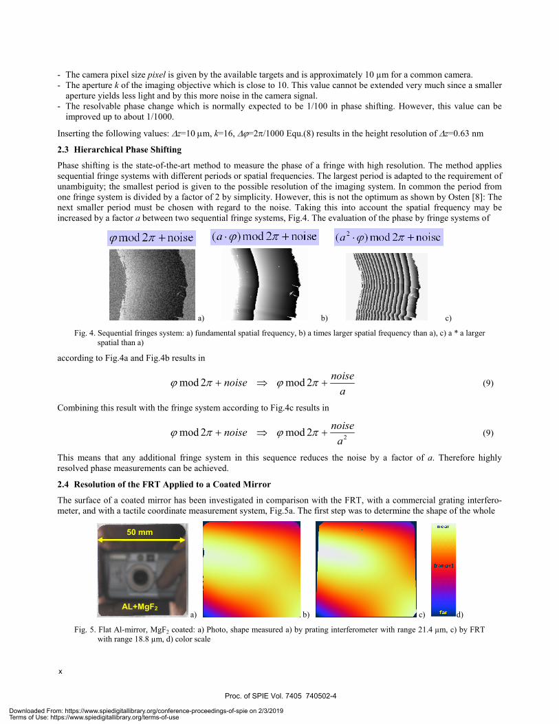
Phase shifting is the state-of-the-art method to measure the phase of a fringe with high resolution. The method applies sequential fringe systems with different periods or spatial frequencies. The largest period is adapted to the requirement of unambiguity; the smallest period is given to the possible resolution of the imaging system. In common the period from one fringe system is divided by a factor of 2 by simplicity. However, this is not the optimum as shown by Osten [8]: The next smaller period must be chosen with regard to the noise. Taking this into account the spatial frequency may be increased by a factor a between two sequential fringe systems, Fig.4. The evaluation of the phase by fringe systems of
a) b) c)
Fig. 4. Sequential fringes system: a) fundamental spatial frequency, b) a times larger spatial frequency than a), c) a * a larger spatial than a)
according to Fig.4a and Fig.4b results in
a
noisenoise +⇒+ πϕπϕ 2mod2mod (9)
Combining this result with the fringe system according to Fig.4c results in
22mod2moda
noisenoise +⇒+ πϕπϕ (9)
This means that any additional fringe system in this sequence reduces the noise by a factor of a. Therefore highly resolved phase measurements can be achieved.
2.4 Resolution of the FRT Applied to a Coated Mirror
The surface of a coated mirror has been investigated in comparison with the FRT, with a commercial grating interfero-meter, and with a tactile coordinate measurement system, Fig.5a. The first step was to determine the shape of the whole
a) b) c) d)
Fig. 5. Flat Al-mirror, MgF2 coated: a) Photo, shape measured a) by prating interferometer with range 21.4 µm, c) by FRT with range 18.8 µm, d) color scale
AL+MgF2
50 mm
Proc. of SPIE Vol. 7405 740502-4
x
Downloaded From: https://www.spiedigitallibrary.org/conference-proceedings-of-spie on 2/3/2019Terms of Use: https://www.spiedigitallibrary.org/terms-of-use

mirror by means of a commercial grating interferometer (by Zygo), Fig.5b) and by the fringe reflection technique, Fig.5c. The measurements showed a nearly cylindrical shape with a diagonal “hill” in the middle. The peak-to-valley value of the contour is about 20 μm. In a next step the first and second order components of the shape were removed by subtracting fitted polynomials. This yields the fine structure with peak-to-valley values of 15 nm for the FRT results, Fig. 6b. The grating interferometer is not able to reach the same resolution by physical reasons of the method, Fig 6a.
a) b)
Fig. 6. Flat Al-mirror, MgF2 coated, third order shape components: a) grating interferometer, b) FRT
The results of the FRT should be compared to the results achieved with the tactile coordinate measurement machine Tencor P15 in the marked part of the mirror, Fig. 6b. The marked part of the mirror was investigated with the tactile method (Fig. 7a) and compared to the FRT result, Fig. 7b. The whole range of the surface structure is 11 nm. This proofs that the resolution is below 1 nm. It shall be pointed out that the FRT measurement was achieved with the original data for whole the mirror area. In conclusion: FRT is a robust shape measurement method with a resolution of better than 1 nm and a dynamic range of more than 1:10,000.
a) b)
Fig. 7. Flat Al-mirror, MgF2 coated, fine structure of the shape: a) tactile, b) FRT
3. EXAMPLES OF APPLICATION 3.1 Polished Freeform Lens
Spherical lenses are tested by standard interferometry available as commercial systems with outstanding performance. However, a problem arises when the surface has a freeform shape like those in varifocal lenses [9], Fig. 8a. The use of adapted reference waves for the interferometric comparison is nearly impossible, especially in an industrial environment. An additional difficulty is the required high dynamic range of the measurement since over a height difference of some millimeter a resolution of less than one micrometer is demanded. The fringe reflection technique (FRT) can be adapted to this problem in an elegant way. The set-up is a standard one with a monitor displaying sinusoidal fringes, a CCD camera mounted close to the monitor, and with a computer for the image processing. As mentioned above, the first results out of the measurement are the surface gradients. The first derivative of the gradient is the curvature which is equal to the optical power, which is changing for a varifocal lens over the surface, Fig. 8b. The gradient field can be integrated to achieve the surface shape. Interesting is again the fine structure of the shape which can be evaluated by subtracting fitted polynomials, Fig. 8c. In this case the peak-to valley values are in the higher nanometer range. However, the measured fine structure clearly demonstrates some properties of the polishing process: One can see the relief of the polishing tool and by this any deviation from the symmetry. More interesting is the effect of the process to build a “mountain”-like structure in the middle of the lens. Furthermore, the counter-measures to this effect deliver a smaller mountain with a grove around. The achieved resolution of some ten nanometers is sufficient in this case.
nearfar 11 nm
near
150nm
far
near
15 nm
far
Proc. of SPIE Vol. 7405 740502-5
xi
Downloaded From: https://www.spiedigitallibrary.org/conference-proceedings-of-spie on 2/3/2019Terms of Use: https://www.spiedigitallibrary.org/terms-of-use
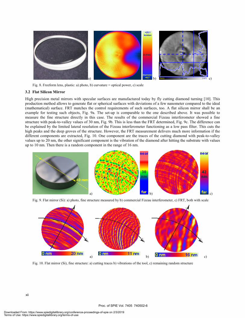
a) b) c)
Fig. 8. Freeform lens, plastic: a) photo, b) curvature = optical power, c) scale
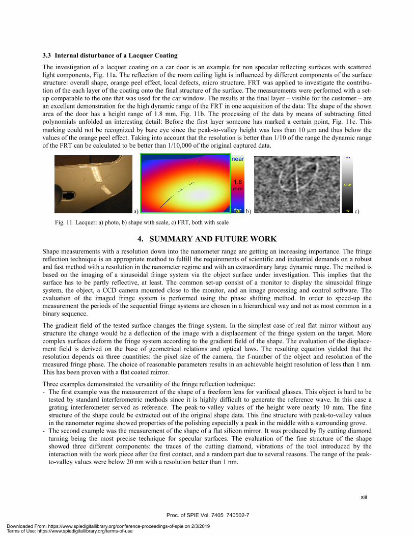
3.2 Flat Silicon Mirror
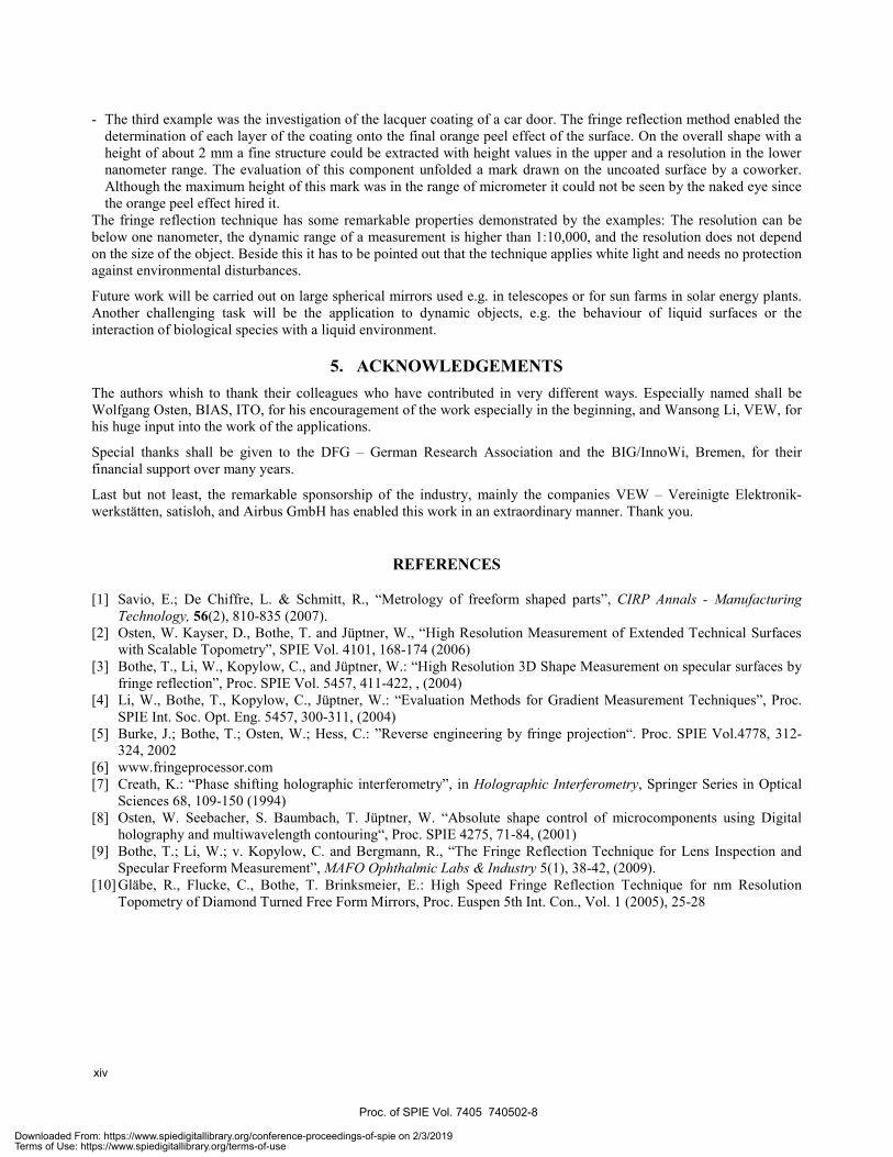
High precision metal mirrors with specular surfaces are manufactured today by fly cutting diamond turning [10]. This production method allows to generate flat or spherical surfaces with deviations of a few nanometer compared to the ideal (mathematical) surface. FRT matches the control requirements of such surfaces, too. A flat silicon mirror shall be an example for testing such objects, Fig. 9a. The set-up is comparable to the one described above. It was possible to measure the fine structure directly in this case. The results of the commercial Fizeau interferometer showed a fine structure with peak-to-valley values of 30 nm, Fig. 9b. This is less than the FRT determined, Fig. 9c. The difference can be explained by the limited lateral resolution of the Fizeau interferometer functioning as a low pass filter. This cuts the high peaks and the deep groves of the structure. However, the FRT measurement delivers much more information if the different components are extracted, Fig. 10. One component are the traces of the cutting diamond with peak-to-valley values up to 20 nm, the other significant component is the vibration of the diamond after hitting the substrate with values up to 10 nm. Then there is a random component in the range of 16 nm.
a) b) c)
Fig. 9. Flat mirror (Si): a) photo, fine structure measured by b) commercial Fizeau interferometer, c) FRT, both with scale
a) b) c)
Fig. 10. Flat mirror (Si), fine structure: a) cutting traces b) vibrations of the tool, c) remaining random structure
(nah)(fern) 780 nm
(konvex)+8.7
+25.1konkav
D (1/m)
Proc. of SPIE Vol. 7405 740502-6
xii
Downloaded From: https://www.spiedigitallibrary.org/conference-proceedings-of-spie on 2/3/2019Terms of Use: https://www.spiedigitallibrary.org/terms-of-use
3.3 Internal disturbance of a Lacquer Coating
The investigation of a lacquer coating on a car door is an example for non specular reflecting surfaces with scattered light components, Fig. 11a. The reflection of the room ceiling light is influenced by different components of the surface structure: overall shape, orange peel effect, local defects, micro structure. FRT was applied to investigate the contribu-tion of the each layer of the coating onto the final structure of the surface. The measurements were performed with a set-up comparable to the one that was used for the car window. The results at the final layer – visible for the customer – are an excellent demonstration for the high dynamic range of the FRT in one acquisition of the data: The shape of the shown area of the door has a height range of 1.8 mm, Fig. 11b. The processing of the data by means of subtracting fitted polynomials unfolded an interesting detail: Before the first layer someone has marked a certain point, Fig. 11c. This marking could not be recognized by bare eye since the peak-to-valley height was less than 10 μm and thus below the values of the orange peel effect. Taking into account that the resolution is better than 1/10 of the range the dynamic range of the FRT can be calculated to be better than 1/10,000 of the original captured data.
a) b) c)
Fig. 11. Lacquer: a) photo, b) shape with scale, c) FRT, both with scale
4. SUMMARY AND FUTURE WORK Shape measurements with a resolution down into the nanometer range are getting an increasing importance. The fringe reflection technique is an appropriate method to fulfill the requirements of scientific and industrial demands on a robust and fast method with a resolution in the nanometer regime and with an extraordinary large dynamic range. The method is based on the imaging of a sinusoidal fringe system via the object surface under investigation. This implies that the surface has to be partly reflective, at least. The common set-up consist of a monitor to display the sinusoidal fringe system, the object, a CCD camera mounted close to the monitor, and an image processing and control software. The evaluation of the imaged fringe system is performed using the phase shifting method. In order to speed-up the measurement the periods of the sequential fringe systems are chosen in a hierarchical way and not as most common in a binary sequence.
The gradient field of the tested surface changes the fringe system. In the simplest case of real flat mirror without any structure the change would be a deflection of the image with a displacement of the fringe system on the target. More complex surfaces deform the fringe system according to the gradient field of the shape. The evaluation of the displace-ment field is derived on the base of geometrical relations and optical laws. The resulting equation yielded that the resolution depends on three quantities: the pixel size of the camera, the f-number of the object and resolution of the measured fringe phase. The choice of reasonable parameters results in an achievable height resolution of less than 1 nm. This has been proven with a flat coated mirror.
Three examples demonstrated the versatility of the fringe reflection technique: - The first example was the measurement of the shape of a freeform lens for varifocal glasses. This object is hard to be
tested by standard interferometric methods since it is highly difficult to generate the reference wave. In this case a grating interferometer served as reference. The peak-to-valley values of the height were nearly 10 mm. The fine structure of the shape could be extracted out of the original shape data. This fine structure with peak-to-valley values in the nanometer regime showed properties of the polishing especially a peak in the middle with a surrounding grove.
- The second example was the measurement of the shape of a flat silicon mirror. It was produced by fly cutting diamond turning being the most precise technique for specular surfaces. The evaluation of the fine structure of the shape showed three different components: the traces of the cutting diamond, vibrations of the tool introduced by the interaction with the work piece after the first contact, and a random part due to several reasons. The range of the peak-to-valley values were below 20 nm with a resolution better than 1 nm.
near
1.8mm
far
Proc. of SPIE Vol. 7405 740502-7
xiii
Downloaded From: https://www.spiedigitallibrary.org/conference-proceedings-of-spie on 2/3/2019Terms of Use: https://www.spiedigitallibrary.org/terms-of-use
- The third example was the investigation of the lacquer coating of a car door. The fringe reflection method enabled the determination of each layer of the coating onto the final orange peel effect of the surface. On the overall shape with a height of about 2 mm a fine structure could be extracted with height values in the upper and a resolution in the lower nanometer range. The evaluation of this component unfolded a mark drawn on the uncoated surface by a coworker. Although the maximum height of this mark was in the range of micrometer it could not be seen by the naked eye since the orange peel effect hired it.
The fringe reflection technique has some remarkable properties demonstrated by the examples: The resolution can be below one nanometer, the dynamic range of a measurement is higher than 1:10,000, and the resolution does not depend on the size of the object. Beside this it has to be pointed out that the technique applies white light and needs no protection against environmental disturbances.
Future work will be carried out on large spherical mirrors used e.g. in telescopes or for sun farms in solar energy plants. Another challenging task will be the application to dynamic objects, e.g. the behaviour of liquid surfaces or the interaction of biological species with a liquid environment.
5. ACKNOWLEDGEMENTS The authors whish to thank their colleagues who have contributed in very different ways. Especially named shall be Wolfgang Osten, BIAS, ITO, for his encouragement of the work especially in the beginning, and Wansong Li, VEW, for his huge input into the work of the applications.
Special thanks shall be given to the DFG – German Research Association and the BIG/InnoWi, Bremen, for their financial support over many years.
Last but not least, the remarkable sponsorship of the industry, mainly the companies VEW – Vereinigte Elektronik-werkstätten, satisloh, and Airbus GmbH has enabled this work in an extraordinary manner. Thank you.
REFERENCES
[1] Savio, E.; De Chiffre, L. & Schmitt, R., “Metrology of freeform shaped parts”, CIRP Annals - Manufacturing Technology, 56(2), 810-835 (2007).
[2] Osten, W. Kayser, D., Bothe, T. and Jüptner, W., “High Resolution Measurement of Extended Technical Surfaces with Scalable Topometry”, SPIE Vol. 4101, 168-174 (2006)
[3] Bothe, T., Li, W., Kopylow, C., and Jüptner, W.: “High Resolution 3D Shape Measurement on specular surfaces by fringe reflection”, Proc. SPIE Vol. 5457, 411-422, , (2004)
[4] Li, W., Bothe, T., Kopylow, C., Jüptner, W.: “Evaluation Methods for Gradient Measurement Techniques”, Proc. SPIE Int. Soc. Opt. Eng. 5457, 300-311, (2004)
[5] Burke, J.; Bothe, T.; Osten, W.; Hess, C.: ”Reverse engineering by fringe projection“. Proc. SPIE Vol.4778, 312-324, 2002
[6] www.fringeprocessor.com [7] Creath, K.: “Phase shifting holographic interferometry”, in Holographic Interferometry, Springer Series in Optical
Sciences 68, 109-150 (1994) [8] Osten, W. Seebacher, S. Baumbach, T. Jüptner, W. “Absolute shape control of microcomponents using Digital
holography and multiwavelength contouring“, Proc. SPIE 4275, 71-84, (2001) [9] Bothe, T.; Li, W.; v. Kopylow, C. and Bergmann, R., “The Fringe Reflection Technique for Lens Inspection and
Specular Freeform Measurement”, MAFO Ophthalmic Labs & Industry 5(1), 38-42, (2009). [10] Gläbe, R., Flucke, C., Bothe, T. Brinksmeier, E.: High Speed Fringe Reflection Technique for nm Resolution
Topometry of Diamond Turned Free Form Mirrors, Proc. Euspen 5th Int. Con., Vol. 1 (2005), 25-28
Proc. of SPIE Vol. 7405 740502-8
xiv
Downloaded From: https://www.spiedigitallibrary.org/conference-proceedings-of-spie on 2/3/2019Terms of Use: https://www.spiedigitallibrary.org/terms-of-use