Embed Size (px)
Citation preview
PROCEEDINGS OF SPIE
SPIEDigitalLibrary.org/conference-proceedings-of-spie
Front Matter: Volume 6464
, "Front Matter: Volume 6464," Proc. SPIE 6464, MEMS/MOEMSComponents and Their Applications IV, 646401 (8 March 2007); doi:10.1117/12.730343
Event: MOEMS-MEMS 2007 Micro and Nanofabrication, 2007, San Jose,California, United States
Downloaded From: https://www.spiedigitallibrary.org/conference-proceedings-of-spie on 28 Feb 2020 Terms of Use: https://www.spiedigitallibrary.org/terms-of-use
The International Society
for Optical Engineering
Proceedings of SPIE—The International Society for Optical Engineering, 9780819465771, v. 6464
SPIE is an international technical society dedicated to advancing engineering and scientific applications of optical, photonic, imaging, electronic, and optoelectronic technologies.
MEMS/MOEMS Components and Their Applications IV
Srinivas A. Tadigadapa Reza Ghodssi Albert K. Henning Chairs/Editors 22–23 January 2007 San Jose, California, USA Sponsored and Published by SPIE—The International Society for Optical Engineering
Volume 6464
��������������� ������������ �������������� ������������������������������������� �� �� ��������� ����������������� ������� � ����� ������ � �����
PROCEEDINGS OF SPIE
Downloaded From: https://www.spiedigitallibrary.org/conference-proceedings-of-spie on 28 Feb 2020Terms of Use: https://www.spiedigitallibrary.org/terms-of-use
The papers included in this volume were part of the technical conference cited on the cover and title page. Papers were selected and subject to review by the editors and conference program committee. Some conference presentations may not be available for publication. The papers published in these proceedings reflect the work and thoughts of the authors and are published herein as submitted. The publisher is not responsible for the validity of the information or for any outcomes resulting from reliance thereon. Please use the following format to cite material from this book: Author(s), "Title of Paper," in MEMS/MOEMS Components and Their Applications IV, edited by Srinivas A. Tadigadapa, Reza Ghodssi, Albert K. Henning, Proceedings of SPIE Vol. 6464 (SPIE, Bellingham, WA, 2007) Article CID Number. ISSN 0277-786X ISBN 9780819465771 Published by SPIE—The International Society for Optical Engineering P.O. Box 10, Bellingham, Washington 98227-0010 USA Telephone 1 360/676-3290 (Pacific Time)· Fax 1 360/647-1445 http://www.spie.org Copyright © 2007, The Society of Photo-Optical Instrumentation Engineers Copying of material in this book for internal or personal use, or for the internal or personal use of specific clients, beyond the fair use provisions granted by the U.S. Copyright Law is authorized by SPIE subject to payment of copying fees. The Transactional Reporting Service base fee for this volume is $18.00 per article (or portion thereof), which should be paid directly to the Copyright Clearance Center (CCC), 222 Rosewood Drive, Danvers, MA 01923. Payment may also be made electronically through CCC Online at http://www.copyright.com. Other copying for republication, resale, advertising or promotion, or any form of systematic or multiple reproduction of any material in this book is prohibited except with permission in writing from the publisher. The CCC fee code is 0277-786X/07/$18.00. Printed in the United States of America.
Downloaded From: https://www.spiedigitallibrary.org/conference-proceedings-of-spie on 28 Feb 2020Terms of Use: https://www.spiedigitallibrary.org/terms-of-use
Contents
vii Conference Committee ix MEMS for medical technology applications (Plenary Paper) [6465-40] T. Frisk, N. Roxhed, G. Stemme, Royal Institute of Technology (Sweden) MICRO/NANOTECHNOLOGY AND BIOLOGY 646403 Drosophila as an unconventional substrate for microfabrication (Invited Paper) [6464-02] A. J. Shum, B. A. Parviz, Univ. of Washington (USA) 646404 Integrated biophotonic hybridization sensor based on chitosan-mediated assembly
[6464-03] V. Badilita, M. Powers, S. Koev, Univ. of Maryland, College Park (USA); H. Yi, Univ. of
Maryland, College Park (USA) and Tufts Univ. (USA); G. Payne, R. Ghodssi, Univ. of Maryland, College Park (USA)
646405 Self assembled monolayer and protein adsorption studies on micromachined quartz
crystal balances [6464-04] P. Kao, A. Goyal, J. Mathews, D. Allara, S. Tadigadapa, The Pennsylvania State Univ. (USA) NANOTECHNOLOGY 646406 Nanomechanical cantilever arrays for low-power and low-voltage embedded nonvolatile
memory applications (Invited Paper) [6464-05] C. G. Smith, Cavendish Lab. (United Kingdom); R. van Kampen, J. Popp, Cavendish
Kinetics B.V. (Netherlands); D. Lacy, D. Pinchetti, M. Renault, V. Joshi, M. A. Beunder, Cavendish Kinetics Inc. (USA)
646407 Nanoelectromechanical systems as single electron switches and field emitters (Invited
Paper) [6464-06] H. S. Kim, H. Qin, R. H. Blick, Univ. of Wisconsin-Madison (USA)
Pagination: Proceedings of SPIE follow an e-First publication model, with papers published first online and then in print and on CD-ROM. Papers are published as they are submitted and meet publication criteria. A unique, consistent, permanent citation identifier (CID) number is assigned to each article at the time of the first publication. Utilization of CIDs allows articles to be fully citable as soon they are published online, and connects the same identifier to all online, print, and electronic versions of the publication. SPIE uses a six-digit CID article numbering system in which: • The first four digits correspond to the SPIE volume number. • The last two digits indicate publication order within the volume using a Base 36 numbering system employing both numerals and letters. These two-number sets start with 00, 01, 02, 03, 04, 05, 06, 07, 08, 09, 0A, 0B … 0Z, followed by 10-1Z, 20-2Z, etc. The CID number appears on each page of the manuscript. The complete citation is used on the first page, and an abbreviated version on subsequent pages.
iii
Downloaded From: https://www.spiedigitallibrary.org/conference-proceedings-of-spie on 28 Feb 2020Terms of Use: https://www.spiedigitallibrary.org/terms-of-use
646408 Coated tips for scanning thermal microscopy [6464-07] N. Duarte, P. Eklund, S. Tadigadapa, The Pennsylvania State Univ. (USA) 646409 Electrical properties of back-gated n-layer graphene films [6464-08] P. Joshi, A. Gupta, P. C. Eklund, S. Tadigadapa, The Pennsylvania State Univ. (USA) 64640A Micromachined silicon grids for direct TEM and Raman characterization of CVD grown
carbon nanotubes [6464-09] Y. Choi, A. Ural, Univ. of Florida (USA) NANOMECHANICS AND RESONATORS 64640B Mechanical properties of ZnO nanowires (Invited Paper) [6464-10] M. A. Haque, A. V. Desai, The Pennsylvania State Univ. (USA) 64640C MEMS-based testing stage to study electrical and mechanical properties of
nanocrystalline metal films [6464-11] J. H. Han, J. Rajagopalan, M. T. A. Saif, Univ. of Illinois at Urbana-Champaign (USA) 64640D All-optical micromechanical chemical sensors (Invited Paper) [6464-12] T. H. Stievater, W. S. Rabinovich, M. S. Ferraro, J. B. Boos, N. A. Papanicolaou,
J. L. Stepnowski, R. A. McGill, Naval Research Lab. (USA) 64640E Integrated nanomechanical motion detection by means of optical evanescent wave
coupling [6464-13] I. De Vlaminck, Imec (Belgium); J. Roels, D. Taillaert, D. Van Thourhout, Ghent Univ.-IMEC
(Belgium); L. Lagae, Imec (Belgium); R. Baets, Ghent Univ.-IMEC (Belgium); G. Borghs, Imec (Belgium)
MICROELECTROMECHANICAL SYSTEMS I 64640H Development of amorphous SiC for MEMS-based microbridges [6464-16] J. B. Summers, Case Western Reserve Univ. (USA); M. Scardelletti, NASA Glenn Research Ctr.
(USA); R. Parro, C. A. Zorman, Case Western Reserve Univ. (USA) 64640I Fabrication of comb-drive micro-actuators based on UV lithography of SU-8 and
electroless plating technique [6464-17] W. Dai, W. Wang, Louisiana State Univ. (USA) 64640J On-chip integration of a microfluidic valve and pump for sample acquisition and
movement [6464-18] S. S. Sridharamurthy, Univ. of Wisconsin-Madison (USA); A. K. Agarwal, Northwestern Univ.
(USA); L. Dong, D. Cheng, H. Jiang, Univ. of Wisconsin-Madison (USA) MICROELECTROMECHANICAL SYSTEMS II 64640L IR detectors with adaptive responsivity and wavelength (Invited Paper) [6464-21] W.-B. Song, J. J. Talghader, Univ. of Minnesota (USA)
iv
Downloaded From: https://www.spiedigitallibrary.org/conference-proceedings-of-spie on 28 Feb 2020Terms of Use: https://www.spiedigitallibrary.org/terms-of-use
64640M LVD micromirror for rapid reference scanning in optical coherence tomography [6464-22] X. Feng, A. Jain, S. Pal, L. Xiao, T. Nishida, H. Xie, Univ. of Florida (USA) 64640N Process development, design, and characterization of high-finesse micromachined optical
Fabry-Perot microcavities [6464-23] M. W. Pruessner, T. H. Stievater, W. S. Rabinovich, Naval Research Lab. (USA) 64640O Silicon/porous silicon composite membrane for high-sensitivity pressure sensor [6464-24] L. Sujatha, E. Bhattacharya, Indian Institute of Technology Madras (India) 64640Q Stereolithography as a meso-structure for input force reduction to a capacitive force MEMS
sensor [6464-26] H. K. Chu, J. K. Mills, W. L. Cleghorn, Univ. of Toronto (Canada)
Author Index
v
Downloaded From: https://www.spiedigitallibrary.org/conference-proceedings-of-spie on 28 Feb 2020Terms of Use: https://www.spiedigitallibrary.org/terms-of-use

Downloaded From: https://www.spiedigitallibrary.org/conference-proceedings-of-spie on 28 Feb 2020Terms of Use: https://www.spiedigitallibrary.org/terms-of-use
Conference Committee
Symposium Chairs
Rajeshuni Ramesham, Jet Propulsion Laboratory (USA)
Symposium Cochair
Albert K. Henning, Aquarian Microsystems (USA)
Conference Chairs
Srinivas A. Tadigadapa, The Pennsylvania State University (USA) Reza Ghodssi, University of Maryland/College Park (USA) Albert K. Henning, Aquarian Microsystems (USA)
Program Committee
Hongrui Jiang, University of Wisconsin/Madison (USA) Rudra Pratap, Indian Institute of Science (India) Marcel W. Pruessner, Naval Research Laboratory (USA) Mohammed T. Saif, University of Illinois at Urbana-Champaign (USA) Wanjun Wang, Louisiana State University (USA) Huikai Xie, University of Florida (USA) Christian A. Zorman, Case Western Reserve University (USA)
Session Chairs
Micro/Nanotechnology and Biology Reza Ghodssi, University of Maryland/College Park (USA)
Nanotechnology Albert K. Henning, Aquarian Microsystems (USA)
Nanomechanics and Resonators Christian A. Zorman, Case Western Reserve University (USA)
Microelectromechanical Systems I Huikai Xie, University of Florida (USA)
Microelectromechanical Systems II Rudra Pratap, Indian Institute of Science (India)
vii
Downloaded From: https://www.spiedigitallibrary.org/conference-proceedings-of-spie on 28 Feb 2020Terms of Use: https://www.spiedigitallibrary.org/terms-of-use

Downloaded From: https://www.spiedigitallibrary.org/conference-proceedings-of-spie on 28 Feb 2020Terms of Use: https://www.spiedigitallibrary.org/terms-of-use
MEMS for Medical Technology Applications Thomas Frisk, Niclas Roxhed, Göran Stemme
Microsystem Technology Lab, School of Electrical Engineering Royal Institute of Technology (KTH), SE-100 44, Stockholm, Sweden
ABSTRACT
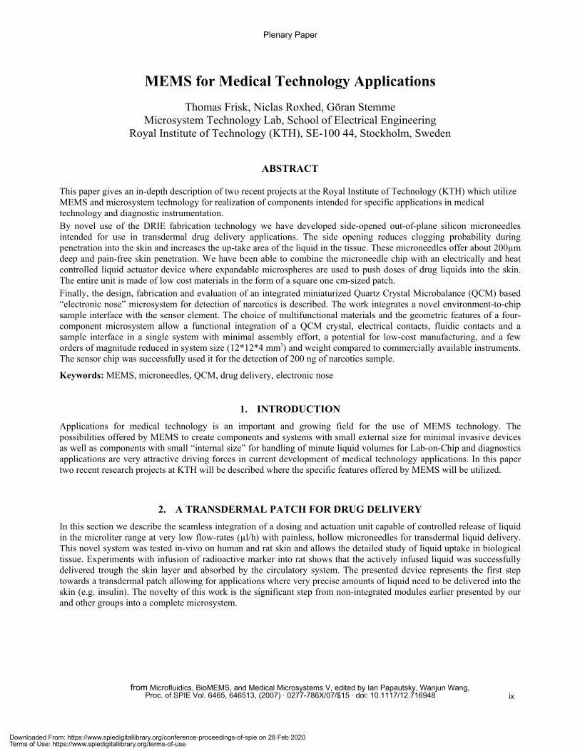
This paper gives an in-depth description of two recent projects at the Royal Institute of Technology (KTH) which utilize MEMS and microsystem technology for realization of components intended for specific applications in medical technology and diagnostic instrumentation. By novel use of the DRIE fabrication technology we have developed side-opened out-of-plane silicon microneedles intended for use in transdermal drug delivery applications. The side opening reduces clogging probability during penetration into the skin and increases the up-take area of the liquid in the tissue. These microneedles offer about 200µm deep and pain-free skin penetration. We have been able to combine the microneedle chip with an electrically and heat controlled liquid actuator device where expandable microspheres are used to push doses of drug liquids into the skin. The entire unit is made of low cost materials in the form of a square one cm-sized patch. Finally, the design, fabrication and evaluation of an integrated miniaturized Quartz Crystal Microbalance (QCM) based “electronic nose” microsystem for detection of narcotics is described. The work integrates a novel environment-to-chip sample interface with the sensor element. The choice of multifunctional materials and the geometric features of a four-component microsystem allow a functional integration of a QCM crystal, electrical contacts, fluidic contacts and a sample interface in a single system with minimal assembly effort, a potential for low-cost manufacturing, and a few orders of magnitude reduced in system size (12*12*4 mm3) and weight compared to commercially available instruments. The sensor chip was successfully used it for the detection of 200 ng of narcotics sample.
Keywords: MEMS, microneedles, QCM, drug delivery, electronic nose
1. INTRODUCTIONApplications for medical technology is an important and growing field for the use of MEMS technology. The possibilities offered by MEMS to create components and systems with small external size for minimal invasive devices as well as components with small “internal size” for handling of minute liquid volumes for Lab-on-Chip and diagnostics applications are very attractive driving forces in current development of medical technology applications. In this paper two recent research projects at KTH will be described where the specific features offered by MEMS will be utilized.
2. A TRANSDERMAL PATCH FOR DRUG DELIVERY In this section we describe the seamless integration of a dosing and actuation unit capable of controlled release of liquid in the microliter range at very low flow-rates (µl/h) with painless, hollow microneedles for transdermal liquid delivery. This novel system was tested in-vivo on human and rat skin and allows the detailed study of liquid uptake in biological tissue. Experiments with infusion of radioactive marker into rat shows that the actively infused liquid was successfully delivered trough the skin layer and absorbed by the circulatory system. The presented device represents the first step towards a transdermal patch allowing for applications where very precise amounts of liquid need to be delivered into the skin (e.g. insulin). The novelty of this work is the significant step from non-integrated modules earlier presented by our and other groups into a complete microsystem.
Plenary Paper
from Microfluidics, BioMEMS, and Medical Microsystems V, edited by Ian Papautsky, Wanjun Wang,Proc. of SPIE Vol. 6465, 646513, (2007) · 0277-786X/07/$15 · doi: 10.1117/12.716948 ix
Downloaded From: https://www.spiedigitallibrary.org/conference-proceedings-of-spie on 28 Feb 2020Terms of Use: https://www.spiedigitallibrary.org/terms-of-use
11111 croneedle array
Reservoir
composite
IUnexpanded
PCB
'liii ReIead ]iquid
2.1 Microsystem based drug delivery
Drug delivery using minimally invasive microneedles provide a promising technology for painless administration of macromolecular drugs such as insulin or vaccines [1], [2]. Over the recent years a variety of microneedle designs, both solid e.g. [3], [4] and hollow e.g. [5]-[9], have been presented. In addition, during the last 1-2 year period, focus has shifted to in-vivo studies [10]-[13] and associated reliability issues such as fracture failure, skin penetration and liquid uptake by the skin [8], [9], [14], [15]. However, there is still very little work on integration of microneedles into complete drug delivery systems such as a transdermal patch. Stoeber and Liepmann [16] have joined hollow out-of-plane microneedles with a flexible PDMS liquid container for manual thumb actuation. On-chip microfluidic pumping for an in-plane microneedle has been presented by Zahn et al. [17]. However, integration of actively controlled pumping of drugs with out-of plane microneedles has not been shown yet. Except for difficulties to integrate pumping units with out-of-plane structures, we have also seen that the amount of liquid that can be injected into the shallow skin regions is highly limited [9]. Hence, a microneedle pumping unit needs to be capable of delivering liquid with low flow-rates in the order of µl/h to avoid liquid saturation of the skin at the needle insertion point.
2.2 Principle design
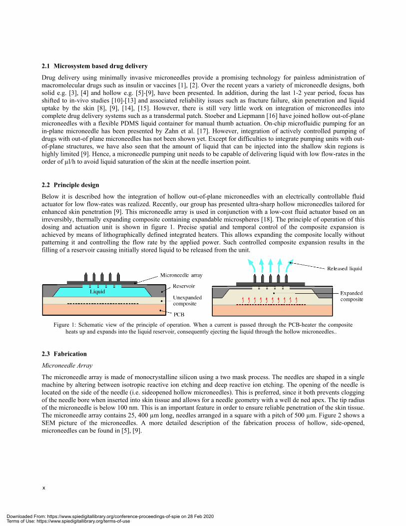
Below it is described how the integration of hollow out-of-plane microneedles with an electrically controllable fluid actuator for low flow-rates was realized. Recently, our group has presented ultra-sharp hollow microneedles tailored for enhanced skin penetration [9]. This microneedle array is used in conjunction with a low-cost fluid actuator based on an irreversibly, thermally expanding composite containing expandable microspheres [18]. The principle of operation of this dosing and actuation unit is shown in figure 1. Precise spatial and temporal control of the composite expansion is achieved by means of lithographically defined integrated heaters. This allows expanding the composite locally without patterning it and controlling the flow rate by the applied power. Such controlled composite expansion results in the filling of a reservoir causing initially stored liquid to be released from the unit.
Figure 1: Schematic view of the principle of operation. When a current is passed through the PCB-heater the composite heats up and expands into the liquid reservoir, consequently ejecting the liquid through the hollow microneedles..
2.3 Fabrication
Microneedle Array
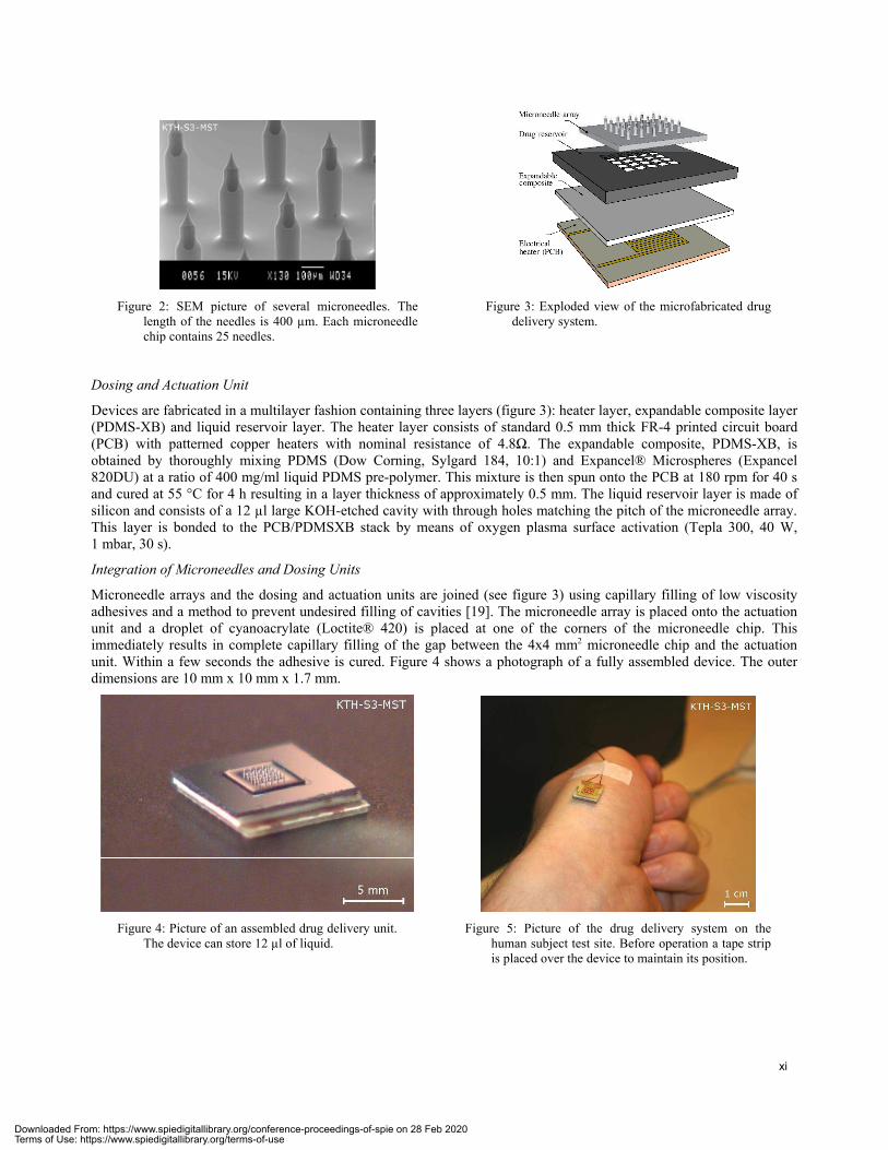
The microneedle array is made of monocrystalline silicon using a two mask process. The needles are shaped in a single machine by altering between isotropic reactive ion etching and deep reactive ion etching. The opening of the needle is located on the side of the needle (i.e. sideopened hollow microneedles). This is preferred, since it both prevents clogging of the needle bore when inserted into skin tissue and allows for a needle geometry with a well de ned apex. The tip radius of the microneedle is below 100 nm. This is an important feature in order to ensure reliable penetration of the skin tissue. The microneedle array contains 25, 400 µm long, needles arranged in a square with a pitch of 500 µm. Figure 2 shows a SEM picture of the microneedles. A more detailed description of the fabrication process of hollow, side-opened, microneedles can be found in [5], [9].
x
Downloaded From: https://www.spiedigitallibrary.org/conference-proceedings-of-spie on 28 Feb 2020Terms of Use: https://www.spiedigitallibrary.org/terms-of-use
Pr'4, 1
Microrree1]e Y
Dreg reservoir
hester (PCB)
Figure 2: SEM picture of several microneedles. The length of the needles is 400 µm. Each microneedle chip contains 25 needles.
Figure 3: Exploded view of the microfabricated drug delivery system.
Dosing and Actuation Unit
Devices are fabricated in a multilayer fashion containing three layers (figure 3): heater layer, expandable composite layer (PDMS-XB) and liquid reservoir layer. The heater layer consists of standard 0.5 mm thick FR-4 printed circuit board (PCB) with patterned copper heaters with nominal resistance of 4.8 . The expandable composite, PDMS-XB, is obtained by thoroughly mixing PDMS (Dow Corning, Sylgard 184, 10:1) and Expancel® Microspheres (Expancel 820DU) at a ratio of 400 mg/ml liquid PDMS pre-polymer. This mixture is then spun onto the PCB at 180 rpm for 40 s and cured at 55 °C for 4 h resulting in a layer thickness of approximately 0.5 mm. The liquid reservoir layer is made of silicon and consists of a 12 µl large KOH-etched cavity with through holes matching the pitch of the microneedle array. This layer is bonded to the PCB/PDMSXB stack by means of oxygen plasma surface activation (Tepla 300, 40 W, 1 mbar, 30 s).
Integration of Microneedles and Dosing Units
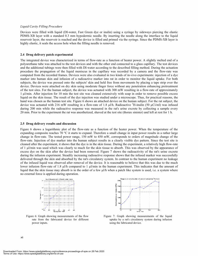
Microneedle arrays and the dosing and actuation units are joined (see figure 3) using capillary filling of low viscosity adhesives and a method to prevent undesired filling of cavities [19]. The microneedle array is placed onto the actuation unit and a droplet of cyanoacrylate (Loctite® 420) is placed at one of the corners of the microneedle chip. This immediately results in complete capillary filling of the gap between the 4x4 mm2 microneedle chip and the actuation unit. Within a few seconds the adhesive is cured. Figure 4 shows a photograph of a fully assembled device. The outer dimensions are 10 mm x 10 mm x 1.7 mm.
Figure 4: Picture of an assembled drug delivery unit. The device can store 12 µl of liquid.
Figure 5: Picture of the drug delivery system on the human subject test site. Before operation a tape strip is placed over the device to maintain its position.
xi
Downloaded From: https://www.spiedigitallibrary.org/conference-proceedings-of-spie on 28 Feb 2020Terms of Use: https://www.spiedigitallibrary.org/terms-of-use
Liquid Cavity Filling Procedure
Devices were filled with liquid (DI-water, Fast Green dye or inulin) using a syringe by sideways piercing the elastic PDMS-XB layer with a standard 0.3 mm hypodermic needle. By inserting the needle along the interface to the liquid reservoir layer, the reservoir is reached and the device is filled and primed via the syringe. Since the PDMS-XB layer is highly elastic, it seals the access hole when the filling needle is removed.
2.4 Drug delivery patch experimental
The integrated device was characterized in terms of flow-rate as a function of heater power. A slightly melted end of a polyurethane tube was attached to the test devices and with the other end connected to a glass capillary. The test devices and the additional tubings were then filled with DI-water according to the described filling method. During the actuation procedure the propagation of the liquid meniscus in the capillary was recorded by a camera and the flow-rate was computed from the recorded frames. Devices were also evaluated in two kinds of in-vivo experiments: injection of a dye marker into human skin and infusion of a radioactive marker into rat in order to monitor the liquid uptake. For both subjects, the device was pressed onto the subjects' skin and held free from movements by placing a tape strip over the device. Devices were attached on dry skin using moderate finger force without any penetration enhancing pretreatment of the test sites. For the human subject, the device was actuated with 300 mW resulting in a flow-rate of approximately 1 µl/min. After injection for 10 min the test site was cleaned extensively with soap in order to remove possible excess liquid on the skin tissue. The result of the dye injection was studied under a microscope. Thus, for practical reasons, the hand was chosen as the human test site. Figure 6 shows an attached device on the human subject. For the rat subject, the device was actuated with 216 mW resulting in a flow-rate of 1.8 µl/h. Radioactive 3H-inulin (50 µCi/ml) was infused during 200 min while the radioactive response was measured in the rat's urine excrete by collecting a sample every 20 min. Prior to the experiment the rat was anesthetized, shaved at the test site (thorax sinister) and left at rest for 1 h.
2.5 Drug delivery results and discussion
Figure 6 shows a logarithmic plot of the flow-rate as a function of the heater power. When the temperature of the expanding composite reaches 70 °C it starts to expand. Therefore a small change in input power results in a rather large change in flow-rate. The tested power range, 150 mW to 450 mW, corresponds to orders of magnitude change of the flow-rate. Injection of dye marker into the human subject results in a clearly visible dye pattern. Since the test site is cleaned after the experiment, it shows that the dye is in the skin tissue. During the experiment, a relatively high flow-rate of 1 µl/min was used which was clearly to much for the skin tissue to absorb. This was observed by the appearance of excess dye on the skin after the device had been removed. Figure 7 shows the radioactivity of the rat's urine excrete during the infusion experiment. Steadily increasing radioactive response shows that the infused marker was successfully delivered through the skin and absorbed by the rat's circulatory system. In contrast to the human experiment no leakage of the infused liquid was observed after removal of the device. It is reasonable to believe that this was due to the much lower infusion flow-rate of 1.8 µl/h compared to 1 µl/min in the human experiment. This indicates that the amount of liquid that the skin tissue may absorb is in the order of a few µl/h when a patch like system is used, i.e. a system where no external force is applied during operation.
Figure 6: Graph showing measurements of the flow rate from the fabricated device for different power inputs.
Figure 7: Graph showing measurements of the liquid uptake by a rat's circulatory system during infusion using the fabricated device.
xii
Downloaded From: https://www.spiedigitallibrary.org/conference-proceedings-of-spie on 28 Feb 2020Terms of Use: https://www.spiedigitallibrary.org/terms-of-use
3. ELECTRONIC NOSE MICROSYSTEM The detection of drugs, explosives and biological substances has become an important part of security activities at airports, harbours and in public transportation. Also military and customs activities include detection and monitoring of chemicals. Environmental monitoring has become an issue of growing importance. In particular, fast, portable, yet sensitive electronic noses are needed.
We previously reported a measurement setup for narcotics detection [20] in which a micromachined interface for airborne sample-to-liquid adsorption is coupled to a downstream commercial QCM sensor bank.
But, in order to further reduce tubing lengths, number of robots, and number of pumps and in general, machine size, we wanted to substitute pumping with diffusion as the major transport mechanism, enabled through miniaturisation. Integration of sample adsorption site and QCM was the target of this study.
3.1 Design of electronic nose
The current work integrates a novel environment-to-chip sample interface with the QCM sensor element in a single microsystem.
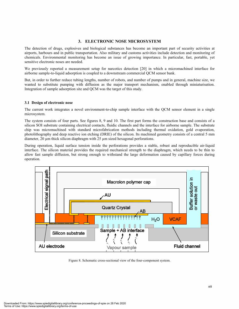
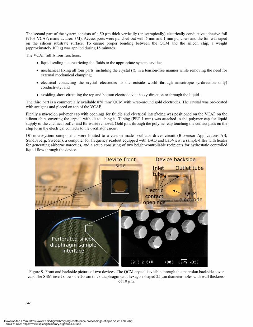
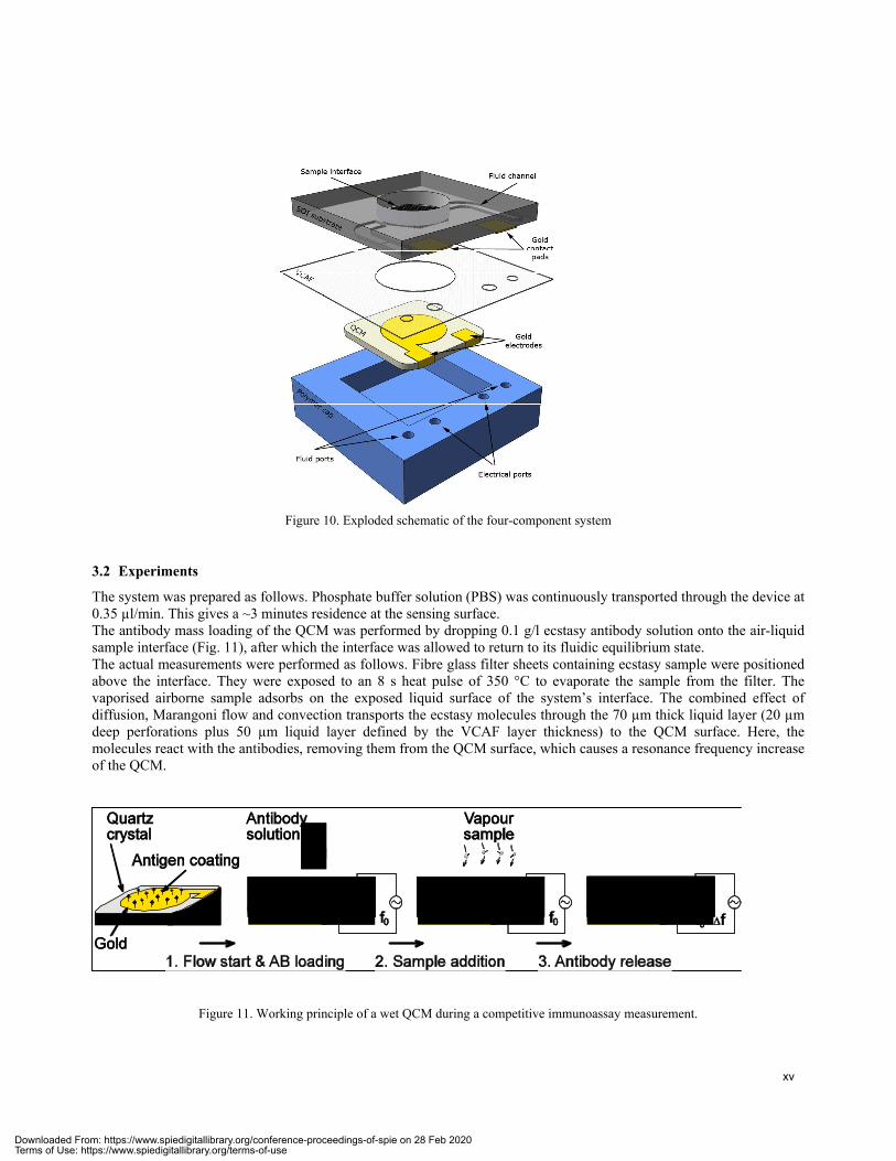
The system consists of four parts. See figures 8, 9 and 10. The first part forms the construction base and consists of a silicon SOI substrate containing electrical contacts, fluidic channels and the interface for airborne sample. The substrate chip was micromachined with standard microfabrication methods including thermal oxidation, gold evaporation, photolithography and deep reactive ion etching (DRIE) of the silicon. Its machined geometry consists of a central 5 mm diameter, 20 µm thick silicon diaphragm with 25 µm sized hexagonal perforations.
During operation, liquid surface tension inside the perforations provides a stable, robust and reproducible air-liquid interface. The silicon material provides the required mechanical strength to the diaphragm, which needs to be thin to allow fast sample diffusion, but strong enough to withstand the large deformation caused by capillary forces during operation.
Figure 8. Schematic cross-sectional view of the four-component system.
Sample + AB interface
Quartz Crystal
AU
H2O
ABEle
ctric
al s
igna
l pat
h
Buf
fer s
olut
ion
inor
was
te o
ut
VCAF
Macrolon polymer cap
Silicon substrate
Fluid channelAU electrode Vapour sample
xiii
Downloaded From: https://www.spiedigitallibrary.org/conference-proceedings-of-spie on 28 Feb 2020Terms of Use: https://www.spiedigitallibrary.org/terms-of-use
—I—___
LILIIIIJIIILL.
The second part of the system consists of a 50 µm thick vertically (anisotropically) electrically conductive adhesive foil (9703 VCAF; manufacturer: 3M). Access ports were punched-out with 5 mm and 1 mm punchers and the foil was taped on the silicon substrate surface. To ensure proper bonding between the QCM and the silicon chip, a weight (approximately 100 g) was applied during 15 minutes.
The VCAF fulfils four functions:
liquid sealing, i.e. restricting the fluids to the appropriate system cavities;
mechanical fixing all four parts, including the crystal (!), in a tension-free manner while removing the need for external mechanical clamping;
electrical contacting the crystal electrodes to the outside world through anisotropic (z-direction only) conductivity; and
avoiding short-circuiting the top and bottom electrode via the xy-direction or through the liquid.
The third part is a commercially available 8*8 mm2 QCM with wrap-around gold electrodes. The crystal was pre-coated with antigens and placed on top of the VCAF.
Finally a macrolon polymer cap with openings for fluidic and electrical interfacing was positioned on the VCAF on the silicon chip, covering the crystal without touching it. Tubing (PET 1 mm) was attached to the polymer cap for liquid supply of the chemical buffer and for waste removal. Gold pins through the polymer cap touching the contact pads on the chip form the electrical contacts to the oscillator circuit.
Off-microsystem components were limited to a custom made oscillator driver circuit (Biosensor Applications AB, Sundbyberg, Sweden), a computer for frequency readout equipped with DAQ and LabView, a sample-filter with heater for generating airborne narcotics, and a setup consisting of two height-controllable recipients for hydrostatic controlled liquid flow through the device.
Figure 9. Front and backside picture of two devices. The QCM crystal is visible through the macrolon backside cover cap. The SEM insert shows the 20 µm thick diaphragm with hexagon shaped 25 µm diameter holes with wall thickness
of 10 µm.
Inlettube
Outlet tube
QCMelectrode
Electriccontact
openings
Perforated silicon diaphragm sample
interface
Device front side
Device backside
xiv
Downloaded From: https://www.spiedigitallibrary.org/conference-proceedings-of-spie on 28 Feb 2020Terms of Use: https://www.spiedigitallibrary.org/terms-of-use
.::r; 44* 14_t_r
Figure 10. Exploded schematic of the four-component system
3.2 Experiments
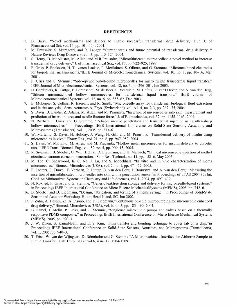
The system was prepared as follows. Phosphate buffer solution (PBS) was continuously transported through the device at 0.35 µl/min. This gives a ~3 minutes residence at the sensing surface. The antibody mass loading of the QCM was performed by dropping 0.1 g/l ecstasy antibody solution onto the air-liquid sample interface (Fig. 11), after which the interface was allowed to return to its fluidic equilibrium state. The actual measurements were performed as follows. Fibre glass filter sheets containing ecstasy sample were positioned above the interface. They were exposed to an 8 s heat pulse of 350 °C to evaporate the sample from the filter. The vaporised airborne sample adsorbs on the exposed liquid surface of the system’s interface. The combined effect of diffusion, Marangoni flow and convection transports the ecstasy molecules through the 70 µm thick liquid layer (20 µm deep perforations plus 50 µm liquid layer defined by the VCAF layer thickness) to the QCM surface. Here, the molecules react with the antibodies, removing them from the QCM surface, which causes a resonance frequency increase of the QCM.
Figure 11. Working principle of a wet QCM during a competitive immunoassay measurement.
Quartzcrystal
Antigen coating
Gold1. Flow start & AB loading 2. Sample addition 3. Antibody release
Vapoursample
f0 ff0
Antibodysolution
f0
xv
Downloaded From: https://www.spiedigitallibrary.org/conference-proceedings-of-spie on 28 Feb 2020Terms of Use: https://www.spiedigitallibrary.org/terms-of-use
3.3 Results
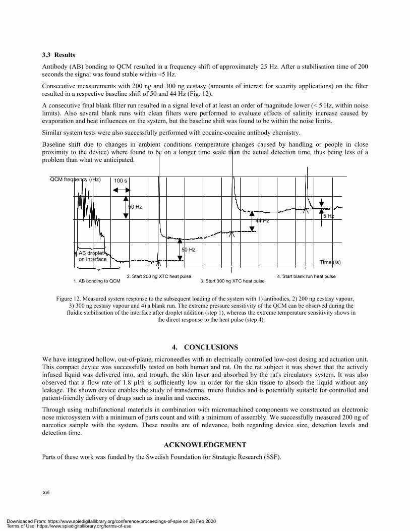
Antibody (AB) bonding to QCM resulted in a frequency shift of approximately 25 Hz. After a stabilisation time of 200 seconds the signal was found stable within ±5 Hz.
Consecutive measurements with 200 ng and 300 ng ecstasy (amounts of interest for security applications) on the filter resulted in a respective baseline shift of 50 and 44 Hz (Fig. 12).
A consecutive final blank filter run resulted in a signal level of at least an order of magnitude lower (< 5 Hz, within noise limits). Also several blank runs with clean filters were performed to evaluate effects of salinity increase caused by evaporation and heat influences on the system, but the baseline shift was found to be within the noise limits.
Similar system tests were also successfully performed with cocaine-cocaine antibody chemistry.
Baseline shift due to changes in ambient conditions (temperature changes caused by handling or people in close proximity to the device) where found to be on a longer time scale than the actual detection time, thus being less of a problem than what we anticipated.
Figure 12. Measured system response to the subsequent loading of the system with 1) antibodies, 2) 200 ng ecstasy vapour, 3) 300 ng ecstasy vapour and 4) a blank run. The extreme pressure sensitivity of the QCM can be observed during the
fluidic stabilisation of the interface after droplet addition (step 1), whereas the extreme temperature sensitivity shows in the direct response to the heat pulse (step 4).
4. CONCLUSIONS We have integrated hollow, out-of-plane, microneedles with an electrically controlled low-cost dosing and actuation unit. This compact device was successfully tested on both human and rat. On the rat subject it was shown that the actively infused liquid was delivered into, and trough, the skin layer and absorbed by the rat's circulatory system. It was also observed that a flow-rate of 1.8 µl/h is sufficiently low in order for the skin tissue to absorb the liquid without any leakage. The shown device enables the study of transdermal micro fluidics and is potentially suitable for controlled and patient-friendly delivery of drugs such as insulin and vaccines.
Through using multifunctional materials in combination with micromachined components we constructed an electronic nose microsystem with a minimum of parts count and with a minimum of assembly. We successfully measured 200 ng of narcotics sample with the system. These results are of relevance, both regarding device size, detection levels and detection time.
ACKNOWLEDGEMENTParts of these work was funded by the Swedish Foundation for Strategic Research (SSF).
AB droplet on interface
2. Start 200 ng XTC heat pulse3. Start 300 ng XTC heat pulse
4. Start blank run heat pulse1. AB bonding to QCM
QCM frequency (/Hz)
Time (/s)
100 s
50 Hz
44 Hz 5 Hz
50 Hz
xvi
Downloaded From: https://www.spiedigitallibrary.org/conference-proceedings-of-spie on 28 Feb 2020Terms of Use: https://www.spiedigitallibrary.org/terms-of-use
REFERENCES
1. B. Barry, “Novel mechanisms and devices to enable successful transdermal drug delivery,” Eur. J. of Pharmaceutical Sci, vol. 14, pp. 101–114, 2001.
2. M. Prausnitz, S. Mitragotri, and R. Langer, “Current status and future potential of transdermal drug delivery, “ Nature Reviews Drug Discovery, vol. 3, pp. 115–124, 2004.
3. S. Henry, D. McAllister, M. Allen, and M.R.Prausnitz, “Microfabricated microneedles: a novel method to increase transdermal drug delivery,” J. of Pharmaceutical Sci., vol. 87, pp. 922–925, 1998.
4. P. Griss, P. Enoksson, H. Tolvanen-Laakso, P. Merilainen, S. Ollmar, and G. Stemme, “Micromachined electrodes for biopotential measurements,”IEEE Journal of Microelectromechanical Systems, vol. 10, no. 1, pp. 10–16, Mar 2001.
5. P. Griss and G. Stemme, “Side-opened out-of-plane microneedles for micro fluidic transdermal liquid transfer,” IEEE Journal of Microelectromechanical Systems, vol. 12, no. 3, pp. 296–301, Jun 2003.
6. H. Gardeniers, R. Luttge, E. Berenschot, M. de Boer, S. Yeshurun, M. Hefetz, R. van't Oever, and A. van den Berg, “Silicon micromachined hollow microneedles for transdermal liquid transport,” IEEE Journal of Microelectromechanical Systems, vol. 12, no. 6, pp. 855–62, Dec 2003.
7. E. Mukerjee, S. Collins, R. Isseroff, and R. Smith, “Microneedle array for transdermal biological fluid extraction and in situ analysis,” Sens. Actuators A, Phys. (Switzerland), vol. A114, no. 2-3, pp. 267 –75, 2004.
8. S. Davis, B. Landis, Z. Adams, M. Allen, and M. Prausnitz, “Insertion of microneedles into skin: measurement and prediction of insertion force and needle fracture force,” J. of Biomechanics, vol. 37, pp. 1155–1163, 2004.
9. N. Roxhed, P. Griss, and G. Stemme, “Reliable in-vivo penetration and transdermal injection using ultra-sharp hollow microneedles,” in Proceedings IEEE International Conference on Solid-State Sensors, Actuators, and Microsystems (Transducers), vol. 1, 2005, pp. 213–6.
10. W. Martanto, S. Davis, H. Holiday, J. Wang, H. Gill, and M. Prausnitz, “Transdermal delivery of insulin using microneedles in vivo.” Pharm Res., vol. 21, no. 6, pp. 947–952, 2004.
11. S. Davis, W. Martanto, M. Allen, and M. Prausnitz, “Hollow metal microneedles for insulin delivery to diabetic rats,” IEEE Trans. Biomed. Eng., vol. 52, no. 5, pp. 909–15, 2005.
12. R. Sivamani, B. Stoeber, G. Wu, H. Zhai, D. Liepmann, and H. Maibach, “Clinical microneedle injection of methyl nicotinate: stratum corneum penetration,“ Skin Res. Technol., no. 11, pp. 152–6, May 2005.
13. M. Teo, C. Shearwood, K. C. Ng, J. Lu, and S. Moochhala, “In vitro and in vivo characterization of mems microneedles,” Biomed. Microdevices (USA), vol. 7, no. 1, pp. 47 – 52, 2005.
14. P. Loeters, R. Duwel, F. Verbaan, R. Luttge, D. van den Berg, J. Bouwstra, and A. van den Berg, “Measuring the insertion of microfabricated microneedles into skin with a penetration sensor,”in Proceedings of µTAS 2004 8th Int. Conf. on Miniaturized Systems in Chemistry and Life Sciences, vol. 1, 2004, pp. 497–499.
15. N. Roxhed, P. Griss, and G. Stemme, “Generic leakfree drug storage and delivery for microneedle-based systems,” in Proceedings IEEE International Conference on Micro Electro MechanicalSystems (MEMS), 2005, pp. 742–6.
16. B. Stoeber and D. Liepmann, “Design, fabrication, and testing of a mems syringe,” in Proceedings of Solid-State Sensor and Actuator Workshop, Hilton Head Island, SC, Jun 2002.
17. J. Zahn, A. Deshmukh, A. Pisano, and D. Liepmann,”Continuous on-chip micropumping for microneedle enhanced drug delivery,” Biomed. Microdevices (USA), vol. 6, no. 3, pp. 183 – 90, 2004.
18. B. Samel, J. Melin, P. Griss, and G. Stemme, “Singleuse micro uidic pumps and valves based on a thermally responsive PDMS composite,” in Proceedings IEEE International Conference on Micro Electro Mechanical Systems (MEMS), 2005, pp. 690–3.
19. J. W. Kwon, S. Kamal-Bahl, and E. S. Kim, “Film transfer and bonding technique to cover lab on a chip,”in Proceedings IEEE International Conference on Solid-State Sensors, Actuators, and Microsystems (Transducers), vol. 1, 2005, pp. 940–3.
20. T. Frisk, W. van der Wijngaart, D. Rönnholm and G. Stemme “A Micromachined Interface for Airborne Sample to Liquid Transfer”, Lab. Chip., 2006, vol 6, issue 12, 1504-1509.
xvii
Downloaded From: https://www.spiedigitallibrary.org/conference-proceedings-of-spie on 28 Feb 2020Terms of Use: https://www.spiedigitallibrary.org/terms-of-use

Downloaded From: https://www.spiedigitallibrary.org/conference-proceedings-of-spie on 28 Feb 2020Terms of Use: https://www.spiedigitallibrary.org/terms-of-use