Embed Size (px)
Citation preview

Problems on Force Exerted by a Magnetic Fields from Ch 26 T&M
Problem 26.27 A current-carrying wire is bent into a semicircular loop of radius R that lies in the xy plane. There is a uniform magnetic field B = Bk perpendicular to the plane of the loop. Verify that the force acting on the loop is zero.
Picture the Problem With the current in the direction indicated and the magnetic field in the z direction, pointing out of the plane of the page, the force is in the radial direction and we can integrate the element of force dF acting on an element of length dℓ between θ = 0 and π to find the force acting on the semicircular portion of the loop and use the expression for the force on a current-carrying wire in a uniform magnetic field to find the force on the straight segment of the loop.
Express the net force acting on the semicircular loop of wire:
segmentstraight loopar semicircul FFF += (1)
Express the force acting on the straight segment of the loop:
RIBI 2segmentstraight !="= BF
rlrr
Express the force dF acting on the element of the wire of length dℓ:
!IRBdBIddF == l
Express the x and y components of dF:
!cosdFdFx=
and !sindFdFy =
Because, by symmetry, the x component of the force is zero, we can integrate the y component to
!! dIRBdFy sin=
and

find the force on the wire: RIBdRIBFy 2sin
0
== !"
##
Substitute in equation (1) to obtain: 022 =!= RIBRIBF
26.57 Torque on a loop with current A rigid circular loop of radius R and mass m carries a current I and lies in the xy plane on a rough, flat table. There is a horizontal magnetic field of magnitude B. What is the minimum value of B so that one edge of the loop will lift off the table? Picture the Problem The loop will start to lift off the table when the magnetic torque equals the gravitational torque. Express the magnetic torque acting on the loop:
BRIB2
mag !µ" ==
Express the gravitational torque acting on the loop:
mgR=grav!
Because the loop is in equilibrium under the influence of the two torques:
mgRBRI =2!
Solve for B to obtain: RI
mgB
!=

Problem 26.61+27.101 Magnetic moment of a loop and Magnetic field calculation A wire loop consists of two semicircles connected by straight segements. The inner and outer radii are R1 = 0.3 and R2 = 0.5 m, respectively. A current I of 1.5 A flows in this loop with the current in the outer semicircle in the clockwise direction. A) What is the magnetic moment of the current loop? B) Find the magnetic field in P, which is at the common center of the 2 semicircular arcs.
Picture the Problem We can use the definition of the magnetic moment to find the magnetic moment of the given current loop and a right-hand rule to find its direction. Using its definition, express the magnetic moment of the current loop:
IA=µ
Express the area bounded by the loop:
( ) ( )2
inner
2
outer
2
inner
2
outer2
1
2RRRRA !=!=
"""
Substitute to obtain:
( )2
inner
2
outer
2RR
I!=
"µ
Substitute numerical values and evaluate µ:
( )( ) ( )[ ]
2
22
mA377.0
m3.0m5.02
A5.1
!=
"=#
µ
Apply the right-hand rule for determining the direction of the unit normal vector (the
direction of µ) to conclude that page. theinto points ìr
Problem 27.101 • Picture the Problem Let out of the page be the positive x direction. Because point P is on the line connecting the straight segments of the conductor, these segments do not contribute to the magnetic field at P. Hence, the resultant magnetic field at P will be the sum of the magnetic fields due to the current in the two semicircles, and we can use the expression for the magnetic field at the center of a current loop to find
PB
r.

Express the resultant magnetic field at P:
21BBB
rrr+=
P
Express the magnetic field at the center of a current loop:
R
IB
2
0µ
=
where R is the radius of the loop.
Express the magnetic field at the center of half a current loop:
R
I
R
IB
422
100
µµ==
Express 1B
rand
2B
r:
iB ˆ
41
0
1
R
Iµ=
r
and
iB ˆ
42
0
2
R
Iµ!=
r
Substitute to obtain: iiiB ˆ
11
4
ˆ
4
ˆ
421
0
2
0
1
0
!!"
#$$%
&'='=RR
I
R
I
R
I
P
µµµr
Problem 27.105 Force between current wires A long straight wire carries a current of 20 A, as shown in the figure. A rectangular coil with 2 sides parallel to the straight wire has sides 5 cm and 10 cm with the near side at a distance 2 cm from the wire. The coil carries a current of 5 A. (a) Find the force on each segment of the rectangular coil due to the current in the long straight wire. (b) What is the net force on the coil?
Picture the Problem Let I1 and I2 represent the currents of 20 A and 5 A,
1F
r,
2F
r,
3F
r,
and 4F
r the forces that act on the horizontal wire at the top of the loop, and the other
wires following the current in a counterclockwise direction, and 1B
r,
2B
r,
3B
r, and
4B
r
the magnetic fields at these wires due to I1. Let the positive x direction be to the right and the positive y direction be upward. Note that only the components into or out of the paper

of 1B
r,
2B
r,
3B
r, and
4B
rcontribute to the forces
1F
r,
2F
r,
3F
r, and
4F
r, respectively.
(a) Express the forces
2F
rand
4F
rin
terms of I2 and 2B
rand
4B
r:
2222BF
rlrr!= I
and
4424BF
rlrr!= I
Express
2B
rand
4B
r:
kB ˆ2
41
10
2
R
I
!
µ"=
r
and
kB ˆ2
44
10
4
R
I
!
µ"=
r
Substitute to obtain:
i
kjF
ˆ
2
ˆ2
4
ˆ
2
2120
1
10
222
R
II
R
II
!
µ
!
µ
l
lr
=
""#
$%%&
'()(=
and
i
kjF
ˆ
2
ˆ2
4
ˆ
4
2140
4
10
424
R
II
R
II
!
µ
!
µ
l
lr
"=
##$
%&&'
(")=
Substitute numerical values and evaluate
2F
rand
4F
r:
( )( )( )( )
( )( )iiF ˆN1000.1ˆ
m02.02
A5A20m1.0N/A104 4
27
2
!!
"="
=#
#r
and ( )( )( )( )
( )( )iiF ˆN10286.0ˆ
m07.02
A5A20m1.0N/A104 4
27
4
!!
"!="
!=#
#r
(b) Express the net force acting on the coil:
4321netFFFFF
rrrrr+++= (1)
Because the lengths of segments 1 and 3 are the same and the currents in these segments are in opposite directions:
031=+ FF
rr
and
42netFFF
rrr+=

Substitute for 2F
rand
4F
rin equation (1) and simplify to obtain:
( ) ( ) ( )( )
( )i
i
jijF
ˆN10714.0
ˆN10286.0
ˆN10250.0ˆN1000.1ˆN10250.0
4
4
444
net
!
!
!!!
"=
"!+
"+"+"!=r
Probem 27.59 Magnetic field in a solenoid A solenoid with length 30 cm, radius 1.2 cm, and 300 turns carries a current of 2.6 A. Find B on the axis of the solenoid (a) at the center, (b) inside the solenoid at a point 10 cm from one end, and (c) at one end.
Picture the Problem We can use !!"
#$$%
&
++
+=
222202
1
Ra
a
Rb
bnIB
xµ to find B at
any point on the axis of the solenoid. Note that the number of turns per unit length for this solenoid is 300 turns/0.3 m = 1000 turns/m.
Express the magnetic field at any point on the axis of the solenoid:
!!"
#$$%
&
++
+=
222202
1
Ra
a
Rb
bnIB
xµ
Substitute numerical values to obtain:
( )( )( )( ) ( )
( )( ) ( ) !
!
"
#
++
$$
%
&
+=
!!
"
#
++
$$
%
&
+'(= )
2222
2222
7
2
1
m012.0m012.0
mT63.1
m012.0m012.0
A6.21000m/AT104
a
a
b
b
a
a
b
bBx
*
(a) Evaluate Bx for a = b = 0.15 m:
( )( ) ( ) ( ) ( )
mT25.3
m012.0m15.0
m15.0
m012.0m15.0
m15.0mT63.1
2222
=!!
"
#
++
$$
%
&
+=
xB
(b) Evaluate Bx for a = 0.1 m and b = 0.2 m:

( ) ( )( ) ( ) ( ) ( )
mT25.3
m012.0m1.0
m1.0
m012.0m2.0
m2.0mT63.1m2.0
2222
=
!!
"
#
++
$$
%
&
+=
xB
(c) Evaluate Bx (= Bend) for a = 0 and b = 0.3 m:
( )( ) ( )
mT63.1
m012.0m3.0
m3.0mT63.1
22
=!!
"
#
$$
%
&
+=
xB
Note that center2
1
endBB = .
Conceptual Problem 27.67 Show that a uniform magnetic field with no fringing field, such as that shown in the figure, is impossible because it violates Ampere’s law. Do this by applying Ampere’s law to the rectangular curve shown by the dashed line. Determine the Concept The contour integral consists of four portions, two horizontal portions for which 0=!"C dl
rrB , and two vertical portions. The portion within the magnetic field gives a
nonvanishing contribution, whereas the portion outside the field gives no contribution to the contour integral. Hence, the contour integral has a finite value. However, it encloses no current; thus, it appears that Ampère’s law is violated. What this demonstrates is that there must be a fringing field so that the contour integral does vanish. Problem 28.45
Picture the Problem The free-body diagram shows the forces acting on the rod as it slides down the inclined plane. The retarding force is the component of Fm acting up the incline, i.e., in the −x direction. We can express Fm using the expression for the force acting on a conductor moving in a magnetic field. Recognizing that only the horizontal component of the rod’s velocity v
rproduces
an induced emf, we can apply the expression for a motional emf in conjunction with Ohm’s law to find the induced current in the rod. In part (b) we can apply Newton’s 2nd law to obtain an expression for dv/dt and set this expression equal to zero to obtain vt.

(a) Express the retarding force acting on the rod:
!cosmFF = (1)
where BIF l=
m
and I is the current induced in the rod as a consequence of its motion in the magnetic field.
Express the induced emf due to the motion of the rod in the magnetic field:
!" cosvBl=
Using Ohm’s law, relate the current I in the circuit to the induced emf:
R
vB
RI
!" cosl==
Substitute in equation (1) to obtain:
!
!!
2
22
cos
coscos
R
vB
BR
vBF
l
ll
=
"#
$%&
'=
(b) Apply ! =
xxmaF to the rod:
dt
dvm
R
vBmg =! "" 2
22
cossinl
and
!! 2
22
cossinmR
vBg
dt
dv l"=
When the rod reaches its terminal velocity vt, dv/dt = 0 and:
!! 2t
22
cossin0mR
vBg
l"=
Solve for vt to obtain:
!
!222t
cos
sin
lB
mgRv =
Problem 28.39 Picture the Problem We’ll need to determine how long it takes for the loop to completely enter the region in which there is a magnetic field, how long it is in the region, and how long it takes to leave the region. Once we know these times, we can use its definition to express the magnetic flux as a function of time. We can use Faraday’s law to find the induced emf as a function of time.

(a) Find the time required for the loop to enter the region where there is a uniform magnetic field:
s4.17cm/s2.4
cm10loopofside===
vt
l
Letting w represent the width of the loop, express and evaluate φm for
s17.40 << t : ( )( )( )( )t
t
NBwvtNBA
mWb/s04.2
m/s0.024m0.05T1.7
m
=
=
==!
Find the time during which the loop is fully in the region where there is a uniform magnetic field:
s4.17cm/s2.4
cm10loopofside===
vt
l
i.e., the loop will begin to exit the region when t = 8.33 s.
Express φm for s33.8s17.4 << t :
( )( )( )mWb50.8
m0.05m1.0T1.7
m
=
=
== wNBNBA l!
The left-end of the loop will exit the field when t = 12.5 s. Express φm for
s5.12s33.8 << t :
bmt +=m!
where m is the slope of the line and b is the φm-intercept.
For t = 8.33 s and φm = 8.50 mWb:
( ) bm += s33.8mWb50.8 (1)
For t = 12.5 s and φm = 0: ( ) bm += s5.120 (2)
Solve equations (1) and (2) simultaneously to obtain:
( ) mWb5.25mWb/s04.2m
+!= t"
The loop will be completely out of the magnetic field when t > 12.5 s
0m=!
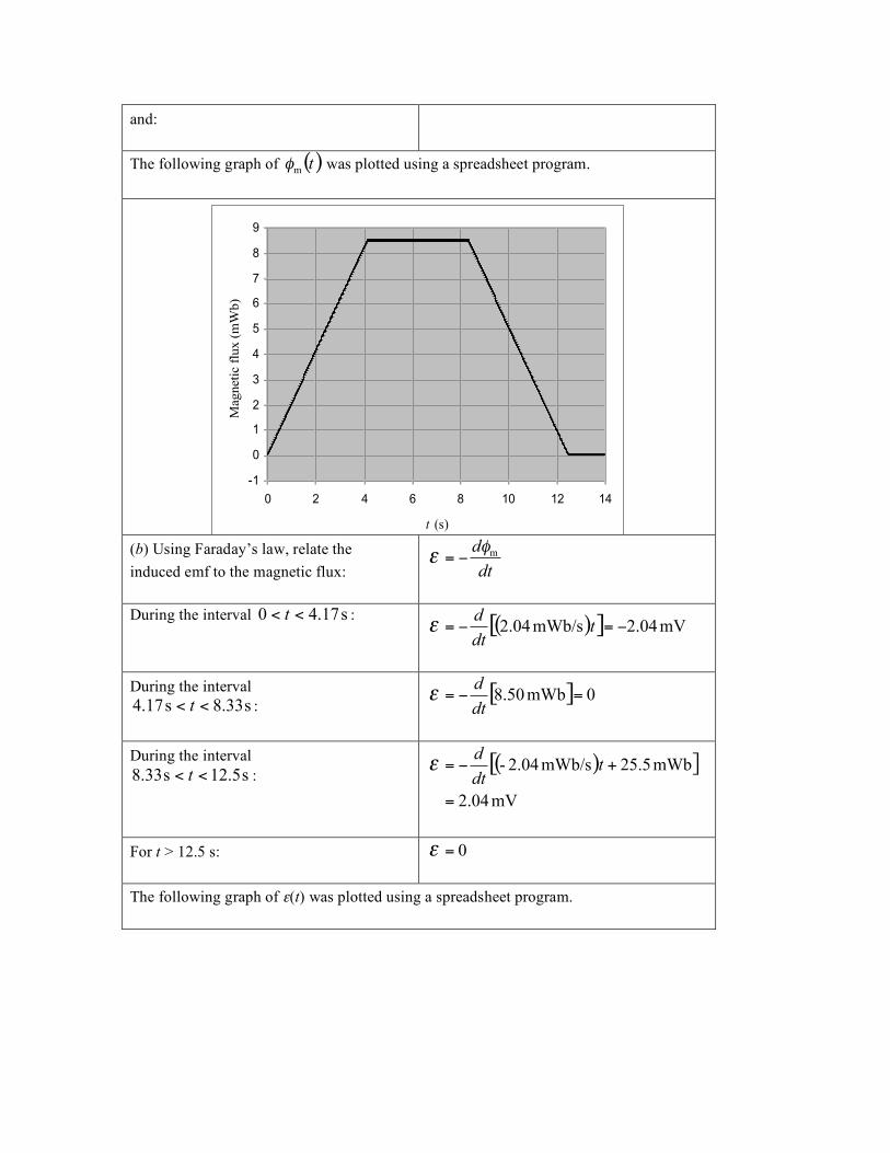
and: The following graph of ( )t
m! was plotted using a spreadsheet program.
-1
0
1
2
3
4
5
6
7
8
9
0 2 4 6 8 10 12 14
t (s)
Magneti
c f
lux (
mW
b)
(b) Using Faraday’s law, relate the induced emf to the magnetic flux:
dt
dm!
" #=
During the interval s17.40 << t : ( )[ ] mV04.2mWb/s04.2 !=!= t
dt
d"
During the interval
s33.8s17.4 << t :
[ ] 0mWb50.8 =!=dt
d"
During the interval
s5.12s33.8 << t :
( )[ ]
mV04.2
mWb5.25mWb/s2.04-
=
+!= tdt
d"
For t > 12.5 s: 0=!
The following graph of ε(t) was plotted using a spreadsheet program.

-2.5
-2.0
-1.5
-1.0
-0.5
0.0
0.5
1.0
1.5
2.0
2.5
0 2 4 6 8 10 12 14
t (s)
em
f (V
)
Problem 28.85 The AC generator
Picture the Problem We can apply Faraday’s law and the definition of magnetic flux to derive an expression for the induced emf in the coil (potential difference between the slip rings). In part (b) we can solve this equation for ω under the given conditions. (a) Use Faraday’s law to express the induced emf:
dt
dm!" #=
Using the definition of magnetic flux, relate the magnetic flux through the loop to its angular velocity:
( ) tNBAt !" cosm
=
Substitute to obtain:
[ ]
( )
tNBab
tNBab
tNBAdt
d
!!
!!
!"
sin
sin
cos
=
##=
#=

(b) Express the condition under which ε = εmax:
1sin =t!
Solve for and evaluate ω under this condition:
( )( )( )( )
rad/s275
m0.02m0.01T21000
V110
max
=
=
=NBab
!"


![Modeling of Electromagnetic Absorption/Scattering Problems ...then deduced from the electric and magnetic fields, see e.g. [2]. The second class of problems motivating this work deals](https://img.dokumen.tips/doc/110x75/61474e03afbe1968d379f92c/modeling-of-electromagnetic-absorptionscattering-problems-then-deduced-from.jpg)


![Chapter 26 The Magnetic Field - North Hunterdon … 26 The Magnetic Field Conceptual Problems 1 •[SSM] When the axis of a cathode-ray tube is horizontal in a region in which there](https://img.dokumen.tips/doc/110x75/5b248a6c7f8b9aa00a8b4efd/chapter-26-the-magnetic-field-north-hunterdon-26-the-magnetic-field-conceptual.jpg)