Embed Size (px)
Citation preview
2020
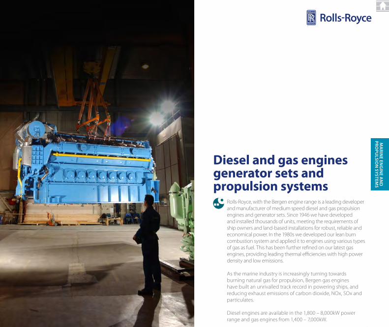
Rolls-Royce, with the Bergen engine range is a leading developer and manufacturer of medium speed diesel and gas propulsion engines and generator sets. Since 1946 we have developed and installed thousands of units, meeting the requirements of ship owners and land-based installations for robust, reliable and economical power. In the 1980s we developed our lean burn combustion system and applied it to engines using various types of gas as fuel. This has been further refined on our latest gas engines, providing leading thermal efficiencies with high power density and low emissions.
As the marine industry is increasingly turning towards burning natural gas for propulsion, Bergen gas engines have built an unrivalled track record in powering ships, and reducing exhaust emissions of carbon dioxide, NOx, SOx and particulates.
Diesel engines are available in the 1,800 – 8,000kW power range and gas engines from 1,400 – 7,000kW.
Diesel and gas enginesgenerator sets and propulsion systems
21
Ma
rine en
gin
e an
D
prOpu
LSiOn
SySTeMS
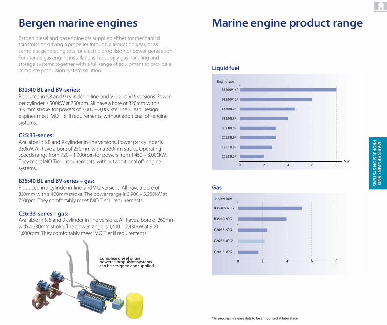
B32:40 BL and BV-series: Produced in 6,8 and 9 cylinder in-line, and V12 and V16 versions. Power per cylinder is 500kW at 750rpm. All have a bore of 320mm with a 400mm stroke, for powers of 3,000 – 8,000kW. The ‘Clean Design’ engines meet IMO Tier II requirements, without additional off-enginesystems.
C25:33-series: Available in 6,8 and 9 cylinder in-line versions. Power per cylinder is 330kW. All have a bore of 250mm with a 330mm stroke. Operating speeds range from 720 – 1,000rpm for powers from 1,460 – 3,000kW.They meet IMO Tier II requirements, without additional off-engine systems.
B35:40 BL and BV-series – gas: Produced in 9 cylinder in-line, and V12 versions. All have a bore of 350mm with a 400mm stroke. The power range is 3,900 – 5,250kW at 750rpm. They comfortably meet IMO Tier III requirements.
C26:33-series – gas: Available in 6, 8 and 9 cylinder in-line versions. All have a bore of 260mm with a 330mm stroke. The power range is 1,400 – 2,430kW at 900 – 1,000rpm. They comfortably meet IMO Tier III requirements.
Bergen marine enginesBergen diesel and gas engine are supplied either for mechanical transmission driving a propeller through a reduction gear, or as complete generating sets for electric propulsion or power generation. For marine gas engine installations we supply gas handling and storage systems together with a full range of equipment to provide a complete propulsion system solution.
complete diesel or gas powered propulsion systems can be designed and supplied.
2222
Marine engine product range
B35:40V12PG
C26:33L9PG
C26:33L8PG*
C26: 3L6PG
B35:40L9PG
0 2 4 6 8
Liquid fuel
gas
L qui f el
Engine type
B32:40V16P
B32:40V12P
B32:40L9P
B32:40L8P
B32:40L6P
C25:33L9P
C25:33L8P
C25:33L6P
MW 0 2 4 6 8
Eng
C26:3 9P
C26:33L8P
* In progress - release date to be announced at later stage
23
Ma
rine en
gin
e an
D
prOpu
LSiOn
SySTeMS
* Bergen c26:33 gas engines have obtained united States Environmental Protection Agency (EPA) tier 3 certification.
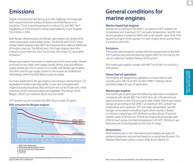
emissionsEngine manufacturers are facing up to the challenge of increasingly strict requirements for exhaust emissions and Rolls-Royce is no exception. There is growing pressure to reduce CO
2 and IMO Tier II
regulations on NOx emissions will be superseded by much tougher Tier III limits in 2016.
Both Bergen diesel engines and Bergen gas engines are designed for marine propulsion and auxiliary duties. The B32:40 and C25:33 ‘Clean Design’ diesel engines meet IMO Tier II requirements without additional off-engine clean up. The B35:40 and C26:33 gas engines have NOx emissions lower than the strict Tier III limits with lower CO
2 equivalent
emissions.*
Bergen gas engines have been in marine service for seven years. Vessels as diverse as roro ships, feed supply vessels, ferries, tugs and offshore supply vessels are now in-service or on order with Bergen gas engines. Gas tanks and the gas supply system to the engine are established technology, within the Rolls-Royce scope of supply.
For many applications the gas engine is becoming a natural choice. CO2
equivalent emissions are reduced by 22 per cent compared with engines burning liquid fuel, NOx emissions are cut by 92 per cent, while emissions of SOx and particulates are negligible. The design of the Bergen C26:33 cuts methane slip to very low levels.
SCR Systems can be included into Rolls-Royce scope of supply.
nOx emission for Bergen engines
2424
Marine liquid fuel enginesRatings are according to ISO 3046-1, at maximum 45°C ambient air temperature and maximum 32°C sea water temperature. Specific fuel oil consumption is based on MDO with a net calorific value of 42.7 MJ/kg and no engine driven pumps. For each engine driven pump, there is a need to add 0.5%.
emissionsThe marine diesel engines comply with the requirements of the IMO Tier II without any external cleaning system. IMO Tier III is met by the use of a Selective Catalytic Reactor (SCR) system.
The marine gas engines comply with IMO Tier III with no need for a SCR system.
heavy fuel oil operationThe engines are designed for operation on heavy fuel oil with viscosity up to 700 cSt at 50°C ISO 8217 RMK77. Ratings will be specified subject to type of application.
Marine gas enginesThe marine gas engines give the following reductions in emissions compared with diesels IMO Tier II: 92% NOx, net 22% greenhouse gases and close to zero SOx and particulate matter. Marine gas engine ratings are according to ISO 3046-1, at maximum 45°C ambient air temperature and maximum 32°C sea water temperature. Specific fuel gas consumption excluding engine driven pumps is based on reference natural gas with Methane number above 70 and net calorific value of 36 MJ/nm3. If there are engine driven pumps, add 0.5% for each pump. Gas feed temperature is 20-40°C. Minimum gas feed pressure to Gas Regulating Unit to be 4.5 barg.
DimensionsAll dimensions are in mm. Dimensions and weights are given for guidance purposes only and are based on a typical specification. For detailed information please contact Rolls-Royce Marine AS.
general conditions for marine engines
Note : due to continuous development, some data may change without notice.
25
Ma
rine en
gin
e an
D
prOpu
LSiOn
SySTeMS
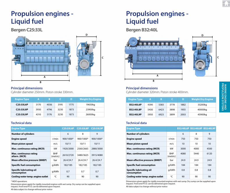
propulsion engines - Liquid fuel
principal dimensionsCylinder diameter 250mm. Piston stroke 330mm.
Technical data
Engine type A B C D Weight Dry Engine
C25:33L6P 3170 4036 3195 1775 19650kg
C25:33L8P 3930 4796 3230 1873 23900kg
C25:33L9P 4310 5176 3230 1873 26000kg
Engine type C25:33L6P C25:33L8P C25:33L9P
Number of cylinders 6 8 9
Engine speed r/min 900/1000* 900/1000* 900/1000*
Mean piston speed m/s 10/11 10/11 10/11
Max. continuous rating (MCR) kW 1920/2000 2560/2665 2880/3000
Max. continuous rating altern. (MCR)
BHP (metric) 2610/2720 3480/3625 3915/4080
Mean effective pressure (BMEP) bar 26.4/24.7 26.4/24.7 26.4/24.7
Specific fuel consumption g/kWh 182/185 182/185 182/185
Specific lubricating oil consumption g/kWh 0.7 0.7 0.7
Cooling water temp. engine outlet oc 90 90 90
* Mdo operations dimensions given apply for rigidly mounted engines with wet sump. dry sump can be supplied upon request. Front end P.t.o. can be delivered upon request.All data subject to change without prior notice
a
B
C
D
Bergen C25:33L
2626
Engine type B32:40L6P B32:40L8P B32:40L9P
Number of cylinders 6 8 9
Engine speed r/min 750 750 750
Mean piston speed m/s 10 10 10
Max. continuous rating (MCR) kW 3000 4000 4500
Max. continuous rating (MCR) BHP (metric)
4080 5440 6120
Mean effective pressure (BMEP) bar 24.9 24.9 24.9
Specific fuel consumption g/kWh 184 184 184
Specific lubricating oil consumption
g/kWh 0.8 0.8 0.8
Cooling water temp. engine outlet oc 90 90 90
propulsion engines - Liquid fuel
principal dimensionsCylinder diameter 320mm. Piston stroke 400mm.
Technical data
Engine type A B C D Weight Dry Engine
B32:40L6P 4390 5383 3778 1882 33200kg
B32:40L8P 5430 6423 3898 1955 40000kg
B32:40L9P 5950 6923 3899 2003 45900kg
dimensions given apply for rigidly mounted engines with wet sump. dry sump can be supplied upon request. Front end P.t.o. can be delivered upon request.All data subject to change without prior notice
a
C
D
B
Bergen B32:40L
27
Ma
rine en
gin
e an
D
prOpu
LSiOn
SySTeMS
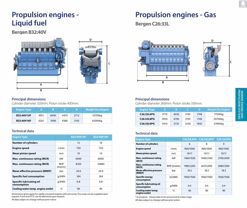
propulsion engines - Liquid fuelBergen B32:40V
principal dimensionsCylinder diameter 320mm. Piston stroke 400mm.
Technical data
Engine type A B C D Weight Dry Engine
B32:40V12P 4951 6040 4470 2712 53700kg
B32:40V16P 6201 7698 4380 3192 62900kg
Engine type B32:40V12P B32:40V16P
Number of cylinders 12 16
Engine speed r/min 750 750
Mean piston speed m/s 10 10
Max. continuous rating (MCR) kW 6000 8000
Max. continuous rating (MCR) BHP (metric)
8160 10880
Mean effective pressure (BMEP) bar 24.9 24.9
Specific fuel consumption g/kWh 184 184
Specific lubricating oil consumption
g/kWh 0.8 0.8
Cooling water temp. engine outlet oc 90 90
dimensions given apply for rigidly mounted engines with wet sump. dry sump can be supplied upon request. Front end P.t.o. can be delivered upon request.All data subject to change without prior notice
a
C
D
B
2828
propulsion engines - gasBergen C26:33L
a
B
D
C
principal dimensionsCylinder diameter 260mm. Piston stroke 330mm.
Technical data
Engine type a B C D Weight Dry engine
C26:33L6PG 3170 4036 3195 1748 17500kg
C26:33L8PG 3930 4796 3195 1748 20700kg
C26:33L9PG 4310 5176 3230 1842 23900kg
Engine type C26:33L6PG C26:33L8PG* C26:33L9PG
Number of cylinders 6 8 9
Engine speed r/min 900/1000 900/1000 900/1000
Mean piston speed m/s 10/11 10/11 10/11
Max. continuous rating (MCR)
kW 1460/1620 1940/2160 2190/2430
Max. continuous rating (MCR) BHP (metric) 1985/2205 2675/2935 2980/3305
Mean effective pressure (BMEP)
bar 18.5 18.5 18.5
Specific energy consumption
kJ/kWh 7450/7500 7450/7500 7450/7500
Specific lubricating oil consumption g/kWh 0.4 0.4 0.4
Cooling water temp. engine outlet
oc 90 90 90
* In progress - release date to be announced at a later stageAll data subject to change without prior notice
29
Ma
rine en
gin
e an
D
prOpu
LSiOn
SySTeMS
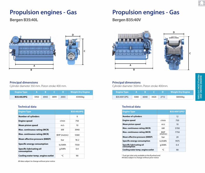
propulsion engines - gasBergen B35:40L
Engine type A B C D Weight Dry Engine
B35:40L9PG 5950 6943 3899 2003 45900kg
All data subject to change without prior notice
principal dimensionsCylinder diameter 350 mm. Piston stroke 400 mm.
Technical data
Engine type B35:40L9PG
Number of cylinders 9
Engine speed r/min 750
Mean piston speed m/s 10
Max. continuous rating (MCR) kW 3940
Max. continuous rating (MCR) BHP (metric) 5360
Mean effective pressure (BMEP) bar 18.2
Specific energy consumption kJ/kWh 7550
Specific lubricating oil consumption
g/kWh 0.4
Cooling water temp. engine outlet oc 90
C
D
a
B
3030
propulsion engines - gasBergen B35:40V
a
B
principal dimensionsCylinder diameter 350mm. Piston stroke 400mm.
D
C
Engine type A B C D Weight Dry Engine
B35:40V12PG 5080 6040 4420 2712 58000kg
Technical data
Engine type B35:40V12PG*
Number of cylinders 12
Engine speed r/min 750
Mean piston speed m/s 10
Max. continuous rating (MCR) kW 5700
Max. continuous rating (MCR) BHP (metric)
7750
Mean effective pressure (BMEP) bar 20
Specific energy consumption kJ/kWh 7475
Specific lubricating oil consumption
g/kWh 0.4
Cooling water temp. engine outlet oc 90
* Fuel gas inlet only available at the flywheel endAll data subject to change without prior notice
31
Ma
rine en
gin
e an
D
prOpu
LSiOn
SySTeMS
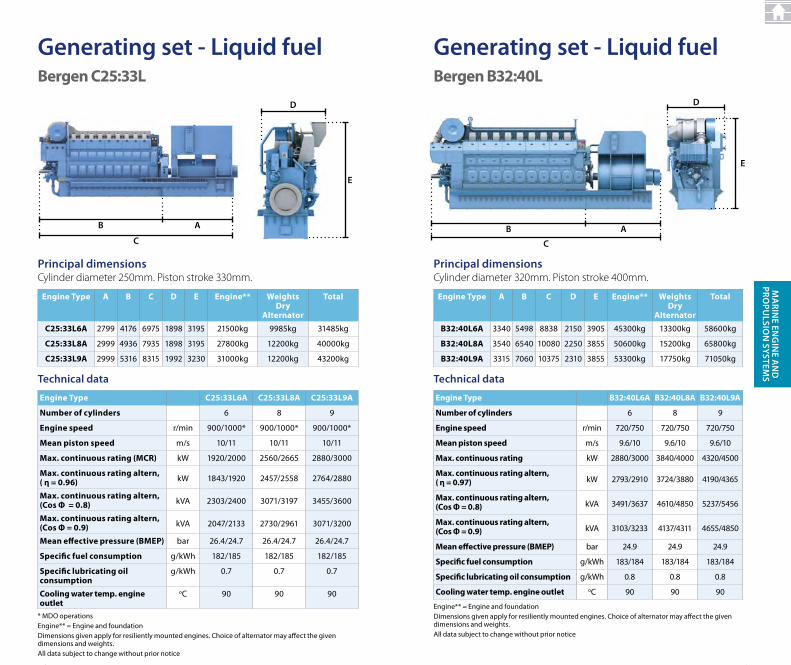
generating set - Liquid fuelBergen C25:33L
Technical data
Engine type A B C D E Engine** Weights Dry
Alternator
total
C25:33L6A 2799 4176 6975 1898 3195 21500kg 9985kg 31485kg
C25:33L8A 2999 4936 7935 1898 3195 27800kg 12200kg 40000kg
C25:33L9A 2999 5316 8315 1992 3230 31000kg 12200kg 43200kg
* Mdo operationsEngine** = Engine and foundationdimensions given apply for resiliently mounted engines. choice of alternator may affect the given dimensions and weights. All data subject to change without prior notice
principal dimensionsCylinder diameter 250mm. Piston stroke 330mm.
Engine type C25:33L6A C25:33L8A C25:33L9A
Number of cylinders 6 8 9
Engine speed r/min 900/1000* 900/1000* 900/1000*
Mean piston speed m/s 10/11 10/11 10/11
Max. continuous rating (MCR) kW 1920/2000 2560/2665 2880/3000
Max. continuous rating altern,( η = 0.96) kW 1843/1920 2457/2558 2764/2880
Max. continuous rating altern, (Cos Ф = 0.8) kVA 2303/2400 3071/3197 3455/3600
Max. continuous rating altern, (Cos Ф = 0.9) kVA 2047/2133 2730/2961 3071/3200
Mean effective pressure (BMEP) bar 26.4/24.7 26.4/24.7 26.4/24.7
Specific fuel consumption g/kWh 182/185 182/185 182/185
Specific lubricating oil consumption
g/kWh 0.7 0.7 0.7
Cooling water temp. engine outlet
oc 90 90 90
B
C
a
D
e
3232
generating set - Liquid fuelBergen B32:40L
C
aB
D
e
principal dimensionsCylinder diameter 320mm. Piston stroke 400mm.
Technical data
Engine type A B C D E Engine** Weights Dry
Alternator
total
B32:40L6A 3340 5498 8838 2150 3905 45300kg 13300kg 58600kg
B32:40L8A 3540 6540 10080 2250 3855 50600kg 15200kg 65800kg
B32:40L9A 3315 7060 10375 2310 3855 53300kg 17750kg 71050kg
Engine** = Engine and foundationdimensions given apply for resiliently mounted engines. choice of alternator may affect the given dimensions and weights. All data subject to change without prior notice
Engine type B32:40L6A B32:40L8A B32:40L9A
Number of cylinders 6 8 9
Engine speed r/min 720/750 720/750 720/750
Mean piston speed m/s 9.6/10 9.6/10 9.6/10
Max. continuous rating kW 2880/3000 3840/4000 4320/4500
Max. continuous rating altern, ( η = 0.97) kW 2793/2910 3724/3880 4190/4365
Max. continuous rating altern, (Cos Ф = 0.8) kVA 3491/3637 4610/4850 5237/5456
Max. continuous rating altern, (Cos Ф = 0.9) kVA 3103/3233 4137/4311 4655/4850
Mean effective pressure (BMEP) bar 24.9 24.9 24.9
Specific fuel consumption g/kWh 183/184 183/184 183/184
Specific lubricating oil consumption g/kWh 0.8 0.8 0.8
Cooling water temp. engine outlet oc 90 90 90
33
Ma
rine en
gin
e an
D
prOpu
LSiOn
SySTeMS
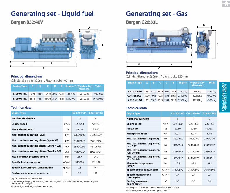
generating set - Liquid fuelBergen B32:40V
Technical data
Engine type A B C D E Engine** Weights Dry Alternator
total
B32:40V12A 4095 6366 10461 2712 4751 72616kg 29400kg 102016kg
B32:40V16A 3875 7861 11736 3194 4584 83500kg 23500kg 107000kg
Engine** = Engine and foundationdimensions given apply for resiliently mounted engines. choice of alternator may affect the given dimensions and weights. All data subject to change without prior notice
principal dimensionsCylinder diameter 320mm. Piston stroke 400mm.
Engine type B32:40V12A B32:40V16A
Number of cylinders 12 16
Engine speed r/min 720/750 720/750
Mean piston speed m/s 9.6/10 9.6/10
Max. continuous rating (MCR) kW 5760/6000 7680/8000
Max. continuous rating altern, ( η = 0.97) kW 5587/5820 7449/7760
Max. continuous rating altern, (Cos Ф = 0.8) kVA 6983/7275 9311/9700
Max. continuous rating altern, (Cos Ф = 0.9) kVA 6207/6466 8276/8622
Mean effective pressure (BMEP) bar 24.9 24.9
Specific fuel consumption g/kWh 183/184 183/184
Specific lubricating oil consumption g/kWh 0.8 0.8
Cooling water temp. engine outlet oc 90 90
a B
D
C
e
3434
generating set - gasBergen C26:33L
C
Ba
D
e
principal dimensionsCylinder diameter 260mm. Piston stroke 330mm.
Technical data
Engine type A B C D E Engine Weights Dry Alternator
total
C26:33L6AG 2799 4176 6975 1898 3195 21500kg 9985kg 31485kg
C26:33L8AG* 2999 4936 7935 1898 3195 27800kg 12200kg 40000kg
C26:33L9AG 2999 5316 8315 1992 3230 31000kg 12200kg 43200kg
Engine type C26:33L6AG C26:33L8AG* C26:33L9AG
Number of cylinders 6 8 9
Engine speed r/min 900/1000 900/1000 900/1000
Frequency hz 60/50 60/50 60/50
Mean piston speed m/s 10/11 10/11 10/11
Max. continuous rating (MCR) kW 1460/1620 1940/2160 2190/2430
Max. continuous rating altern,( η = 0.96) kW 1401/1555 1840/2050 2102/2332
Max. continuous rating altern, (Cos Ф = 0.8) kVA 1751/1943 2300/2563 2627/2915
Max. continuous rating altern, (Cos Ф = 0.9) kVA 1556/1727 2044/2278 2335/2591
Mean effective pressure (BMEP)
bar 18.5 18.5 18.5
Specific energy consumption g/kWh 7450/7500 7450/7500 7450/7500
Specific lubricating oil consumption
g/kWh 0.4 0.4 0.4
Cooling water temp. engine outlet
oc 90 90 90
* In progress - release date to be announced at a later stageAll data subject to change without prior notice
35
Ma
rine en
gin
e an
D
prOpu
LSiOn
SySTeMS
Engine type A B C D E Engine Weights Dry Alternator
total
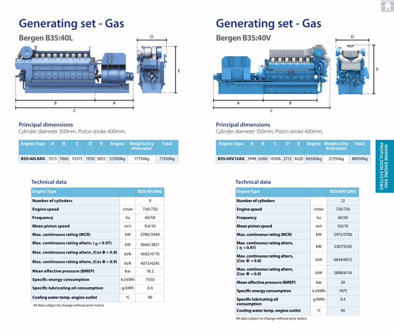
B35:40L9AG 3315 7060 10375 1050 3855 53300kg 17750kg 71050kg
Technical data
Engine type B35:40L9AG
Number of cylinders 9
Engine speed r/min 720/750
Frequency hz 60/50
Mean piston speed m/s 9.6/10
Max. continuous rating (MCR) kW 3780/3940
Max. continuous rating altern, ( η = 0.97) kW 3666/3821
Max. continuous rating altern, (Cos Ф = 0.8) kVA 4582/4776
Max. continuous rating altern, (Cos Ф = 0.9) kVA 4073/4245
Mean effective pressure (BMEP) bar 18.2
Specific energy consumption kJ/kWh 7550
Specific lubricating oil consumption g/kWh 0.4
Cooling water temp. engine outlet oc 90
c
AB
d
E
principal dimensionsCylinder diameter 350mm. Piston stroke 400mm.
All data subject to change without prior notice
generating set - gasBergen B35:40L
3636
generating set - gas
principal dimensionsCylinder diameter 350mm. Piston stroke 400mm.
Engine type A B C D E Engine Weights Dry Alternator
total
B35:40V12AG 3948 6366 10306 2712 4620 66500kg 21550kg 88050kg
Technical data
Engine type B35:40V12AG
Number of cylinders 12
Engine speed r/min 720/750
Frequency hz 60/50
Mean piston speed m/s 9.6/10
Max. continuous rating (MCR) kW 5472/5700
Max. continuous rating altern,( η = 0.97) kW 5307/5530
Max. continuous rating altern, (Cos Ф = 0.8) kVA 6634/6912
Max. continuous rating altern, (Cos Ф = 0.9) kVA 5898/6114
Mean effective pressure (BMEP) bar 20
Specific energy consumption kJ/kWh 7475
Specific lubricating oil consumption
g/kWh 0.4
Cooling water temp. engine outlet oc 90
c
BA
d
E
All data subject to change without prior notice
Bergen B35:40V
37
Ma
rine en
gin
e an
D
prOpu
LSiOn
SySTeMS
d
AZP
c
S
propulsion systems
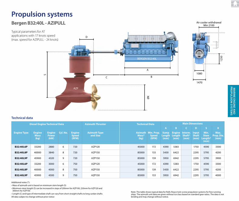
Typical parameters for AT applications with 17 knots speed (max. speed for AZIPULL - 24 knots)
Bergen B32:40L - AZIPULL
Additional notes (*):• Mass of azimuth unit is based on minimum stem length (S)• Minimum stem length (S) can be increased in steps of 200mm for AZP100, 250mm for AZP120 and
300mm for AZP150• Length (C) and type of intermediate shaft can vary from short straight shafts to long cardan shafts
Diesel Engine technical Data Azimuth thruster technical Data Main Dimensions
A B C D S K
Engine type Engine Mass (kg)
Engine Power (kW)
Cyl. No. Engine Speed (RPM)
Azimuth type and Size
Azimuth Mass*
(kg)
Min. Prop. Speed (RPM)
Sump Length (mm)
E gine Length (mm)
Interm. Shaft* (mm)
Input Shaft (mm)
Min. Stem
Length* (mm)
Max. Prop. Dia.
(mm)
B32:40L6P 33200 2880 6 720 AZP120 45000 172 4390 5383 1750 4590 3300
B32:40L8P 40000 3840 8 720 AZP150 85000 133 5430 6422 2295 5795 4200
B32:40L9P 45900 4320 9 720 AZP150 85000 159 5950 6942 2295 5795 3900
B32:40L6P 33200 3000 6 750 AZP120 45000 172 4390 5383 1750 4590 3300
B32:40L8P 40000 4000 8 750 AZP150 85000 139 5430 6422 2295 5795 4200
B32:40L9P 45900 4500 9 750 AZP150 85000 153 5950 6942 2295 5795 4000
All data subject to change without prior notice
Technical data
3838
BERGEN B32:40L
B
A
ØK
1250
1080
Air cooler withdrawalMin 2100
1470
Note: the table shows typical data for rolls-royce twin screw propulsion systems for free running ships. The azimuth unit data are given without ice class based on standard gear ratios. The data is not binding and may change without notice.
Diesel Engine technical Data Azimuth thruster technical Data Main Dimensions
A B C D S K
Engine type Engine Mass (kg)
Engine Power (kW)
Cyl. No. Engine Speed (RPM)
Azimuth type and Size
Azimuth Mass*
(kg)
Min. Prop. Speed (RPM)
Sump Length (mm)
Engine Length (mm)
Interm. Shaft* (mm)
Input Shaft (mm)
Min. Stem
Length* (mm)
Max. Prop. Dia.
(mm)
B32:40L6P 33200 2880 6 720 AZP120 45000 172 4390 5383 1750 4590 3300
B32:40L8P 40000 3840 8 720 AZP150 85000 133 5430 6422 2295 5795 4200
B32:40L9P 45900 4320 9 720 AZP150 85000 159 5950 6942 2295 5795 3900
B32:40L6P 33200 3000 6 750 AZP120 45000 172 4390 5383 1750 4590 3300
B32:40L8P 40000 4000 8 750 AZP150 85000 139 5430 6422 2295 5795 4200
B32:40L9P 45900 4500 9 750 AZP150 85000 153 5950 6942 2295 5795 4000
39
Ma
rine en
gin
e an
D
prOpu
LSiOn
SySTeMS
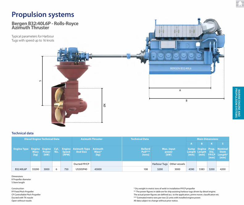
Typical parameters for Harbour Tugs with speed up to 16 knots
Bergen B32:40L6P - Rolls-Royce Azimuth thruster
Diesel Engine technical Data Azimuth thruster technical Data Main Dimensions
A B K S
Engine type Engine Mass [kg]
Engine Power [kW]
Cyl. No.
Engine Speed [RPM]
Azimuth type And Size
Azimuth Mass*
[kg]
Bollard Pull***[tons]
Max. input power [kW]
Sump Length
[mm]
Engine Length
[mm]
Prop. Dia.
FP/CP [mm]
NominalStem
Length* [mm]
ducted FP/cP Harbour tugs other vessels
B32:40L6P 33200 3000 6 750 uS305P40 43000 108 3200 3000 4390 5383 3200 4200
ØK
S
propulsion systems
Technical data
dimensionsK Propeller diameterS Stem length
constructionFP Fixed Pitch PropellercP controllable Pitch PropellerDucted with TK-nozzleOpen without nozzle.
4040
* dry weight in metric tons of weld-in installation FP/cP propeller** the power figures in table are for ship assisting harbour tugs driven by diesel engine. the actual power figures are defined acc. to the application, prime mover, classification etc*** Estimated metric tons per two (2) units with installed engine power.All data subject to change without prior notice.
Diesel Engine technical Data Azimuth thruster technical Data Main Dimensions
A B K S
Engine type Engine Mass [kg]
Engine Power [kW]
Cyl. No.
Engine Speed [RPM]
Azimuth type And Size
Azimuth Mass*
[kg]
Bollard Pull***[tons]
Max. input power [kW]
Sump Length
[mm]
Engine Length
[mm]
Prop. Dia.
FP/CP [mm]
NominalStem
Length* [mm]
ducted FP/cP Harbour tugs other vessels
B32:40L6P 33200 3000 6 750 uS305P40 43000 108 3200 3000 4390 5383 3200 4200
B
A
BERGEN B32:40L6
41
Ma
rine en
gin
e an
D
prOpu
LSiOn
SySTeMS
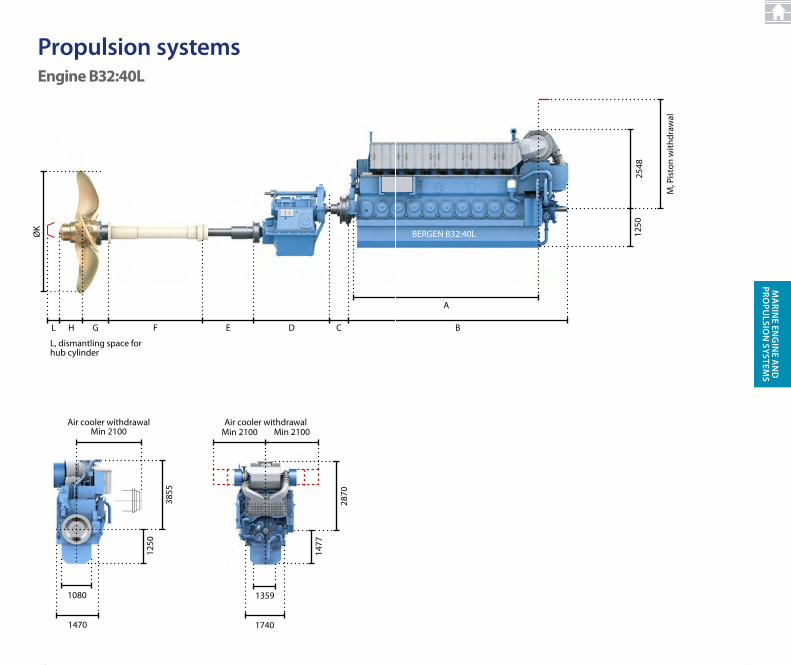
Engine B32:40L
propulsion systems
1477
2870
1359
Air cooler withdrawal
1740
Min 2100 Min 2100
cGHL E dF
ØK
L, dismantling space for hub cylinder
3855
1250
1080
Air cooler withdrawalMin 2100
1470
4242
BERGEN B32:40L
M, P
isto
n w
ithdr
awal
2548
1250
B
A
43
Ma
rine en
gin
e an
D
prOpu
LSiOn
SySTeMS
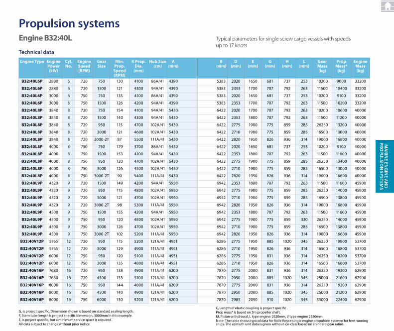
Engine B32:40L
Engine type Engine Power (kW)
Cyl. No.
Engine Speed (RPM)
Gear Size
Min. Prop.
Speed(RPM)
K Prop. Dia.
(mm)
Hub Size(cm)
A(mm)
B(mm)
D(mm)
E(mm)
G(mm)
H(mm)
L(mm)
Gear Mass(kg)
Prop Mass*
(kg)
Engine Mass (kg)
B32:40L6P 2880 6 720 750 130 4100 86A/41 4390 5383 2020 1650 681 737 253 10200 9000 33200
B32:40L6P 2880 6 720 1500 121 4300 94A/41 4390 5383 2353 1700 707 792 263 11500 10400 33200
B32:40L6P 3000 6 750 750 135 4100 86A/41 4390 5383 2020 1650 681 737 253 10200 9100 33200
B32:40L6P 3000 6 750 1500 126 4200 94A/41 4390 5383 2353 1700 707 792 263 11500 10200 33200
B32:40L8P 3840 8 720 750 154 4100 94A/41 5430 6422 2020 1700 707 792 263 10200 10600 40000
B32:40L8P 3840 8 720 1500 140 4300 94A/41 5430 6422 2353 1800 707 792 263 11500 11200 40000
B32:40L8P 3840 8 720 950 115 4700 102A/41 5430 6422 2775 1900 775 859 285 26250 13200 40000
B32:40L8P 3840 8 720 3000 121 4600 102A/41 5430 6422 2710 1900 775 859 285 16500 13000 40000
B32:40L8P 3840 8 720 3000-2t 87 5500 111A/41 5430 6422 2820 1950 826 936 314 19000 16800 40000
B32:40L8P 4000 8 750 750 179 3700 86A/41 5430 6422 2020 1650 681 737 253 10200 9100 40000
B32:40L8P 4000 8 750 1500 153 4100 94A/41 5430 6422 2353 1800 707 792 263 11500 11000 40000
B32:40L8P 4000 8 750 950 120 4700 102A/41 5430 6422 2775 1900 775 859 285 26250 13400 40000
B32:40L8P 4000 8 750 3000 126 4500 102A/41 5430 6422 2710 1900 775 859 285 16500 13000 40000
B32:40L8P 4000 8 750 3000-2t 90 5400 111A/41 5430 6422 2820 1950 826 936 314 19000 16600 40000
B32:40L9P 4320 9 720 1500 149 4200 94A/41 5950 6942 2353 1800 707 792 263 11500 11600 45900
B32:40L9P 4320 9 720 950 115 4800 102A/41 5950 6942 2775 1900 775 859 285 26250 14000 45900
B32:40L9P 4320 9 720 3000 121 4700 102A/41 5950 6942 2710 1900 775 859 285 16500 13800 45900
B32:40L9P 4320 9 720 3000-2t 98 5300 111A/41 5950 6942 2820 1950 826 936 314 19000 16800 45900
B32:40L9P 4500 9 750 1500 155 4200 94A/41 5950 6942 2353 1800 707 792 263 11500 11600 45900
B32:40L9P 4500 9 750 950 120 4800 102A/41 5950 6942 2775 1900 775 859 330 26250 14000 45900
B32:40L9P 4500 9 750 3000 126 4700 102A/41 5950 6942 2710 1900 775 859 285 16500 13800 45900
B32:40L9P 4500 9 750 3000-2t 102 5200 111A/41 5950 6942 2820 1950 826 936 314 19000 16600 45900
B32:40V12P 5765 12 720 950 115 5200 121A/41 4951 6286 2775 1950 885 1020 345 26250 19800 53700
B32:40V12P 5765 12 720 3000 129 4900 111A/41 4951 6286 2710 1950 826 936 314 16500 16800 53700
B32:40V12P 6000 12 750 950 120 5100 111A/41 4951 6286 2775 1950 831 936 314 26250 18200 53700
B32:40V12P 6000 12 750 3000 135 4800 111A/41 4951 6286 2710 1950 826 936 314 16500 16800 53700
B32:40V16P 7680 16 720 950 138 4900 111A/41 6200 7870 2775 2000 831 936 314 26250 19200 62900
B32:40V16P 7680 16 720 4500 133 5100 121A/41 6200 7870 2950 2000 885 1020 345 25000 21600 62900
B32:40V16P 8000 16 750 950 144 4800 111A/41 6200 7870 2775 2000 831 936 314 26250 19200 62900
B32:40V16P 8000 16 750 4500 140 4900 121A/41 6200 7870 2950 2000 885 1020 345 25000 21200 62900
B32:40V16P 8000 16 750 6000 130 5200 121A/41 6200 7870 2985 2050 910 1020 345 33000 22400 62900
G, is project specific. dimension shown is based on standard sealing length.F, Stern tube length is project specific dimension, 3000mm in this example.E, is project specific, but a minimum service space is required.All data subject to change without prior notice
Technical data
propulsion systems
4444
Engine type Engine Power (kW)
Cyl. No.
Engine Speed (RPM)
Gear Size
Min. Prop.
Speed(RPM)
K Prop. Dia.
(mm)
Hub Size(cm)
A(mm)
B(mm)
D(mm)
E(mm)
G(mm)
H(mm)
L(mm)
Gear Mass(kg)
Prop Mass*
(kg)
Engine Mass (kg)
B32:40L6P 2880 6 720 750 130 4100 86A/41 4390 5383 2020 1650 681 737 253 10200 9000 33200
B32:40L6P 2880 6 720 1500 121 4300 94A/41 4390 5383 2353 1700 707 792 263 11500 10400 33200
B32:40L6P 3000 6 750 750 135 4100 86A/41 4390 5383 2020 1650 681 737 253 10200 9100 33200
B32:40L6P 3000 6 750 1500 126 4200 94A/41 4390 5383 2353 1700 707 792 263 11500 10200 33200
B32:40L8P 3840 8 720 750 154 4100 94A/41 5430 6422 2020 1700 707 792 263 10200 10600 40000
B32:40L8P 3840 8 720 1500 140 4300 94A/41 5430 6422 2353 1800 707 792 263 11500 11200 40000
B32:40L8P 3840 8 720 950 115 4700 102A/41 5430 6422 2775 1900 775 859 285 26250 13200 40000
B32:40L8P 3840 8 720 3000 121 4600 102A/41 5430 6422 2710 1900 775 859 285 16500 13000 40000
B32:40L8P 3840 8 720 3000-2t 87 5500 111A/41 5430 6422 2820 1950 826 936 314 19000 16800 40000
B32:40L8P 4000 8 750 750 179 3700 86A/41 5430 6422 2020 1650 681 737 253 10200 9100 40000
B32:40L8P 4000 8 750 1500 153 4100 94A/41 5430 6422 2353 1800 707 792 263 11500 11000 40000
B32:40L8P 4000 8 750 950 120 4700 102A/41 5430 6422 2775 1900 775 859 285 26250 13400 40000
B32:40L8P 4000 8 750 3000 126 4500 102A/41 5430 6422 2710 1900 775 859 285 16500 13000 40000
B32:40L8P 4000 8 750 3000-2t 90 5400 111A/41 5430 6422 2820 1950 826 936 314 19000 16600 40000
B32:40L9P 4320 9 720 1500 149 4200 94A/41 5950 6942 2353 1800 707 792 263 11500 11600 45900
B32:40L9P 4320 9 720 950 115 4800 102A/41 5950 6942 2775 1900 775 859 285 26250 14000 45900
B32:40L9P 4320 9 720 3000 121 4700 102A/41 5950 6942 2710 1900 775 859 285 16500 13800 45900
B32:40L9P 4320 9 720 3000-2t 98 5300 111A/41 5950 6942 2820 1950 826 936 314 19000 16800 45900
B32:40L9P 4500 9 750 1500 155 4200 94A/41 5950 6942 2353 1800 707 792 263 11500 11600 45900
B32:40L9P 4500 9 750 950 120 4800 102A/41 5950 6942 2775 1900 775 859 330 26250 14000 45900
B32:40L9P 4500 9 750 3000 126 4700 102A/41 5950 6942 2710 1900 775 859 285 16500 13800 45900
B32:40L9P 4500 9 750 3000-2t 102 5200 111A/41 5950 6942 2820 1950 826 936 314 19000 16600 45900
B32:40V12P 5765 12 720 950 115 5200 121A/41 4951 6286 2775 1950 885 1020 345 26250 19800 53700
B32:40V12P 5765 12 720 3000 129 4900 111A/41 4951 6286 2710 1950 826 936 314 16500 16800 53700
B32:40V12P 6000 12 750 950 120 5100 111A/41 4951 6286 2775 1950 831 936 314 26250 18200 53700
B32:40V12P 6000 12 750 3000 135 4800 111A/41 4951 6286 2710 1950 826 936 314 16500 16800 53700
B32:40V16P 7680 16 720 950 138 4900 111A/41 6200 7870 2775 2000 831 936 314 26250 19200 62900
B32:40V16P 7680 16 720 4500 133 5100 121A/41 6200 7870 2950 2000 885 1020 345 25000 21600 62900
B32:40V16P 8000 16 750 950 144 4800 111A/41 6200 7870 2775 2000 831 936 314 26250 19200 62900
B32:40V16P 8000 16 750 4500 140 4900 121A/41 6200 7870 2950 2000 885 1020 345 25000 21200 62900
B32:40V16P 8000 16 750 6000 130 5200 121A/41 6200 7870 2985 2050 910 1020 345 33000 22400 62900
C, Length of elastic coupling is project specific .Prop mass* is based on 5m propeller shaft.M, Piston withdrawal, L type engine: 2520mm, V type engine 2350mm.Note: the table shows typical data for rolls-royce single engine propulsion systems for free running ships. The azimuth unit data is given without ice-class based on standard gear ratios.
Typical parameters for single screw cargo vessels with speeds up to 17 knots
45
Ma
rine en
gin
e an
D
prOpu
LSiOn
SySTeMS
S
d
c
ØK
AZP
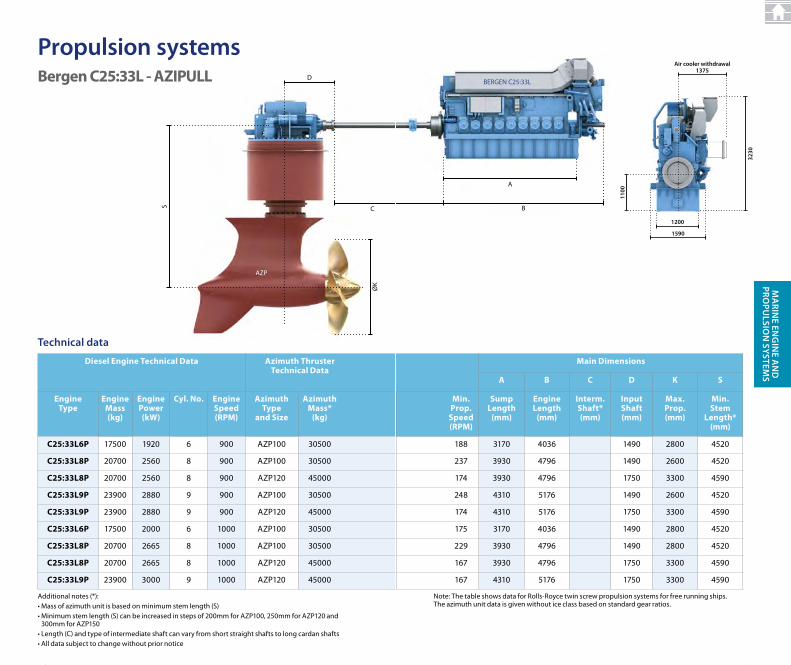
Bergen C25:33L - AZIPULL
Additional notes (*):• Mass of azimuth unit is based on minimum stem length (S)• Minimum stem length (S) can be increased in steps of 200mm for AZP100, 250mm for AZP120 and
300mm for AZP150• Length (C) and type of intermediate shaft can vary from short straight shafts to long cardan shafts• All data subject to change without prior notice
Diesel Engine technical Data Azimuth thruster technical Data
Main Dimensions
A B C D K S
Engine type
Engine Mass (kg)
Engine Power (kW)
Cyl. No. Engine Speed (RPM)
Azimuth type
and Size
Azimuth Mass*
(kg)
Min. Prop.
Speed (RPM)
Sump Length
(mm)
Engine Length
(mm)
Interm. Shaft*(mm)
Input Shaft (mm)
Max. Prop. (mm)
Min.Stem
Length* (mm)
C25:33L6P 17500 1920 6 900 AZP100 30500 188 3170 4036 1490 2800 4520
C25:33L8P 20700 2560 8 900 AZP100 30500 237 3930 4796 1490 2600 4520
C25:33L8P 20700 2560 8 900 AZP120 45000 174 3930 4796 1750 3300 4590
C25:33L9P 23900 2880 9 900 AZP100 30500 248 4310 5176 1490 2600 4520
C25:33L9P 23900 2880 9 900 AZP120 45000 174 4310 5176 1750 3300 4590
C25:33L6P 17500 2000 6 1000 AZP100 30500 175 3170 4036 1490 2800 4520
C25:33L8P 20700 2665 8 1000 AZP100 30500 229 3930 4796 1490 2800 4520
C25:33L8P 20700 2665 8 1000 AZP120 45000 167 3930 4796 1750 3300 4590
C25:33L9P 23900 3000 9 1000 AZP120 45000 167 4310 5176 1750 3300 4590
Technical data
propulsion systems
4646
B
A
BERGEN C25:33L
3230
1100
1200
1590
air cooler withdrawal1375
Note: the table shows data for rolls-royce twin screw propulsion systems for free running ships. The azimuth unit data is given without ice class based on standard gear ratios.
Diesel Engine technical Data Azimuth thruster technical Data
Main Dimensions
A B C D K S
Engine type
Engine Mass (kg)
Engine Power (kW)
Cyl. No. Engine Speed (RPM)
Azimuth type
and Size
Azimuth Mass*
(kg)
Min. Prop.
Speed (RPM)
Sump Length
(mm)
Engine Length
(mm)
Interm. Shaft*(mm)
Input Shaft (mm)
Max. Prop. (mm)
Min.Stem
Length* (mm)
C25:33L6P 17500 1920 6 900 AZP100 30500 188 3170 4036 1490 2800 4520
C25:33L8P 20700 2560 8 900 AZP100 30500 237 3930 4796 1490 2600 4520
C25:33L8P 20700 2560 8 900 AZP120 45000 174 3930 4796 1750 3300 4590
C25:33L9P 23900 2880 9 900 AZP100 30500 248 4310 5176 1490 2600 4520
C25:33L9P 23900 2880 9 900 AZP120 45000 174 4310 5176 1750 3300 4590
C25:33L6P 17500 2000 6 1000 AZP100 30500 175 3170 4036 1490 2800 4520
C25:33L8P 20700 2665 8 1000 AZP100 30500 229 3930 4796 1490 2800 4520
C25:33L8P 20700 2665 8 1000 AZP120 45000 167 3930 4796 1750 3300 4590
C25:33L9P 23900 3000 9 1000 AZP120 45000 167 4310 5176 1750 3300 4590
47
Ma
rine en
gin
e an
D
prOpu
LSiOn
SySTeMS
S
ØK
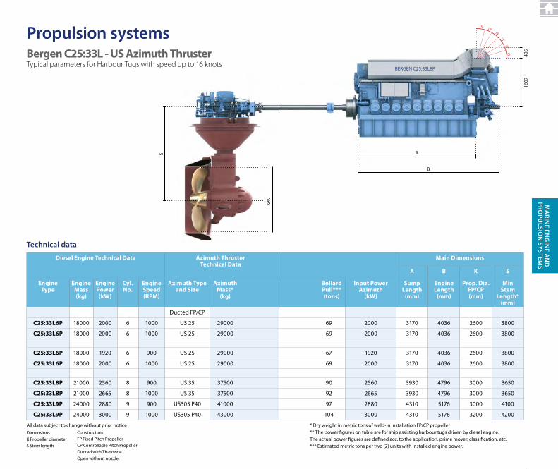
Bergen C25:33L - US Azimuth thruster
propulsion systems
Typical parameters for Harbour Tugs with speed up to 16 knots
Diesel Engine technical Data Azimuth thruster technical Data
Main Dimensions
A B K S
Engine type
Engine Mass (kg)
Engine Power (kW)
Cyl. No.
Engine Speed (RPM)
Azimuth type and Size
Azimuth Mass*
(kg)
Bollard Pull***(tons)
Input PowerAzimuth
(kW)
Sump Length
(mm)
Engine Length
(mm)
Prop. Dia. FP/CP (mm)
MinStem
Length* (mm)
ducted FP/cP
C25:33L6P 18000 2000 6 1000 uS 25 29000 69 2000 3170 4036 2600 3800
C25:33L6P 18000 2000 6 1000 uS 25 29000 69 2000 3170 4036 2600 3800
C25:33L6P 18000 1920 6 900 uS 25 29000 67 1920 3170 4036 2600 3800
C25:33L6P 18000 2000 6 1000 uS 25 29000 69 2000 3170 4036 2600 3800
C25:33L8P 21000 2560 8 900 uS 35 37500 90 2560 3930 4796 3000 3650
C25:33L8P 21000 2665 8 1000 uS 35 37500 92 2665 3930 4796 3000 3650
C25:33L9P 24000 2880 9 900 uS305 P40 41000 97 2880 4310 5176 3000 4100
C25:33L9P 24000 3000 9 1000 uS305 P40 43000 104 3000 4310 5176 3200 4200
dimensionsK Propeller diameterS Stem length
Technical data
All data subject to change without prior noticeconstructionFP Fixed Pitch PropellercP controllable Pitch PropellerDucted with TK-nozzleOpen without nozzle.
4848
1607
40515 o
15 o
15 o
15 o
15o15o
BERGEN C25:33L8P
B
A
Bergen C25:33L - US Azimuth thruster
Diesel Engine technical Data Azimuth thruster technical Data
Main Dimensions
A B K S
Engine type
Engine Mass (kg)
Engine Power (kW)
Cyl. No.
Engine Speed (RPM)
Azimuth type and Size
Azimuth Mass*
(kg)
Bollard Pull***(tons)
Input PowerAzimuth
(kW)
Sump Length
(mm)
Engine Length
(mm)
Prop. Dia. FP/CP (mm)
MinStem
Length* (mm)
ducted FP/cP
C25:33L6P 18000 2000 6 1000 uS 25 29000 69 2000 3170 4036 2600 3800
C25:33L6P 18000 2000 6 1000 uS 25 29000 69 2000 3170 4036 2600 3800
C25:33L6P 18000 1920 6 900 uS 25 29000 67 1920 3170 4036 2600 3800
C25:33L6P 18000 2000 6 1000 uS 25 29000 69 2000 3170 4036 2600 3800
C25:33L8P 21000 2560 8 900 uS 35 37500 90 2560 3930 4796 3000 3650
C25:33L8P 21000 2665 8 1000 uS 35 37500 92 2665 3930 4796 3000 3650
C25:33L9P 24000 2880 9 900 uS305 P40 41000 97 2880 4310 5176 3000 4100
C25:33L9P 24000 3000 9 1000 uS305 P40 43000 104 3000 4310 5176 3200 4200
* dry weight in metric tons of weld-in installation FP/cP propeller** the power figures on table are for ship assisting harbour tugs driven by diesel engine. the actual power figures are defined acc. to the application, prime mover, classification, etc.*** Estimated metric tons per two (2) units with installed engine power.
49
Ma
rine en
gin
e an
D
prOpu
LSiOn
SySTeMS
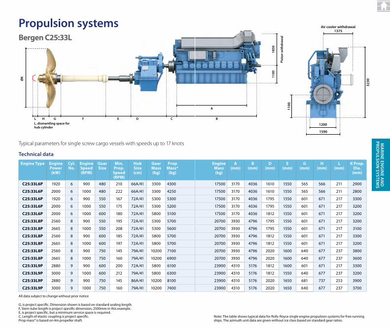
Engine type Engine Power (kW)
Cyl. No.
Engine Speed (RPM)
Gear Size
Min. Prop.
Speed(RPM)
Hub Size(cm)
Gear Mass(kg)
Prop Mass*
(kg)
Engine Mass(kg)
A(mm)
B(mm)
D(mm)
E(mm)
G(mm)
H(mm)
L(mm)
K Prop. Dia.
(mm)
C25:33L6P 1920 6 900 480 210 66A/41 3300 4300 17500 3170 4036 1610 1550 565 566 211 2900
C25:33L6P 2000 6 1000 480 222 66A/41 3300 4250 17500 3170 4036 1610 1550 565 566 211 2800
C25:33L6P 1920 6 900 550 167 72A/41 5300 5300 17500 3170 4036 1795 1550 601 671 217 3300
C25:33L6P 2000 6 1000 550 175 72A/41 5300 5200 17500 3170 4036 1795 1550 601 671 217 3200
C25:33L6P 2000 6 1000 600 180 72A/41 5800 5100 17500 3170 4036 1812 1550 601 671 217 3200
C25:33L8P 2560 8 900 550 195 72A/41 5300 5700 20700 3930 4796 1795 1550 601 671 217 3200
C25:33L8P 2665 8 1000 550 208 72A/41 5300 5600 20700 3930 4796 1795 1550 601 671 217 3100
C25:33L8P 2560 8 900 600 185 72A/41 5800 5700 20700 3930 4796 1812 1550 601 671 217 3300
C25:33L8P 2665 8 1000 600 197 72A/41 5800 5700 20700 3930 4796 1812 1550 601 671 217 3200
C25:33L8P 2560 8 900 750 145 79A/41 10200 7100 20700 3930 4796 2020 1600 640 677 237 3800
C25:33L8P 2665 8 1000 750 160 79A/41 10200 6900 20700 3930 4796 2020 1600 640 677 237 3600
C25:33L9P 2880 9 900 600 200 72A/41 5800 6100 23900 4310 5176 1812 1600 601 671 217 3300
C25:33L9P 3000 9 1000 600 212 79A/41 5800 6300 23900 4310 5176 1812 1550 640 677 237 3200
C25:33L9P 2880 9 900 750 145 86A/41 10200 8100 23900 4310 5176 2020 1650 681 737 253 3900
C25:33L9P 3000 9 1000 750 160 79A/41 10200 7400 23900 4310 5176 2020 1650 640 677 237 3700
Technical data
G, is project specific. dimension shown is based on standard sealing length.F, Stern tube length is project specific dimension, 2500mm in this example.E, is project specific, but a minimum service space is required.C, Length of elastic coupling is project specific.Prop mass* is based on 4m propeller shaft.
Typical parameters for single screw cargo vessels with speeds up to 17 knots
All data subject to change without prior notice
CghL e DF
ØK
L, dismantling space for hub cylinder
Bergen C25:33L
propulsion systems
5050
3230
1100
1200
1590
air cooler withdrawal1375
Engine type Engine Power (kW)
Cyl. No.
Engine Speed (RPM)
Gear Size
Min. Prop.
Speed(RPM)
Hub Size(cm)
Gear Mass(kg)
Prop Mass*
(kg)
Engine Mass(kg)
A(mm)
B(mm)
D(mm)
E(mm)
G(mm)
H(mm)
L(mm)
K Prop. Dia.
(mm)
C25:33L6P 1920 6 900 480 210 66A/41 3300 4300 17500 3170 4036 1610 1550 565 566 211 2900
C25:33L6P 2000 6 1000 480 222 66A/41 3300 4250 17500 3170 4036 1610 1550 565 566 211 2800
C25:33L6P 1920 6 900 550 167 72A/41 5300 5300 17500 3170 4036 1795 1550 601 671 217 3300
C25:33L6P 2000 6 1000 550 175 72A/41 5300 5200 17500 3170 4036 1795 1550 601 671 217 3200
C25:33L6P 2000 6 1000 600 180 72A/41 5800 5100 17500 3170 4036 1812 1550 601 671 217 3200
C25:33L8P 2560 8 900 550 195 72A/41 5300 5700 20700 3930 4796 1795 1550 601 671 217 3200
C25:33L8P 2665 8 1000 550 208 72A/41 5300 5600 20700 3930 4796 1795 1550 601 671 217 3100
C25:33L8P 2560 8 900 600 185 72A/41 5800 5700 20700 3930 4796 1812 1550 601 671 217 3300
C25:33L8P 2665 8 1000 600 197 72A/41 5800 5700 20700 3930 4796 1812 1550 601 671 217 3200
C25:33L8P 2560 8 900 750 145 79A/41 10200 7100 20700 3930 4796 2020 1600 640 677 237 3800
C25:33L8P 2665 8 1000 750 160 79A/41 10200 6900 20700 3930 4796 2020 1600 640 677 237 3600
C25:33L9P 2880 9 900 600 200 72A/41 5800 6100 23900 4310 5176 1812 1600 601 671 217 3300
C25:33L9P 3000 9 1000 600 212 79A/41 5800 6300 23900 4310 5176 1812 1550 640 677 237 3200
C25:33L9P 2880 9 900 750 145 86A/41 10200 8100 23900 4310 5176 2020 1650 681 737 253 3900
C25:33L9P 3000 9 1000 750 160 79A/41 10200 7400 23900 4310 5176 2020 1650 640 677 237 3700
Note: the table shows typical data for rolls-royce single engine propulsion systems for free running ships. The azimuth unit data are given without ice class based on standard gear ratios.
1850
pist
on w
ithdr
awal
1100
B
a
Bergen C25:33L
51
Ma
rine en
gin
e an
D
prOpu
LSiOn
SySTeMS
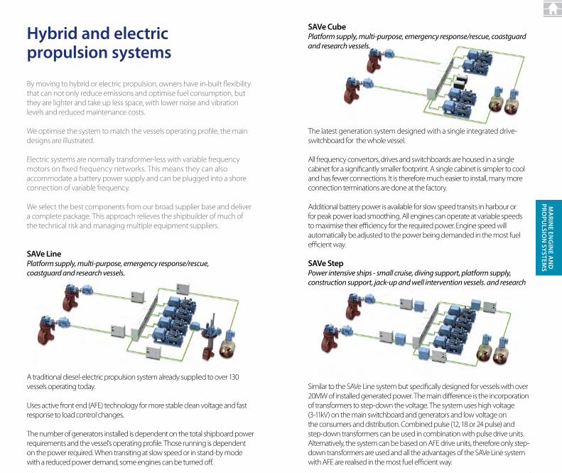
hybrid and electric propulsion systems
By moving to hybrid or electric propulsion, owners have in-built flexibility that can not only reduce emissions and optimise fuel consumption, but they are lighter and take up less space, with lower noise and vibration levels and reduced maintenance costs.
We optimise the system to match the vessels operating profile, the main designs are illustrated.
Electric systems are normally transformer-less with variable frequency motors on fixed frequency networks. This means they can also accommodate a battery power supply and can be plugged into a shore connection of variable frequency.
We select the best components from our broad supplier base and deliver a complete package. This approach relieves the shipbuilder of much of the technical risk and managing multiple equipment suppliers.
SaVe LinePlatform supply, multi-purpose, emergency response/rescue, coastguard and research vessels.
A traditional diesel-electric propulsion system already supplied to over 130 vessels operating today.
Uses active front end (AFE) technology for more stable clean voltage and fast response to load control changes.
The number of generators installed is dependent on the total shipboard power requirements and the vessel's operating profile. Those running is dependent on the power required. When transiting at slow speed or in stand-by mode with a reduced power demand, some engines can be turned off.
5252
SaVe CubePlatform supply, multi-purpose, emergency response/rescue, coastguard and research vessels.
SaVe StepPower intensive ships - small cruise, diving support, platform supply, construction support, jack-up and well intervention vessels. and research
The latest generation system designed with a single integrated drive-switchboard for the whole vessel.
All frequency convertors, drives and switchboards are housed in a single cabinet for a significantly smaller footprint. A single cabinet is simpler to cool and has fewer connections. It is therefore much easier to install, many more connection terminations are done at the factory.
Additional battery power is available for slow speed transits in harbour or for peak power load smoothing. All engines can operate at variable speeds to maximise their efficiency for the required power. Engine speed will automatically be adjusted to the power being demanded in the most fuel efficient way.
Similar to the SAVe Line system but specifically designed for vessels with over 20MW of installed generated power. The main difference is the incorporation of transformers to step-down the voltage. The system uses high voltage (3-11kV) on the main switchboard and generators and low voltage on the consumers and distribution. Combined pulse (12, 18 or 24 pulse) and step-down transformers can be used in combination with pulse drive units. Alternatively, the system can be based on AFE drive units, therefore only step-down transformers are used and all the advantages of the SAVe Line system with AFE are realised in the most fuel efficient way.
53
Ma
rine en
gin
e an
D
prOpu
LSiOn
SySTeMS
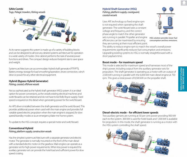
SaVe CombiTugs, Pelagic trawlers, fishing vessels
hybrid (Bypass hybrid generator)Fishing, coastal, offshore vessels
Not as sophisticated as the hybrid shaft generator (HSG) system. It is an ideal option for power conversions, as the vessels existing electrical machines and switchboards can be retained and do not have to be Rolls-Royce supply. Fixed speed is required on the diesel when generating power for the switchboard.
An AFE drive is installed between the shaft-generator and the switchboard. This provides additional power when used with the main engine and provides full variable speed electric propulsion when the main engine is stopped, for slow speed/standby modes or as an emergency/take-me-home system.
To update to the HSG concept, requires a special motor and switchboard.
Conventional hybridFishing, platform supply, construction vessels
Has the simplest systems architecture with a separate generator and electric motor. The generator is normally mounted on the front of the main diesel with a standard electric motor on the gearbox. Main engine can operate as a generator set for high power requirements. When less power is required the auxiliary generator set can provide the hotel load and sufficient power for slow speed cruising.
As its name suggests this system is made up of a variety of building blocks and can be designed to almost any desired systems architecture for operation in a wide variety of modes. One cabinet performs the task of several power functions and drives. The compact design reduces footprint size to save space and weight.
Systems architecture can accommodate: Hybrid shaft generator (PTP/PTI), Battery energy storage for load smoothing/operation, shore connection, winch drive or power for any other electrical equipment.
5454
hybrid Shaft generator (hSg) Fishing, platform supply, coastguard, coastal vessels
Uses AFE technology so fixed engine rpm is not required when operating the shaft generator. The switchboard sees a constant voltage and frequency, and the correct phase angle to match the other generator sets running in parallel. Propeller and engine efficiencies can be maximised by ensuring they are running at their most efficient point. The ability to reduce engine rpm to match the vessel's overall power requirements significantly reduces fuel consumption and emissions.Upgrading existing systems to HSG is normally straightforward with a short payback time.
Boost mode – for maximum speed This mode is selected for maximum speed and harnesses most of the ship’s power, including output from the auxiliary generator sets for propulsion. The shaft generator is operating as a motor with an output of 2,500 kW running in parallel with the 6,000 kW main diesel engine at 750 rpm. This gives a total power of 8,500 kW on the propeller shaft.
HSG solution provides lower fuel consumption and less emissions.
D esel / gas eng ne
GG
AC
DC
HSG
drv
e
DCAC Reduction gear
M
SG
Diesel-electric mode – for efficient lower speedsTwo auxiliary gensets are running at 50 per cent power providing 900 kW each to the system. 300 kW is used for hotel loads and 1,500 kW is available for propulsion. In this mode, the shaft generator is running as a motor with the HSG system controlling the shaft speed.
55
Ma
rine en
gin
e an
D
prOpu
LSiOn
SySTeMS
parallel mode – for excess power This is a new efficient way of running two engines, where the power required for propulsion and hotel loads exceeds that available from the generator sets alone. The shaft generator is feeding 500 kW into the eletrical system in parallel with one auxiliary generator. The HSG system keeps the frequency fixed at 60 HZ even if the main engine is running at around half power with variable speed.
Transit mode – for optimum efficiency This mode is used to optimise propeller efficiency for the required speed. The main engine runs at variable speed with the shaft generator supplying the ship’s electrical needs. Therefore, both auxiliary generators can be shut off.
Shore connection mode – for lower fuel consumption When the ship is in harbour it has the possibility for connecting to the normal shore power and frequency (50Hz). The HSG converts the frequency to the ship power system which is 60 Hz. It can also avoid “black-out” during changeover from shore to ship power. There is no need to run any of the auxiliary gensets, which will save fuel and reduce emissions. In addition, noise and vibration levels onboard are reduced to a minimum.
5656
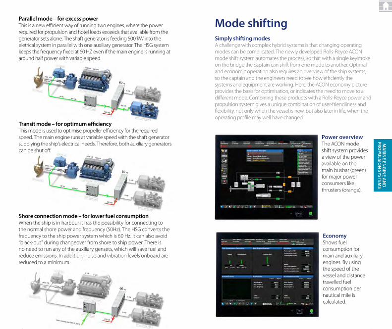
Mode shiftingSimply shifting modesA challenge with complex hybrid systems is that changing operating modes can be complicated. The newly developed Rolls-Royce ACON mode shift system automates the process, so that with a single keystroke on the bridge the captain can shift from one mode to another. Optimal and economic operation also requires an overview of the ship systems, so the captain and the engineers need to see how efficiently the systems and equipment are working. Here, the ACON economy picture provides the basis for optimisation, or indicates the need to move to a different mode. Combining these products with a Rolls-Royce power and propulsion system gives a unique combination of user-friendliness and flexibility, not only when the vessel is new, but also later in life, when the operating profile may well have changed.
power overviewThe ACON mode shift system provides a view of the power available on the main busbar (green) for major power consumers like thrusters (orange).
economyShows fuel consumption for main and auxiliary engines. By using the speed of the vessel and distance travelled fuel consumption per nautical mile is calculated.
57
Ma
rine en
gin
e an
D
prOpu
LSiOn
SySTeMS