Embed Size (px)
DESCRIPTION
The chapter covers basics of Pressure measurement techniques and instruments.
Citation preview

Experimental Gas/Aerodynamics Prof. Job Kurian
Chapter-5
Dept. of Aerospace Engg., Indian Institute of Technology, Madras 1
Module 5 Lectures 23 to 29
Measurement of Pressure
Keywords: Manometers, Elastic Pressure Sensors, Pressure Transducers, Vacuum
gauges, Pressure sensitive paints , Static and stagnation Pressures, Pitot Tubes, Prandtl
Tubes, Transmission lag.
Topics
5.0 Introduction
5.1 Units of pressure
5.2 Pressure measuring devices
5.2.1 Liquid column manometers
5.2.2 Inclined manometer
5.2.3 Mercury barometer
5.2.4 Micro manometer
5.3 Mechanical manometers
5.3.1 Bourdon tube
5.3.2 Elastic diaphrams
5.3.3 a) Corrugated diaphragms
b) Capsules, bellows
5.4 Pressure transducers
5.4.1 Diaphragm type pressure transducers
5.4.2 Piezo-electric pressure transducers
5.4.3 Pressure sensitive paints (psp)
5.5 Measurement of high pressures
5.5.1 Electrical resistance gauges – principle of operation
5.6 Ranges of different manometers
5.7 Measurement of vacuum
5.7.1 Inferential gauges

Experimental Gas/Aerodynamics Prof. Job Kurian
Chapter-5
Dept. of Aerospace Engg., Indian Institute of Technology, Madras 2
a) Mcleod gauges
b) Thermal conductivity gauges
c) Pirani gauges
d) Thermocouple gauges
e) Hot cathode ionisation gauges
f) Cold cathode ionisation gauge or penning gauge
5.8 Measurement of pressure in flows
5.8.1 Measurement of static pressure
5.8.2 Static pressure probes for subsonic flow
5.8.3 Static pressure probes for supersonic flow
5.9 Measurement of stagnation or total pressure
5.9.1 In subsonic flows
5.9.2 In supersonic flows
5.10 Lag in manometric systems

Experimental Gas/Aerodynamics Prof. Job Kurian
Chapter-5
Dept. of Aerospace Engg., Indian Institute of Technology, Madras 3
5.0 Introduction
Pressure measurement is important in many fluid mechanics related applications. From
appropriate pressure measurements velocity, aerodynamic forces and moments can be
determined. Pressure is measured by the force acting on unit area. Measuring devices usually
indicate differential pressure i.e. in relation with atmospheric pressure. This is called gauge
pressure. The measured pressure may be positive or negative with reference to the atmospheric
pressure .A negative gauge pressure is referred to as vacuum.
Fig.5.1 Explanation of the pressure terminology

Experimental Gas/Aerodynamics Prof. Job Kurian
Chapter-5
Dept. of Aerospace Engg., Indian Institute of Technology, Madras 4
5.1 Units of pressure
1Pascal(1N/m2) = 10dyne/cm
2
1mmHg = 133.32pascals
= 13.595mm Water
Standard atmosphere = 1.013 * 105N/m
2
1 millibar = 1000 dyn/cm2
1 micron = 10-6
mHg
1 torr = 1 mmHg
= 1000micron
Absolute pressure
Absolute pressure is determined as algebraic sum of the readings of a barometer and of a
manometer showing the gauge pressure. Manometers which measure absolute pressure are also
available. They measure the pressure with reference to absolute zero pressure.
5.2 Pressure measuring devices
Main characteristics of manometers are pressure range, accuracy, sensitivity and speed of
response. Pressure range of manometers varies from almost perfect vacuum to several
hundreds of atmosphere. The conventional instruments used for pressure measurement are
divided into the following groups.
1) Liquid column manometers
2) Pressure gauges with elastic sensing elements
3) Pressure transducers
4) Manometers for low absolute pressures
5) Manometers for very high absolute pressures

Experimental Gas/Aerodynamics Prof. Job Kurian
Chapter-5
Dept. of Aerospace Engg., Indian Institute of Technology, Madras 5
5.2.1 Liquid column manometers
Fig. 5.2 Liquid column manometer
For amplifying the deflection in a liquid column manometer, liquids with lower density could
be used or one of the limbs of the manometer may be inclined. Commonly used manometric
liquids are mercury, water or alcohol. Some of the important and desirable properties of the
manometric liquids are:
High chemical stability
Low viscosity
Low capillary constant
Low coefficient of thermal expansion
Low volatility
Low vapour pressure
Experimental Gas/Aerodynamics Prof. Job Kurian
Chapter-5
Dept. of Aerospace Engg., Indian Institute of Technology, Madras 6
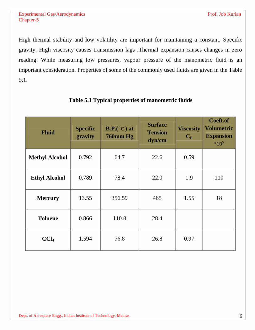
High thermal stability and low volatility are important for maintaining a constant. Specific
gravity. High viscosity causes transmission lags .Thermal expansion causes changes in zero
reading. While measuring low pressures, vapour pressure of the manometric fluid is an
important consideration. Properties of some of the commonly used fluids are given in the Table
5.1.
Table 5.1 Typical properties of manometric fluids
Fluid Specific
gravity
B.P.( oC ) at
760mm Hg
Surface
Tension
dyn/cm
Viscosity
CP
Coeft.of
Volumetric
Expansion 5*10
Methyl Alcohol 0.792 64.7 22.6 0.59
Ethyl Alcohol 0.789 78.4 22.0 1.9 110
Mercury 13.55 356.59 465 1.55 18
Toluene 0.866 110.8 28.4
CCl4 1.594 76.8 26.8 0.97
Experimental Gas/Aerodynamics Prof. Job Kurian
Chapter-5
Dept. of Aerospace Engg., Indian Institute of Technology, Madras 7
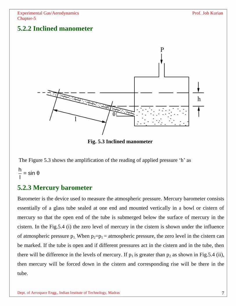
5.2.2 Inclined manometer
Fig. 5.3 Inclined manometer
The Figure 5.3 shows the amplification of the reading of applied pressure „h‟ as
h= sin θ
l
5.2.3 Mercury barometer
Barometer is the device used to measure the atmospheric pressure. Mercury barometer consists
essentially of a glass tube sealed at one end and mounted vertically in a bowl or cistern of
mercury so that the open end of the tube is submerged below the surface of mercury in the
cistern. In the Fig.5.4 (i) the zero level of mercury in the cistern is shown under the influence
of atmospheric pressure p1. When p2=p1 = atmospheric pressure, the zero level in the cistern can
be marked. If the tube is open and if different pressures act in the cistern and in the tube, then
there will be difference in the levels of mercury. If p1 is greater than p2 as shown in Fig.5.4 (ii),
then mercury will be forced down in the cistern and corresponding rise will be there in the
tube.

Experimental Gas/Aerodynamics Prof. Job Kurian
Chapter-5
Dept. of Aerospace Engg., Indian Institute of Technology, Madras 8
(i) (ii) (iii)
Fig. 5.4 Principle of mercury barometer
The balance of pressures will be given by p1 = p2 + Hρ ……………………………… 5.1
(where H is the difference between levels of mercury in the cistern and in the tube and ρ the
density of mercury). From the Figure 5.4 (ii), H=h+d
The quantity of mercury that has left the cistern is same as that has risen in the tube.
1 2A d = A h where A1 and A2 are areas of the cistern and the tube respectively.
2
1
Ad = h
A
H = 2
1
Ah+h
A
=
2
1
Ah 1+
A………………………..5.2
Replacing H in equation 5.1
21 2
1
Ap = p +h 1+ ρ
A
…………………………..5.3
p2 0 in practical cases as the tube will be evacuated and sealed.
21
1
Ap = h 1+ ρ
A ………………………..5.4

Experimental Gas/Aerodynamics Prof. Job Kurian
Chapter-5
Dept. of Aerospace Engg., Indian Institute of Technology, Madras 9
5.2.4 Micromanometer
For accurate measurement of extremely small pressure differences micromanometers are used
.In the Figure 5.5 the instrument is initially adjusted such that p1 = p2 .
Fig. 5.5 Typical Micromanometer
The meniscus in the inclined tube is located at a reference level fixed by the hairline viewed
through the magnifier. The reading of the micrometer is noted. Application of the unknown
pressure difference causes the meniscus to move off the hairline but it can be restored to the
initial position by raising or lowering the well (mercury sump) The difference in the initial and
final micrometer readings gives the height of the mercury column and hence the pressure.
Pressures as low as 0.025mm water column can be measured.

Experimental Gas/Aerodynamics Prof. Job Kurian
Chapter-5
Dept. of Aerospace Engg., Indian Institute of Technology, Madras 10
5.3 Mechanical manometers
Mechanical manometers provide faster response than liquid column manometers. In liquid
column measurements, lag is due to the displacements of the liquid. In elastic sensing element
type of manometers the time lag is due to the time required for equalisation of pressure to be
measured with that in the sensing chamber. The deformation of elastic sensing elements is
measured with the aid of kinematic, optical or electrical systems. There are three types of
elastic sensing elements which are (i) Bourdon Tubes (ii) Diaphragms (flat or corrugated) (iii)
Bellows
5.3.1 Bourdon tube
Bourdon tube is the oldest pressure sensing element .It is a length of metal tube of elliptical
cross section and shaped into letter „C‟.
Fig.5.6 Bourdon tube pressure gauge

Experimental Gas/Aerodynamics Prof. Job Kurian
Chapter-5
Dept. of Aerospace Engg., Indian Institute of Technology, Madras 11
One end is left free and the other end is fixed and is open for the pressure source to be applied.
A tube of elliptical cross section has a smaller volume than a circular one of the same length
and perimeter. When connected to the pressure source it is made to accommodate more of the
fluid. Resultant of all reactions will produce maximum displacement at the free end. Within
close limits, the change in angle subtended at the centre by a tube is proportional to the change
of internal pressure and within the limits of proportionality of the material; the displacement of
the free end is proportional to the applied pressure.
The ratio between major and minor axes decides the sensitivity of the Bourdon tube. The
larger is the higher is the sensitivity. Materials of the Bourdon tube is Phosphor bronze,
Beryllium bronze or Beryllium Copper.
5.3.2 Elastic diaphragms
The pressure sensors making use of elastic diaphragms consist of a diaphragm fixed in a
tubular member. The pressure to be measured is applied on one side. The mathematical relation
between pressure and central deflection for a flat circular diaphragm is given by
34
c c
4 2
16Et y yp = +0.488 +....
t t3a 1-μ
……………………….. 5.5
To have a linear pressure deflection relation, the second and later terms should be small.
p = applied pressure
t = thickness
a = radius
yc = central deflection
E = Youngs modulus
μ = Poisson‟s ratio lateral strain
Axial strain

Experimental Gas/Aerodynamics Prof. Job Kurian
Chapter-5
Dept. of Aerospace Engg., Indian Institute of Technology, Madras 12
Fig.5.7 Diaphragm pressure gauge
As seen from the equation the pressure deflection relation is not linear. If a non-linearity of 5%
is acceptable the deflection must be less than 1/3 of thickness. Neglecting the higher order
terms within brackets,
4
C
4 2
16Et yp = ×
t3a π 1-μ
3
C
4 2
16 Et yp =
3a 1-μ
CCyy
=p
4 2
3
C
3a 1-μ
16Et y …………………… 5.6
2 4
C
3
3 1-μ ay=K =
p 16E t ………………… 5.7
where „K‟ is the sensitivity of the device.

Experimental Gas/Aerodynamics Prof. Job Kurian
Chapter-5
Dept. of Aerospace Engg., Indian Institute of Technology, Madras 13
The natural frequency of the diaphragm may be written as follows:
d
1/2
22
E tω = 10.2 rad/s
a12ρ 1-μ
……………… 5.8
Diaphragm has infinite number of natural frequencies and the lowest of them is considered
here. From the two equations for sensitivity „K‟ and the natural frequencyω .
Sensitivity (K) and natural frequency (ω ) are related by
KC
2
d
y 1.63= =
p ω tρ …………………….. (5.9)
( dρ is density of diaphragm material)
Sensitivity is inversely proportional to square of natural frequency. Sensitivity can be improved
by lowering the natural frequency. The natural frequency should be 3 to 4 times the frequency
of pressure pulsations. Compared to bourdon tubes diaphragms have higher natural
frequencies. Hence, they can be used for the measurement of dynamic pressures of higher
frequency fluctuations. They can be installed flush with the surface of the body and hence there
is only much less transmission lag.
5.3.3 a) Corrugated diaphragms
Corrugated diaphragms permit considerably larger deflections than flat diaphragms. Their
number and depth control the response and sensitivity. The greater the number and depth, the
more linear is its deflection and greater is the sensitivity.

Experimental Gas/Aerodynamics Prof. Job Kurian
Chapter-5
Dept. of Aerospace Engg., Indian Institute of Technology, Madras 14
Fig. 5.8 Corrugated diaphragm
5.3.3 (b) Capsules, Bellows
For even larger deflections than the diaphragms corrugated diaphragms are made in to boxes or
bellows. Bellows are most commonly used to measure small steady pressures.
5.4 Pressure Transducers
5.4.1 Diaphragm type pressure transducers
They convert the pressure to be measured into electrical signals. For example, pressure
transducers whose operating principle is based on measuring changes in inductive, capacitive
or ohmic resistances caused by the deformation of an elastic element.
Capacitance C = a a/ d ………………….5.10
where a absolute permittivity
a
9
0
1= K
4π×9×10 E/m
a = area of plates
d = distance between the plates

Experimental Gas/Aerodynamics Prof. Job Kurian
Chapter-5
Dept. of Aerospace Engg., Indian Institute of Technology, Madras 15
Fig.5.9 Elastic diaphragm used in a
parallel plate capacitor
With the application of pressure, the diaphragm deforms with the central deflection as shown.
This changes the capacitance in an electrical circuit which can be calibrated against pressure to
be measured.
5.4.2 Piezo-Electric pressure transducers
The word piezo-electric is derived from the Greek word “piezein” meaning squeeze or press.
Certain materials possess the ability to generate electrical potential when subjected to
mechanical strain. Conversely, they change dimensions when supplied with voltage. The
potential developed by application of stress is not held under static conditions. Dynamic
pressures in the range of frequencies from kHz to 100MHz can be measured using piezo-
electric transducers. The use of piezo-electric effect is limited to dynamic measurements. Some
materials exhibiting piezo electric properties are quartz, tourmaline, barium titanate, and Lead
zirconate. Quartz is the preferred material, as it possesses good mechanical properties. Also, it
is a good insulator least influenced by moisture.

Experimental Gas/Aerodynamics Prof. Job Kurian
Chapter-5
Dept. of Aerospace Engg., Indian Institute of Technology, Madras 16
5.4.3 Pressure Sensitive Paints (PSP)
They are composed of luminescent molecules dispersed in Oxygen permeable polymer binder.
When PSP is exposed to blue or an ultraviolet light the luminescent molecules are excited to a
higher energy level.
From this excited state they can discharge in three ways:
(i) by discharging light
(ii) by transferring energy to the polymer binder(heating)
(iii) colliding with Oxygen molecules.
Since the luminescent molecules react with Oxygen they collide and release light at the same
time. The amount of light emitted is inversely proportional to the amount of Oxygen molecules
on the surface.
5.5 Measurement of high pressures
5.5.1 Electrical resistance gauges – principle of operation
Bourdon Tube or strain gauge can be used for high pressures. Very high pressures (say above
1000bars) may be measured by means of electrical resistance gauges which are known as
Bridgeman gauge. By way of principle of operation, they make use of resistance change
brought about by direct application of pressure to the conductor itself. Referring to the Figure,
the sensing element is the thin wire of Magnanin (84 Cu + 12 Mn + 4 Ni) or an alloy of Gold
and Chromium (2.1%) which is loosely wound. When pressure is applied, bulk compression
effects produce a change in resistance which may be calibrated against pressure. The general
relation between electrical and mechanical may be derived as follows:

Experimental Gas/Aerodynamics Prof. Job Kurian
Chapter-5
Dept. of Aerospace Engg., Indian Institute of Technology, Madras 17
Fig.5.10 Sensor of a Bridgemans Gauge
2
ρL ρLR = =
A CD …………………………………………………………..(5.11)
R = Resistance, ohms
L = Length of conductors
A = Area = CD2
where D is the diameter of the circular conductor and C a constant
ρ= Resistivity ohm cm
If the conductor is strained each of the quantities in the equation will change.
Differentiating
2
22
CD Ldρ+ρdL -2CρDLdDdR =
CD
2
1 dD= Ldρ+ρdL -2ρL
CD D
……………. 5.12
Dividing (5.12) by (5.11) gives
dR dL 2dD dρ
= - +R L D ρ

Experimental Gas/Aerodynamics Prof. Job Kurian
Chapter-5
Dept. of Aerospace Engg., Indian Institute of Technology, Madras 18
The wire will be subjected to biaxial stresses because the ends in providing electrical
continuity will not be subjected to pressure.
Fig.5.11 Bi-axial stresses on a small element
Let us consider a general element subjected to stresses which may be denoted as xσ and yσ .
Suppose xσ and yσ are applied one at a time. If xσ is applied first, there will be strain in the
x – direction = xσ
E
Because of Poisson‟s effect, the strain in y direction = σ
-μE
If yσ is applied first
Strain in y direction = yσ
E
Strain in x direction = - yσμ
E
There will be a net strain of
x x y
1= σ -μσ
E
y x
1= - σy-μσ
E
Stresses are nothing but applied pressure
x yσ = σ = -p assuming Zσ = 0
Lateral Strain
x y
dD p= = = - 1-μ
D E

Experimental Gas/Aerodynamics Prof. Job Kurian
Chapter-5
Dept. of Aerospace Engg., Indian Institute of Technology, Madras 19
Z
dL p= = 2μ
L E
Biaxial stress situation is assumed.
Longitudinal Strain
dR dL 2dD dρ
= - +R L D ρ
(Substitute from above)
= p p dρ
2μ +2 1-μ +E E ρ
2p dρ
= +E ρ
If specific resistance ρ does not depend on pressure dρ
ρcan be neglected.
dR p= 2
R E
R = R0 (1 + bp) where, b = 2 / E.
dR/R 2 dρ/ρ
= +p E p
………………………5.13
where b is called pressure coefficient of resistance. Resistance varies linearly with pressure.
5.6 Ranges of different manometers
5.7 Measurement of vacuum
Pressures below atmosphere is vacuum. Very low pressures may be defined as below 1mmHg.
Ultra low pressures is less than a milli micron (<10-3
micron )
Liquid column manometers 10 – 0.5 x 10⁶pascals
Bourdon tubes Vacuum to a few thousand bars
Diaphragms Vacuum to a few hundred bars
Bellows Vacuum to a hundred bar
Experimental Gas/Aerodynamics Prof. Job Kurian
Chapter-5
Dept. of Aerospace Engg., Indian Institute of Technology, Madras 20
Measurement of vacuum may be by two methods
Direct measurement
Resulting in a displacement caused by the action of force [Spiral Bourdon tubes, flat or
corrugated diaphragm, capsules and various other manometers]
Indirect measurement or inferential methods
Pressure is determined through the measurement of certain pressure controlled properties such
as volume, thermal conductivity etc.
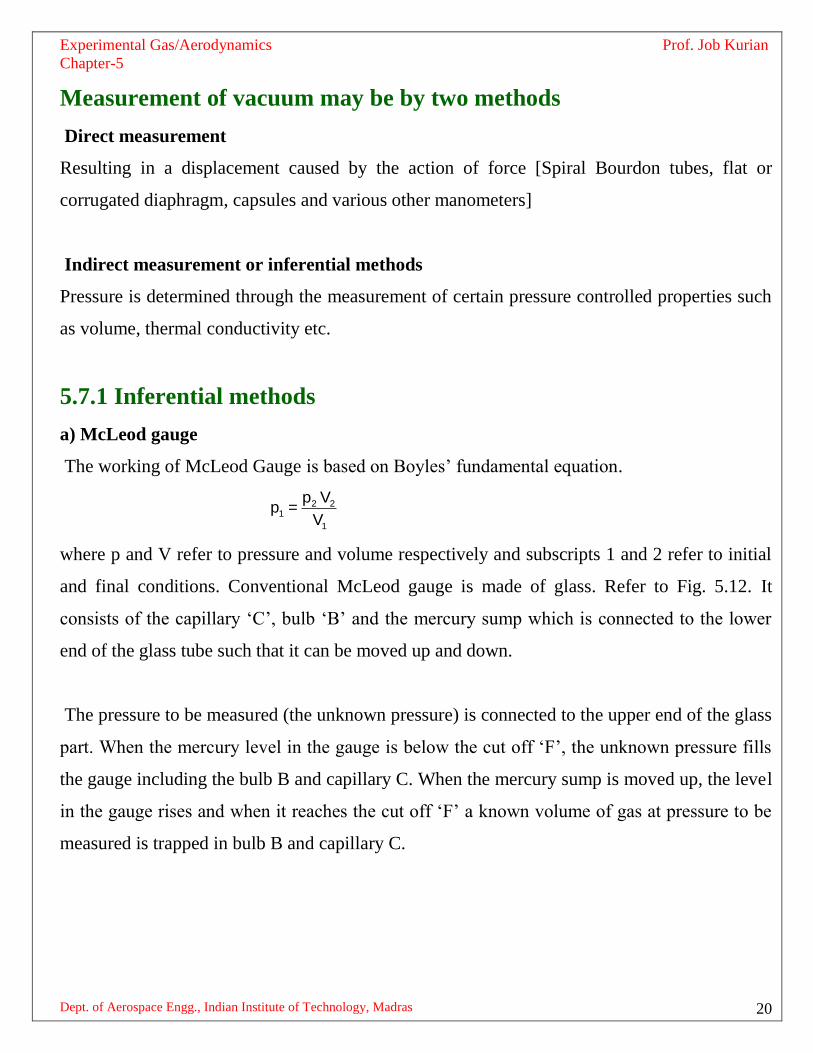
5.7.1 Inferential methods
a) McLeod gauge
The working of McLeod Gauge is based on Boyles‟ fundamental equation.
2 21
1
p Vp =
V
where p and V refer to pressure and volume respectively and subscripts 1 and 2 refer to initial
and final conditions. Conventional McLeod gauge is made of glass. Refer to Fig. 5.12. It
consists of the capillary „C‟, bulb „B‟ and the mercury sump which is connected to the lower
end of the glass tube such that it can be moved up and down.
The pressure to be measured (the unknown pressure) is connected to the upper end of the glass
part. When the mercury level in the gauge is below the cut off „F‟, the unknown pressure fills
the gauge including the bulb B and capillary C. When the mercury sump is moved up, the level
in the gauge rises and when it reaches the cut off „F‟ a known volume of gas at pressure to be
measured is trapped in bulb B and capillary C.

Experimental Gas/Aerodynamics Prof. Job Kurian
Chapter-5
Dept. of Aerospace Engg., Indian Institute of Technology, Madras 21
Fig.5.12 Mc Leod gauge

Experimental Gas/Aerodynamics Prof. Job Kurian
Chapter-5
Dept. of Aerospace Engg., Indian Institute of Technology, Madras 22
Mercury is then forced up into the bulb and capillary. Assume the sump is raised to such a
level that the gas at the pressure to be measured which filled the volume above the cut off is
now compressed to the volume represented by the column h.
Suppose the original volume after then mercury reaches F is0V . This is at a pressure being
measured p1
0 1 1
2
1
2
0 1 1
2
1 0
V p ah (p h)
p ah ah
V p p ah ah
p (V ah) ah
As „ah‟ is <<< V0 it is neglected.
0
2
1
ahp
V
Applications of McLeod gauge
McLeod gauge is used mainly for calibrating other inferential type of gauges. The
shortcomings of the McLeod gauge are its fragility and the inability to measure continuously.
The vapor pressure of Mercury sets the lower limit of measurement range of the gauge.
b) Thermal conductivity gauges
The working principle of thermal conductivity gauges is that at low pressures heat lost by a
heated object by conduction through molecules will depend on pressure. This is valid only for
certain pressure range.
When the mean free path is comparable with the dimensions of the gauge head the heat loss
from a heated wire in the gauge head will be by (i) conduction through leads (ii) radiation to
surroundings (iii) conduction through molecules.

Experimental Gas/Aerodynamics Prof. Job Kurian
Chapter-5
Dept. of Aerospace Engg., Indian Institute of Technology, Madras 23
Fig.5.13 Gauge head of the thermal conductivity gauge
The range of thermal conductivity gauges is from mm of Hg to 10-3
mmHg. At higher
pressures, heat loss from the heated wire is insensitive to the pressure change. At lower
pressure heat loss by (i) and (ii) become more significant. There are two kinds of the
thermocouple gauges.
c) Pirani gauge
Measures change in resistance of the heated wire when it looses heat to the gas molecules in
the gauge head. In this case the gauge is called pirani gauge.
d) Thermocouple gauge
Instead of measuring electrical resistance, a thermocouple is kept in contact with the heated
wire and the temperature of the wire is directly measured as a measure of pressure.

Experimental Gas/Aerodynamics Prof. Job Kurian
Chapter-5
Dept. of Aerospace Engg., Indian Institute of Technology, Madras 24
Fig.5.14 Thermocouple gauge head
e) Hot cathode ionisation gauges
At higher levels of vacuum, the measurement of pressure is by using Ionisation gauges. They
operate on the principle of ionising the gas by means of electrons emitted by a heated filament.
The kinetic energy acquired by an electron in passing through a potential difference of V volts
corresponds to a value equal to V*e where e is the charge of the electron. When this energy
exceeds a certain critical value corresponding to the ionization potential Vi, there is a
possibility that collisions between molecules and electrons will result in the formation of +ve
ions. The relatively high velocity electrons on hitting a gas molecule drives an electron out of
it leaving it positively charged. For gases such as N2, O2 etc, Vi is ~ 15volts. The measurement
of the ions produced is a measure of the pressure. The electrons are speeded up by an electric
field and +ve ions produced are collected. The number of +ve ions formed will depend on the
number of molecules and therefore on the pressure.

Experimental Gas/Aerodynamics Prof. Job Kurian
Chapter-5
Dept. of Aerospace Engg., Indian Institute of Technology, Madras 25
Fig.5.15 Ionisation gauge
The gauge consists of a cathode, grid anode and a negative plate. The negative plate is at ~10V
negative with respect to the cathode. The electrons emitted by the hot cathode (filament) are
speeded up by the electric field and the positive ions produced are collected by the negative
plate.
g) Cold cathode ionisation gauge (Penning gauge)
This gauge also works on the ionization principle. Positive ions are produced by the electrons
and current due to these ions gives a measure of the pressure. Electrons are ejected from a cold
cathode of Zirconium, Thorium by electric discharge. The gauge consists of two plate cathodes
and a ring anode . A potential difference of ~2KV is applied across the electrodes.
The travel of electrons is made over a much longer distance. The secondary electrons are made
to travel in helical paths before reaching the anode. This is accomplished by a magnetic field.

Experimental Gas/Aerodynamics Prof. Job Kurian
Chapter-5
Dept. of Aerospace Engg., Indian Institute of Technology, Madras 26
Fig.5.16 Cold cathode ionization gauge
Magnetic poles are kept such that the flux with lines of force is applied perpendicular to the
two cathodes.
5.8 Measurement of pressure in flows
In flows, distinction has to be made between static and stagnation pressures.
Static pressure
Pressure acting on the surface of a body imagined to be moving with the fluid with the same
velocity as the medium is the static pressure.
Stagnation pressure
It is the pressure of a fluid imagined to be brought to rest isentropically.

Experimental Gas/Aerodynamics Prof. Job Kurian
Chapter-5
Dept. of Aerospace Engg., Indian Institute of Technology, Madras 27
5.8.1 Measurement of static pressure
Common technique is to connect a probe to an orifice drilled perpendicular to the wall of the
model where the streamlines are undistorted and parallel.
Fig.5.17 Static pressure orifice (tap) on a flat wall
Static hole diameter is about 1/5 of the boundary layer thickness. Practically the diameter is
about 0.25mm on small models and 2.5mm on larger installations. The correctness of the static
pressure measured is dependent on„d‟ the orifice diameter [Fig.5.17]. The influence of the
orifice diameter on the error in static pressure measurements is given graphically in Fig.5.18.

Experimental Gas/Aerodynamics Prof. Job Kurian
Chapter-5
Dept. of Aerospace Engg., Indian Institute of Technology, Madras 28
Fig.5.18 Influence of error on orifice diameter
The static pressure orifices (taps) on the walls of the flow channel provide the wall static
pressure. The wall static pressure can not be assumed to prevail inside the flow. In order to get
the pressure inside the flow, probes of suitable design have to be made use of.
5.8.2 Static pressure probes for subsonic flow
The commonly used static pressure probe in subsonic flows is the Prandtl probe. The Prandtl
probe is an intrusive device. The pressure sensing orifices on the periphery of the probe are
carefully located such that the influence of the nose and stem of the probe nullify each other.

Experimental Gas/Aerodynamics Prof. Job Kurian
Chapter-5
Dept. of Aerospace Engg., Indian Institute of Technology, Madras 29
Fig.5.19 The Prandtl probe
Fig.5.20 The nose and stem effects in a Prandtl tube
Because of the intrusive nature of the probe, the flow will be accelerated by the nose. The
effect will be to reduce the static pressure which is called the nose effect. In contrast, the effect
of stem will be to locally stagnate the flow and thereby to increase the static pressure. This

Experimental Gas/Aerodynamics Prof. Job Kurian
Chapter-5
Dept. of Aerospace Engg., Indian Institute of Technology, Madras 30
effect is the stem effect. As shown in the Fig.5.20, the position of the orifices are so chosen
that the two effects neutralize each other. Additionally the probe must be slender (say ~ 1.0 to
1.5mm dia) and kept parallel to the flow.
5.8.3 Static pressure probes for supersonic flow
When Mach number is more than 1.0, shock appears. When the cone angle of the probe is less
than the shock detachment angle for the given Mach number [shown in Fig.5.23] and if the
orifices are located well downstream of the shock wave, the measured static pressure will tend
towards the value for the undisturbed flow. Conical or ogival shaped tubes are used.
Probes are made small and with static taps on the cone surface. The effect of yaw is reduced by
arranging several orifices so that the pressure inside the tube is an average value. Usually the
tube has 4 to 8 orifices whose diameter is about 1/10 th of the outside diameter of the tube.
Fig.5.21 Ogival shaped static pressure probe for supersonic flow
Good results are obtained with ogival tubes. The tube shown in Fig.5.21 has a systematic error
within 1%. Angle of the cone should be less than the angle at which the shock wave becomes
detached from the cone. The error in the measurement of static pressure decreases as the
distance of the orifice from the tip of the probe increases.

Experimental Gas/Aerodynamics Prof. Job Kurian
Chapter-5
Dept. of Aerospace Engg., Indian Institute of Technology, Madras 31
Fig.5.22 Conical static pressure probe for supersonic flow
Fig.5.23 Maximum deflection angle for different
Mach numbers

Experimental Gas/Aerodynamics Prof. Job Kurian
Chapter-5
Dept. of Aerospace Engg., Indian Institute of Technology, Madras 32
Fig.5.24 Reflection of the shock from the wall
It is important to have long pointed tubes. Otherwise there is the possibility that the reflected
shock may affect the static pressure readings. Roughness at the edges of the orifices too may
cause large errors in measurement.
5.10 Measurement of stagnation or total pressure
5.9.1 Insubsonic flows
The gas particles come to rest so quickly at the stagnation point of a body, that heat transfer
and friction losses are negligible. Therefore, in subsonic flows only isentropic changes occur.
Hence the stagnation pressure measured in a subsonic flow is not significantly different from
that in the settling chamber. Total pressure is measured with a Pitot tube which a cylindrical
tube is having an orifice pointing towards the flow. Axis of tube must coincide with the flow
direction. It is a practice to use tubes which generally have blunt ends.
Such tubes are insensitive to yaw upto ±10 to 120
The relation between the stagnation pressure measured and the static pressure may be
expressed as follows:
r
r -12
0
p r -1= 1+ M
p 2
where p0 is the total pressure and p the static pressure.
Experimental Gas/Aerodynamics Prof. Job Kurian
Chapter-5
Dept. of Aerospace Engg., Indian Institute of Technology, Madras 33
5.9.2 Insupersonic velocities
Shockwave appears upstream of the tube nose. Therefore tube measures only pressure behind
the shock wave. Normal shock equations give the relation between the total pressures upstream
and downstream of the shock. As the bow shock formed in front of the Pitot tube has the
normal part only in the central region, the tube diameter for measurements in supersonic flow
is usually kept very small.
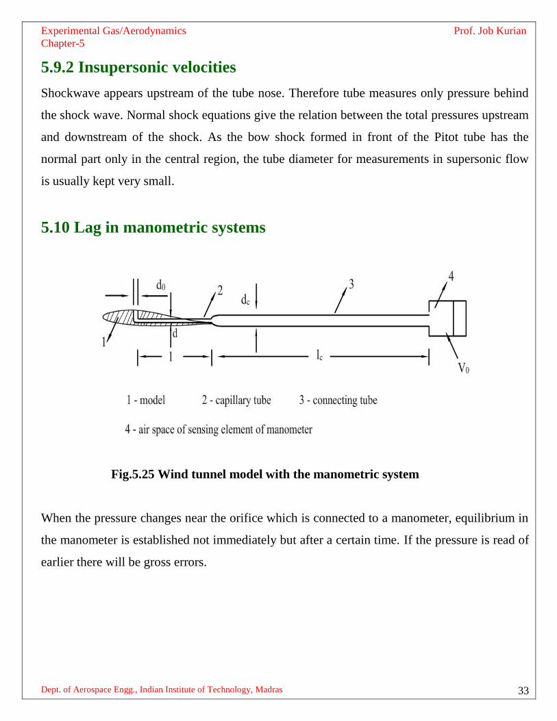
5.10 Lag in manometric systems
Fig.5.25 Wind tunnel model with the manometric system
When the pressure changes near the orifice which is connected to a manometer, equilibrium in
the manometer is established not immediately but after a certain time. If the pressure is read of
earlier there will be gross errors.

Experimental Gas/Aerodynamics Prof. Job Kurian
Chapter-5
Dept. of Aerospace Engg., Indian Institute of Technology, Madras 34
Fig.5.26 Transmission lag as a function of capillary diameter

Experimental Gas/Aerodynamics Prof. Job Kurian
Chapter-5
Dept. of Aerospace Engg., Indian Institute of Technology, Madras 35
Fig.5.cTransmission lag as a function of orifice diameter
Smaller transmission lags are necessary not only for high reliability but also for reducing the
duration of experiments. Equilibrium will be established in the manometric system later after
the pressure on the model is stabilized. The run times should be longer than the transmission
lag.
Transmission lag is caused by:
a) Resistance of the tubes
b) The change in air density
c) and inertia of the moving masses
The main factors influencing the transmission lag are the orifice diameter do, the diameter d of
the capillary and dc of the connecting tube and their respective lengths l and lc .

Experimental Gas/Aerodynamics Prof. Job Kurian
Chapter-5
Dept. of Aerospace Engg., Indian Institute of Technology, Madras 36
The orifice diameter is of small influence when d/do < 2.5. When d/do > 2.5 the transmission
lag increases sharply. The orifice diameter should not be less than half the diameter of the
capillary tube. The influence of the diameter of the capillary tube is very strong. A reduction of
this diameter has its main effect an increase in the resistance to the flow of gas. An increase in
the length of the capillary tube has a significant effect on the lag. Capillary tubes should have
larger diameter and shorter length.
*******************************************************

Experimental Gas/Aerodynamics Prof. Job Kurian
Chapter-5
Dept. of Aerospace Engg., Indian Institute of Technology, Madras 37
Exercises
Answer the following
1. Write down the relation amon the pressure units Pascal, Torr, micron and Standard
atmosphere.
2. What are the important and desirable properties of the manometric fluids?
3. How can the sensitivity of the liquid column manometer improved?
4. With the help of sketches explain the working of a mercury barometer.
5. For the given material, what decides the sensitivity of the Bourdon gauge?
6. What are the common materials used for Bourdon gauge?
7. Write down the expression relating the central deflection of the elastic diaphragm and
the applied pressure.
8. How are the natural frequency and the sensitivity of the elastic diaphragm type pressure
gauge related?
9. Why are corrugated diaphragms used in pressure gauges?
10. Explain a diaphragm pressure transducer working on capacitance principle.
11. Sketch and explain an electric resistance gauge for high pressure measurement.
12. Name a couple of artificial piezo electric crystals. What range of frequencies of dynamic
pressures they can be employed?
13. Explain a Mc Leod gauge. Mention its drawbacks.
14. Differentiate between Pirani and thermocouple gauges.
15. Explain a cold cathode ionization gauge.
16. Why are the wall static pressure holes very small?
17. Graphically show the variation of measurement error with increasing value of wall static
orifice.
18. What is understood by „stem effect‟ and „nose effect‟ in Prandtl tubes.
19. Sketch a probe marking the position of orifices for static pressure measurements in
supersonic flows.

Experimental Gas/Aerodynamics Prof. Job Kurian
Chapter-5
Dept. of Aerospace Engg., Indian Institute of Technology, Madras 38
20. Pitot tubes are used both in subsonic and supersonic flows. Is the measurement principle
different in the two cases?
Work out the following numerical problems
1. In the measurement of low pressure using a Mc Leod gauge [whose volume above cut
off is 200cc and capillary diameter 0.6mm], the level difference between the two limbs
is seen as 6mm. Find the pressure measured.
2. An experimental rocket powered aircraft is flying at a velocity of 1035m/s at an altitude
corresponding to 0.720* 105 N/m
2 and 216.6K. A pitot tube is mounted in the nose of
the aircraft. What is the pressure measured by the Pitot tube? What is the pressure
measured if the aircraft is assumed to fly at 200m/s at the same altitutde.