Embed Size (px)
Citation preview

Pressure Gauge Options
XLL PLUS! Performance • • • • XSF FlutterGuard™ • • • STD • XNP Nickel plated socket • • • XBF WaII mounting bracket • XFW Back flange • XFF Front flange • • • • • XUC U-clamp • • • • STD • XLJ Dry liquid-fillable gauge • • • • XOS Overload stop STD • STD • STD(1) • • XVS Underload stop STD • STD • STD(1) • • XTS Throttle screw • • • • • • • • XTU Throttle plug • • • • • XT4 Throttle plug • • • • XT5 Throttle plug • • • STD XT7 Throttle plug • • STD • XT9 Throttle plug • • • • XS4 Slotted link movement (decrease) • • • • XRJ Slotted link (increase) • • • • XAP Adjustable pointer STD • • • • XMP Micrometer pointer STD • STD STD • XSH Red set hand stationary • • • • • XEO Red set hand adjustable • • • • • • XEP Maximum pointer • • • • • • • XEQ Minimum pointer • • • • • XPD Plastic window • • STD • STD(1) • • STD STD STD STD STD XSG Safety glass • • • • • • XDA Dial marking • • • • • • • • • • • XNN Paper tag • • • • • • • • XNH Stainless steel tag • • • • • • • • XAB Absolute pressure • • • XAJ 1⁄2% optional accuracy STD • • • XAN 1% optional accuracy STD STD STD • XRA Retard scale • • • • • • XBD Black dial • • • • • • • • • • • • X6B Oxygen-cleaned gauges (gaseous) • • • • • • • • • • XTB Tip bleed • • XED High and low electric contacts • XEE Double high-electric contacts • XEF Double low-electric contacts • XEG Electric contacts off at low or •
high and in-between XGV Silicone-filled gauge • • • • • XGX Halocarbon-filled gauge • • • • XCH Carrying handle • XC4 Calibration Chart • • • • • • • •
TEST
GAU
GES
PROC
ESS
GAUG
ES
1009
(21 ⁄2,̋
31 ⁄2˝)
1009
(41 ⁄2,̋
6˝)
1008
S
GENE
RAL
SERV
ICE
SPEC
IAL
SERV
ICE
1490
/149
5 SE
RIES
1001
T
1005
/100
0 SE
RIES
1007
P
1008
A
CODE DESCRIPTION PRESSURE GAUGE TYPE
TEST & PROCESS GAUGES STAINLESS STEEL CASE INDUSTRIAL GAUGES COMMERCIAL GAUGES
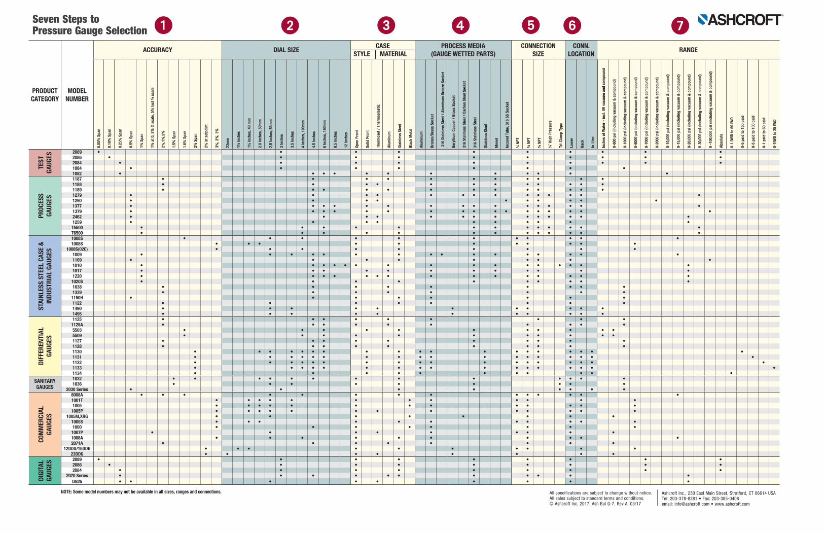
NOTES: The options listed above are only a partial listing. For other options on these or other pressure instruments please call the factory for availability. Not all variations available for each size, connection, range in a specific gauge, model/type. Minimums may also apply.
(1) Available on 40mm and 50mm.
Seven Steps to Select a Pressure Gauge
Ashcroft Inc., 250 East Main Street, Stratford, CT 06614 USATel: 203-378-8281 • Fax: 203-385-0408email: [email protected] • www.ashcroft.com
All specifications are subject to change without notice. All sales subject to standard terms and conditions. © Ashcroft Inc. 2017, Ash Bul G-7, Rev A, 03/17
4. MEDIA / WETTED PARTS The wetted parts of the pressure gauge, the Bourdon tube and socket must be compatible with the process media. If not compatible with the wetted parts of the gauge, corrosion will occur. Corrosion of gauge wetted parts will eventually cause gauge failure and possibly safety issues. When the gauge wetted parts are not compatible with the process media, a diaphragm should be considered.
7. PRESSURE RANGES ASME B40.100 recommends that normal operating pressure be confined to 25%-75% of the scale. If pulsation is present in the process, maximum operating gauge pressure should not exceed 50% of the full-scale range. CONCLUSION To properly select a pressure gauge, consider the gauge process, range, environment, accuracy, dial size, connection and mounting requirements.
3. CASE STYLE / MATERIAL Environmental considerations include ambient temperature, air-borne particulate, condensation, humidity, water and chemicals, all of which can affect gauge performance. Ambient temperature may affect the accuracy and integrity of the gauge. Gauges are available either temperature compensated or non-temperature compensated. Ambient conditions may require that the gauge be isolated from temperature extremes. When required, the gauge should be isolated from temperature extremes with a flexible line assembly. When ambient conditions are corrosive, contain a large number of particulate or if the gauge will be exposed to a wet or humid environment like humidity, wash-downs or rain, specify a gauge that is weatherproof/hermetically sealed or liquid filled.
1. ACCURACY For a mechanical pressure gauge, accuracy is defined as a percentage of the full-scale range. While requirements differ from one industry to another, the following are general guidelines: • Test Gauges and Standards: 0.25% through 0.10% full scale accuracies. • Critical Processes: 0.5% full scale accuracy. • General Industrial Processes: 1.0% accuracy. Less Critical Commercial Uses: 2.0% accuracy. Refer to
ASME B40.100 for more information on accuracy.
2. DIAL SIZE Pressure gauge dial sizes range from less than 1˝ to 16˝ diameters. Generally, readability require- ments, space limitations and required gauge accuracy determine dial size. Accuracies of 0.25% or 0.5% generally have dial sizes of 41⁄2˝ or larger since more dial graduations are required.
5. CONNECTION SIZE Gauges are available with a variety of connections including NPT, DIN, JIS, BSP & SAE. Process pressure gauges with 41⁄2˝ dial sizes or larger are most often supplied with a 1⁄2˝ NPT connection to best support the gauge. Factors to consider when selecting a pressure gauge connection include process pressures, gauge size and weight, space limitations, leak integrity, and past experience.
6. CONNECTION LOCATION Consider the following mounting options when selecting a pressure gauge: • Stem mount lower connect • Wall/surface mount lower connect • Panel mount back connect • U-clamp flush mount back connect, for panel mounting • Front flange flush mount back connect, for panel mounting
3-2-3%
2-1-2% 1.0%
0.25%0.5%
PRODUCTCATEGORY
MODELNUMBER
ACCURACY DIAL SIZE CASESTYLE MATERIALM
PROCESS MEDIA(GAUGE WETTED PARTS)
CONNECTIONSIZE
CONN.LOCATION RANGE
TEST
GAUG
ES
2089 • • • • • • • • • •2086 • • • • • • • • • •2084 • • • • • • • • • •1084 • • • • • • • •1082 • • • • • • • • • • • •
PROC
ESS
GAUG
ES
1187 • • • • • • • • • • •1188 • • • • • • • • • • • •1189 • • • • • • • • • • • • •1279 • • • • • • • • • • • • • •1290 • • • • • • • • • •1377 • • • • • • • • • • • • • • • •1379 • • • • • • • • • • • • • • • • •2462 • • • • • • • • • • • • • •1259 • • • • • • • • • •
T5500 • • • • • • • • • • • • •T6500 • • • • • • • • • • • • •
STAI
NLES
S ST
EEL
CASE
&IN
DUST
RIAL
GAU
GES
1008S • • • • • • • • • • •1008S • • • • • • • • • • •
1008S(02C) • • • • • • • • •1009 • • • • • • • • • • • • • • • •1109 • • • • • • • • •1010 • • • • • • • • • • • • • • • •1017 • • • • • • • • • • • •1220 • • • • • • • • • • • • • • •
1020S • • • • • • • • • •1038 • • • • • • • • •1339 • • • • • • • •
1150H • • • • • • • •1122 • • • • • • • •1490 • • • • • • • • • • •1495 • • • • • • • • • • •
DIFF
EREN
TIAL
GA
UGES
1125 • • • • • • • • •1125A • • • • • • • • • •5503 • • • • • • • • • • •5509 • • • • • • • • • • •1127 • • • • • • • • • •1128 • • • • • • • • • •1130 • • • • • • • • • • • • • • • • • • •1131 • • • • • • • • • • • • • • • • • •1132 • • • • • • • • • • • • • • • • • •1133 • • • • • • • • • • • • • • • • •1134 • • • • • • • • • • •
SANITARYGAUGES
1032 • • • • • • • • • • • • •1036 • • • • • • • • •
2030 Series • • • • • • • •
COM
MER
CIAL
GAUG
ES
8008A • • • • • • • • • • • • • •1001T • • • • • • • • • • • •1005 • • • • • • • • • • • • •
1005P • • • • • • • • • • • • •1005M,XRG • • • • • • • •
1005S • • • • • • • • • • •1000 • • • • • • • •
1007P • • • • • • • • •1008A • • • • • • • • • •2071A • • • • • • • •
12DDG/15DDG • • • • • • • • • •23DDG • • • • • • • •
DIGI
TAL
GAUG
ES
2089 • • • • • • • • •2086 • • • • • • • • •2084 • • • • • • • • •
2070 Series • • • • • • • • • • •DG25 • • • • • • • • •
0.0
5% S
pan
0.1
0% S
pan
0.2
5% S
pan
0.5
% S
pan
1%
Spa
n
1%
at 0
, 2%
3 ⁄4 s
cale
, 5%
last
1/4 s
cale
2%
,1%
,2%
1.5
% S
pan
1.6
% S
pan
2%
Spa
n
2%
at s
etpo
int
3%
, 2%
, 3%
23m
m
11/4
Inch
es
11/2
Inch
es, 4
0 m
m
2.0
Inch
es, 5
0mm
2.5
Inch
es, 6
3mm
3 In
ches
3.5
Inch
es
4 In
ches
, 100
mm
4.5
Inch
es
6 In
ches
, 160
mm
8.5
Inch
es
12
Inch
es
Ope
n Fr
ont
Sol
id F
ront
The
rmos
et /
Ther
mop
last
ic
Alu
min
um
Sta
inle
ss S
teel
Bla
ck M
etal
Alu
min
um
Bro
nze/
Bras
s So
cket
316
Sta
inle
ss S
teel
/ Al
umin
um B
ronz
e So
cket
Ber
ylliu
m C
oppe
r / B
rass
Soc
ket
316
Sta
inle
ss S
teel
/ Ca
rbon
Ste
el S
ocke
t
316
Sta
inle
ss S
teel
Sta
inle
ss S
teel
Mon
el
Inco
nel T
ube,
316
SS
Sock
et
1 ⁄8 N
PT
1/4 N
PT
1/2 N
PT
1/4˝ H
igh
Pres
sure
Tri-
Clam
p Ty
pe
Low
er
Bac
k
In-L
ine
Inch
es o
f Wat
er -
incl
. IW
vac
uum
and
com
poun
d
0-6
00 p
si (i
nclu
ding
vac
uum
& c
ompo
und)
0-1
000
psi (
incl
udin
g va
cuum
& c
ompo
und)
0-6
000
psi (
incl
udin
g va
cuum
& c
ompo
und)
0-7
000
psi (
incl
udin
g va
cuum
& c
ompo
und)
0-2
000
psi (
incl
udin
g va
cuum
& c
ompo
und)
0-1
0,00
0 ps
i (in
clud
ing
vacu
um &
com
poun
d)
0-1
5,00
0 ps
i (in
clud
ing
vacu
um &
com
poun
d)
0-2
0,00
0 ps
i (in
clud
ing
vacu
um &
com
poun
d)
0-3
0,00
0 ps
i (in
clud
ing
vacu
um &
com
poun
d)
0 -
100,
000
psi (
incl
udin
g va
cuum
& c
ompo
und)
Abs
olut
e
0-1
IWID
to 6
0 IW
D
0-5
psi
d to
150
psi
d
0-5
psi
d to
100
psi
d
0-1
psi
d to
60
psid
0-1
IWD
to 2
5 IW
D
Seven Steps to Pressure Gauge Selection 1 2 7653 4
NOTE: Some model numbers may not be available in all sizes, ranges and connections. Ashcroft Inc., 250 East Main Street, Stratford, CT 06614 USATel: 203-378-8281 • Fax: 203-385-0408email: [email protected] • www.ashcroft.com
All specifications are subject to change without notice. All sales subject to standard terms and conditions. © Ashcroft Inc. 2017, Ash Bul G-7, Rev A, 03/17