Embed Size (px)
Citation preview
2
Schneider Electric
“Zelio Logic”programmable relays
p
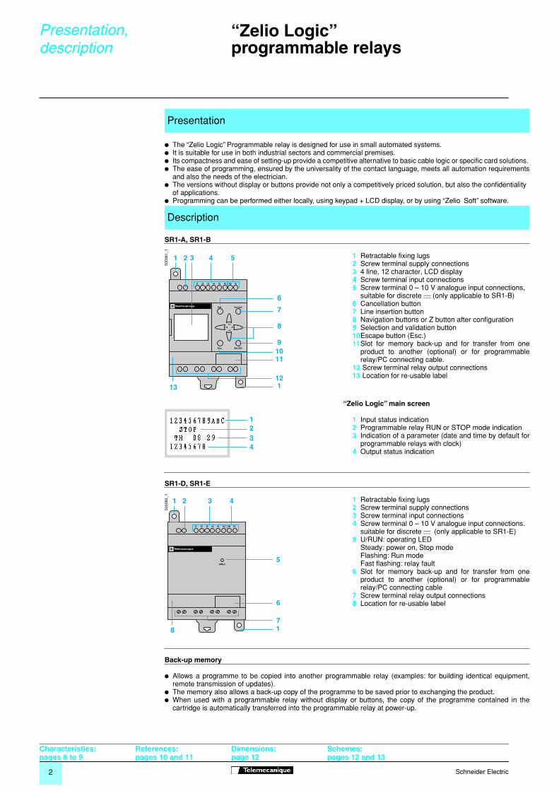
The “Zelio Logic” Programmable relay is designed for use in small automated systems.
p
It is suitable for use in both industrial sectors and commercial premises.
p
Its compactness and ease of setting-up provide a competitive alternative to basic cable logic or specific card solutions
.
p
The ease of programming, ensured by the universality of the contact language, meets all automation requirementsand also the needs of the electrician.
p
The versions without display or buttons provide not only a competitively priced solution, but also the confidentiality of applications.
p
Programming can be performed either locally, using keypad + LCD display, or by using “Zelio Soft” software.
SR1-A, SR1-B
1
Retractable fixing lugs
2
Screw terminal supply connections
3
4 line, 12 character, LCD display
4
Screw terminal input connections
5
Screw terminal 0 – 10 V analogue input connections,suitable for discrete
c
(only applicable to SR1-B)
6
Cancellation button
7
Line insertion button
8
Navigation buttons or Z button after configuration
9
Selection and validation button
10
Escape button (Esc.)
11
Slot for memory back-up and for transfer from oneproduct to another (optional) or for programmablerelay/PC connecting cable.
12
Screw terminal relay output connections
13
Location for re-usable label
“Zelio Logic” main screen
1
Input status indication
2
Programmable relay RUN or STOP mode indication
3
Indication of a parameter (date and time by default forprogrammable relays with clock)
4
Output status indication
SR1-D, SR1-E
1
Retractable fixing lugs
2
Screw terminal supply connections
3
Screw terminal input connections
4
Screw terminal 0 – 10 V analogue input connections.suitable for discrete
c
(only applicable to SR1-E)
5
U/RUN: operating LED Steady: power on, Stop mode Flashing: Run modeFast flashing: relay fault
6
Slot for memory back-up and for transfer from oneproduct to another (optional) or for programmablerelay/PC connecting cable
7
Screw terminal relay output connections
8
Location for re-usable label
p
Allows a programme to be copied into another programmable relay (examples: for building identical equipment,remote transmission of updates).
p
The memory also allows a back-up copy of the programme to be saved prior to exchanging the product.
p
When used with a programmable relay without display or buttons, the copy of the programme contained in thecartridge is automatically transferred into the programmable relay at power-up.
Presentation
Description
I1 I2 I3 I4 I5 I6
Del.
z1
z3z4 z2
Ins.line
Sel./OK
IB IC
Esc.
1 2 3 4 5
6
7
9
8
1011
12113
5003
81_1
1234
I1 I2 I3 I4 I5 I6
U/Run
IB IC
1 2 3 4
5
6
78 1
5003
82_1
Back-up memory
Presentation,description
Characteristics:pages 6 to 9
References:pages 10 and 11
Dimensions:page 12
Schemes: pages 12 and 13
3
Schneider Electric
1314 IxN/O
ix
N/C 22 21
oror
or
Ix
ixor
Ix
ix
Ix
ix
S
R
A1
A2
– KM1 (1)
A1
A2
1314
2324
Start
Stop
KM1
1314
or
I1
Q1
– KM1
I2
Start Stop
I1
Q1
– KM1
I2
Start Stop
Q
Q
Q
Q
A1
A2
A1
A2
Contact language
Example
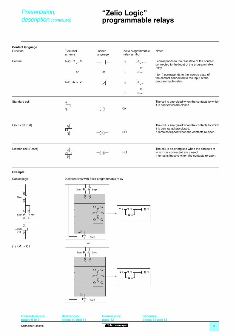
(1) KM1 = Q1
Function Electrical Ladder Zelio programmable Notesscheme language relay symbol
Contact I corresponds to the real state of the contactconnected to the input of the programmablerelay.
i (or I) corresponds to the inverse state ofthe contact connected to the input of theprogrammable relay.
Standard coil The coil is energised when the contacts to whichit is connected are closed.
Qx
Latch coil (Set) The coil is energised when the contacts to whichit is connected are closed.
SQ It remains tripped when the contacts re-open.
Unlatch coil (Reset) The coil is de-energised when the contacts to RQ which it is connected are closed.
It remains inactive when the contacts re-open.
Cabled logic 2 alternatives with Zelio programmable relay
“Zelio Logic”programmable relays
Presentation,description
(continued)
or
Characteristics:pages 6 to 9
References:pages 10 and 11
Dimensions:page 12
Schemes: pages 12 and 13
4
Schneider Electric
“Zelio Logic”programmable relays
Functions
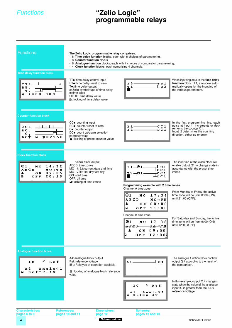
The Zelio Logic programmable relay comprises:
- 8
Time delay function
blocks, each with 8 choices of parametering,- 8
Counter function
blocks,- 8
Analogue function
blocks, each with 7 choices of comparator parametering,- 4
Clock function
blocks, each comprising 4 channels.
Time delay function block
TT
p
: time delay control input
When inputting data to the
time delay
function
block TT1, a window auto- matically opens for the inputting of the various parameters.
RT
p
: time delay reset to zeroT
p
: time delay outputa: Zelio symbol/type of time delays: time baset 00.00: time delay value
: locking of time delay value
Counter function block
CC
p
: counting inputRC
p
: counter reset to zeroIn the first programming line, eachpulse at input I1 increments or dec-rements the counter C1.Input I2 determines the counting direction, either up or down.
C
p
: counter outputDC
p
: count up/down selectionp: preset value
: locking of preset counter value
Clock function block
: clock block outputABCD: time zonesMO 14: 32: current date and timeMO –>TH: first day/last dayON: start timeOFF: off time
: locking of time zones
The insertion of the clock block will enable output Q1 to change state in accordance with the preset time zones.
Programming example with 2 time zones
Channel A time zoneFrom Monday to Friday, the active time zone will be from 8: 00 (ON) until 21: 00 (OFF).
Channel B time zoneFor Saturday and Sunday, the active time zone will be from 9: 00 (ON) until 12: 00 (OFF)
Analogue function block
A4: analogue block output
The analogue function block controls
output Q 4 according to the result of
the comparison.
Ref: reference voltageIB
≤
Ref: type of operation available
: locking of analogue block referencevalue
In this example, output Q 4 changes
state when the value of the analogue
input IC is greater than the 6.4 V reference voltage.
Functions
Characteristics:pages 6 to 9
References:pages 10 and 11
Dimensions:page 12
Schemes: pages 12 and 13
5
Schneider Electric
Modes
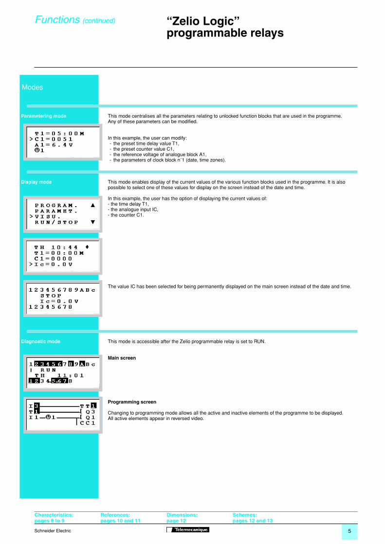
Parametering mode
This mode centralises all the parameters relating to unlocked function blocks that are used in the programme.Any of these parameters can be modified.
In this example, the user can modify:- the preset time delay value T1,- the preset counter value C1,- the reference voltage of analogue block A1,- the parameters of clock block n˚1 (date, time zones).
Display mode
This mode enables display of the current values of the various function blocks used in the programme. It is also possible to select one of these values for display on the screen instead of the date and time.
In this example, the user has the option of displaying the current values of:- the time delay T1,- the analogue input IC,- the counter C1.
The value IC has been selected for being permanently displayed on the main screen instead of the date and time.
Diagnostic mode
This mode is accessible after the Zelio programmable relay is set to RUN.
Main screen
Programming screen
Changing to programming mode allows all the active and inactive elements of the programme to be displayed.All active elements appear in reversed video.
Functions
(continued)
“Zelio Logic”programmable relays
Characteristics:pages 6 to 9
References:pages 10 and 11
Dimensions:page 12
Schemes: pages 12 and 13
6
Schneider Electric
“Zelio Logic”programmable relays
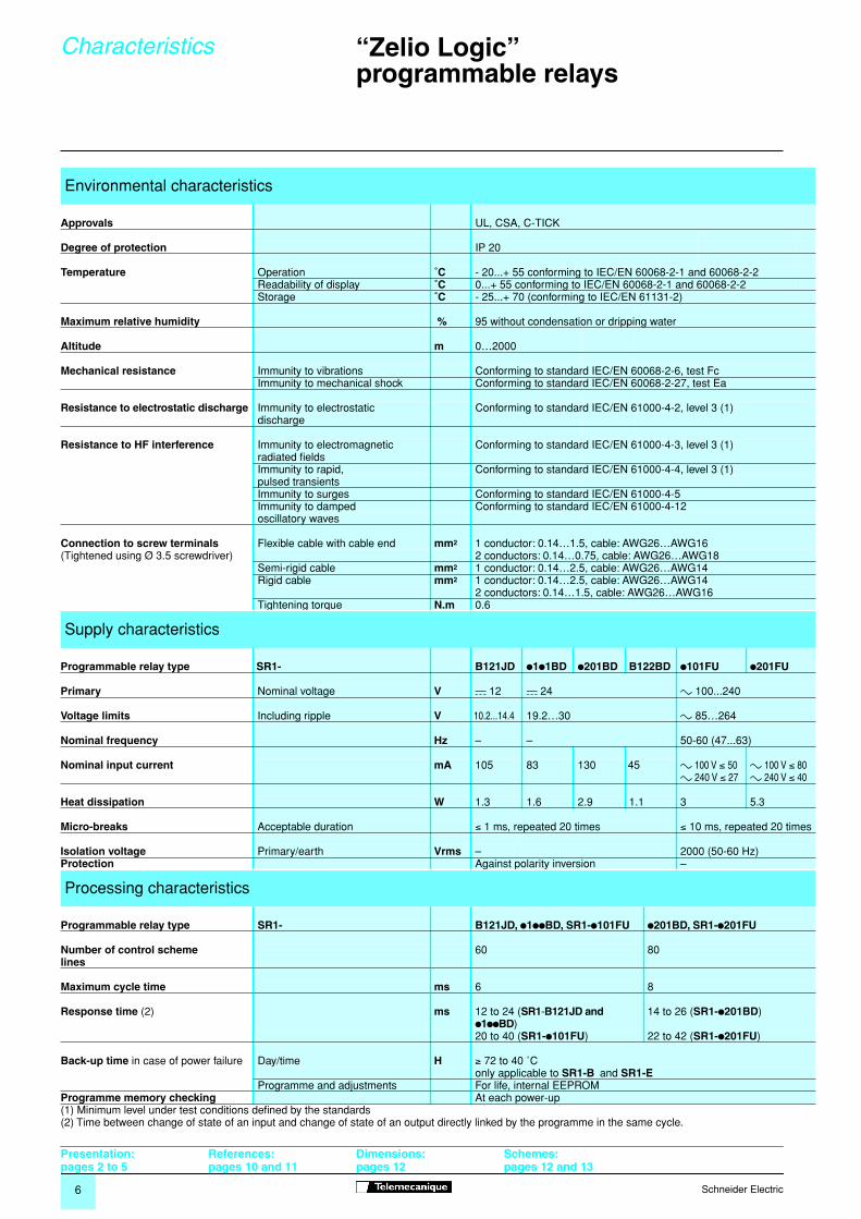
Environmental characteristics
Approvals
UL, CSA, C-TICK
Degree of protection
IP 20
Temperature
Operation
˚C
- 20...+ 55 conforming to IEC/EN 60068-2-1 and 60068-2-2Readability of display
˚C
0...+ 55 conforming to IEC/EN 60068-2-1 and 60068-2-2Storage
˚C
- 25...+ 70 (conforming to IEC/EN 61131-2)
Maximum relative humidity
%
95 without condensation or dripping water
Altitude m
0…2000
Mechanical resistance
Immunity to vibrations Conforming to standard IEC/EN 60068-2-6, test FcImmunity to mechanical shock Conforming to standard IEC/EN 60068-2-27, test Ea
Resistance to electrostatic discharge
Immunity to electrostatic Conforming to standard IEC/EN 61000-4-2, level 3 (1)discharge
Resistance to HF interference
Immunity to electromagnetic Conforming to standard IEC/EN 61000-4-3, level 3 (1)radiated fieldsImmunity to rapid, Conforming to standard IEC/EN 61000-4-4, level 3 (1)pulsed transientsImmunity to surges Conforming to standard IEC/EN 61000-4-5Immunity to damped Conforming to standard IEC/EN 61000-4-12oscillatory waves
Connection to screw terminals
Flexible cable with cable end
mm
2
1 conductor: 0.14…1.5, cable: AWG26…AWG16(Tightened using Ø 3.5 screwdriver) 2 conductors: 0.14…0.75, cable: AWG26…AWG18
Semi-rigid cable
mm
2
1 conductor: 0.14…2.5, cable: AWG26…AWG14Rigid cable
mm
2
1 conductor: 0.14…2.5, cable: AWG26…AWG142 conductors: 0.14…1.5, cable: AWG26…AWG16
Tightening torque
N.m
0.6
Supply characteristics
Programmable relay type SR1- B121JD
p
1
p
1BD
p
201BD B122BD
p
101FU
p
201FU
Primary
Nominal voltage
V
c
12
c
24 a 100...240
Voltage limits Including ripple V 10.2...14.4 19.2…30 a 85…264
Nominal frequency Hz – – 50-60 (47...63)
Nominal input current mA 105 83 130 45 a 100 V ≤ 50 a 100 V ≤ 80a 240 V ≤ 27 a 240 V ≤ 40
Heat dissipation W 1.3 1.6 2.9 1.1 3 5.3
Micro-breaks Acceptable duration ≤ 1 ms, repeated 20 times ≤ 10 ms, repeated 20 times
Isolation voltage Primary/earth Vrms – 2000 (50-60 Hz)Protection Against polarity inversion –
Processing characteristics
Programmable relay type SR1- B121JD, p1ppBD, SR1-p101FU p201BD, SR1-p201FU
Number of control scheme 60 80lines
Maximum cycle time ms 6 8
Response time (2) ms 12 to 24 (SR1-B121JD and p1ppBD)
14 to 26 (SR1-p201BD)
20 to 40 (SR1-p101FU) 22 to 42 (SR1-p201FU)
Back-up time in case of power failure Day/time H ≥ 72 to 40 ˚Conly applicable to SR1-B and SR1-E
Programme and adjustments For life, internal EEPROMProgramme memory checking At each power-up(1) Minimum level under test conditions defined by the standards(2) Time between change of state of an input and change of state of an output directly linked by the programme in the same cycle.
Characteristics
Presentation:pages 2 to 5
References:pages 10 and 11
Dimensions:pages 12
Schemes: pages 12 and 13
7Schneider Electric
“Zelio Logic”programmable relays
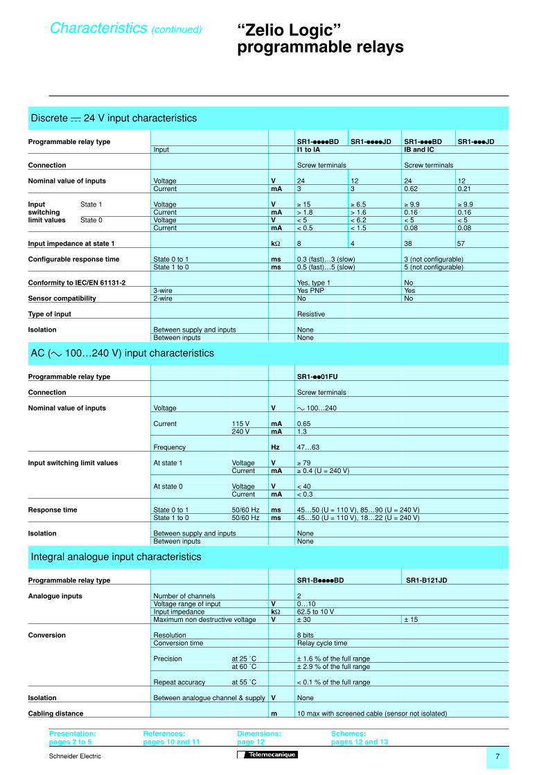
Discrete c 24 V input characteristics
Programmable relay type SR1-ppppBD SR1-ppppJD SR1-pppBD SR1-pppJDInput I1 to IA IB and IC
Connection Screw terminals Screw terminals
Nominal value of inputs Voltage V 24 12 24 12Current mA 3 3 0.62 0.21
Input State 1 Voltage V ≥ 15 ≥ 6.5 ≥ 9.9 ≥ 9.9switching Current mA > 1.8 > 1.6 0.16 0.16limit values State 0 Voltage V < 5 < 6.2 < 5 < 5
Current mA < 0.5 < 1.5 0.08 0.08
Input impedance at state 1 kΩ 8 4 38 57
Configurable response time State 0 to 1 ms 0.3 (fast)…3 (slow) 3 (not configurable)State 1 to 0 ms 0.5 (fast)…5 (slow) 5 (not configurable)
Conformity to IEC/EN 61131-2 Yes, type 1 No3-wire Yes PNP Yes
Sensor compatibility 2-wire No No
Type of input Resistive
Isolation Between supply and inputs NoneBetween inputs None
AC (a 100…240 V) input characteristics
Programmable relay type SR1-pp01FU
Connection Screw terminals
Nominal value of inputs Voltage V a 100…240
Current 115 V mA 0.65 240 V mA 1.3
Frequency Hz 47…63
Input switching limit values At state 1 Voltage V ≥ 79Current mA ≥ 0.4 (U = 240 V)
At state 0 Voltage V < 40 Current mA < 0.3
Response time State 0 to 1 50/60 Hz ms 45…50 (U = 110 V), 85…90 (U = 240 V)State 1 to 0 50/60 Hz ms 45…50 (U = 110 V), 18…22 (U = 240 V)
Isolation Between supply and inputs NoneBetween inputs None
Integral analogue input characteristics
Programmable relay type SR1-BppppBD SR1-B121JD
Analogue inputs Number of channels 2Voltage range of input V 0…10Input impedance kΩ 62.5 to 10 VMaximum non destructive voltage V ± 30 ± 15
Conversion Resolution 8 bitsConversion time Relay cycle time
Precision at 25 ˚C ± 1.6 % of the full rangeat 60 ˚C ± 2.9 % of the full range
Repeat accuracy at 55 ˚C < 0.1 % of the full range
Isolation Between analogue channel & supply V None
Cabling distance m 10 max with screened cable (sensor not isolated)
Characteristics (continued)
Presentation:pages 2 to 5
References:pages 10 and 11
Dimensions:page 12
Schemes: pages 12 and 13
8 Schneider Electric
“Zelio Logic”programmable relays
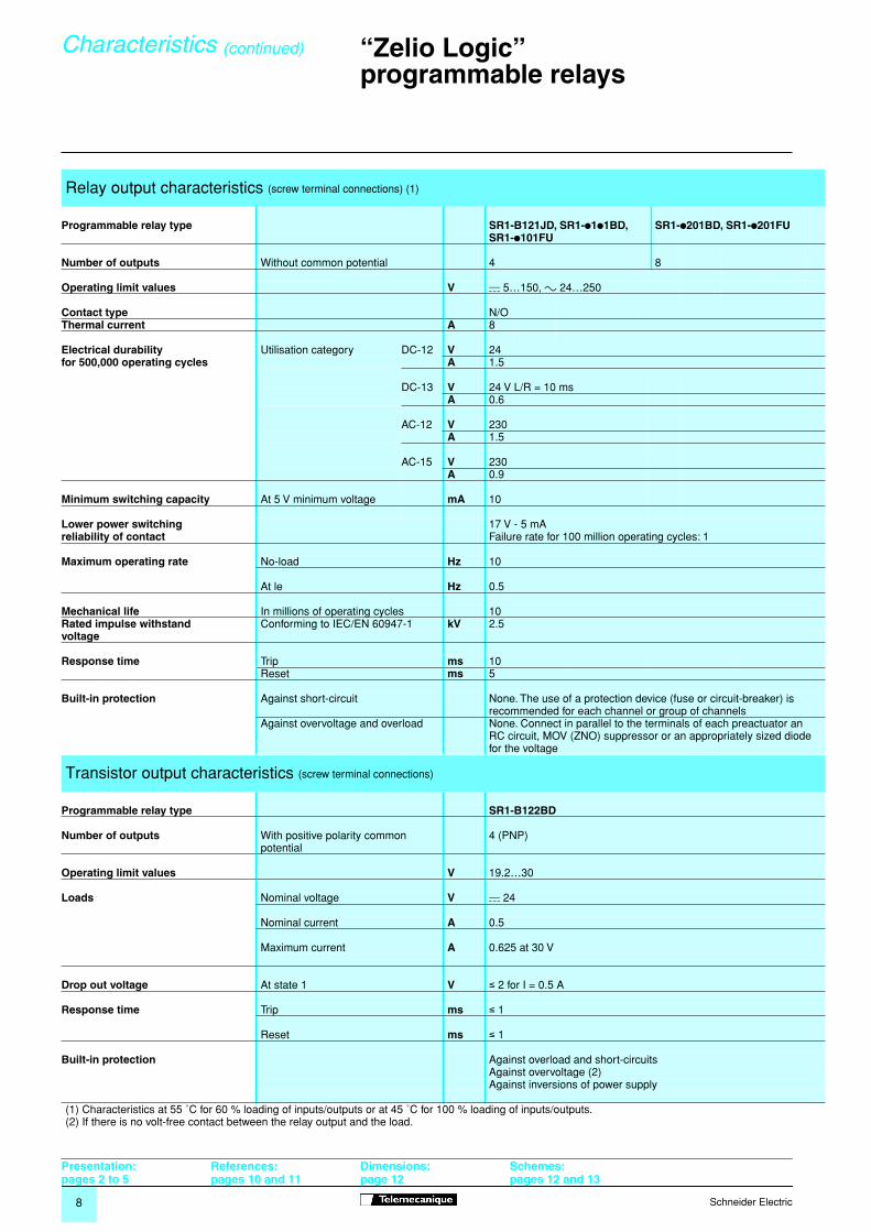
Relay output characteristics (screw terminal connections) (1)
Programmable relay type SR1-B121JD, SR1-p1p1BD, SR1-p101FU
SR1-p201BD, SR1-p201FU
Number of outputs Without common potential 4 8
Operating limit values V c 5…150, a 24…250
Contact type N/OThermal current A 8
Electrical durability Utilisation category DC-12 V 24for 500,000 operating cycles A 1.5
DC-13 V 24 V L/R = 10 msA 0.6
AC-12 V 230A 1.5
AC-15 V 230A 0.9
Minimum switching capacity At 5 V minimum voltage mA 10
Lower power switching 17 V - 5 mAreliability of contact Failure rate for 100 million operating cycles: 1
Maximum operating rate No-load Hz 10
At le Hz 0.5
Mechanical life In millions of operating cycles 10Rated impulse withstand Conforming to IEC/EN 60947-1 kV 2.5voltage
Response time Trip ms 10Reset ms 5
Built-in protection Against short-circuit None. The use of a protection device (fuse or circuit-breaker) is recommended for each channel or group of channels
Against overvoltage and overload None. Connect in parallel to the terminals of each preactuator an RC circuit, MOV (ZNO) suppressor or an appropriately sized diode for the voltage
Transistor output characteristics (screw terminal connections)
Programmable relay type SR1-B122BD
Number of outputs With positive polarity common potential
4 (PNP)
Operating limit values V 19.2…30
Loads Nominal voltage V c 24
Nominal current A 0.5
Maximum current A 0.625 at 30 V
Drop out voltage At state 1 V ≤ 2 for I = 0.5 A
Response time Trip ms ≤ 1
Reset ms ≤ 1
Built-in protection Against overload and short-circuitsAgainst overvoltage (2)Against inversions of power supply
(1) Characteristics at 55 ˚C for 60 % loading of inputs/outputs or at 45 ˚C for 100 % loading of inputs/outputs.(2) If there is no volt-free contact between the relay output and the load.
Characteristics (continued)
Presentation:pages 2 to 5
References:pages 10 and 11
Dimensions:page 12
Schemes: pages 12 and 13

10 Schneider Electric
“Zelio Logic”programmable relays
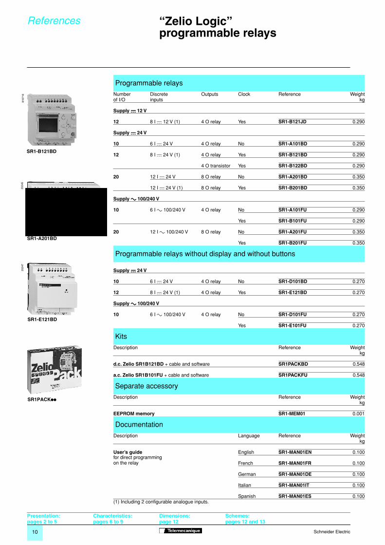
(1) Including 2 configurable analogue inputs.
Programmable relays
Number Discrete Outputs Clock Reference Weightof I/O inputs kg
Supply cccc 12 V
12 8 I c 12 V (1) 4 O relay Yes SR1-B121JD 0.290
Supply cccc 24 V
10 6 I c 24 V 4 O relay No SR1-A101BD 0.290
12 8 I c 24 V (1) 4 O relay Yes SR1-B121BD 0.290
4 O transistor Yes SR1-B122BD 0.290
20 12 I c 24 V 8 O relay No SR1-A201BD 0.350
12 I c 24 V (1) 8 O relay Yes SR1-B201BD 0.350
Supply aaaa 100/240 V
10 6 I a 100/240 V 4 O relay No SR1-A101FU 0.290
Yes SR1-B101FU 0.290
20 12 I a 100/240 V 8 O relay No SR1-A201FU 0.350
Yes SR1-B201FU 0.350
Programmable relays without display and without buttons
Supply cccc 24 V
10 6 I c 24 V 4 O relay No SR1-D101BD 0.270
12 8 I c 24 V (1) 4 O relay Yes SR1-E121BD 0.270
Supply aaaa 100/240 V
10 6 I a 100/240 V 4 O relay No SR1-D101FU 0.270
Yes SR1-E101FU 0.270
Kits
Description Reference Weightkg
d.c. Zelio SR1B121BD + cable and software SR1PACKBD 0.548
a.c. Zelio SR1B101FU + cable and software SR1PACKFU 0.548
Separate accessory
Description Reference Weightkg
EEPROM memory SR1-MEM01 0.001
Documentation
Description Language Reference Weightkg
User’s guidefor direct programming on the relay
English SR1-MAN01EN 0.100
French SR1-MAN01FR 0.100
German SR1-MAN01DE 0.100
Italian SR1-MAN01IT 0.100
Spanish SR1-MAN01ES 0.100
SR1-B121BD
8167
16
SR1-A201BD
2024
5
SR1-E121BD
2024
7
SR1PACKpp
References
Presentation:pages 2 to 5
Characteristics:pages 6 to 9
Dimensions:page 12
Schemes: pages 12 and 13
11Schneider Electric
“Zelio Logic”programmable relays
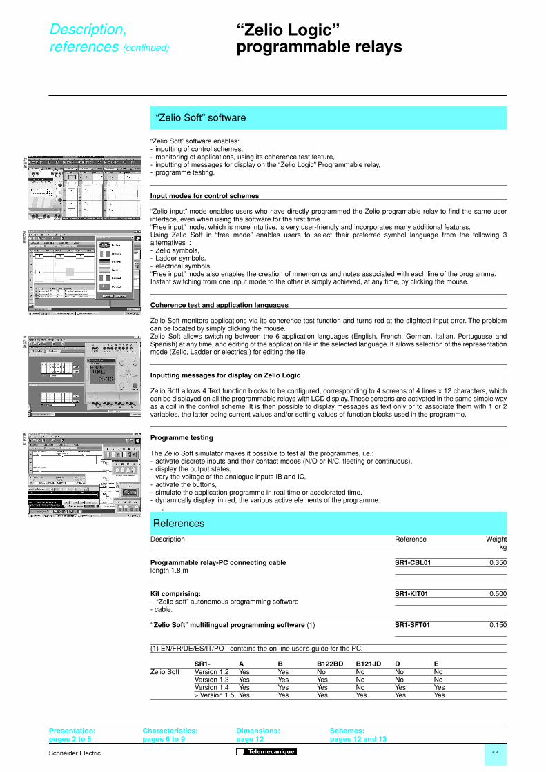
“Zelio Soft” software enables:- inputting of control schemes,- monitoring of applications, using its coherence test feature,- inputting of messages for display on the “Zelio Logic” Programmable relay,- programme testing.
Input modes for control schemes
“Zelio input” mode enables users who have directly programmed the Zelio programable relay to find the same userinterface, even when using the software for the first time.“Free input” mode, which is more intuitive, is very user-friendly and incorporates many additional features. Using Zelio Soft in “free mode” enables users to select their preferred symbol language from the following 3alternatives : - Zelio symbols,- Ladder symbols,- electrical symbols.“Free input” mode also enables the creation of mnemonics and notes associated with each line of the programme.Instant switching from one input mode to the other is simply achieved, at any time, by clicking the mouse.
Coherence test and application languages
Zelio Soft monitors applications via its coherence test function and turns red at the slightest input error. The problemcan be located by simply clicking the mouse. Zelio Soft allows switching between the 6 application languages (English, French, German, Italian, Portuguese andSpanish) at any time, and editing of the application file in the selected language. It allows selection of the representationmode (Zelio, Ladder or electrical) for editing the file.
Inputting messages for display on Zelio Logic
Zelio Soft allows 4 Text function blocks to be configured, corresponding to 4 screens of 4 lines x 12 characters, whichcan be displayed on all the programmable relays with LCD display. These screens are activated in the same simple wayas a coil in the control scheme. It is then possible to display messages as text only or to associate them with 1 or 2variables, the latter being current values and/or setting values of function blocks used in the programme.
Programme testing
The Zelio Soft simulator makes it possible to test all the programmes, i.e.:- activate discrete inputs and their contact modes (N/O or N/C, fleeting or continuous),- display the output states,- vary the voltage of the analogue inputs IB and IC,- activate the buttons,- simulate the application programme in real time or accelerated time,- dynamically display, in red, the various active elements of the programme. .
“Zelio Soft” software
8167
2181
6720
8167
1981
6718
References
Description Reference Weightkg
Programmable relay-PC connecting cable SR1-CBL01 0.350length 1.8 m
Kit comprising: SR1-KIT01 0.500- “Zelio soft” autonomous programming software- cable.
“Zelio Soft” multilingual programming software (1) SR1-SFT01 0.150
(1) EN/FR/DE/ES/IT/PO - contains the on-line user’s guide for the PC.
SR1- A B B122BD B121JD D EZelio Soft Version 1.2 Yes Yes No No No No
Version 1.3 Yes Yes Yes No No NoVersion 1.4 Yes Yes Yes No Yes Yes≥ Version 1.5 Yes Yes Yes Yes Yes Yes
Description,references (continued)
Presentation:pages 2 to 5
Characteristics:pages 6 to 9
Dimensions:page 12
Schemes: pages 12 and 13
13Schneider Electric
“Zelio Logic”programmable relays
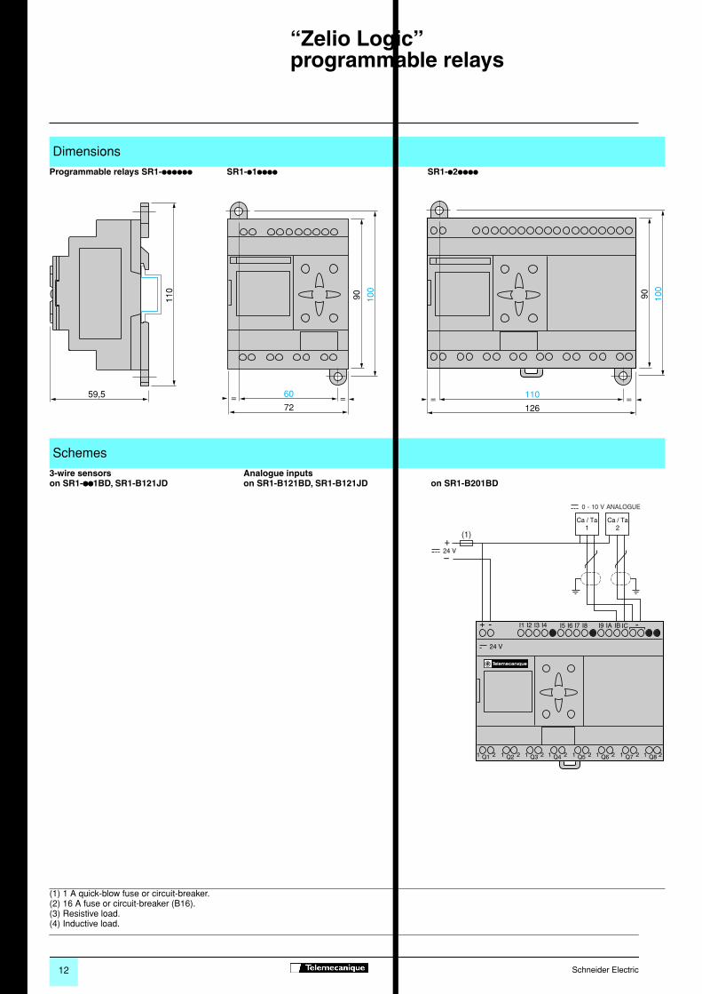
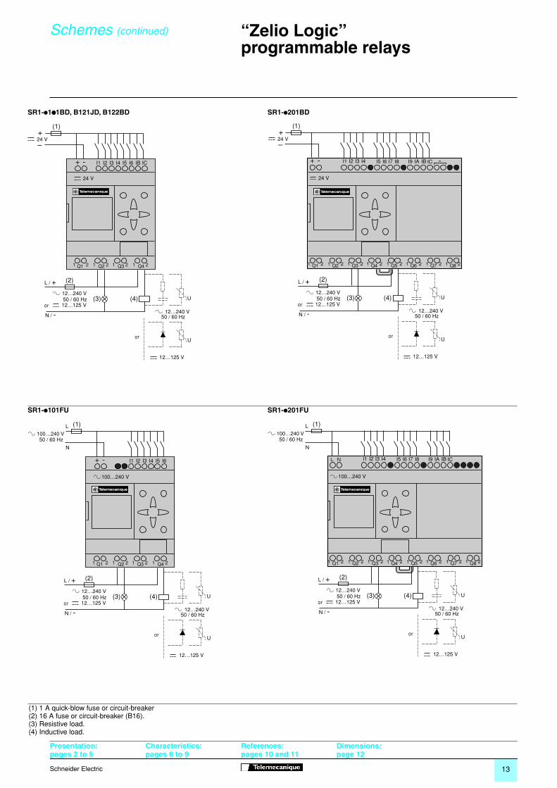
(1) 1 A quick-blow fuse or circuit-breaker(2) 16 A fuse or circuit-breaker (B16).(3) Resistive load.(4) Inductive load.
SR1-p1pppp1BD, B121JD, B122BD SR1-p201BD
SR1-p101FU SR1-p201FU
+ - I1 I2 I3 I4 I5 I6 IB IC
1 Q1 2 1 Q2 2 1 Q3 2 1 Q4 2
24 V
or
L / +
N / -
U
12…240 V50 / 60 Hz
(2)
(3)
U
12…125 V
(4)or
12…240 V50 / 60 Hz12…125 V
(1)+24 V–
Q1 Q2 Q3 Q4 Q5 Q6 Q7 Q81 2 1 2 1 2 1 2 1 2 1 2 1 2 1 2
+ - I1 I2 I3 I4 I5 I6 I7 I8 I9 IA IB IC -
24 V
or
L / +
N / -
U
12…240 V50 / 60 Hz
(2)
(3)
U
12…125 V
(4)or
12…240 V50 / 60 Hz12…125 V
(1)+24 V–
+ - I1 I2 I3 I4 I5 I6
1 Q1 2 1 Q2 2 1 Q3 2 1 Q4 2
or
L / +
N / -
U
12…240 V50 / 60 Hz
(2)
(3)
U
12…125 V
(4)or
12…240 V50 / 60 Hz12…125 V
100…240 V
(1)100…240 V 50 / 60 Hz
L
N
Q1 Q2 Q3 Q4 Q5 Q6 Q7 Q81 2 1 2 1 2 1 2 1 2 1 2 1 2 1 2
I1 I2 I3 I4 I5 I6 I7 I8 I9 IA IB IC
or
L / +
N / -
U
12…240 V50 / 60 Hz
(2)
(3)
U
12…125 V
(4)or
12…240 V50 / 60 Hz12…125 V
100…240 V
L N
(1)100…240 V 50 / 60 Hz
L
N
Schemes (continued)
Presentation:pages 2 to 5
Characteristics:pages 6 to 9
References:pages 10 and 11
Dimensions: page 12


![[ 3000 Series Time Delay Relays and Measuring Relays ... · [ 3000 Series Time Delay Relays and Measuring Relays ] ... Measuring Relays ] • Time Delay Relays ... Dear Reader, Dear](https://img.dokumen.tips/doc/110x75/5b85683b7f8b9aec488e43dd/-3000-series-time-delay-relays-and-measuring-relays-3000-series-time.jpg)