Embed Size (px)
Citation preview
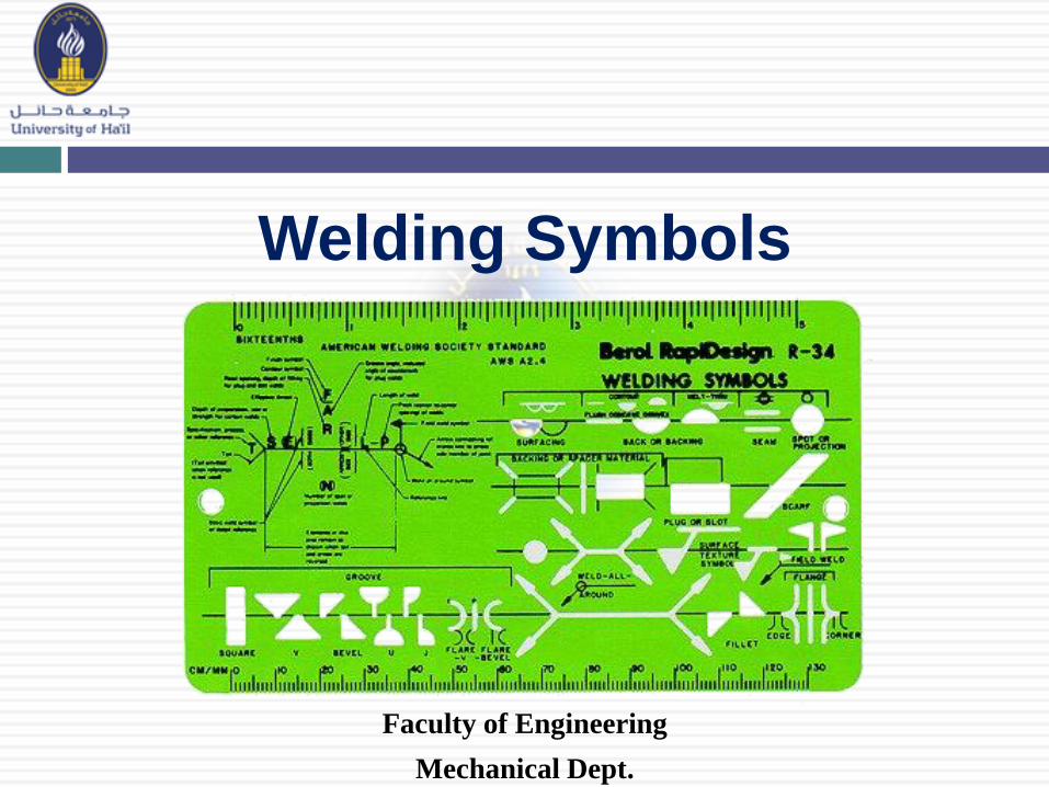
Faculty of Engineering
Mechanical Dept.
Welding Symbols

Objectives
1. Know the name of the AWS & ISO standards for welding symbols
2. List the eight elements that may be found on a welding symbol
3. List the basic weld symbols
4. List the supplementary symbols
5. Identify the applications of the different weld symbols
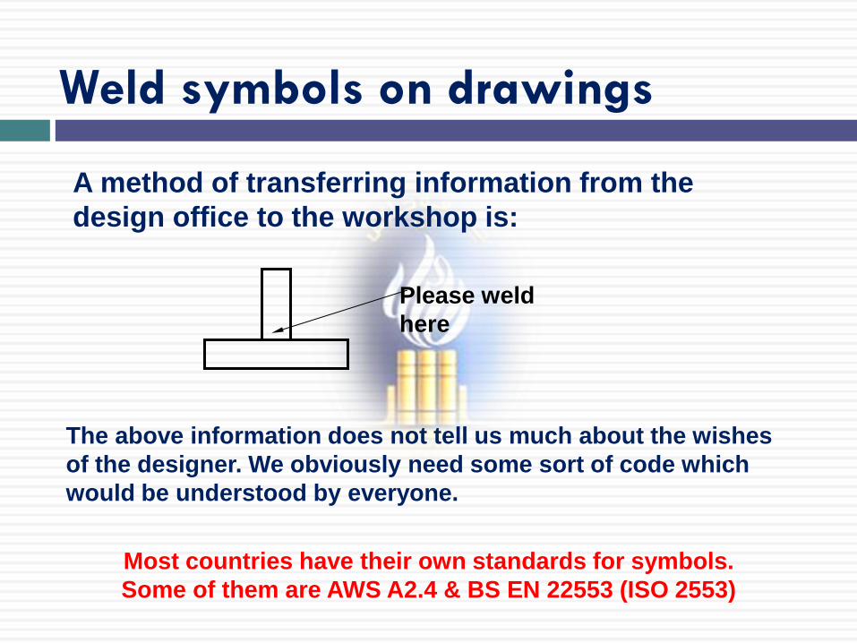
A method of transferring information from the
design office to the workshop is:
The above information does not tell us much about the wishes
of the designer. We obviously need some sort of code which
would be understood by everyone.
Most countries have their own standards for symbols.
Some of them are AWS A2.4 & BS EN 22553 (ISO 2553)
Please weld
here
Weld symbols on drawings
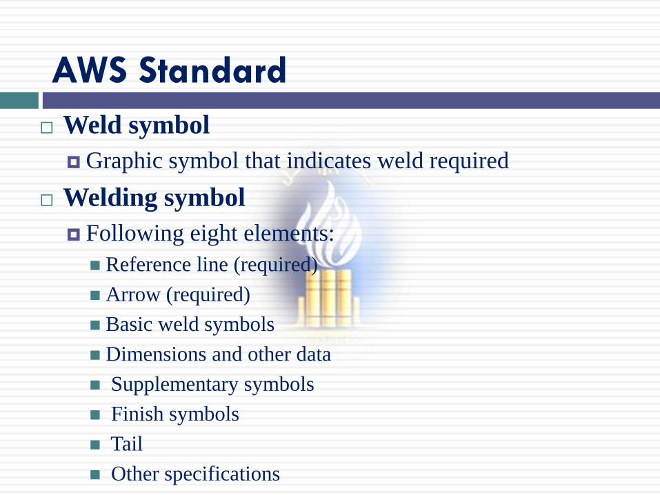
AWS Standard
Weld symbol
Graphic symbol that indicates weld required
Welding symbol
Following eight elements:
Reference line (required)
Arrow (required)
Basic weld symbols
Dimensions and other data
Supplementary symbols
Finish symbols
Tail
Other specifications
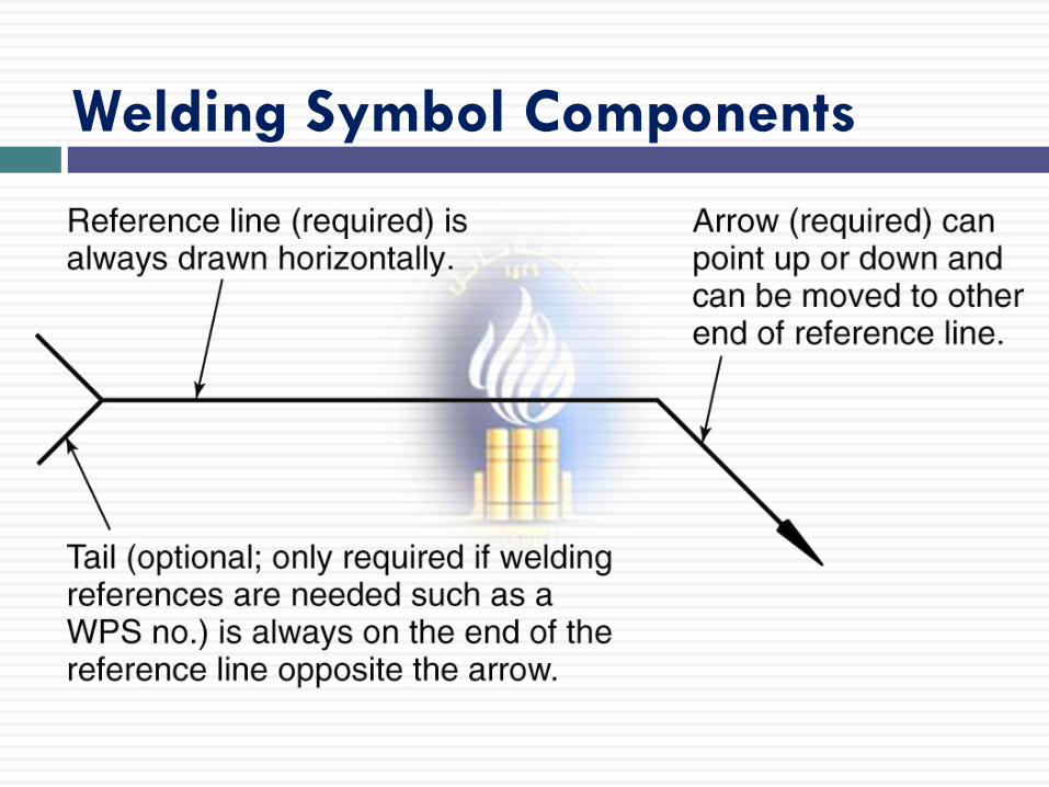
Welding Symbol Components
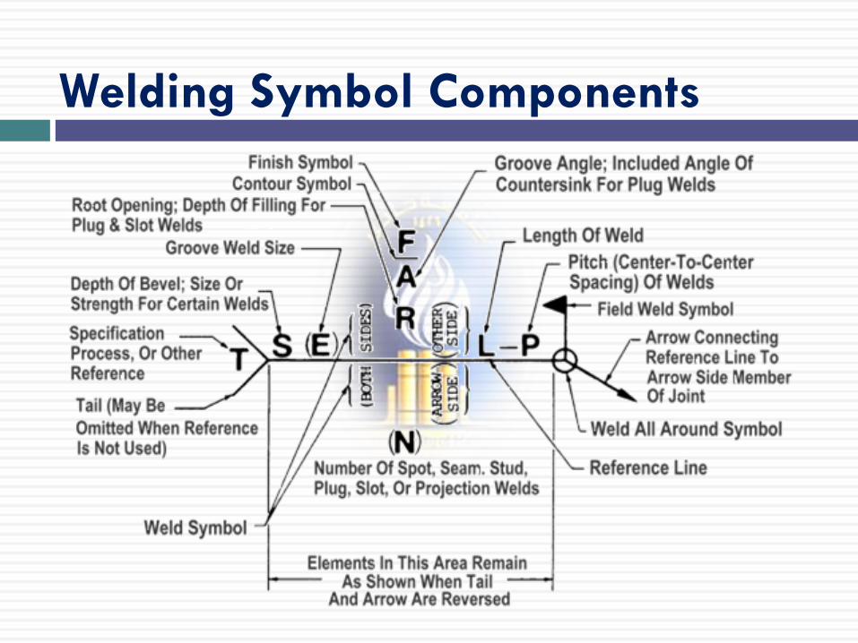
Welding Symbol Components

Welding Symbol Components
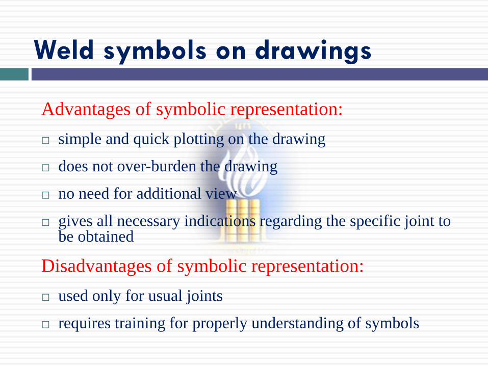
Advantages of symbolic representation:
simple and quick plotting on the drawing
does not over-burden the drawing
no need for additional view
gives all necessary indications regarding the specific joint to be obtained
Disadvantages of symbolic representation:
used only for usual joints
requires training for properly understanding of symbols
Weld symbols on drawings
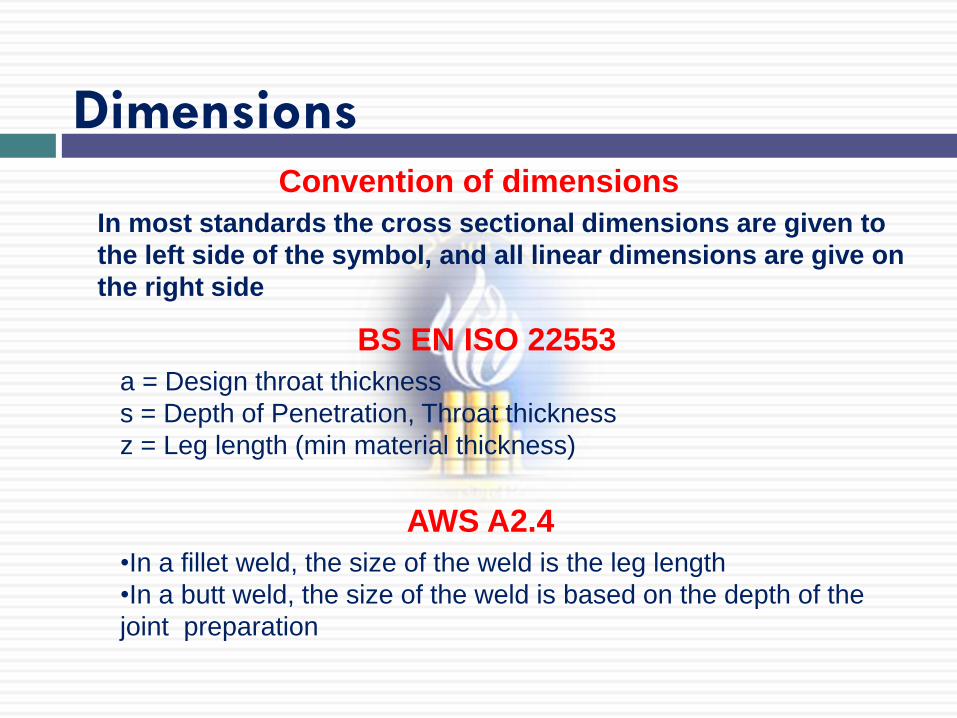
In most standards the cross sectional dimensions are given to
the left side of the symbol, and all linear dimensions are give on
the right side
Dimensions Convention of dimensions
a = Design throat thickness
s = Depth of Penetration, Throat thickness
z = Leg length (min material thickness)
BS EN ISO 22553
AWS A2.4
•In a fillet weld, the size of the weld is the leg length
•In a butt weld, the size of the weld is based on the depth of the
joint preparation

Joints in drawings may be indicated:
•by detailed sketches, showing every dimension
•by symbolic representation
Weld symbols on drawings
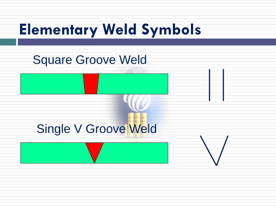
Elementary Weld Symbols
Square Groove Weld
Single V Groove Weld
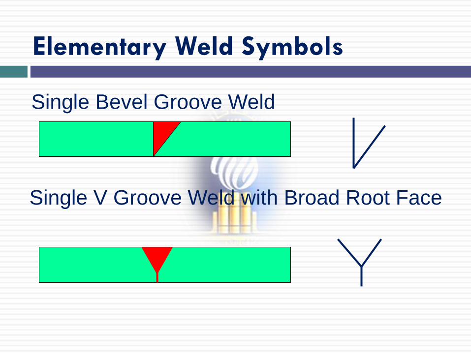
Single Bevel Groove Weld
Single V Groove Weld with Broad Root Face
Elementary Weld Symbols
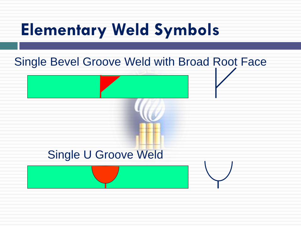
Single Bevel Groove Weld with Broad Root Face
Single U Groove Weld
Elementary Weld Symbols
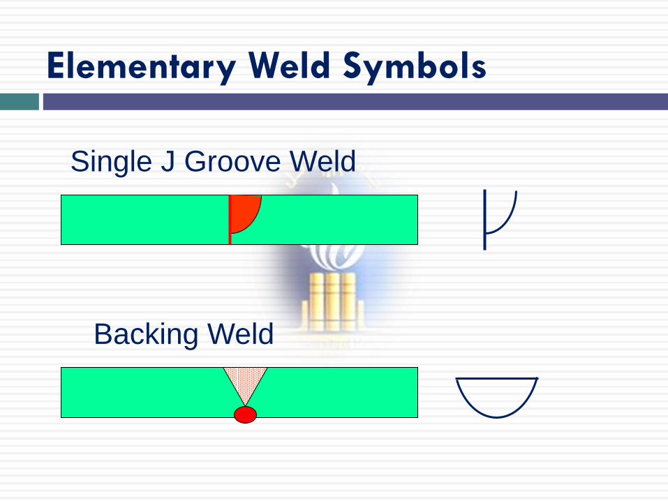
Single J Groove Weld
Backing Weld
Elementary Weld Symbols
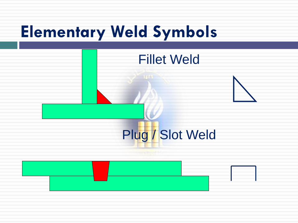
Fillet Weld
Plug / Slot Weld
Elementary Weld Symbols
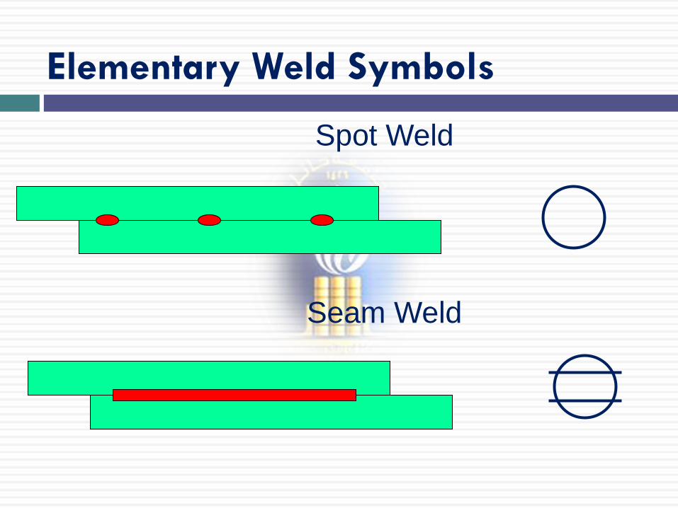
Spot Weld
Seam Weld
Elementary Weld Symbols
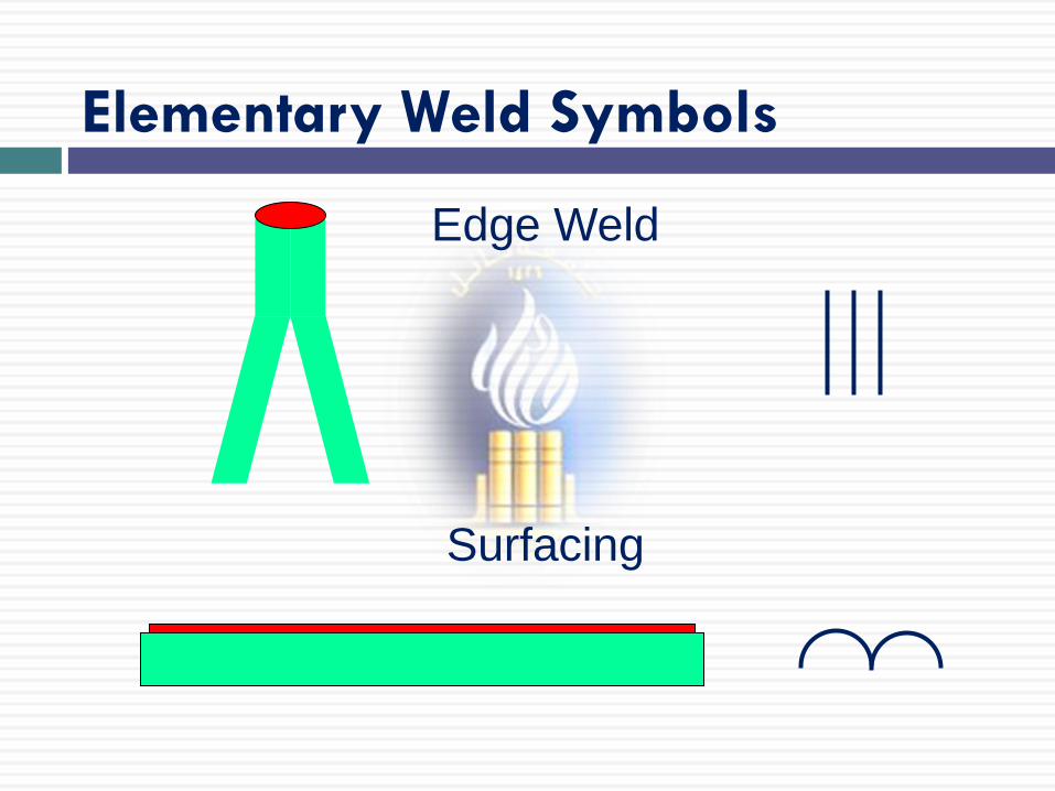
Edge Weld
Surfacing
Elementary Weld Symbols
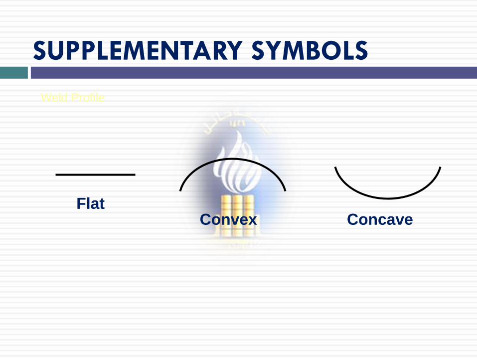
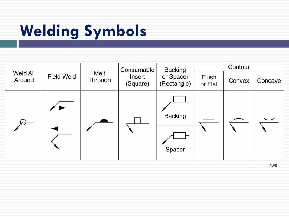
SUPPLEMENTARY SYMBOLS
Flat Convex Concave
Weld Profile
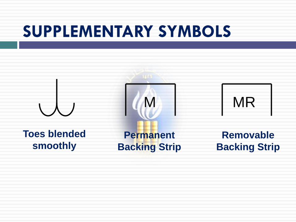
SUPPLEMENTARY SYMBOLS
Toes blended
smoothly Permanent
Backing Strip
M
Removable
Backing Strip
MR
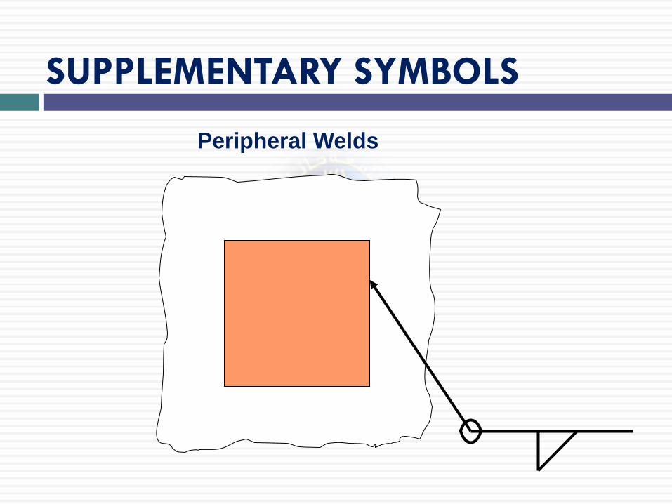
SUPPLEMENTARY SYMBOLS
Peripheral Welds
Basic Weld Symbols
AWS
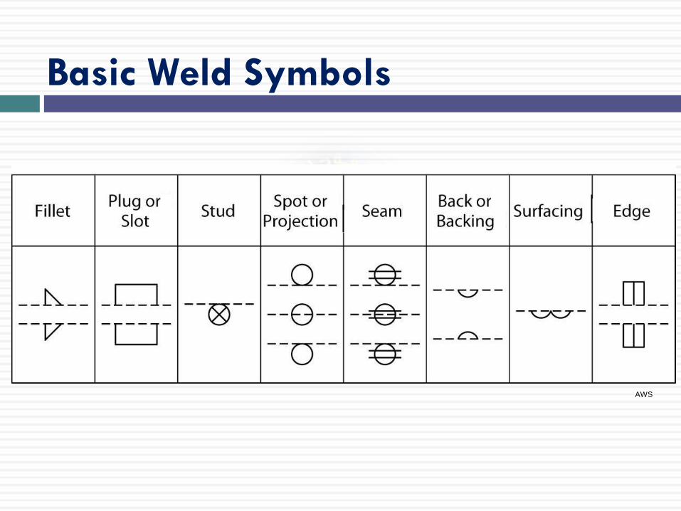
Basic Weld Symbols
AWS
Welding Symbols
AWS

24 of 691
Plug weld
Resistance spot weld
Resistance seam weld
Square Butt weld
Steep flanked
Single-V Butt
Surfacing
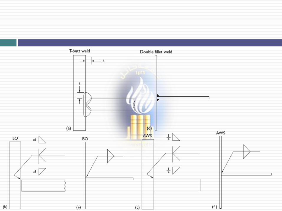
ISO 2553 / BS EN 22553
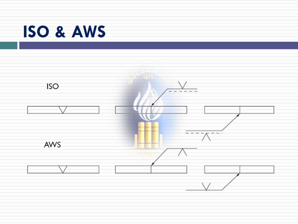
ISO & AWS
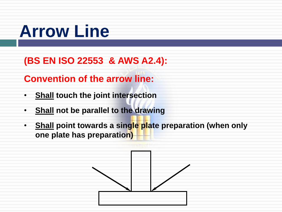
Arrow Line
(BS EN ISO 22553 & AWS A2.4):
Convention of the arrow line:
• Shall touch the joint intersection
• Shall not be parallel to the drawing
• Shall point towards a single plate preparation (when only
one plate has preparation)
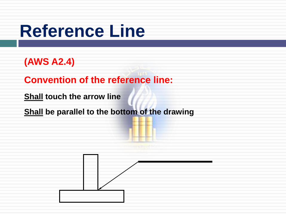
(AWS A2.4)
Convention of the reference line:
Shall touch the arrow line
Shall be parallel to the bottom of the drawing
Reference Line
or
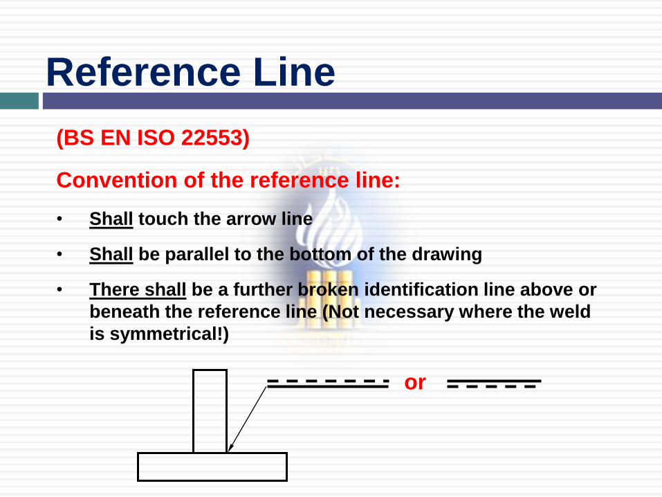
Reference Line
(BS EN ISO 22553)
Convention of the reference line:
• Shall touch the arrow line
• Shall be parallel to the bottom of the drawing
• There shall be a further broken identification line above or
beneath the reference line (Not necessary where the weld
is symmetrical!)
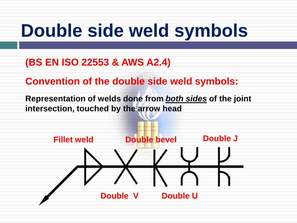
(BS EN ISO 22553 & AWS A2.4)
Convention of the double side weld symbols:
Representation of welds done from both sides of the joint
intersection, touched by the arrow head
Fillet weld
Double V
Double bevel
Double U
Double J
Double side weld symbols
30 of 691
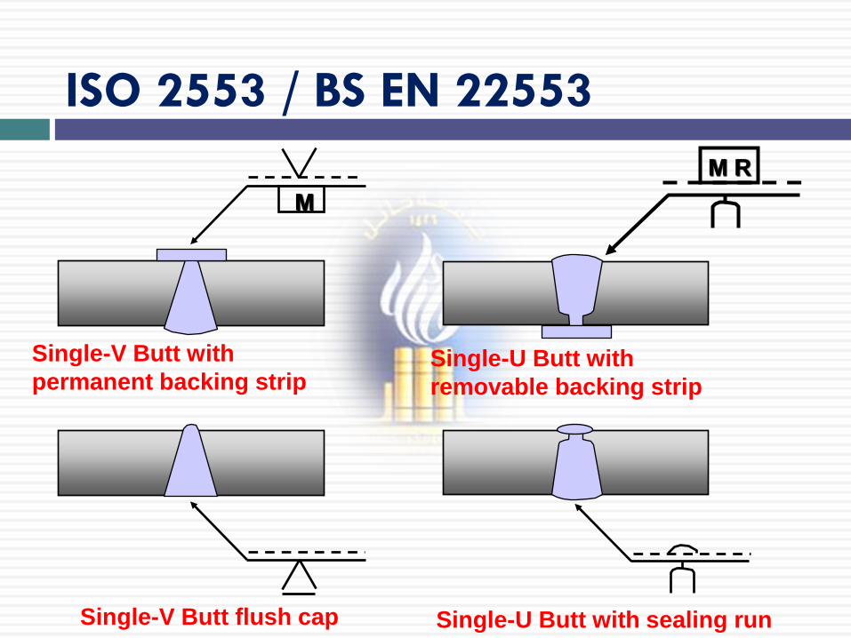
Single-V Butt flush cap Single-U Butt with sealing run
Single-V Butt with
permanent backing strip
M
Single-U Butt with
removable backing strip
M R
ISO 2553 / BS EN 22553
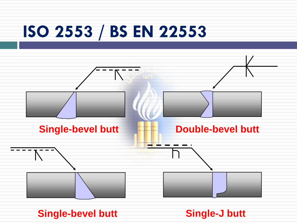
31 of 691
Single-bevel butt Double-bevel butt
Single-bevel butt Single-J butt
ISO 2553 / BS EN 22553
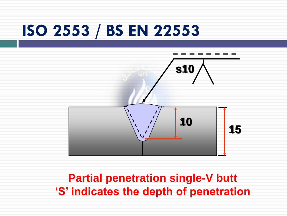
Partial penetration single-V butt
‘S’ indicates the depth of penetration
s10
10 15
ISO 2553 / BS EN 22553
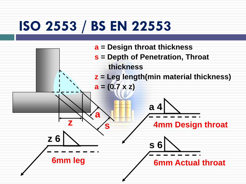
33 of 691 a = Design throat thickness
s = Depth of Penetration, Throat
thickness
z = Leg length(min material thickness)
a = (0.7 x z)
a 4
4mm Design throat
z 6
6mm leg
a z s
s 6
6mm Actual throat
ISO 2553 / BS EN 22553

34 of 691
ISO 2553 / BS EN 22553
Arrow side
Arrow side
35 of 691
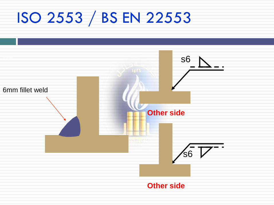
Other side
ISO 2553 / BS EN 22553
Other side
s6
s6
6mm fillet weld
36 of 691
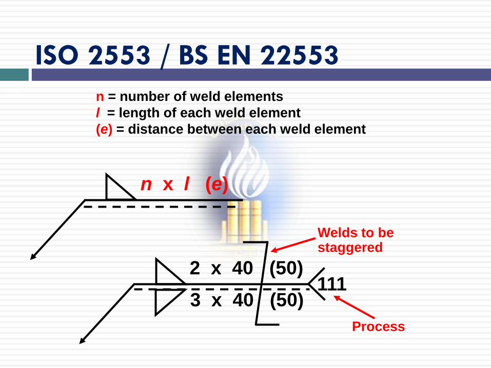
n = number of weld elements
l = length of each weld element
(e) = distance between each weld element
n x l (e)
Welds to be staggered
Process
2 x 40 (50)
3 x 40 (50) 111
ISO 2553 / BS EN 22553
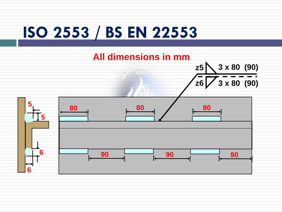
80 80 80
90 90 90
6
6
5
5
z5
z6
3 x 80 (90)
3 x 80 (90)
ISO 2553 / BS EN 22553
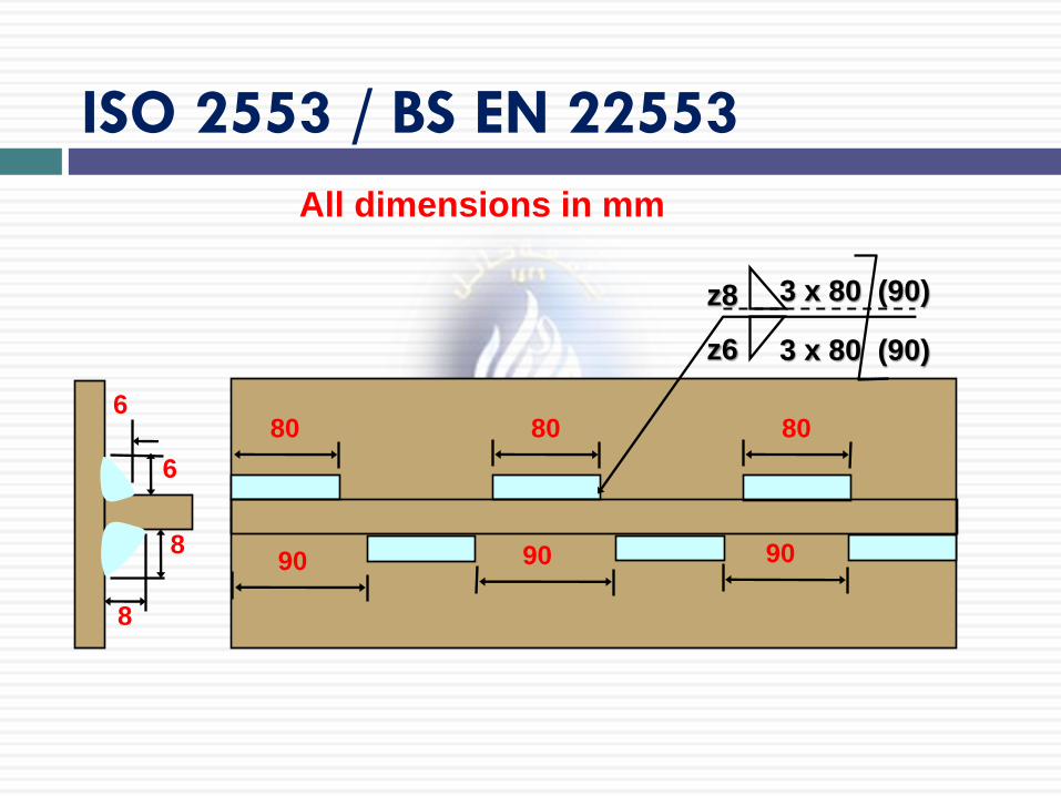
All dimensions in mm
ISO 2553 / BS EN 22553
All dimensions in mm
8
8
6
6 80 80 80
90 90 90
z8
z6
3 x 80 (90)
3 x 80 (90)
Supplementary symbols
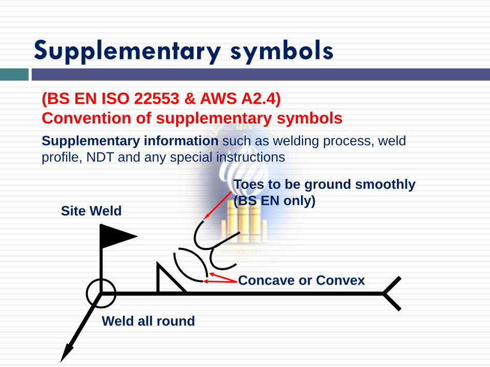
Concave or Convex
Toes to be ground smoothly
(BS EN only) Site Weld
Weld all round
(BS EN ISO 22553 & AWS A2.4)
Convention of supplementary symbols
Supplementary information such as welding process, weld
profile, NDT and any special instructions
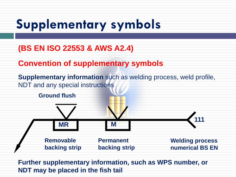
Supplementary symbols
Further supplementary information, such as WPS number, or
NDT may be placed in the fish tail
Ground flush
111
Welding process
numerical BS EN
MR
Removable
backing strip
Permanent
backing strip
M
(BS EN ISO 22553 & AWS A2.4)
Convention of supplementary symbols
Supplementary information such as welding process, weld profile,
NDT and any special instructions
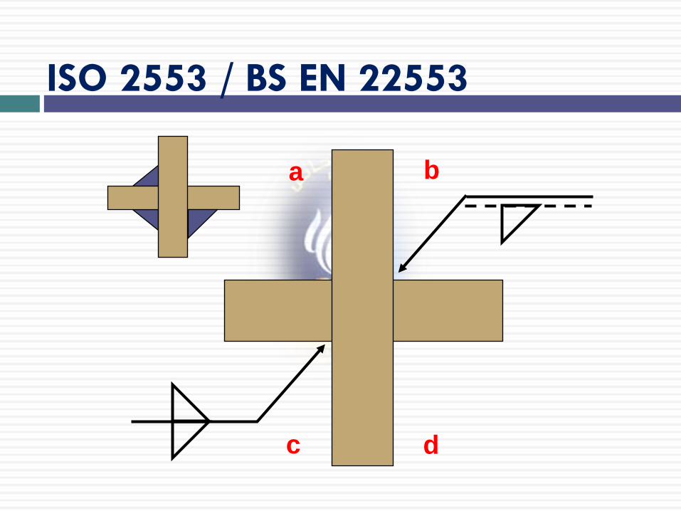
41 of 691
b a
d c
ISO 2553 / BS EN 22553
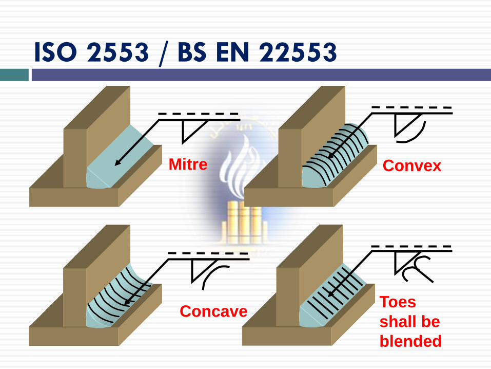
Convex Mitre
Toes
shall be
blended
ISO 2553 / BS EN 22553
Concave
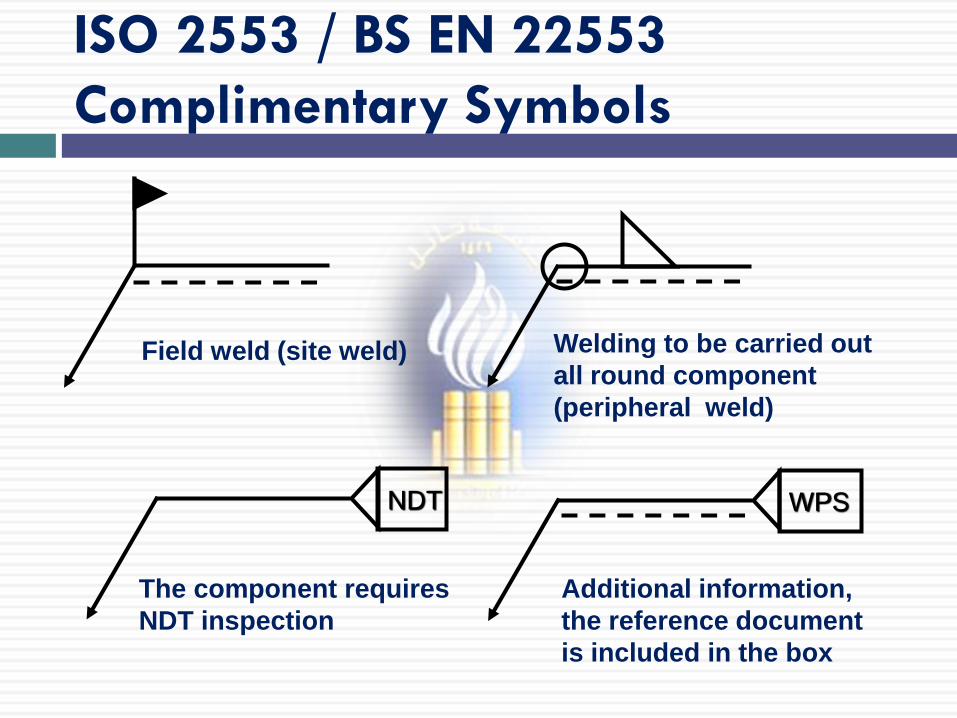
Field weld (site weld)
The component requires
NDT inspection
WPS
Additional information,
the reference document
is included in the box
Welding to be carried out
all round component
(peripheral weld)
ISO 2553 / BS EN 22553
Complimentary Symbols
NDT

44 of 691 Numerical Values for Welding Processes:
111: MMA welding with covered electrode
121: Sub-arc welding with wire electrode
131: MIG welding with inert gas shield
135: MAG welding with non-inert gas shield
136: Flux core arc welding
141: TIG welding
311: Oxy-acetylene welding
72: Electro-slag welding
15: Plasma arc welding
ISO 2553 / BS EN 22553
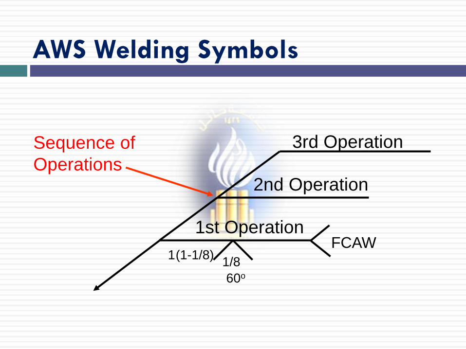
AWS A2.4 Welding Symbols
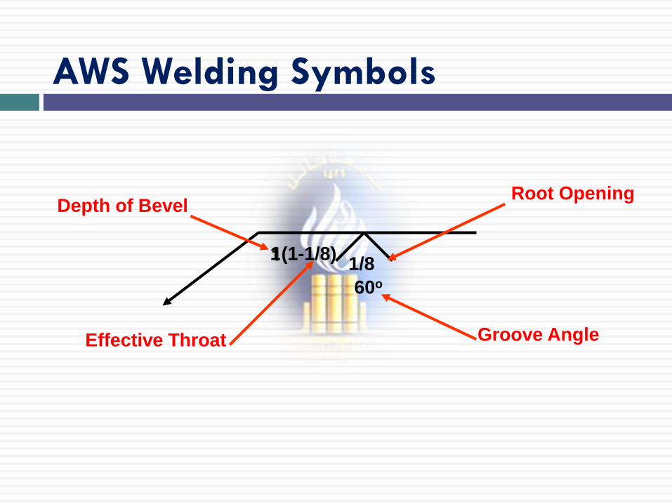
1 (1-1/8)
60o
1/8
Depth of Bevel
Effective Throat
Root Opening
Groove Angle
AWS Welding Symbols
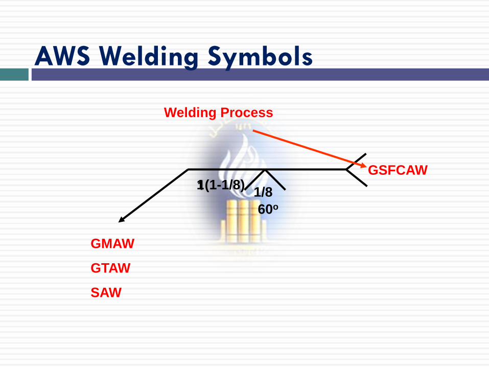
1 (1-1/8)
60o
1/8
GSFCAW
Welding Process
GMAW
GTAW
SAW
AWS Welding Symbols
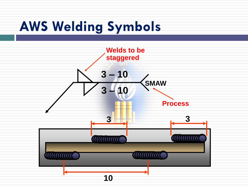
3 – 10
3 – 10
Welds to be staggered
SMAW
Process
10
3 3
AWS Welding Symbols
1 (1-1/8)
60o
1/8
FCAW
Sequence of
Operations
1st Operation
2nd Operation
3rd Operation
AWS Welding Symbols
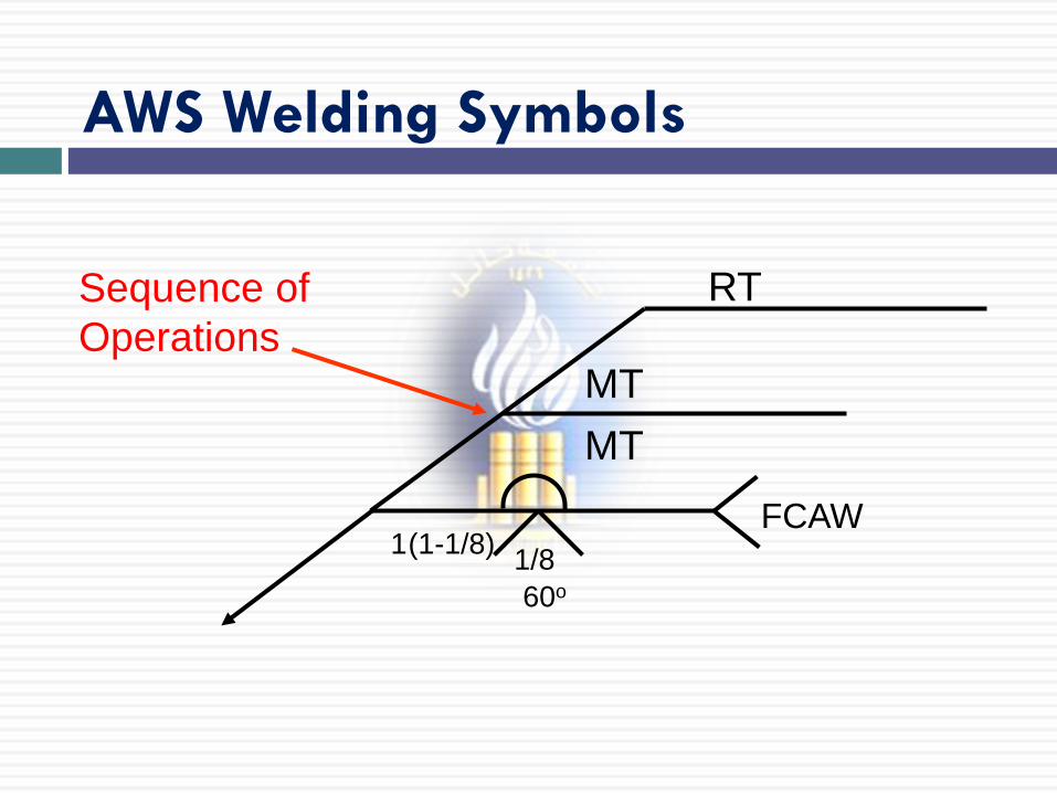
1 (1-1/8)
60o
1/8
FCAW
Sequence of
Operations
RT
MT
MT
AWS Welding Symbols
Fillet Welds and Symbol
Fillet weld triangular-shaped weld placed on the
joint
Fillet weld symbol triangular in shape
Vertical line of fillet weld symbol always drawn to left
of symbol
Size always shown to left of symbol and length to right
of symbol
No length given, then weld should run full length of
joint
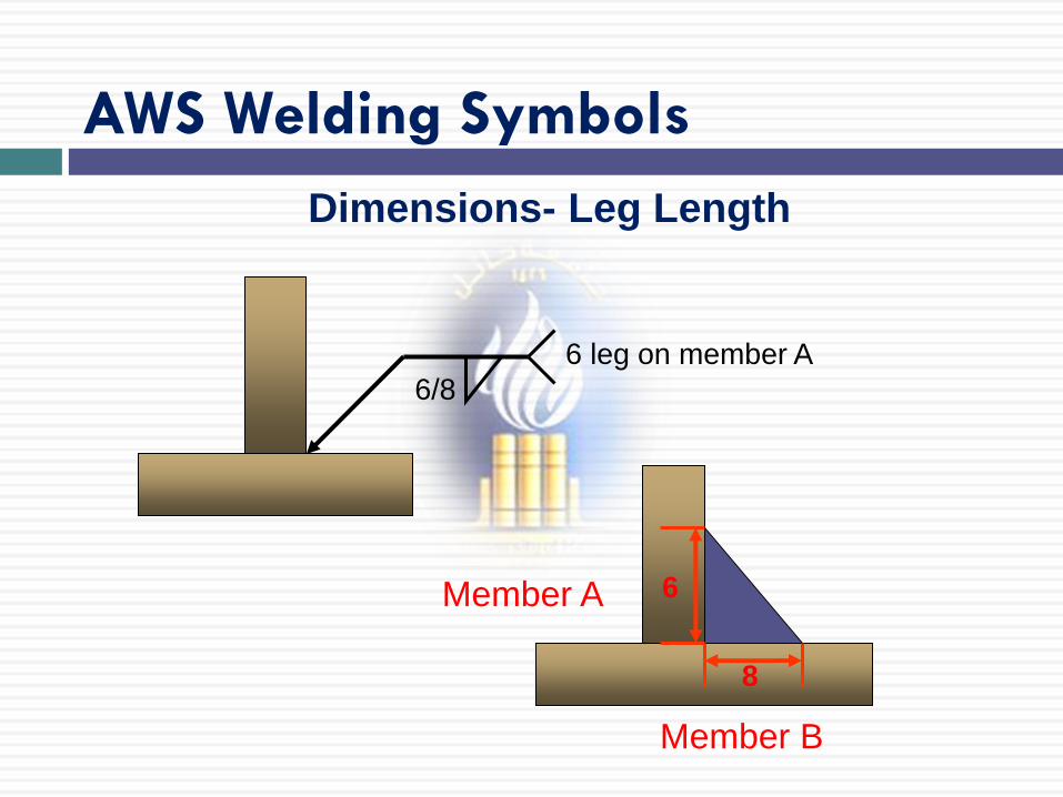
52 of 691 Dimensions- Leg Length
6/8
6 leg on member A
8
6 Member A
Member B
AWS Welding Symbols
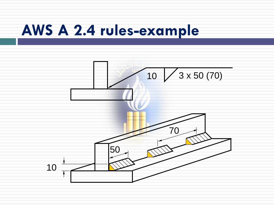
AWS A 2.4 rules-example
10 3 x 50 (70)
10
50
70
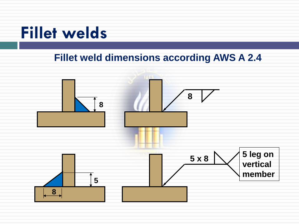
Fillet welds
Fillet weld dimensions according AWS A 2.4
8 8
5
5 x 8
8
5 leg on
vertical
member
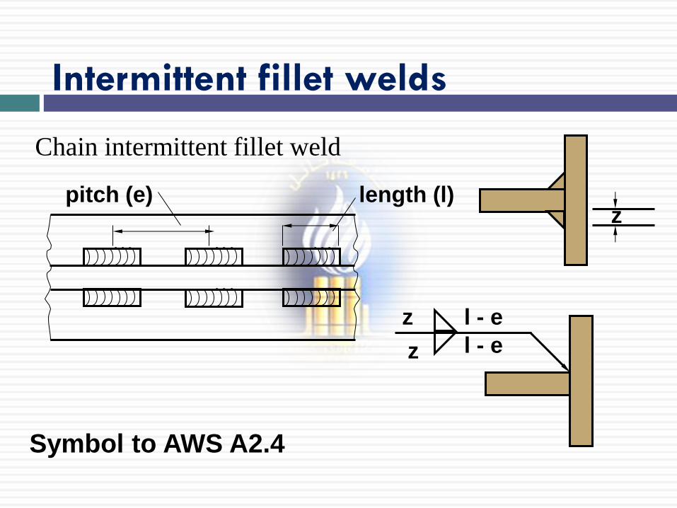
Intermittent fillet welds
Chain intermittent fillet weld
length (l) pitch (e) z
z
l - e z
l - e
Symbol to AWS A2.4
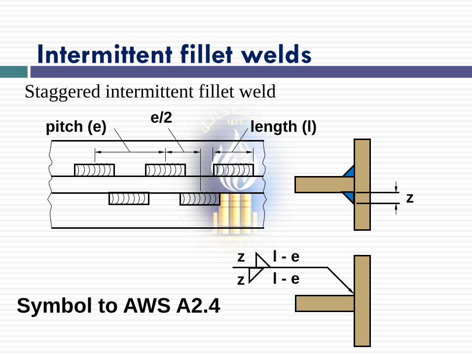
Intermittent fillet welds
Staggered intermittent fillet weld
length (l) pitch (e)
z
z l - e
z l - e
Symbol to AWS A2.4
e/2
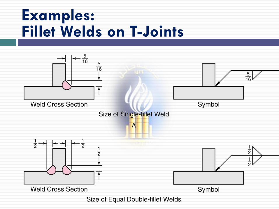
Examples: Fillet Welds on T-Joints
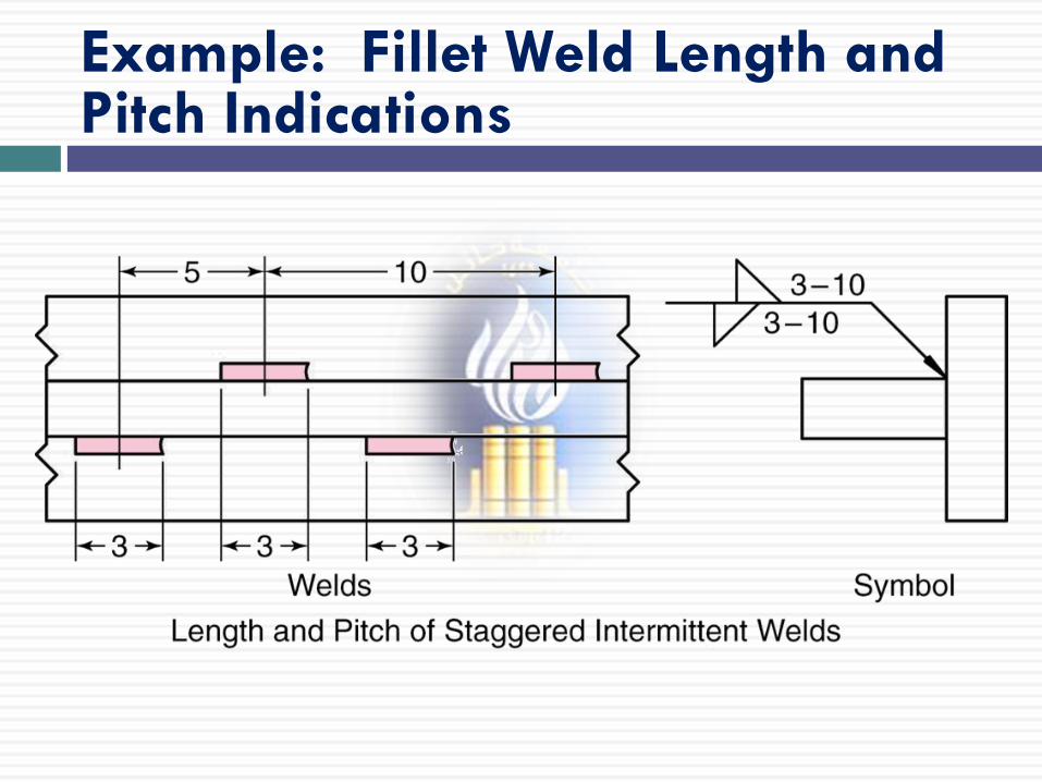
Example: Fillet Weld Length and Pitch Indications
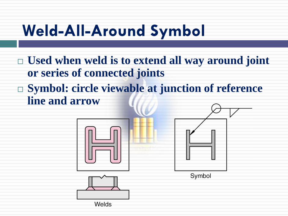
Weld-All-Around Symbol
Used when weld is to extend all way around joint or series of connected joints
Symbol: circle viewable at junction of reference line and arrow
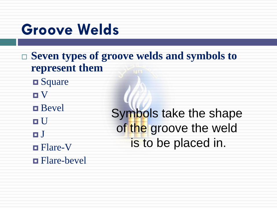
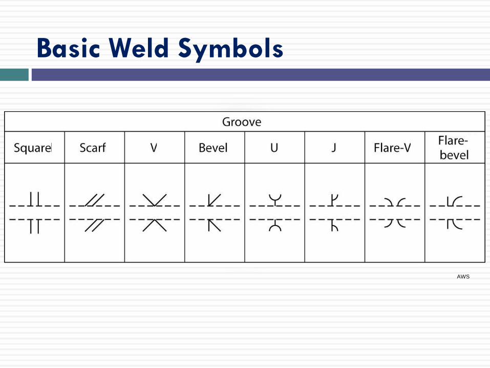
Groove Welds
Seven types of groove welds and symbols to represent them
Square
V
Bevel
U
J
Flare-V
Flare-bevel
Symbols take the shape
of the groove the weld
is to be placed in.
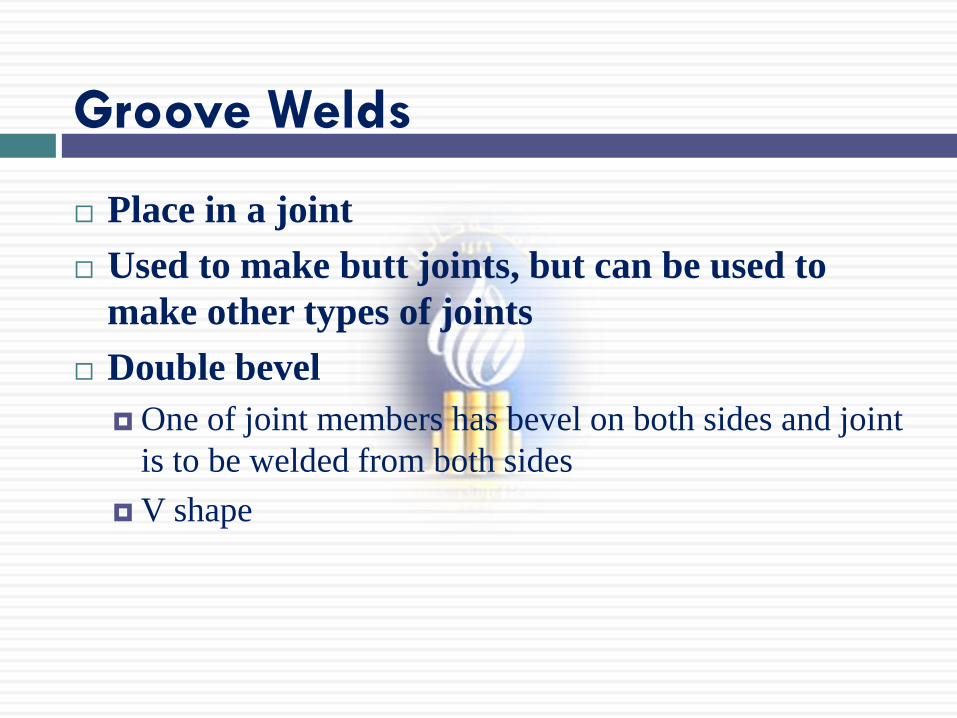
Groove Welds
Place in a joint
Used to make butt joints, but can be used to
make other types of joints
Double bevel
One of joint members has bevel on both sides and joint
is to be welded from both sides
V shape

V-groove Weld on Butt Joint
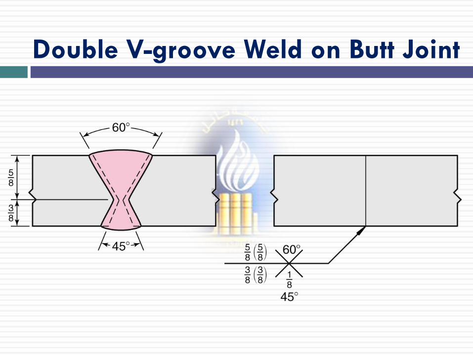
Double V-groove Weld on Butt Joint
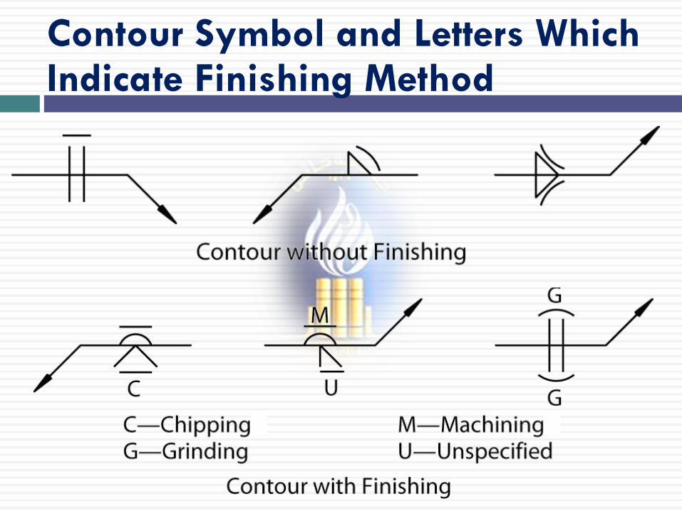
Contour Symbol and Letters Which Indicate Finishing Method