Embed Size (px)
Citation preview
1 | P a g e
Preparation & Characterization of Activated
Kaolinite
Thesis Submitted
By
Siddharth Sekhar Das
(111CR0566)
Under the guidance
Of
Dr. Sunipa Bhattacharyya
In the partial fulfilment of the degree of
Bachelor of Technology
DEPARTMENT OF CERAMIC ENGINEERING
NATIONAL INSTITUTE OF TECHNOLOGY
ROURKELA
3 | P a g e
ACKNOWLEDGEMENT
I would like to thank Dr. Sunipa Bhattacharyya, Department of Ceramic
Engineering, NIT Rourkela, for her enthusiasm, encouragement, and her resolute
dedication to the guidance and support throughout the production of this research
and thesis. My heartfelt thanks to all the faculty members for their suggestions
during this project work. My sincere acknowledgement to the Research Scholars, M.
Tech students and the non-teaching staff for the help and cooperation extended to
us. And finally, my hearty thanks to all my friends who have constantly helped me.
Last but not the least I would like to thank Pallavi Suhasinee Behera, Rupali Singh,
Ipsita Swain, Abhisek Sahoo, Satya Prakash Sahoo, Rajib Lochan Routaray, Arvind
Sir and Bapi Sir for the their support and guidance.
Siddharth Sekhar Das
111CR0566
4 | P a g e
ABSTRACT
Kaolinite has been used for many purposes since ages. Kaolinite is the major mineral
segment of kaolin. The clay sample (china clay) was collected. Calcination of china
clay was carried out at a temperature of 750°C to form metakaolin. The chemical
analysis results of raw clay sample showed that the clay is composed of alumina and
silica. Activated clay was synthesized by acid and alkali leaching process of
metakaolin. Two strong acids HCl and H2SO4 were used for acid activation and KOH
was used for carrying out alkali activation. The residue formed was characterized by
X-Ray Diffraction study to confirm the phases. The particle morphology was studied
by FE-SEM study, and the specific surface area was studied by BET analysis. TG-
DSC analysis was also carried out to see the mass loss and formation of any new
compounds. These analyses were carried out separately for all three samples of
activated clay. The results showed an increase in surface area of the leached clay
which hints that activated clay can be used as a catalytic agent in many chemical
reactions and an adsorber to remove impurities.
5 | P a g e
CONTENTS
SL.NO TOPIC PAGE NO.
1
INTRODUCTION & OBJECTIVE
6-9
2
LITERATURE REVIEW
10-12
3
EXPERIMENTAL METHODS
13-16
4
RESULTS & DISCUSSIONS
17-28
5
CONCLUSION
29-30
6
REFERENCES
31

6 | P a g e
CHAPTER-I
INTRODUCTION & OBJECTIVE
7 | P a g e
1.1 Introduction Since ages kaolin is considered as a major raw material because of its wide usage. One of the
major mineral component of kaolin is kaolinite, which has major impurities like feldspars,
smectites, and illites.The applications of kaolinite are widely used each year in the world for
a various purposes such as ceramics, rubber filler, paper coating, cracking catalysts and
cements. Hydrous aluminium silicate is the major component of kaolin which is of the
composition A12O3.2SiO2.2H2O. As per the structural composition, kaolinite consists of
alumina octahedral sheets and silica tetrahedral sheets which are stacked alternately and has
the theoretical formula Al2Si2O5(OH)4. The theoretical elemental composition is 46.54% SiO2,
39.5% A12O3, and 13.96% H2O. It has a layer lattice structure.
It is also one of the most widely used industrial materials. It is chemically inert over a
varied pH range, has very good covering power and is also white in colour. It is soft and
has a non-abrasive nature. It is very less conducting to heat and electricity. Some uses include,
paper coating, fillers for paints and plastics. It requires many specifications such as particle
size, colour and brightness and viscosity. But other uses require minimum specifications, for
example chemical composition is very much important in case of cement. It can also be used
as a filler and as a coating material on the surface of paper such that the quality of printing
can be improved due to which it is used in paper industries as well.
For the chemical treatment of clays acid activation is a widely used technique. It is because it
has been studied that the chemical treatment of clay sample helps in improving the surface
and also the catalytic properties of the clays. Acid activation consists of the leaching of the
clay with different organic acids, which results in disintegration of clay particles and the
mineral impurities are removed which results in changing the chemical composition and the
structure of the clay as well. The surface area of the particles, number of acid centres and also
8 | P a g e
porosity also increase due to this. The increment is directly related to the intensity of the acid
treatment. [1]
Metakaolinite is the metastable phase that we get from the calcination of kaolinite. It is more
reactive under chemical treatments. The Kaolin was transformed to metakaolin at a
temperature range between 550-950°C by calcination process. This transformation takes place
along with the loss of structural water from the clay material. The solids obtained after that
are strongly influenced by the calcination of kaolin.
For the preparation of porous materials, selective leaching of clay is one of the possible
methods. The term leaching means the use of acids or alkaline solutions which helps in
dissolving the impurities present like Fe, Mg and Al or Si cations. But on the other hand it is
really very difficult to improve the properties of kaolin by these chemical methods, because
the material has got a very high passivity. Even under very strong conditions this is not
significantly affected by any acid or alkaline treatments. Strong conditions imply concentrated
solutions and high temperatures.
There are many benefits of using hydrochloric acid for leaching alumina over any other acids;
as many literatures report. It is because the slurries can be filtered easily, the titanium dioxide
present will not be soluble in HCl and the iron present can be removed easily, which is present
as impurities in many clays. But, it is the severe corrosion of the material that takes place is
the most serious problem with the use of hydrochloric acid. Therefore in order to avoid
corrosion of materials corrosion resistant plastics and rubbers are used.
Many reports have also been found regarding the separation of silica residue from a chloride
solution, where the filtration takes place very fast.
9 | P a g e
1.2 Objective
The prime objective of the work is to prepare activated kaolinite from metakaolins which can
be obtained by the calcination of kaolin. And also to study the behaviour of the sample under
certain acid and alkaline treatments.

10 | P a g e
CHAPTER-II
LITERATURE REVIEW
11 | P a g e
2.1 Belver et al. [1] did a study on the synthesis of the metakaolins which was carried out by the
calcination of kaolin. The calcination was carried out at four different temperatures. The XRD
patterns of the calcined items were studied which indicated various pattern examples. The
pattern of kaolinite disappeared but the pattern of mica remained. Acid activation of the sample
was carried out with HCl of concentration of 6M at room temperature. The temperature was
maintained at 90°C and reflux conditions were provided using a reflux tube. The times of
treatment varied from 6h to 24h. No change in the properties or in the structure or of the
metakaolins were found. The treatment which was done under reflux conditions for 6h helped
in the removal of a large portion of the Al3+ cations which were octahedral in shape, and a
formless silica was also developed.
2.2 Faten Slaty et al. [2] The raw kaolinite is alkali activated with an aqueous solution of sodium
hydroxide. The compressive strength of the sample which was obtained can be influenced by
the properties of the reaction solution. The silica sand content was increased up to 1:1 ratio
w.r.t kaolinite which improves the quality of the solution mixture and the compressive strength
increases due to this factor. This is in fact the major reason for the increment of compressive
strength. The compressive stress is due recorded as 48 mpa under dry conditions and 23 mpa
under wet conditions and the ratio was optimised under curing conditions.
2.3 A.A. Al-Zahrani et al. [3] studied the effects of leaching temperatures required for leaching
and took it from (25oC to boiling temperature), period of activation was in the range of (10-
150 minutes), acid concentration of (1M – 6M). Kaolinite clay was calcined at different
temperatures ranging between 400oC and 800oC at diverse calcination periods of (5 to 120
minutes). The calcined clay was then leached with hydrochloric acid (3M HCl) acid under
some specific leaching conditions. The ideal calcination conditions were found to be around
600oC and 1 hour for calcination temperature and time period respectively.
2.4 C.Bazin et.al [4] studied about the recovery of alumina from Kaolin. It was observed that in
case of sulphuric acid or hydrochloric acid leaching process the amount of alumina was
12 | P a g e
extracted by 10 percent and this process can be exactly used for calcined clay. The
aluminium present in the calcined clay was leached by using sulphuric acid (at 100–120 °C
temperature). Silica as a deposited and considered as residue which was insoluble in the
process of leaching. The residue was separated from the aluminium chloride solution by using
fluid separation technique. The highest amount of alumina was extracted by a hydrochloric
acid leached process rather than the of sulphuric acid leached method .For calcined clay the
percentage of extraction was observed to be more.
2.5 K. Okado et al. [5] studied that the acid treatment of clay reduces the Al2O3 content and
increases the SiO2 substance. Composition changes very rapidly in the early stages of leaching
of the sample. However, after about a time span of 1.5 hours the rate decrease step by step..
Impurities present like Fe2O3 and K2O are removed by leaching from 0.3 to 0.1 mass
percentage yet the TiO2 content increased from 2.0 to 3.8 mass percentage. The sum of
the remaining SO4 in the H2SO4 treated tests found was about 0.3 mass percent even after
the last washing was done.
2.6 Temuujin et al. [6] researched XRD examples of the unground and ground kaolinite, and of
ground samples which was leached for varying times. The little measure of impurity mica and
quartz distinguished in the XRD originates from the first kaolinite. After grinding, all the
kaolinite peaks vanished. Leached metakaolinite shows micro pores but no macrospores or
mesopores in the structure.
2.7 Y. Abdullahi et al. [7] investigated about the process regarding leaching of silica. The silica
residue was obtained from kaolinitic clay after the treatment through acid. The main objective
was to prepare different concentration of silica from calcined clay or kaolinite. The calcined
clay was also leached with a sodium hydroxide solution. The kaolinite was calcined and
transformed to metakaolinite at 1000°C for 1 hour which can activate the silica content in the
kaolinite. The amount of silica which was extracted from the Kaolinite was soluble in a
medium using 5, 10, 20, 30, and 40% w/w NaOH..
13 | P a g e
CHAPTER-III
EXPERIMENTAL METHOD
14 | P a g e
3.1 Experimental
Initially raw china clay was taken and was characterised by XRD, BET and TG-DSC to study the
phases present and measure the surface area of the raw clay. Then it was calcined at a temperature
of 7500C. Calcination helped in the conversion of the material to metakaolin.
Two types of Chemical Activations were carried out i.e.
1. Acid Leaching
2. Alkali Leaching
The Kaolin or Clay was used as a starting material. The chemical composition of kaolin is given
in Table 1.
The clay sample was ground in an agate mortar to decrease the particle sizes, particles below 0.5
mm in size. Powdered kaolin was calcined at a temperature of 750 ˚C for a time period of 2 h to
form metakaolin in an electric furnace to loosen the alumina components. Then the metakaolin
undergoes various leaching process listed below:
1. Leaching of Clay by 6M HCl
2. Leaching of Clay by 6M H2SO4
3. Leaching of Clay by 6M KOH
3.2 Leaching process
The powder sample of kaolin was dispersed in an acid/alkali solution to attaining a solid/liquid
ratio of 1:20 by weight. The mixture of kaolin powder and acid/alkali was taken in a 500 mL round
bottom flask. The reaction flask was fitted with a reflux condenser and the mixture was stirred
with the magnetic stirrer for 6h. The temperature of the mixture was set at 70˚C. After the mixture
of kaolin and acid/alkali had been leached, it was cooled to room temperature and filtered to
15 | P a g e
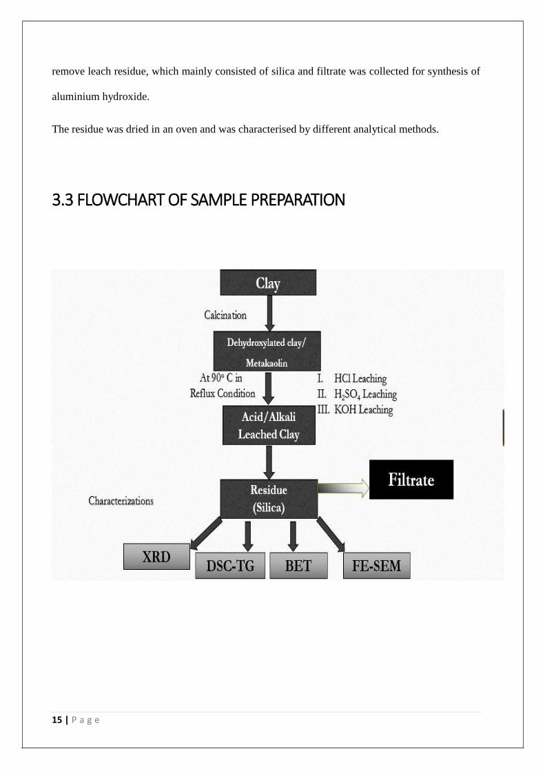
remove leach residue, which mainly consisted of silica and filtrate was collected for synthesis of
aluminium hydroxide.
The residue was dried in an oven and was characterised by different analytical methods.
3.3 FLOWCHART OF SAMPLE PREPARATION
16 | P a g e
3.4 TG-DSC Analysis
The Differential Scanning Calorimetry is generally used to study the reaction nature and change
of mass which occur during the firing stages of the sample. The measurement or heat treatment
was done up to 1200oC at a rate of 10oC/min. Argon atmosphere was maintained during the
analysis.
3.5 Phase Identification (XRD Analysis)
X- Ray Diffraction study was used to find the different phases and crystallography of the elements
present in the sample. For this, the samples were calcined and crushed into fine powder. The
scanning range was maintained at 20oC with a step size of 0.05o. The data which was obtained
was analysed with the Philips X- Pert High Score software and the peaks were identified.
3.6 Microstructure Analysis (FE-SEM)
The microstructure were analysed using Field Emission Scanning Electron Microscope (Nova
Nano SEM/ FEI 450). The powder samples were used for taking the microstructures. Particle size,
particle morphology were studied.
3.7 BET Analysis
BET plots were analysed which gives an exact specific surface area of materials by nitrogen adsorption
measured as a component of relative weight. Which utilizes a completely computerized analyser. The
technique measures surface area and pore size which are evaluated to determine the total specific surface
area in m2/g which provides important information about the effects of surface porosity and particle size in
many applications. This was done to know the specific surface area.

17 | P a g e
CHAPTER-IV
RESULTS & DISCUSSIONS
18 | P a g e
4.1 Raw material analysis
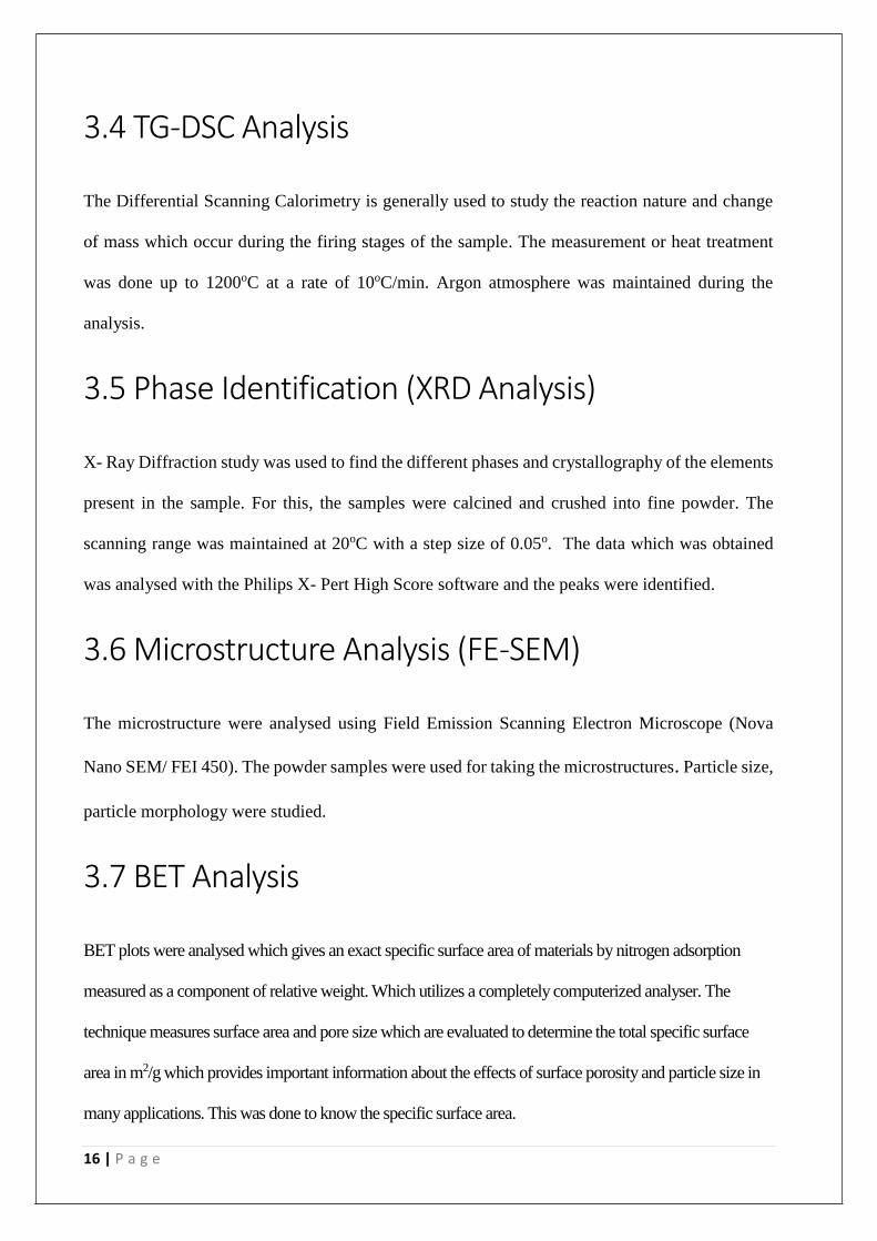
4.1.1 Chemical analysis of Raw China Clay
COMPOUND WEIGHT PERCENTAGE
SiO2 49.53
Al2O3 29.50
Fe2O3 2.15
CaO 2.25
MgO 0.753
Loss on Ignition 14.09
Table-1
Raw china clay was taken and chemically analysed for determining the amount of different
constituents present in it. It was found that clay sample contains SiO2 and Al2O3 as two major
constituents and Fe2O3, CaO, and MgO as impurities. The detail results were tabulated as table-1.
19 | P a g e
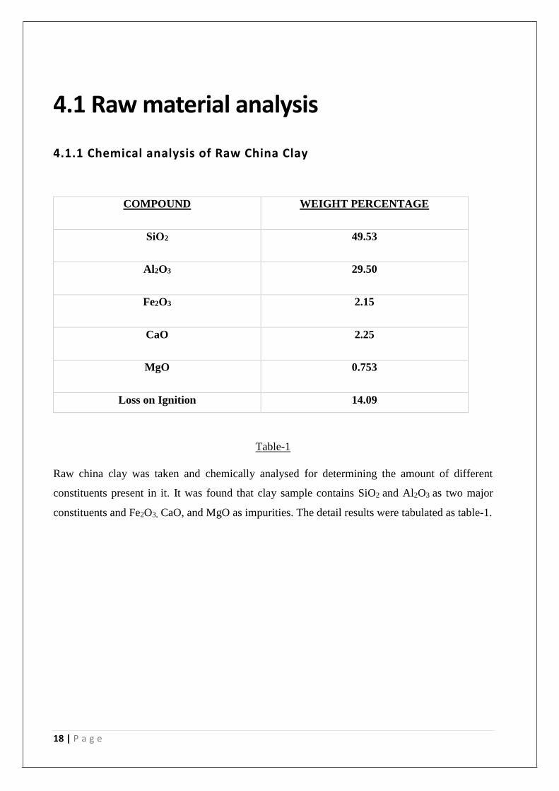
4.1.2 TG-DSC analysis of raw china clay
0 200 400 600 800 1000 1200
84
86
88
90
92
94
96
98
100
102
MA
SS
(%
)
D
Fig-1 Thermogravimetric analysis of raw clay
Figure-1 shows the thermogravimetric study of clay sample. The graph indicates the loss of
primary water at a temperature of about 200oC and the loss of hydroxyl groups or the removal of
secondary water at a temperature of about 600 oC.
Fig-2 DSC of raw clay.
The DSC graph (Figure-2) of the raw china clay indicates the formation of two peaks one
endothermic and another exothermic peak. The endothermic peak around 580 oC indicates
dehydroxylation. The exothermic peak is because of the formation of a spinel phase or gamma-
alumina phase.
0 200 400 600 800 1000 1200
-0.5
0.0
0.5
1.0
1.5
2.0
2.5
3.0
3.5
DS
C
(mW
/mg
)
TEMPERATURE(oC)
20 | P a g e
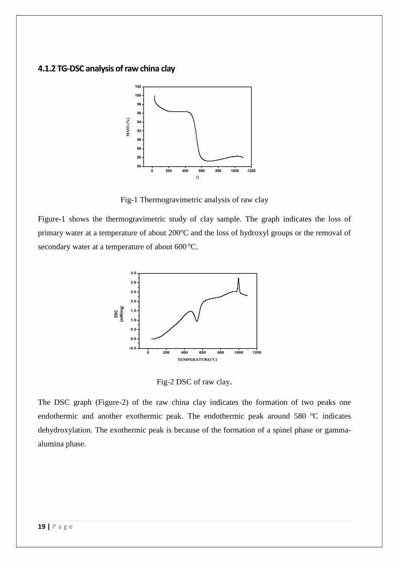
4.1.3 Specific Surface Area of Raw clay
Fig-3 BET plot of raw clay.
The specific surface area of the raw china clay was found out using the BET method. And the
surface area of the raw china clay was found 17 m2/gm.
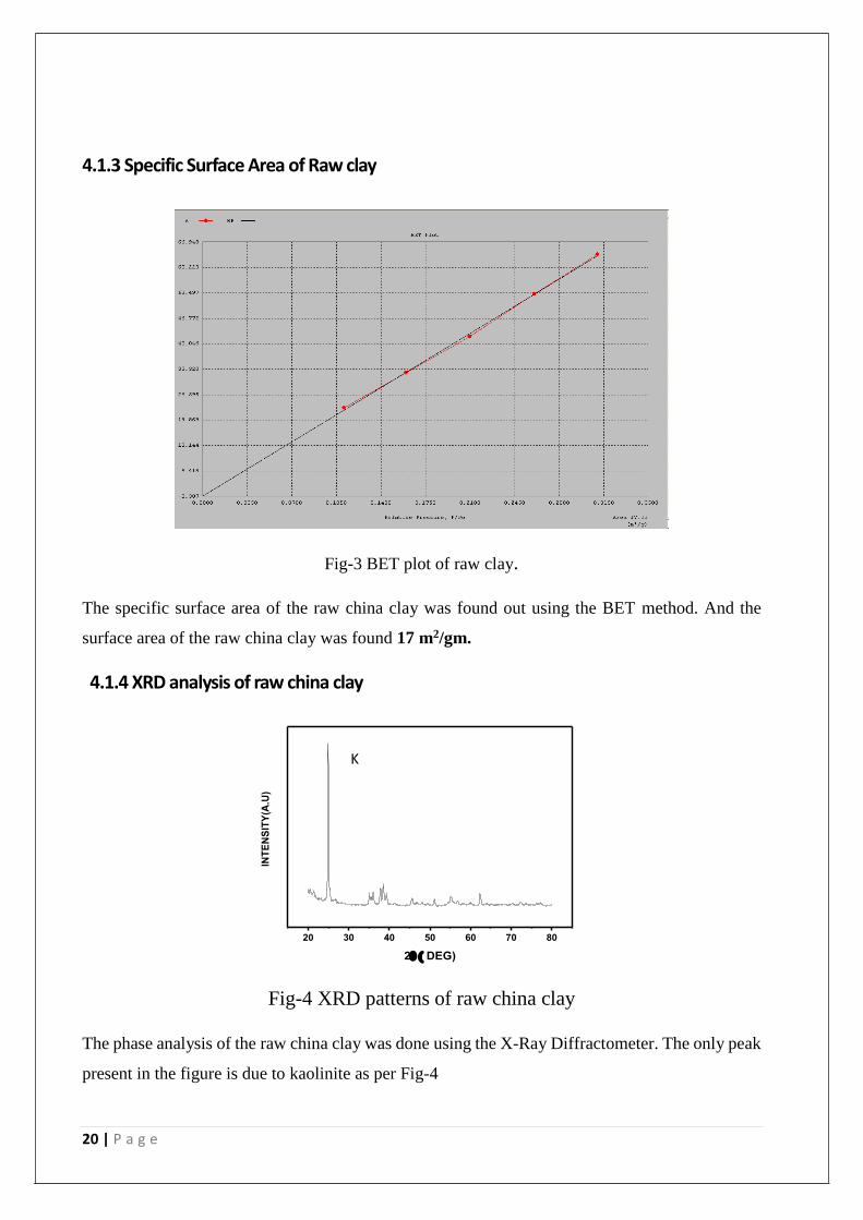
4.1.4 XRD analysis of raw china clay
Fig-4 XRD patterns of raw china clay
The phase analysis of the raw china clay was done using the X-Ray Diffractometer. The only peak
present in the figure is due to kaolinite as per Fig-4
20 30 40 50 60 70 80
INT
EN
SIT
Y(A
.U)
2 DEG)
SkK
KK
KK
K
K
21 | P a g e
4.2 CALCINED CLAY
4.2.1 TG-DSC analysis of calcined clay
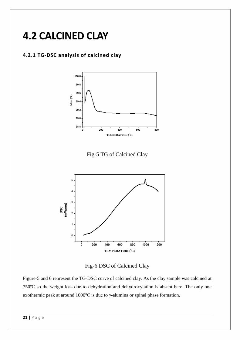
Fig-5 TG of Calcined Clay
0 200 400 600 800 1000 1200
0
1
2
3
4
5
DS
C
(mW
/mg
)
TEMPERATURE(oC)
Fig-6 DSC of Calcined Clay
Figure-5 and 6 represent the TG-DSC curve of calcined clay. As the clay sample was calcined at
750oC so the weight loss due to dehydration and dehydroxylation is absent here. The only one
exothermic peak at around 1000oC is due to γ-alumina or spinel phase formation.
0 200 400 600 800
98.8
99.0
99.2
99.4
99.6
99.8
100.0
Mass
(%
)
TEMPERATURE (oC)
22 | P a g e
4.3 ACID LEACHED CLAY
4.3.1 HCL LEACHING
4.3.1.1 CHEMICAL ANALYSIS
Amount of silica in HCl leached clay - 82.53 %
By the help of chemical analysis technique we find the percentage of silica present in the clay
leached by HCl, and it was found to be 82.53 % which proves that the major component of the
leached clay is silica.
4.3.1.2 TG-DSC analysis of HCl leached clay
0 200 400 600 800 1000 1200
80
85
90
95
100
MA
SS
(%)
TEMPERATURE(oC)
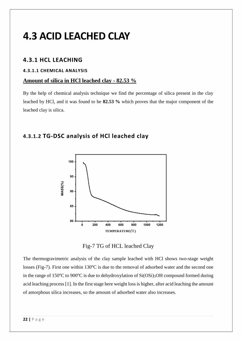
Fig-7 TG of HCL leached Clay
The thermogravimetric analysis of the clay sample leached with HCl shows two-stage weight
losses (Fig-7). First one within 130oC is due to the removal of adsorbed water and the second one
in the range of 150oC to 900oC is due to dehydroxylation of Si(OSi)3OH compound formed during
acid leaching process [1]. In the first stage here weight loss is higher, after acid leaching the amount
of amorphous silica increases, so the amount of adsorbed water also increases.
23 | P a g e
0 200 400 600 800 1000 1200
-1
0
1
2
3
4
5
6
7
8
DS
C
(mW
/mg
)
TEMPERATURE(oC)
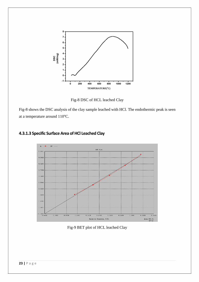
Fig-8 DSC of HCL leached Clay
Fig-8 shows the DSC analysis of the clay sample leached with HCl. The endothermic peak is seen
at a temperature around 110oC.
4.3.1.3 Specific Surface Area of HCl Leached Clay
Fig-9 BET plot of HCL leached Clay
24 | P a g e
The specific surface area of the HCl leached clay was found out using the BET technique, and the
surface area was measured 203.9 m2/gm. The surface area of the sample has increased markedly
compared to the raw clay sample.
4.3.1.4 XRD analysis of HCl Leached Clay
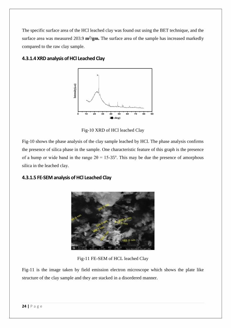
Fig-10 XRD of HCl leached Clay
Fig-10 shows the phase analysis of the clay sample leached by HCl. The phase analysis confirms
the presence of silica phase in the sample. One characteristic feature of this graph is the presence
of a hump or wide band in the range 2θ = 15-35o. This may be due the presence of amorphous
silica in the leached clay.
4.3.1.5 FE-SEM analysis of HCl Leached Clay
Fig-11 FE-SEM of HCL leached Clay
Fig-11 is the image taken by field emission electron microscope which shows the plate like
structure of the clay sample and they are stacked in a disordered manner.
0 10 20 30 40 50 60 70 80 90
Inte
nsit
y(a.
u)
2deg)
s
25 | P a g e
4.3.2 H2SO4 LEACHING
4.3.2.1 CHEMICAL ANALYSIS
Amount of silica in H2SO4 leached clay - 83.73%
By the help of chemical analysis technique we find the percentage of silica present in the clay
leached by H2SO4, and it was found to be 83.73 % which proves that the major component of the
leached clay is silica.
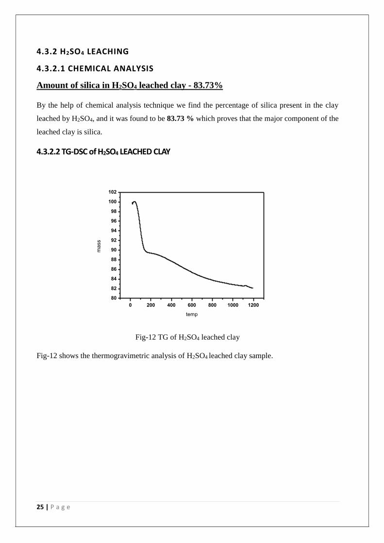
4.3.2.2 TG-DSC of H2SO4 LEACHED CLAY
0 200 400 600 800 1000 1200
80
82
84
86
88
90
92
94
96
98
100
102
mass
temp
Fig-12 TG of H2SO4 leached clay
Fig-12 shows the thermogravimetric analysis of H2SO4 leached clay sample.
26 | P a g e
0 200 400 600 800 1000 1200
-1
0
1
2
3
4
5
6
7
DS
C
(mW
/mg
)
TEMPERATURE(oC)
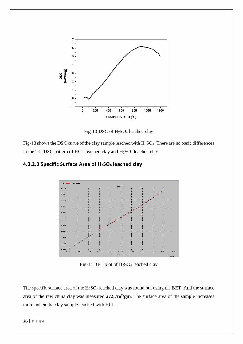
Fig-13 DSC of H2SO4 leached clay
Fig-13 shows the DSC curve of the clay sample leached with H2SO4. There are no basic differences
in the TG-DSC pattern of HCL leached clay and H2SO4 leached clay.
4.3.2.3 Specific Surface Area of H2SO4 leached clay
Fig-14 BET plot of H2SO4 leached clay
The specific surface area of the H2SO4 leached clay was found out using the BET. And the surface
area of the raw china clay was measured 272.7m2/gm. The surface area of the sample increases
more when the clay sample leached with HCl.
27 | P a g e
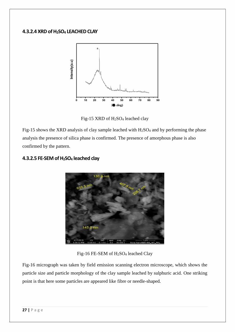
4.3.2.4 XRD of H2SO4 LEACHED CLAY
Fig-15 XRD of H2SO4 leached clay
Fig-15 shows the XRD analysis of clay sample leached with H2SO4 and by performing the phase
analysis the presence of silica phase is confirmed. The presence of amorphous phase is also
confirmed by the pattern.
4.3.2.5 FE-SEM of H2SO4 leached clay
Fig-16 FE-SEM of H2SO4 leached Clay
Fig-16 micrograph was taken by field emission scanning electron microscope, which shows the
particle size and particle morphology of the clay sample leached by sulphuric acid. One striking
point is that here some particles are appeared like fibre or needle-shaped.
0 10 20 30 40 50 60 70 80 90
Inte
ns
ity
(a.u
)
2deg)
s
28 | P a g e
4.4 ALKALI LEACHING 4.4.1KOH LEACHED CLAY
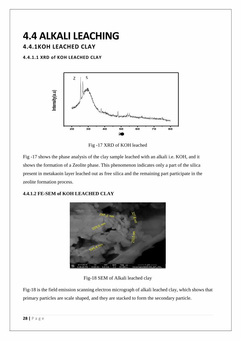
4.4.1.1 XRD of KOH LEACHED CLAY
Fig -17 XRD of KOH leached
Fig -17 shows the phase analysis of the clay sample leached with an alkali i.e. KOH, and it
shows the formation of a Zeolite phase. This phenomenon indicates only a part of the silica
present in metakaoin layer leached out as free silica and the remaining part participate in the
zeolite formation process.
4.4.1.2 FE-SEM of KOH LEACHED CLAY
Fig-18 SEM of Alkali leached clay
Fig-18 is the field emission scanning electron micrograph of alkali leached clay, which shows that
primary particles are scale shaped, and they are stacked to form the secondary particle.
20 30 40 50 60 70 80
Inte
nsity
(a.u
)
2
QZ S

29 | P a g e
CHAPTER-V
CONCLUSION & FUTURE WORK
30 | P a g e
5.1 Conclusion
Acid activated and Alkali activated clay were prepared. All the characteristic analyses were carried
out and the results were compared. It is seen that the alumina phase disappears on acid activation
of clay sample. Amorphous phase along with silica are present in acid leached clay whereas zeolite
phase is formed after alkali activation of clay. It is also seen that the surface area of the clay
increases on activation which proves the effectively of this activated clay for the catalytic
application.
5.2 Future Work
There is also a plan for the modification of the preparation routes to get better activity and
properties of the material.
31 | P a g e
REFERENCES
1. Belver C, Miguel A B Munoz , and M A Vicente; Chemical Activation of a Kaolinite under
Acid and Alkaline Conditions; Chem. Mater, 2002, VOL-14 (5), pp 2033–2043.
2. Slaty Faten, H Khoury, J Wastiels b, Hubert R; Characterization of alkali activated kaolinitic
clay; Applied Clay Science (2013).
3. Al-Zahrani AA and M.H. A Majid; Extraction of Alumina from Local Clays by Hydrochloric
Acid Process; JKAU: Eng. Sci., Vol. 20 No.2, and pp: 29-41.
4. Bazin C, K. El-Ouassiti a, V. Ouellet b; Sequential leaching for the recovery of alumina from
a Canadian clay; Hydrometallurgy 88 (2007) pp-196–201
5. OKADA .K; Preparation of Porous Silica from Mechanically Activated Kaolinite; Journal of
Porous Materials 8: 233–238, 2001.
6. TEMUUJIN J, G. BURMAA, J. AMGALAN; Preparation of Porous Silica from Mechanically
Activated Kaolinite; Journal of Porous Materials; Journal of Porous Materials 8: 233–238,
2001
7. A Y Roast-Alkaline Leaching of silica from kaolinitic clay; VOL. 8, NO. 10, October 2013
ARPN Journal of Engineering and Applied Sciences.