Embed Size (px)
DESCRIPTION
Â
Citation preview
Industry
Premier spherical roller bearings: our vast experience
All you need to knowabout SNR Premier spherical roller bearings
SummaryPremier: more than a product range - a leading manufacturer's philosophy 2-3
Performance and sizes available 4-5
Materials and treatments 6-7
Design, tests and manufacturing means 8-9
Cages 10-13
Lubrication 14-15
Speeds 16-17
Technical information: fundamentals 18-21
Designations, suffixes 22
Range 23-27
Sleeves 28-33
Maintenance
- Installation - Removal 34
- Lubrication 35
- Monitoring, Services 36-37
Summary
1
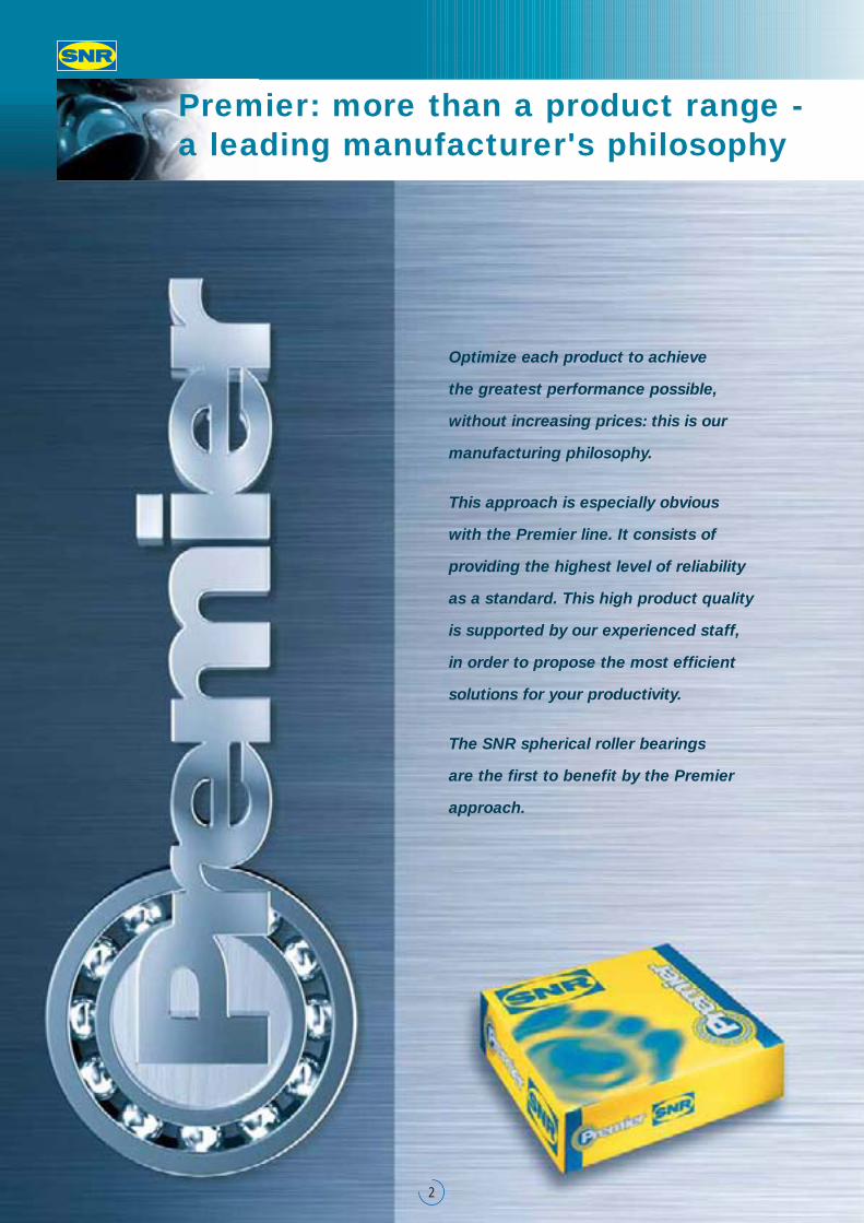
Optimize each product to achieve
the greatest performance possible,
without increasing prices: this is our
manufacturing philosophy.
This approach is especially obvious
with the Premier line. It consists of
providing the highest level of reliability
as a standard. This high product quality
is supported by our experienced staff,
in order to propose the most efficient
solutions for your productivity.
The SNR spherical roller bearings
are the first to benefit by the Premier
approach.
Premier: more than a product range - a leading manufacturer's philosophy
2
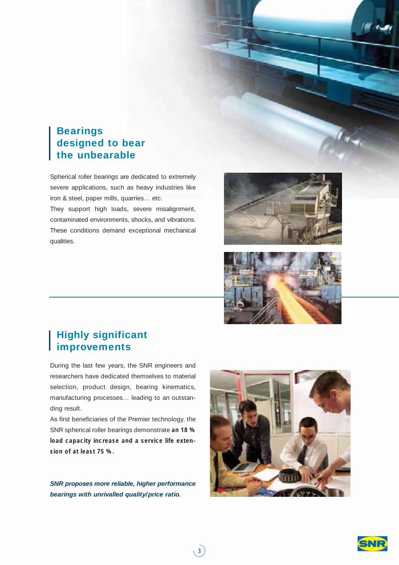
Spherical roller bearings are dedicated to extremely
severe applications, such as heavy industries like
iron & steel, paper mills, quarries… etc.
They support high loads, severe misalignment,
contaminated environments, shocks, and vibrations.
These conditions demand exceptional mechanical
qualities.
Bearings designed to bear the unbearable
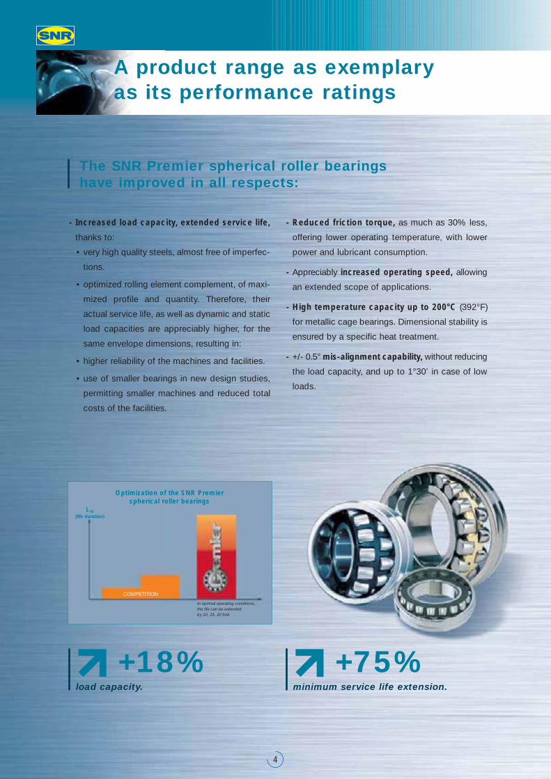
During the last few years, the SNR engineers and
researchers have dedicated themselves to material
selection, product design, bearing kinematics,
manufacturing processes… leading to an outstan-
ding result.
As first beneficiaries of the Premier technology, the
SNR spherical roller bearings demonstrate an 18 %
load capacity increase and a service life exten-
sion of at least 75 %.
SNR proposes more reliable, higher performance
bearings with unrivalled quality/price ratio.
Highly significant improvements
3
A product range as exemplary as its performance ratings
4
- Increased load capacity, extended service life,
thanks to:
• very high quality steels, almost free of imperfec-
tions.
• optimized rolling element complement, of maxi-
mized profile and quantity. Therefore, their
actual service life, as well as dynamic and static
load capacities are appreciably higher, for the
same envelope dimensions, resulting in:
• higher reliability of the machines and facilities.
• use of smaller bearings in new design studies,
permitting smaller machines and reduced total
costs of the facilities.
- Reduced friction torque, as much as 30% less,
offering lower operating temperature, with lower
power and lubricant consumption.
- Appreciably increased operating speed, allowing
an extended scope of applications.
- High temperature capacity up to 200°C (392°F)
for metallic cage bearings. Dimensional stability is
ensured by a specific heat treatment.
- +/- 0.5° mis-alignment capability, without reducing
the load capacity, and up to 1°30’ in case of low
loads.
The SNR Premier spherical roller bearings have improved in all respects:
load capacity.
+18%minimum service life extension.
+75%
L10(life duration)
COMPETITION
In optimal operating conditions, the life can be extended by 10, 15, 20 fold
Optimization of the SNR Premier spherical roller bearings
5
Diversified conditions, tailor-made solutions
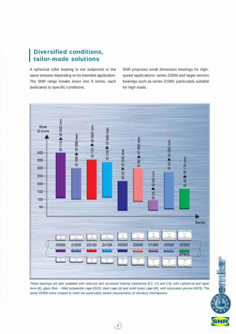
These bearings are also available with reduced and increased internal clearances (C2, C3 and C4), with cylindrical and taper
bore (K), glass fiber – filled polyamide cage (G15), steel cage (A) and solid brass cage (M), with lubrication groove (W33). The
series EF800 were created to meet the particularly severe requirements of vibratory mechanisms.
A spherical roller bearing is not subjected to the
same stresses depending on its intended application.
The SNR range breaks down into 9 series, each
dedicated to specific conditions.
SNR proposes small dimension bearings for high-
speed applications: series 23000 and larger section
bearings such as series 22300, particularly suitable
for high loads.
Cast quality, alloy purity
To sustain extreme stress loads, spherical roller
bearings require a steel quality beyond reproach.
Two main considerations: strictly observed casting
process and inclusion cleanliness. The SNR steel
suppliers are selected worldwide, in line with these
two criteria. The corporate agreements implemen-
ted with them guarantees reliable availability and
perfect traceability.
While continuously improving measurement accu-
racy, SNR has maintained the same test principles
for thirty-five years! These constant principles are
valuable, having allowed us to assess and control
the evolution of the steels for several decades.
Service life is almost doubled
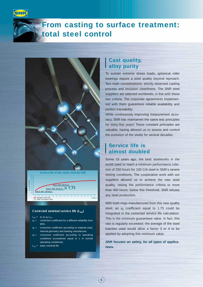
Some 15 years ago, the best steelworks in the
world used to reach a minimum performance crite-
rion of 250 hours for 100 Cr6 steel in SNR's severe
testing conditions. The cooperative work with our
suppliers allowed us to achieve the new steel
quality, raising the performance criteria to more
than 450 hours: below this threshold, SNR refuses
any steel production.
With both rings manufactured from this new quality
steel, an a2 coefficient equal to 1.75 could be
integrated in the corrected service life calculation.
This is the minimum guaranteed value. In fact, this
rate is regularly exceeded: the average of the steel
batches used would allow a factor 3 or 4 to be
applied by adopting this minimum value.
SNR focuses on safety, for all types of applica-
tions.
From casting to surface treatment: total steel control
Corrected nominal service life (Lna)
Lna = a1.a2.a3.L10
a1 = correction coefficient for a different reliability from
90%.
a2 = correction coefficient according to material used,
internal geometry and bearing manufacture.
a3 = correction coefficient according to operating
conditions (considered equal to 1 in normal
operating conditions).
L10 = basic nominal life.
6
Years
Before 1991: 100 hours
880
100
200
300
400
500
600
700
800
900
1 000
89 90 91 92 93 94 95 96 97 98 99 00 01 02 03 04 05
Before 1993: 250 hours
Since 1993: 450 hours
Average service life
in h
ou
rs
SNR's acceptance limit
x 1,75
Service life of the steels used by SNR
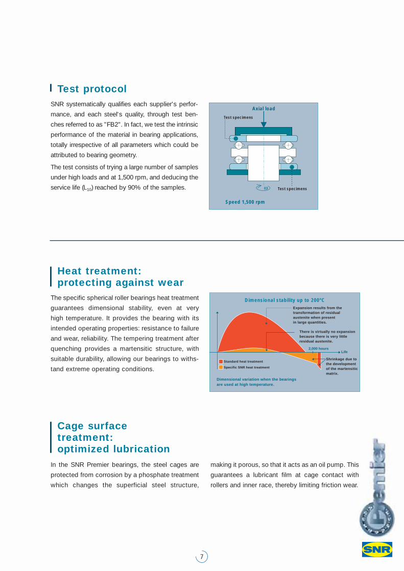
Test protocol SNR systematically qualifies each supplier's perfor-
mance, and each steel's quality, through test ben-
ches referred to as "FB2". In fact, we test the intrinsic
performance of the material in bearing applications,
totally irrespective of all parameters which could be
attributed to bearing geometry.
The test consists of trying a large number of samples
under high loads and at 1,500 rpm, and deducing the
service life (L10) reached by 90% of the samples.
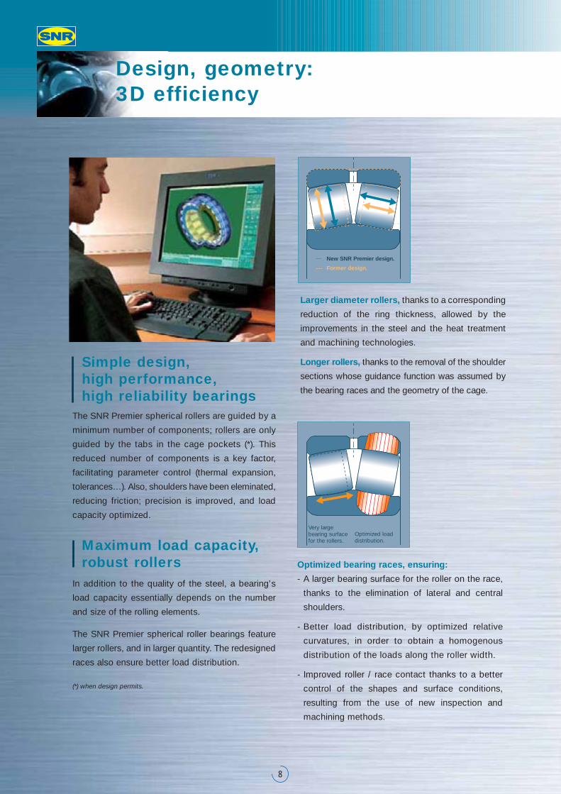
Heat treatment: protecting against wear
The specific spherical roller bearings heat treatment
guarantees dimensional stability, even at very
high temperature. It provides the bearing with its
intended operating properties: resistance to failure
and wear, reliability. The tempering treatment after
quenching provides a martensitic structure, with
suitable durability, allowing our bearings to withs-
tand extreme operating conditions.
7
Cage surface treatment: optimized lubrication
In the SNR Premier bearings, the steel cages are
protected from corrosion by a phosphate treatment
which changes the superficial steel structure,
making it porous, so that it acts as an oil pump. This
guarantees a lubricant film at cage contact with
rollers and inner race, thereby limiting friction wear.
Test specimens
Axial load
Speed 1,500 rpm
Test specimens
Life
Expansion results from the�transformation of residual�austenite when present�in large quantities.
There is virtually no expansion�because there is very little�residual austenite.
Shrinkage due to�the development�of the martensitic�matrix.
2,000 hours
Standard heat treatment
Dimensional variation when the bearings�are used at high temperature.
Specific SNR heat treatment
Dimensional stability up to 200°C
Simple design, high performance, high reliability bearings
The SNR Premier spherical rollers are guided by a
minimum number of components; rollers are only
guided by the tabs in the cage pockets (*). This
reduced number of components is a key factor,
facilitating parameter control (thermal expansion,
tolerances…). Also, shoulders have been eleminated,
reducing friction; precision is improved, and load
capacity optimized.
Maximum load capacity,robust rollers
In addition to the quality of the steel, a bearing's
load capacity essentially depends on the number
and size of the rolling elements.
The SNR Premier spherical roller bearings feature
larger rollers, and in larger quantity. The redesigned
races also ensure better load distribution.
(*) when design permits.
Design, geometry: 3D efficiency
8
__ New SNR Premier design.
--- Former design.
Larger diameter rollers, thanks to a corresponding
reduction of the ring thickness, allowed by the
improvements in the steel and the heat treatment
and machining technologies.
Longer rollers, thanks to the removal of the shoulder
sections whose guidance function was assumed by
the bearing races and the geometry of the cage.
Optimized bearing races, ensuring:
- A larger bearing surface for the roller on the race,
thanks to the elimination of lateral and central
shoulders.
- Better load distribution, by optimized relative
curvatures, in order to obtain a homogenous
distribution of the loads along the roller width.
- Improved roller / race contact thanks to a better
control of the shapes and surface conditions,
resulting from the use of new inspection and
machining methods.
Very large bearing surfacefor the rollers.
Optimized loaddistribution.
9
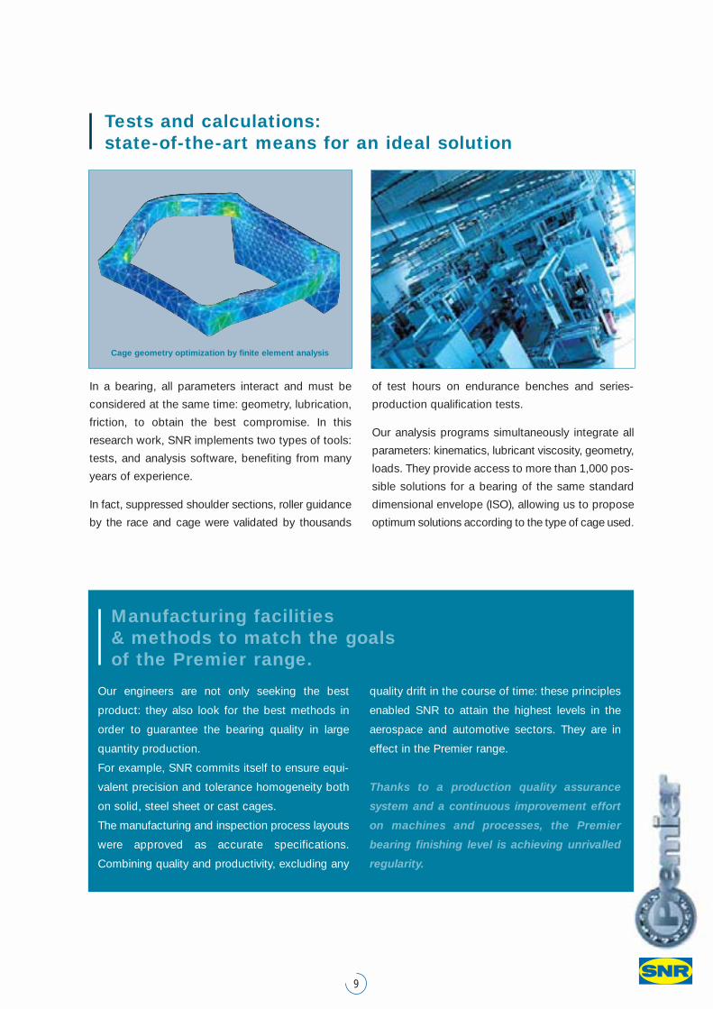
In a bearing, all parameters interact and must be
considered at the same time: geometry, lubrication,
friction, to obtain the best compromise. In this
research work, SNR implements two types of tools:
tests, and analysis software, benefiting from many
years of experience.
In fact, suppressed shoulder sections, roller guidance
by the race and cage were validated by thousands
of test hours on endurance benches and series-
production qualification tests.
Our analysis programs simultaneously integrate all
parameters: kinematics, lubricant viscosity, geometry,
loads. They provide access to more than 1,000 pos-
sible solutions for a bearing of the same standard
dimensional envelope (ISO), allowing us to propose
optimum solutions according to the type of cage used.
Tests and calculations: state-of-the-art means for an ideal solution
Manufacturing facilities & methods to match the goals of the Premier range.
Our engineers are not only seeking the best
product: they also look for the best methods in
order to guarantee the bearing quality in large
quantity production.
For example, SNR commits itself to ensure equi-
valent precision and tolerance homogeneity both
on solid, steel sheet or cast cages.
The manufacturing and inspection process layouts
were approved as accurate specifications.
Combining quality and productivity, excluding any
quality drift in the course of time: these principles
enabled SNR to attain the highest levels in the
aerospace and automotive sectors. They are in
effect in the Premier range.
Thanks to a production quality assurance
system and a continuous improvement effort
on machines and processes, the Premier
bearing finishing level is achieving unrivalled
regularity.
Cage geometry optimization by finite element analysis
Cages: the bearing's back-bone
10
Cage failure results in bearing failure and consequently, machine failure. Failure
prevention and adaptation to all applications are obtained by optimizing the various
types of cages, available in diversified materials: polyamide, steel sheet, brass.
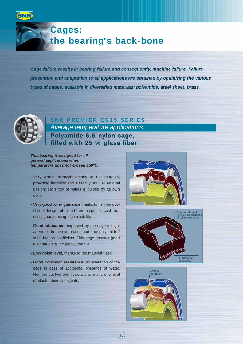
- Very good strength thanks to the material,
providing flexibility and elasticity, as well as dual
design: each row of rollers is guided by its own
cage.
- Very good roller guidance thanks to its « window
style » design, obtained from a specific cast pro-
cess, guaranteeing high reliability.
- Good lubrication, improved by the cage design:
apertures in the external shroud, low polyamide /
steel friction coefficient. This cage ensures good
distribution of the lubrication film.
- Low noise level, thanks to the material used.
- Good corrosion resistance: no alteration of the
cage in case of accidental presence of water.
Non-conductive and resistant to many chemical
or electrochemical agents.
Lubricationapertures
Contoured profile for a close guidanceof rolling elements
Addedlubricant
SNR PREMIER EG15 SERIES Average temperature applicationsPolyamide 6.6 nylon cage, filled with 25 % glass fiber
This bearing is designed for all general applications when temperature does not exceed 150°C.
11
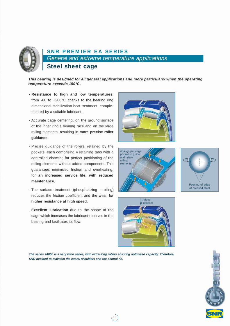
This bearing is designed for all general applications and more particularly when the operatingtemperature exceeds 150°C.
4 tangs per cage pocket to guide and retain rolling elements
Peening of edge of pressed steel
SNR PREMIER EA SERIES General and extreme temperature applicationsSteel sheet cage
- Resistance to high and low temperatures:
from -60 to +200°C, thanks to the bearing ring
dimensional stabilization heat treatment, comple-
mented by a suitable lubricant.
- Accurate cage centering, on the ground surface
of the inner ring's bearing race and on the large
rolling elements, resulting in more precise roller
guidance.
- Precise guidance of the rollers, retained by the
pockets, each comprising 4 retaining tabs with a
controlled chamfer, for perfect positioning of the
rolling elements without added components. This
guarantees minimized friction and overheating,
for an increased service life, with reduced
maintenance.
- The surface treatment (phosphatizing - oiling)
reduces the friction coefficient and the wear, for
higher resistance at high speed.
- Excellent lubrication due to the shape of the
cage which increases the lubricant reserves in the
bearing and facilitates its flow.
The series 24000 is a very wide series, with extra-long rollers ensuring optimized capacity. Therefore,
SNR decided to maintain the lateral shoulders and the central rib.
Addedlubricant
Cages: the bearing's back-bone
12
- Resistance to vibrations, by the solid one-piece
machined cage, which minimizes resonance
phenomena, and their induced failures.
- Strengthened roller retention under vibrations,
thanks to the lateral shoulders in the inner ring and
to the internal clearance control at installation. To
ensure correct operation in vibration applications,
the tolerances on the outer diameter, the bore and
the internal clearance are reduced.
- Special radial play: C4, utilizing the upper 2/3 of
the tolerance range, in order to perfectly control the
internal clearance after installation. This type of spe-
cial tolerance is also available in classes C0 and C3.
The vibratory mechanisms such as those found in shaker screens, crushers, grinders or constructionequipment engines, are the most demanding applications for spherical roller bearings.
SNR PREMIER EF800 SERIES High vibration applicationsSolid copper alloy cage (brass), reduced internal tolerance & clearance ranges
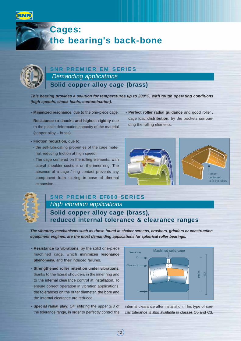
- Minimized resonance, due to the one-piece cage.
- Resistance to shocks and highest rigidity due
to the plastic deformation capacity of the material
(copper alloy – brass)
- Friction reduction, due to:
- the self-lubricating properties of the cage mate-
rial, reducing friction at high speed.
- The cage centered on the rolling elements, with
lateral shoulder sections on the inner ring. The
absence of a cage / ring contact prevents any
component from siezing in case of thermal
expansion.
- Perfect roller radial guidance and good roller /
cage load distribution, by the pockets surroun-
ding the rolling elements.
This bearing provides a solution for temperatures up to 200°C, with tough operating conditions(high speeds, shock loads, contamination).
SNR PREMIER EM SERIES Demanding applicationsSolid copper alloy cage (brass)
D
d
Clearance
ISO
EF8
00
Machined solid cageTolerances
Pocket contoured to fit the rollers
13
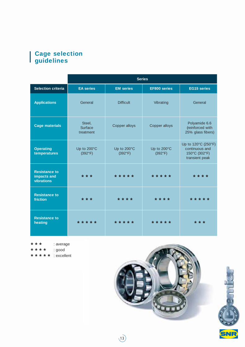
* * * : average
* * * * : good
* * * * * : excellent
Cage selection guidelines
Series
Selection criteria EA series EM series EF800 series EG15 series
Applications General Difficult Vibrating General
Steel, Polyamide 6.6Cage materials Surface Copper alloys Copper alloys (reinforced with
treatment 25% glass fibers)
Up to 120°C (250°F)Operating Up to 200°C Up to 200°C Up to 200°C continuous andtemperatures (392°F) (392°F) (392°F) 150°C (302°F)
transient peak
Resistance toimpacts and * * * * * * * * * * * * * * * * *vibrations
Resistance to friction * * * * * * * * * * * * * * * *
Resistance to heating * * * * * * * * * * * * * * * * * *
Suitable lubrication: critical for long service
14
Lubrication is an essential element for correct operation of the bearing. In fact, 70% of
premature failures are due to faulty lubrication. Viscosity is key, as well as lubricant
distribution between the components, due to geometry and surface conditions.
This point was particularly optimized in spherical roller bearings.
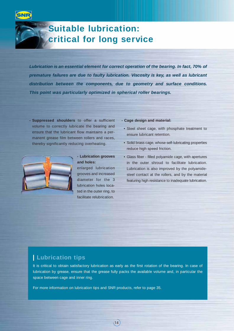
- Suppressed shoulders to offer a sufficient
volume to correctly lubricate the bearing and
ensure that the lubricant flow maintains a per-
manent grease film between rollers and races,
thereby significantly reducing overheating.
- Lubrication grooves
and holes:
enlarged lubrication
grooves and increased
diameter for the 3
lubrication holes loca-
ted in the outer ring, to
facilitate relubrication.
- Cage design and material:
• Steel sheet cage, with phosphate treatment to
ensure lubricant retention.
• Solid brass cage, whose self-lubricating properties
reduce high speed friction.
• Glass fiber - filled polyamide cage, with apertures
in the outer shroud to facilitate lubrication.
Lubrication is also improved by the polyamide-
steel contact at the rollers, and by the material
featuring high resistance to inadequate lubrication.
Lubrication tipsIt is critical to obtain satisfactory lubrication as early as the first rotation of the bearing. In case of
lubrication by grease, ensure that the grease fully packs the available volume and, in particular the
space between cage and inner ring.
For more information on lubrication tips and SNR products, refer to page 35.
15
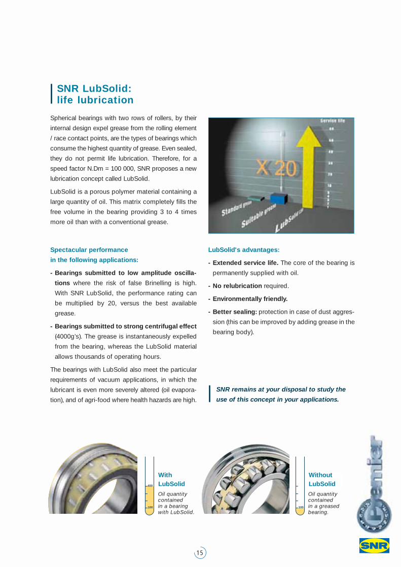
SNR LubSolid: life lubrication
Spherical bearings with two rows of rollers, by their
internal design expel grease from the rolling element
/ race contact points, are the types of bearings which
consume the highest quantity of grease. Even sealed,
they do not permit life lubrication. Therefore, for a
speed factor N.Dm = 100 000, SNR proposes a new
lubrication concept called LubSolid.
LubSolid is a porous polymer material containing a
large quantity of oil. This matrix completely fills the
free volume in the bearing providing 3 to 4 times
more oil than with a conventional grease.
Spectacular performance
in the following applications:
- Bearings submitted to low amplitude oscilla-
tions where the risk of false Brinelling is high.
With SNR LubSolid, the performance rating can
be multiplied by 20, versus the best available
grease.
- Bearings submitted to strong centrifugal effect
(4000g’s). The grease is instantaneously expelled
from the bearing, whereas the LubSolid material
allows thousands of operating hours.
The bearings with LubSolid also meet the particular
requirements of vacuum applications, in which the
lubricant is even more severely altered (oil evapora-
tion), and of agri-food where health hazards are high.
LubSolid's advantages:
- Extended service life. The core of the bearing is
permanently supplied with oil.
- No relubrication required.
- Environmentally friendly.
- Better sealing: protection in case of dust aggres-
sion (this can be improved by adding grease in the
bearing body).
SNR remains at your disposal to study the
use of this concept in your applications.
100
WithoutLubSolid
Oil quantitycontainedin a greasedbearing.
100
400
Oil quantitycontainedin a bearingwith LubSolid.
WithLubSolid
Speed: better knowledge to select the most appropriate bearing
16
The thermal reference speed is the inner ring rota-
ting speed for which thermal equilibrium is reached,
between heat produced by friction in the bearing
and thermal flow emitted through the bearing seat
(shaft and bearing housing), in reference conditions.
Reference conditions determining heat generation
by friction:
- Bearing reference temperature on fixed outer ring θr:
70°C.
- Bearing reference ambient temperature θAr: 20°C.
- Reference load P1r = 0,05 x C0r (5% of the basic
static load, taken as pure radial load).
- Lubricant: mineral oil without extreme pressure
additives, featuring, at θr = 70°C, a kinematic
viscosity νr = 12 mm2 /s (ISO VG 32).
- Lubrication method:
oil bath, with oil level up to, the center of the rolling
element at its lowest position.
- Bearing size range: up to and including a bore
diameter of 1,000 mm.
- Internal clearance: group « N ».
- Bearing rotation axis: horizontal.
- Fixed outer ring.
The reference conditions for grease lubrication are
determined so that the thermal reference speed is
identical to oil bath lubrication reference speed.
Thermal reference speed nθr (ISO 15312 standard)
The admissible limit speed depends on mechanical
limitations such as the ultimate failure strength of
the bearing components.
Limit speed
If you wish to exceed the admissible limit speed
indicated in the table (page 23-27), consult your
SNR contact.
17
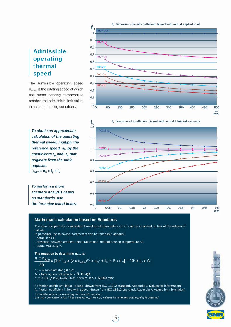
fp: Dimension-based coefficient, linked with actual applied load
The admissible operating speed
nadm is the rotating speed at which
the mean bearing temperature
reaches the admissible limit value,
in actual operating conditions.
Admissible operating thermal speed
To obtain an approximate
calculation of the operating
thermal speed, multiply the
reference speed nθr by the
coefficients fp and fv that
originate from the table
opposite. nadm = nθr x fp x fv
0 50 100 150 200 300250 350 400 450 5000
0,1
0,2
0,3
0,4
0,5
0,6
0,7
0,8
0,9
1P/C = 0,05
P/C = 0,1
P/C = 0,2
P/C =0,3
P/C =0,4
P/C =0,5
1,2
1,1
1
0,9
0,8
0,7
0,6
0,50 0,05 0,1 0,15 0,2 0,25 0,3 0,35 0,4 0,45 0,5
VG 15
VG 32
VG 46
VG 68
VG 150
VG 460
fv: Load-based coefficient, linked with actual lubricant viscosity
Mathematic calculation based on Standards
The standard permits a calculation based on all parameters which can be indicated, in lieu of the referencevalues. In particular, the following parameters can be taken into account:- actual load P,- deviation between ambient temperature and internal bearing temperature Δθ,- actual viscosity ν.
The equation to determine nadm is:
π x nadm x [10-7 f0r x (ν x nadm)2 /3 x dm3 + f1r x P x dm] = 103 x qr x Ar
30 dm = mean diameter (D+d)/2Ar = bearing journal area Ar = π (D+d)Bqr = 0.016 (Δθ/50) (Ar /50000)-0.34 w/mm2 if Ar > 50000 mm2
f1r: friction coefficient linked to load, drawn from ISO 15312 standard, Appendix A (values for information)f0r: friction coefficient linked with speed, drawn from ISO 15312 standard, Appendix A (values for information)
An iterative process is necessary to solve this equation. Starting from a zero or low initial value for nadm the nadm value is incremented until equality is obtained.
To perform a more
accurate analysis based
on standards, use
the formulae listed below.
dm(mm)
P/C
Technical information: fundamentals
18
StandardsThe SNR Premier spherical roller bearings meet
the requirements in the DIN 635-2 and ISO 15
standards.
MisalignmentThe SNR Premier spherical roller bearings admit
misalignment to the order of 0.5°, without reduction
in service life. However, this angle must be limited in
TolerancesThe SNR Premier spherical roller bearings are deli-
vered in standard precision class: ISO 492 standard.
Upon request, SNR can deliver bearings with redu-
ced tolerances, on one or more characteristics
(bore, outer diameter, rotation precision, inner ring,…).
order to remain within values in keeping with the
sealing system used.
The EF800 range features tight tolerances on the
outer diameter and the bore, as well as the reduced
internal clearance tolerance. They provide better
control of the residual play after installation, which
must remain as low as possible.
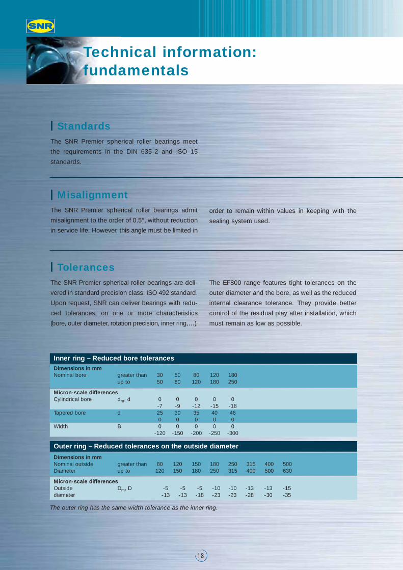
Inner ring – Reduced bore tolerancesDimensions in mmNominal bore greater than 30 50 80 120 180
up to 50 80 120 180 250
Micron-scale differencesCylindrical bore dm, d 0 0 0 0 0
-7 -9 -12 -15 -18Tapered bore d 25 30 35 40 46
0 0 0 0 0Width B 0 0 0 0 0
-120 -150 -200 -250 -300
Outer ring – Reduced tolerances on the outside diameter
Dimensions in mmNominal outside greater than 80 120 150 180 250 315 400 500Diameter up to 120 150 180 250 315 400 500 630
Micron-scale differencesOutside Dm, D -5 -5 -5 -10 -10 -13 -13 -15diameter -13 -13 -18 -23 -23 -28 -30 -35
The outer ring has the same width tolerance as the inner ring.
19
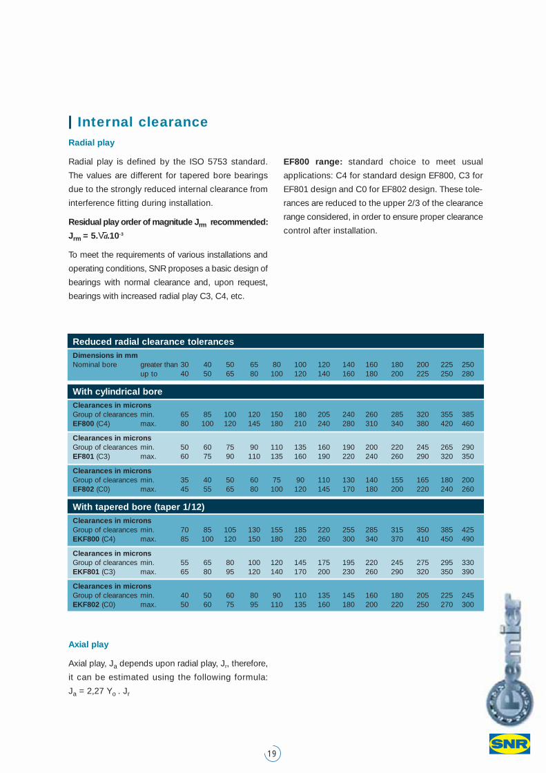
Internal clearance Radial play
Radial play is defined by the ISO 5753 standard.
The values are different for tapered bore bearings
due to the strongly reduced internal clearance from
interference fitting during installation.
Residual play order of magnitude Jrm recommended:
Jrm = 5.Vd.10-3
To meet the requirements of various installations and
operating conditions, SNR proposes a basic design of
bearings with normal clearance and, upon request,
bearings with increased radial play C3, C4, etc.
EF800 range: standard choice to meet usual
applications: C4 for standard design EF800, C3 for
EF801 design and C0 for EF802 design. These tole-
rances are reduced to the upper 2/3 of the clearance
range considered, in order to ensure proper clearance
control after installation.
Axial play
Axial play, Ja depends upon radial play, Jr, therefore,
it can be estimated using the following formula:
Ja = 2,27 Yo . Jr
Reduced radial clearance tolerancesDimensions in mmNominal bore greater than 30 40 50 65 80 100 120 140 160 180 200 225 250
up to 40 50 65 80 100 120 140 160 180 200 225 250 280
With cylindrical boreClearances in micronsGroup of clearances min. 65 85 100 120 150 180 205 240 260 285 320 355 385EF800 (C4) max. 80 100 120 145 180 210 240 280 310 340 380 420 460
Clearances in micronsGroup of clearances min. 50 60 75 90 110 135 160 190 200 220 245 265 290EF801 (C3) max. 60 75 90 110 135 160 190 220 240 260 290 320 350
Clearances in micronsGroup of clearances min. 35 40 50 60 75 90 110 130 140 155 165 180 200EF802 (C0) max. 45 55 65 80 100 120 145 170 180 200 220 240 260
With tapered bore (taper 1/12)Clearances in micronsGroup of clearances min. 70 85 105 130 155 185 220 255 285 315 350 385 425EKF800 (C4) max. 85 100 120 150 180 220 260 300 340 370 410 450 490
Clearances in micronsGroup of clearances min. 55 65 80 100 120 145 175 195 220 245 275 295 330EKF801 (C3) max. 65 80 95 120 140 170 200 230 260 290 320 350 390
Clearances in micronsGroup of clearances min. 40 50 60 80 90 110 135 145 160 180 205 225 245EKF802 (C0) max. 50 60 75 95 110 135 160 180 200 220 250 270 300
Technical information: fundamentals
20
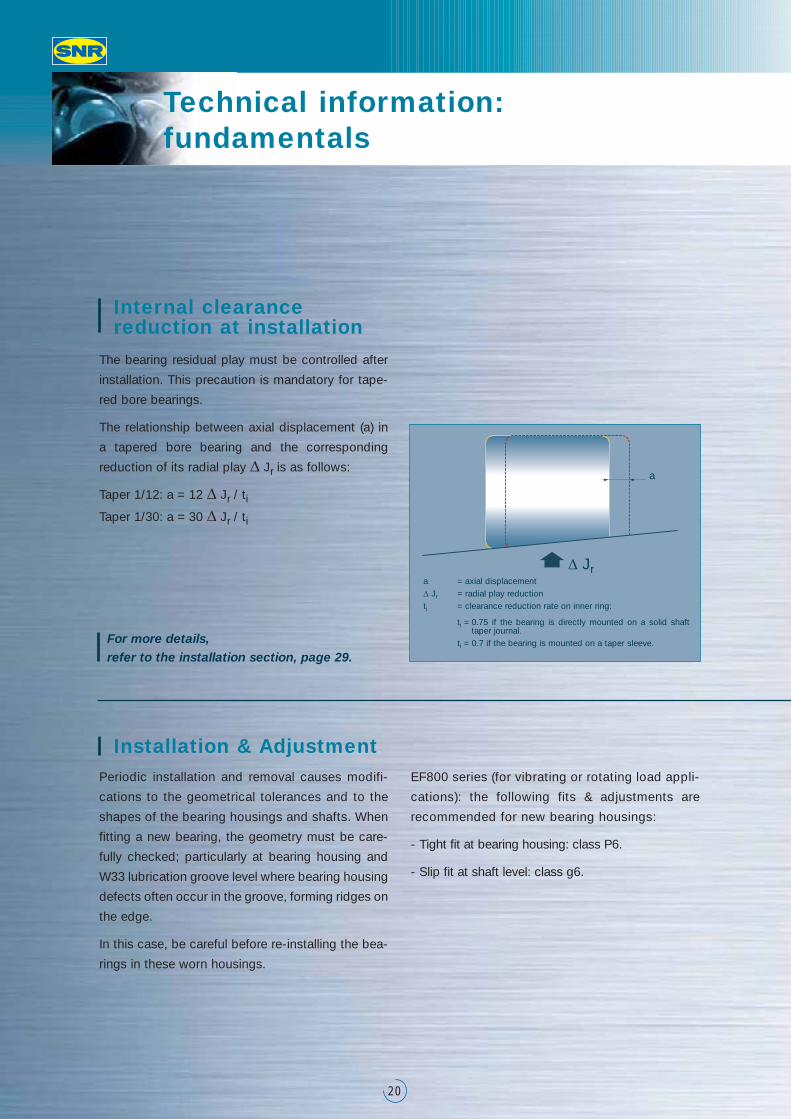
The bearing residual play must be controlled after
installation. This precaution is mandatory for tape-
red bore bearings.
The relationship between axial displacement (a) in
a tapered bore bearing and the corresponding
reduction of its radial play Δ Jr is as follows:
Taper 1/12: a = 12 Δ Jr / ti
Taper 1/30: a = 30 Δ Jr / ti
Periodic installation and removal causes modifi-
cations to the geometrical tolerances and to the
shapes of the bearing housings and shafts. When
fitting a new bearing, the geometry must be care-
fully checked; particularly at bearing housing and
W33 lubrication groove level where bearing housing
defects often occur in the groove, forming ridges on
the edge.
In this case, be careful before re-installing the bea-
rings in these worn housings.
EF800 series (for vibrating or rotating load appli-
cations): the following fits & adjustments are
recommended for new bearing housings:
- Tight fit at bearing housing: class P6.
- Slip fit at shaft level: class g6.
a = axial displacementΔ Jr = radial play reductionti = clearance reduction rate on inner ring:
ti = 0.75 if the bearing is directly mounted on a solid shafttaper journal.
ti = 0.7 if the bearing is mounted on a taper sleeve.For more details, refer to the installation section, page 29.
Installation & Adjustment
Internal clearance reduction at installation
a
Δ Jr
21
Cylindrical and tapered bores
The large majority of SNR Premier spherical roller
bearings are available both in cylindrical and tapered
bore (taper 1/12), identified by the suffix K. The
24000 and 24100 series bearings feature 1/30
taper, with K30 suffix.
Lubrication groove and holes
The SNR Premier spherical roller bearings are delivered
protected with an anti-oxident and not lubricated.
To facilitate lubrication, all SNR spherical roller
bearings, except those of the 21300 series, are
equipped with a lubrication groove, and 3 lubrication
holes on the outer ring, identified by suffix W33.
Their dimensions are indicated on pages 23 to 27.
Upon request, these bearings can be delivered
without lubrication groove or holes.
For vertical shaft applications, particular attention
must be paid to the lubricant supply. SNR recom-
mends oil lubrication.
The values mentioned in the tables on pages 23
to 27 concern the maximum value of r1 and the
shoulder section diameter.
For adapter sleeve mounting, the bearing ring
dimensions must be taken into account.
Fitting dimensions
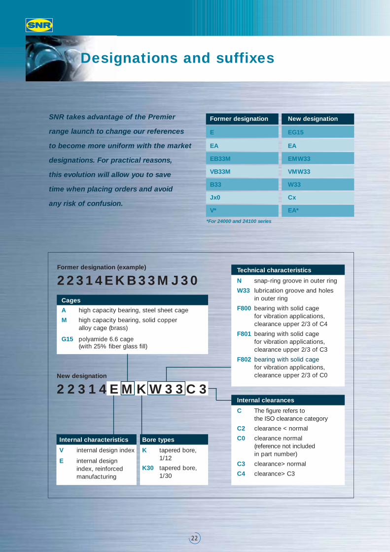
Designations and suffixes
22
SNR takes advantage of the Premier
range launch to change our references
to become more uniform with the market
designations. For practical reasons,
this evolution will allow you to save
time when placing orders and avoid
any risk of confusion.
*For 24000 and 24100 series
New designation
2 2 3 1 4 E M K W 3 3 C 3
Former designation (example)
2 2 3 1 4 E K B 3 3 M J 3 0
Internal characteristics
V internal design index
E internal designindex, reinforcedmanufacturing
Bore types
K tapered bore, 1/12
K30 tapered bore, 1/30
Technical characteristics
N snap-ring groove in outer ring
W33 lubrication groove and holes in outer ring
F800 bearing with solid cage for vibration applications, clearance upper 2/3 of C4
F801 bearing with solid cage for vibration applications, clearance upper 2/3 of C3
F802 bearing with solid cage for vibration applications, clearance upper 2/3 of C0
Internal clearances
C The figure refers to the ISO clearance category
C2 clearance < normal
C0 clearance normal (reference not includedin part number)
C3 clearance> normal
C4 clearance> C3
Cages
A high capacity bearing, steel sheet cage
M high capacity bearing, solid copper alloy cage (brass)
G15 polyamide 6.6 cage (with 25% fiber glass fill)
Former designation
E
EA
EB33M
VB33M
B33
Jx0
V*
New designation
EG15
EA
EMW33
VMW33
W33
Cx
EA*
Range
23
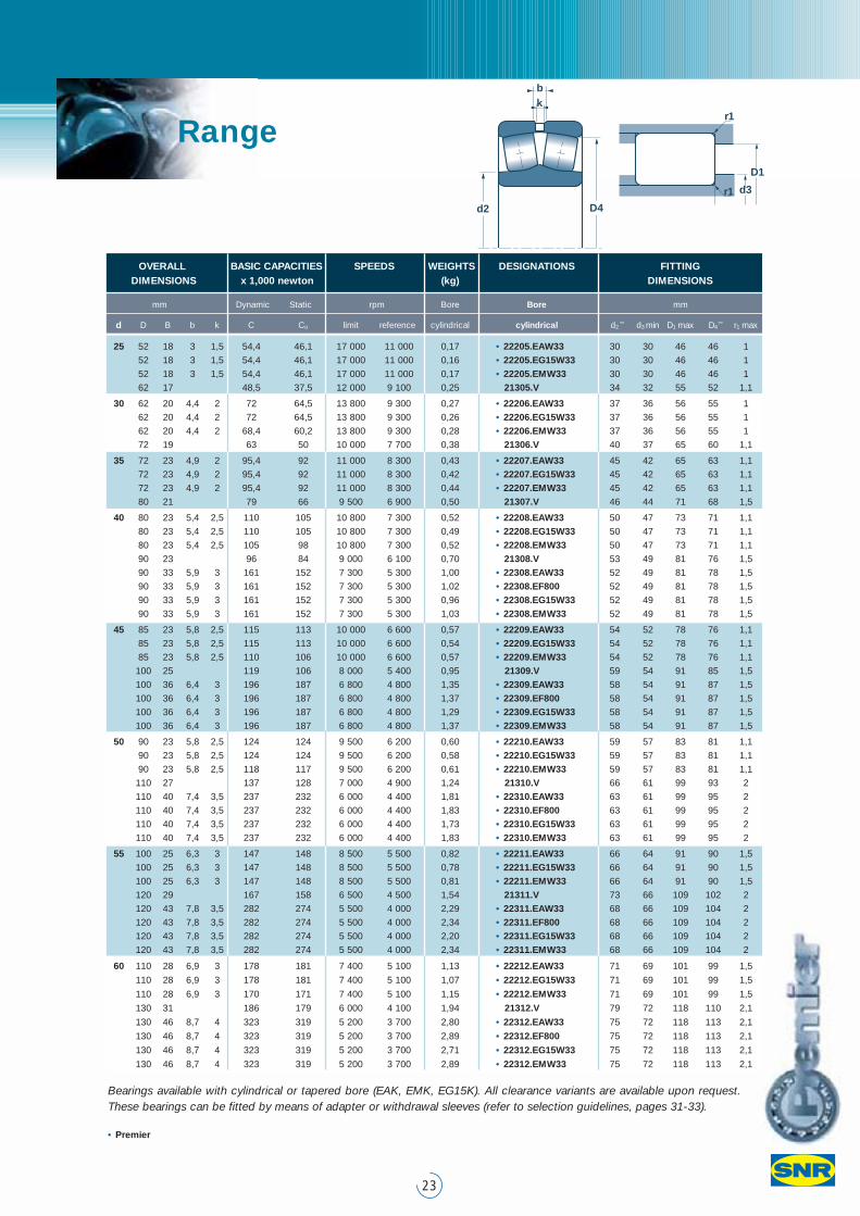
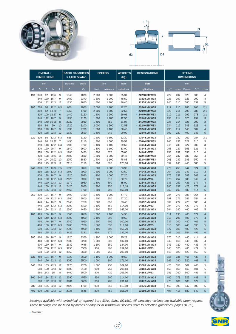
Bearings available with cylindrical or tapered bore (EAK, EMK, EG15K). All clearance variants are available upon request.These bearings can be fitted by means of adapter or withdrawal sleeves (refer to selection guidelines, pages 31-33).
• Premier
OVERALL BASIC CAPACITIES SPEEDS WEIGHTS DESIGNATIONS FITTINGDIMENSIONS x 1,000 newton (kg) DIMENSIONS
mm Dynamic Static rpm Bore Bore mm
d D B b k C Co limit reference cylindrical cylindrical d2 d3 min D1 max D4 r1 max
25 52 18 3 1,5 54,4 46,1 17 000 11 000 0,17 • 22205.EAW33 30 30 46 46 1
52 18 3 1,5 54,4 46,1 17 000 11 000 0,16 • 22205.EG15W33 30 30 46 46 1
52 18 3 1,5 54,4 46,1 17 000 11 000 0,17 • 22205.EMW33 30 30 46 46 1
62 17 48,5 37,5 12 000 9 100 0,25 21305.V 34 32 55 52 1,1
30 62 20 4,4 2 72 64,5 13 800 9 300 0,27 • 22206.EAW33 37 36 56 55 1
62 20 4,4 2 72 64,5 13 800 9 300 0,26 • 22206.EG15W33 37 36 56 55 1
62 20 4,4 2 68,4 60,2 13 800 9 300 0,28 • 22206.EMW33 37 36 56 55 1
72 19 63 50 10 000 7 700 0,38 21306.V 40 37 65 60 1,1
35 72 23 4,9 2 95,4 92 11 000 8 300 0,43 • 22207.EAW33 45 42 65 63 1,1
72 23 4,9 2 95,4 92 11 000 8 300 0,42 • 22207.EG15W33 45 42 65 63 1,1
72 23 4,9 2 95,4 92 11 000 8 300 0,44 • 22207.EMW33 45 42 65 63 1,1
80 21 79 66 9 500 6 900 0,50 21307.V 46 44 71 68 1,5
40 80 23 5,4 2,5 110 105 10 800 7 300 0,52 • 22208.EAW33 50 47 73 71 1,1
80 23 5,4 2,5 110 105 10 800 7 300 0,49 • 22208.EG15W33 50 47 73 71 1,1
80 23 5,4 2,5 105 98 10 800 7 300 0,52 • 22208.EMW33 50 47 73 71 1,1
90 23 96 84 9 000 6 100 0,70 21308.V 53 49 81 76 1,5
90 33 5,9 3 161 152 7 300 5 300 1,00 • 22308.EAW33 52 49 81 78 1,5
90 33 5,9 3 161 152 7 300 5 300 1,02 • 22308.EF800 52 49 81 78 1,5
90 33 5,9 3 161 152 7 300 5 300 0,96 • 22308.EG15W33 52 49 81 78 1,5
90 33 5,9 3 161 152 7 300 5 300 1,03 • 22308.EMW33 52 49 81 78 1,5
45 85 23 5,8 2,5 115 113 10 000 6 600 0,57 • 22209.EAW33 54 52 78 76 1,1
85 23 5,8 2,5 115 113 10 000 6 600 0,54 • 22209.EG15W33 54 52 78 76 1,1
85 23 5,8 2,5 110 106 10 000 6 600 0,57 • 22209.EMW33 54 52 78 76 1,1
100 25 119 106 8 000 5 400 0,95 21309.V 59 54 91 85 1,5
100 36 6,4 3 196 187 6 800 4 800 1,35 • 22309.EAW33 58 54 91 87 1,5
100 36 6,4 3 196 187 6 800 4 800 1,37 • 22309.EF800 58 54 91 87 1,5
100 36 6,4 3 196 187 6 800 4 800 1,29 • 22309.EG15W33 58 54 91 87 1,5
100 36 6,4 3 196 187 6 800 4 800 1,37 • 22309.EMW33 58 54 91 87 1,5
50 90 23 5,8 2,5 124 124 9 500 6 200 0,60 • 22210.EAW33 59 57 83 81 1,1
90 23 5,8 2,5 124 124 9 500 6 200 0,58 • 22210.EG15W33 59 57 83 81 1,1
90 23 5,8 2,5 118 117 9 500 6 200 0,61 • 22210.EMW33 59 57 83 81 1,1
110 27 137 128 7 000 4 900 1,24 21310.V 66 61 99 93 2
110 40 7,4 3,5 237 232 6 000 4 400 1,81 • 22310.EAW33 63 61 99 95 2
110 40 7,4 3,5 237 232 6 000 4 400 1,83 • 22310.EF800 63 61 99 95 2
110 40 7,4 3,5 237 232 6 000 4 400 1,73 • 22310.EG15W33 63 61 99 95 2
110 40 7,4 3,5 237 232 6 000 4 400 1,83 • 22310.EMW33 63 61 99 95 2
55 100 25 6,3 3 147 148 8 500 5 500 0,82 • 22211.EAW33 66 64 91 90 1,5
100 25 6,3 3 147 148 8 500 5 500 0,78 • 22211.EG15W33 66 64 91 90 1,5
100 25 6,3 3 147 148 8 500 5 500 0,81 • 22211.EMW33 66 64 91 90 1,5
120 29 167 158 6 500 4 500 1,54 21311.V 73 66 109 102 2
120 43 7,8 3,5 282 274 5 500 4 000 2,29 • 22311.EAW33 68 66 109 104 2
120 43 7,8 3,5 282 274 5 500 4 000 2,34 • 22311.EF800 68 66 109 104 2
120 43 7,8 3,5 282 274 5 500 4 000 2,20 • 22311.EG15W33 68 66 109 104 2
120 43 7,8 3,5 282 274 5 500 4 000 2,34 • 22311.EMW33 68 66 109 104 2
60 110 28 6,9 3 178 181 7 400 5 100 1,13 • 22212.EAW33 71 69 101 99 1,5
110 28 6,9 3 178 181 7 400 5 100 1,07 • 22212.EG15W33 71 69 101 99 1,5
110 28 6,9 3 170 171 7 400 5 100 1,15 • 22212.EMW33 71 69 101 99 1,5
130 31 186 179 6 000 4 100 1,94 21312.V 79 72 118 110 2,1
130 46 8,7 4 323 319 5 200 3 700 2,80 • 22312.EAW33 75 72 118 113 2,1
130 46 8,7 4 323 319 5 200 3 700 2,89 • 22312.EF800 75 72 118 113 2,1
130 46 8,7 4 323 319 5 200 3 700 2,71 • 22312.EG15W33 75 72 118 113 2,1
130 46 8,7 4 323 319 5 200 3 700 2,89 • 22312.EMW33 75 72 118 113 2,1
d2 D4
kb
D1
d3
r1
r1
Range
24
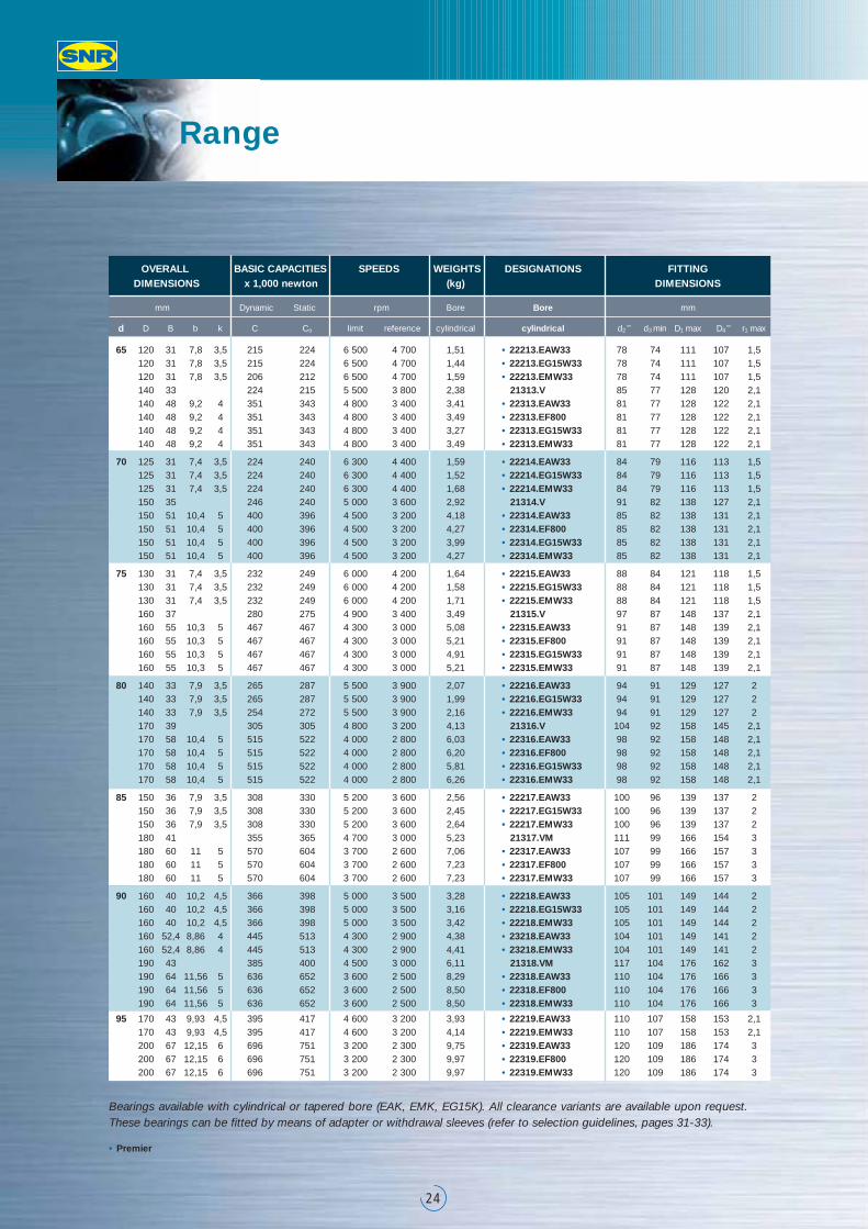
Bearings available with cylindrical or tapered bore (EAK, EMK, EG15K). All clearance variants are available upon request.These bearings can be fitted by means of adapter or withdrawal sleeves (refer to selection guidelines, pages 31-33).
• Premier
OVERALL BASIC CAPACITIES SPEEDS WEIGHTS DESIGNATIONS FITTINGDIMENSIONS x 1,000 newton (kg) DIMENSIONS
mm Dynamic Static rpm Bore Bore mm
d D B b k C Co limit reference cylindrical cylindrical d2 d3 min D1 max D4 r1 max
65 120 31 7,8 3,5 215 224 6 500 4 700 1,51 • 22213.EAW33 78 74 111 107 1,5120 31 7,8 3,5 215 224 6 500 4 700 1,44 • 22213.EG15W33 78 74 111 107 1,5120 31 7,8 3,5 206 212 6 500 4 700 1,59 • 22213.EMW33 78 74 111 107 1,5140 33 224 215 5 500 3 800 2,38 21313.V 85 77 128 120 2,1140 48 9,2 4 351 343 4 800 3 400 3,41 • 22313.EAW33 81 77 128 122 2,1140 48 9,2 4 351 343 4 800 3 400 3,49 • 22313.EF800 81 77 128 122 2,1140 48 9,2 4 351 343 4 800 3 400 3,27 • 22313.EG15W33 81 77 128 122 2,1140 48 9,2 4 351 343 4 800 3 400 3,49 • 22313.EMW33 81 77 128 122 2,1
70 125 31 7,4 3,5 224 240 6 300 4 400 1,59 • 22214.EAW33 84 79 116 113 1,5125 31 7,4 3,5 224 240 6 300 4 400 1,52 • 22214.EG15W33 84 79 116 113 1,5125 31 7,4 3,5 224 240 6 300 4 400 1,68 • 22214.EMW33 84 79 116 113 1,5150 35 246 240 5 000 3 600 2,92 21314.V 91 82 138 127 2,1150 51 10,4 5 400 396 4 500 3 200 4,18 • 22314.EAW33 85 82 138 131 2,1150 51 10,4 5 400 396 4 500 3 200 4,27 • 22314.EF800 85 82 138 131 2,1150 51 10,4 5 400 396 4 500 3 200 3,99 • 22314.EG15W33 85 82 138 131 2,1150 51 10,4 5 400 396 4 500 3 200 4,27 • 22314.EMW33 85 82 138 131 2,1
75 130 31 7,4 3,5 232 249 6 000 4 200 1,64 • 22215.EAW33 88 84 121 118 1,5130 31 7,4 3,5 232 249 6 000 4 200 1,58 • 22215.EG15W33 88 84 121 118 1,5130 31 7,4 3,5 232 249 6 000 4 200 1,71 • 22215.EMW33 88 84 121 118 1,5160 37 280 275 4 900 3 400 3,49 21315.V 97 87 148 137 2,1160 55 10,3 5 467 467 4 300 3 000 5,08 • 22315.EAW33 91 87 148 139 2,1160 55 10,3 5 467 467 4 300 3 000 5,21 • 22315.EF800 91 87 148 139 2,1160 55 10,3 5 467 467 4 300 3 000 4,91 • 22315.EG15W33 91 87 148 139 2,1160 55 10,3 5 467 467 4 300 3 000 5,21 • 22315.EMW33 91 87 148 139 2,1
80 140 33 7,9 3,5 265 287 5 500 3 900 2,07 • 22216.EAW33 94 91 129 127 2140 33 7,9 3,5 265 287 5 500 3 900 1,99 • 22216.EG15W33 94 91 129 127 2140 33 7,9 3,5 254 272 5 500 3 900 2,16 • 22216.EMW33 94 91 129 127 2170 39 305 305 4 800 3 200 4,13 21316.V 104 92 158 145 2,1170 58 10,4 5 515 522 4 000 2 800 6,03 • 22316.EAW33 98 92 158 148 2,1170 58 10,4 5 515 522 4 000 2 800 6,20 • 22316.EF800 98 92 158 148 2,1170 58 10,4 5 515 522 4 000 2 800 5,81 • 22316.EG15W33 98 92 158 148 2,1170 58 10,4 5 515 522 4 000 2 800 6,26 • 22316.EMW33 98 92 158 148 2,1
85 150 36 7,9 3,5 308 330 5 200 3 600 2,56 • 22217.EAW33 100 96 139 137 2150 36 7,9 3,5 308 330 5 200 3 600 2,45 • 22217.EG15W33 100 96 139 137 2150 36 7,9 3,5 308 330 5 200 3 600 2,64 • 22217.EMW33 100 96 139 137 2180 41 355 365 4 700 3 000 5,23 21317.VM 111 99 166 154 3180 60 11 5 570 604 3 700 2 600 7,06 • 22317.EAW33 107 99 166 157 3180 60 11 5 570 604 3 700 2 600 7,23 • 22317.EF800 107 99 166 157 3180 60 11 5 570 604 3 700 2 600 7,23 • 22317.EMW33 107 99 166 157 3
90 160 40 10,2 4,5 366 398 5 000 3 500 3,28 • 22218.EAW33 105 101 149 144 2160 40 10,2 4,5 366 398 5 000 3 500 3,16 • 22218.EG15W33 105 101 149 144 2160 40 10,2 4,5 366 398 5 000 3 500 3,42 • 22218.EMW33 105 101 149 144 2160 52,4 8,86 4 445 513 4 300 2 900 4,38 • 23218.EAW33 104 101 149 141 2160 52,4 8,86 4 445 513 4 300 2 900 4,41 • 23218.EMW33 104 101 149 141 2190 43 385 400 4 500 3 000 6,11 21318.VM 117 104 176 162 3190 64 11,56 5 636 652 3 600 2 500 8,29 • 22318.EAW33 110 104 176 166 3190 64 11,56 5 636 652 3 600 2 500 8,50 • 22318.EF800 110 104 176 166 3190 64 11,56 5 636 652 3 600 2 500 8,50 • 22318.EMW33 110 104 176 166 3
95 170 43 9,93 4,5 395 417 4 600 3 200 3,93 • 22219.EAW33 110 107 158 153 2,1170 43 9,93 4,5 395 417 4 600 3 200 4,14 • 22219.EMW33 110 107 158 153 2,1200 67 12,15 6 696 751 3 200 2 300 9,75 • 22319.EAW33 120 109 186 174 3200 67 12,15 6 696 751 3 200 2 300 9,97 • 22319.EF800 120 109 186 174 3200 67 12,15 6 696 751 3 200 2 300 9,97 • 22319.EMW33 120 109 186 174 3
25
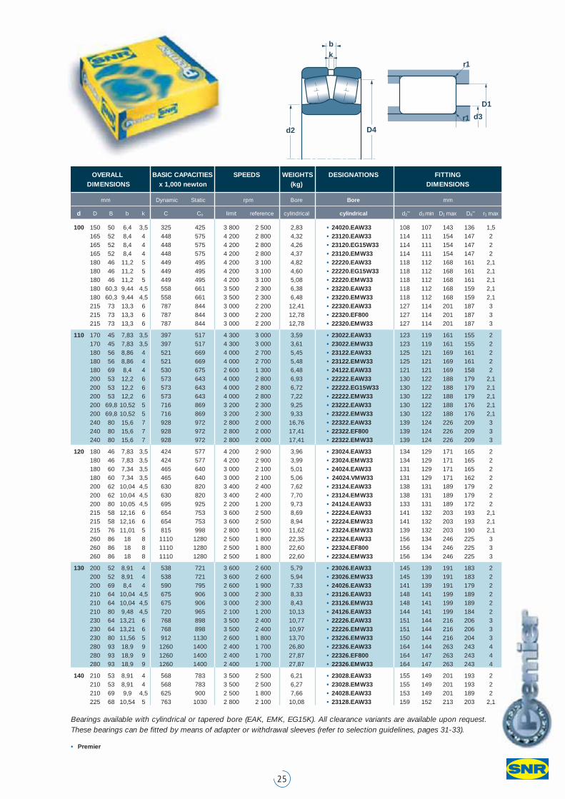
Bearings available with cylindrical or tapered bore (EAK, EMK, EG15K). All clearance variants are available upon request.These bearings can be fitted by means of adapter or withdrawal sleeves (refer to selection guidelines, pages 31-33).
• Premier
OVERALL BASIC CAPACITIES SPEEDS WEIGHTS DESIGNATIONS FITTINGDIMENSIONS x 1,000 newton (kg) DIMENSIONS
mm Dynamic Static rpm Bore Bore mm
d D B b k C Co limit reference cylindrical cylindrical d2 d3 min D1 max D4 r1 max
100 150 50 6,4 3,5 325 425 3 800 2 500 2,83 • 24020.EAW33 108 107 143 136 1,5165 52 8,4 4 448 575 4 200 2 800 4,32 • 23120.EAW33 114 111 154 147 2165 52 8,4 4 448 575 4 200 2 800 4,26 • 23120.EG15W33 114 111 154 147 2165 52 8,4 4 448 575 4 200 2 800 4,37 • 23120.EMW33 114 111 154 147 2180 46 11,2 5 449 495 4 200 3 100 4,82 • 22220.EAW33 118 112 168 161 2,1180 46 11,2 5 449 495 4 200 3 100 4,60 • 22220.EG15W33 118 112 168 161 2,1180 46 11,2 5 449 495 4 200 3 100 5,08 • 22220.EMW33 118 112 168 161 2,1180 60,3 9,44 4,5 558 661 3 500 2 300 6,38 • 23220.EAW33 118 112 168 159 2,1180 60,3 9,44 4,5 558 661 3 500 2 300 6,48 • 23220.EMW33 118 112 168 159 2,1215 73 13,3 6 787 844 3 000 2 200 12,41 • 22320.EAW33 127 114 201 187 3215 73 13,3 6 787 844 3 000 2 200 12,78 • 22320.EF800 127 114 201 187 3215 73 13,3 6 787 844 3 000 2 200 12,78 • 22320.EMW33 127 114 201 187 3
110 170 45 7,83 3,5 397 517 4 300 3 000 3,59 • 23022.EAW33 123 119 161 155 2170 45 7,83 3,5 397 517 4 300 3 000 3,61 • 23022.EMW33 123 119 161 155 2180 56 8,86 4 521 669 4 000 2 700 5,45 • 23122.EAW33 125 121 169 161 2180 56 8,86 4 521 669 4 000 2 700 5,48 • 23122.EMW33 125 121 169 161 2180 69 8,4 4 530 675 2 600 1 300 6,48 • 24122.EAW33 121 121 169 158 2200 53 12,2 6 573 643 4 000 2 800 6,93 • 22222.EAW33 130 122 188 179 2,1200 53 12,2 6 573 643 4 000 2 800 6,72 • 22222.EG15W33 130 122 188 179 2,1200 53 12,2 6 573 643 4 000 2 800 7,22 • 22222.EMW33 130 122 188 179 2,1200 69,8 10,52 5 716 869 3 200 2 300 9,25 • 23222.EAW33 130 122 188 176 2,1200 69,8 10,52 5 716 869 3 200 2 300 9,33 • 23222.EMW33 130 122 188 176 2,1240 80 15,6 7 928 972 2 800 2 000 16,76 • 22322.EAW33 139 124 226 209 3240 80 15,6 7 928 972 2 800 2 000 17,41 • 22322.EF800 139 124 226 209 3240 80 15,6 7 928 972 2 800 2 000 17,41 • 22322.EMW33 139 124 226 209 3
120 180 46 7,83 3,5 424 577 4 200 2 900 3,96 • 23024.EAW33 134 129 171 165 2180 46 7,83 3,5 424 577 4 200 2 900 3,99 • 23024.EMW33 134 129 171 165 2180 60 7,34 3,5 465 640 3 000 2 100 5,01 • 24024.EAW33 131 129 171 165 2180 60 7,34 3,5 465 640 3 000 2 100 5,06 • 24024.VMW33 131 129 171 162 2200 62 10,04 4,5 630 820 3 400 2 400 7,62 • 23124.EAW33 138 131 189 179 2200 62 10,04 4,5 630 820 3 400 2 400 7,70 • 23124.EMW33 138 131 189 179 2200 80 10,05 4,5 695 925 2 200 1 200 9,73 • 24124.EAW33 133 131 189 172 2215 58 12,16 6 654 753 3 600 2 500 8,69 • 22224.EAW33 141 132 203 193 2,1215 58 12,16 6 654 753 3 600 2 500 8,94 • 22224.EMW33 141 132 203 193 2,1215 76 11,01 5 815 998 2 800 1 900 11,62 • 23224.EMW33 139 132 203 190 2,1260 86 18 8 1110 1280 2 500 1 800 22,35 • 22324.EAW33 156 134 246 225 3260 86 18 8 1110 1280 2 500 1 800 22,60 • 22324.EF800 156 134 246 225 3260 86 18 8 1110 1280 2 500 1 800 22,60 • 22324.EMW33 156 134 246 225 3
130 200 52 8,91 4 538 721 3 600 2 600 5,79 • 23026.EAW33 145 139 191 183 2200 52 8,91 4 538 721 3 600 2 600 5,94 • 23026.EMW33 145 139 191 183 2200 69 8,4 4 590 795 2 600 1 900 7,33 • 24026.EAW33 141 139 191 179 2210 64 10,04 4,5 675 906 3 000 2 300 8,33 • 23126.EAW33 148 141 199 189 2210 64 10,04 4,5 675 906 3 000 2 300 8,43 • 23126.EMW33 148 141 199 189 2210 80 9,48 4,5 720 965 2 100 1 200 10,13 • 24126.EAW33 144 141 199 184 2230 64 13,21 6 768 898 3 500 2 400 10,77 • 22226.EAW33 151 144 216 206 3230 64 13,21 6 768 898 3 500 2 400 10,97 • 22226.EMW33 151 144 216 206 3230 80 11,56 5 912 1130 2 600 1 800 13,70 • 23226.EMW33 150 144 216 204 3280 93 18,9 9 1260 1400 2 400 1 700 26,80 • 22326.EAW33 164 144 263 243 4280 93 18,9 9 1260 1400 2 400 1 700 27,87 • 22326.EF800 164 147 263 243 4280 93 18,9 9 1260 1400 2 400 1 700 27,87 • 22326.EMW33 164 147 263 243 4
140 210 53 8,91 4 568 783 3 500 2 500 6,21 • 23028.EAW33 155 149 201 193 2210 53 8,91 4 568 783 3 500 2 500 6,27 • 23028.EMW33 155 149 201 193 2210 69 9,9 4,5 625 900 2 500 1 800 7,66 • 24028.EAW33 153 149 201 189 2225 68 10,54 5 763 1030 2 800 2 100 10,08 • 23128.EAW33 159 152 213 203 2,1
d2 D4
kb
D1
d3
r1
r1
Range
26
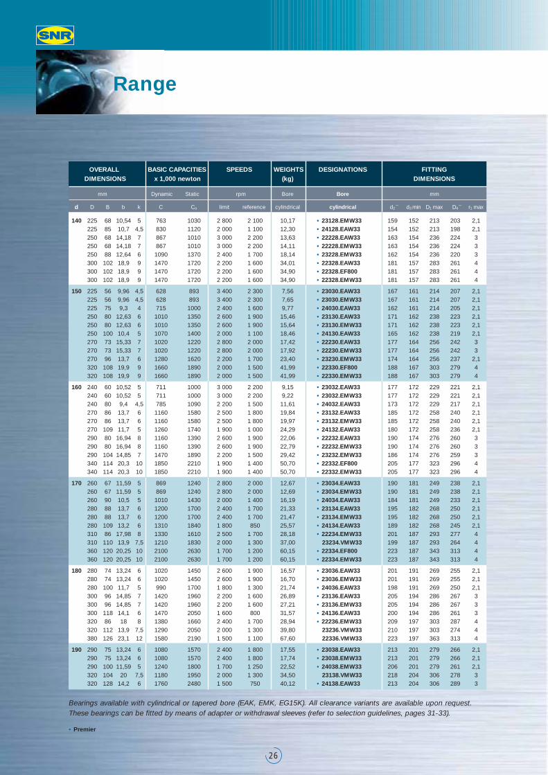
Bearings available with cylindrical or tapered bore (EAK, EMK, EG15K). All clearance variants are available upon request.These bearings can be fitted by means of adapter or withdrawal sleeves (refer to selection guidelines, pages 31-33).
• Premier
OVERALL BASIC CAPACITIES SPEEDS WEIGHTS DESIGNATIONS FITTINGDIMENSIONS x 1,000 newton (kg) DIMENSIONS
mm Dynamic Static rpm Bore Bore mm
d D B b k C Co limit reference cylindrical cylindrical d2 d3 min D1 max D4 r1 max
140 225 68 10,54 5 763 1030 2 800 2 100 10,17 • 23128.EMW33 159 152 213 203 2,1225 85 10,7 4,5 830 1120 2 000 1 100 12,30 • 24128.EAW33 154 152 213 198 2,1250 68 14,18 7 867 1010 3 000 2 200 13,63 • 22228.EAW33 163 154 236 224 3250 68 14,18 7 867 1010 3 000 2 200 14,11 • 22228.EMW33 163 154 236 224 3250 88 12,64 6 1090 1370 2 400 1 700 18,14 • 23228.EMW33 162 154 236 220 3300 102 18,9 9 1470 1720 2 200 1 600 34,01 • 22328.EAW33 181 157 283 261 4300 102 18,9 9 1470 1720 2 200 1 600 34,90 • 22328.EF800 181 157 283 261 4300 102 18,9 9 1470 1720 2 200 1 600 34,90 • 22328.EMW33 181 157 283 261 4
150 225 56 9,96 4,5 628 893 3 400 2 300 7,56 • 23030.EAW33 167 161 214 207 2,1225 56 9,96 4,5 628 893 3 400 2 300 7,65 • 23030.EMW33 167 161 214 207 2,1225 75 9,3 4 715 1000 2 400 1 600 9,77 • 24030.EAW33 162 161 214 205 2,1250 80 12,63 6 1010 1350 2 600 1 900 15,46 • 23130.EAW33 171 162 238 223 2,1250 80 12,63 6 1010 1350 2 600 1 900 15,64 • 23130.EMW33 171 162 238 223 2,1250 100 10,4 5 1070 1400 2 000 1 100 18,46 • 24130.EAW33 165 162 238 219 2,1270 73 15,33 7 1020 1220 2 800 2 000 17,42 • 22230.EAW33 177 164 256 242 3270 73 15,33 7 1020 1220 2 800 2 000 17,92 • 22230.EMW33 177 164 256 242 3270 96 13,7 6 1280 1620 2 200 1 700 23,40 • 23230.EMW33 174 164 256 237 2,1320 108 19,9 9 1660 1890 2 000 1 500 41,99 • 22330.EF800 188 167 303 279 4320 108 19,9 9 1660 1890 2 000 1 500 41,99 • 22330.EMW33 188 167 303 279 4
160 240 60 10,52 5 711 1000 3 000 2 200 9,15 • 23032.EAW33 177 172 229 221 2,1240 60 10,52 5 711 1000 3 000 2 200 9,22 • 23032.EMW33 177 172 229 221 2,1240 80 9,4 4,5 785 1090 2 200 1 500 11,61 • 24032.EAW33 173 172 229 217 2,1270 86 13,7 6 1160 1580 2 500 1 800 19,84 • 23132.EAW33 185 172 258 240 2,1270 86 13,7 6 1160 1580 2 500 1 800 19,97 • 23132.EMW33 185 172 258 240 2,1270 109 11,7 5 1260 1740 1 900 1 000 24,29 • 24132.EAW33 180 172 258 236 2,1290 80 16,94 8 1160 1390 2 600 1 900 22,06 • 22232.EAW33 190 174 276 260 3290 80 16,94 8 1160 1390 2 600 1 900 22,79 • 22232.EMW33 190 174 276 260 3290 104 14,85 7 1470 1890 2 200 1 500 29,42 • 23232.EMW33 186 174 276 259 3340 114 20,3 10 1850 2210 1 900 1 400 50,70 • 22332.EF800 205 177 323 296 4340 114 20,3 10 1850 2210 1 900 1 400 50,70 • 22332.EMW33 205 177 323 296 4
170 260 67 11,59 5 869 1240 2 800 2 000 12,67 • 23034.EAW33 190 181 249 238 2,1260 67 11,59 5 869 1240 2 800 2 000 12,69 • 23034.EMW33 190 181 249 238 2,1260 90 10,5 5 1010 1430 2 000 1 400 16,19 • 24034.EAW33 184 181 249 233 2,1280 88 13,7 6 1200 1700 2 400 1 700 21,33 • 23134.EAW33 195 182 268 250 2,1280 88 13,7 6 1200 1700 2 400 1 700 21,47 • 23134.EMW33 195 182 268 250 2,1280 109 13,2 6 1310 1840 1 800 850 25,57 • 24134.EAW33 189 182 268 245 2,1310 86 17,98 8 1330 1610 2 500 1 700 28,18 • 22234.EMW33 201 187 293 277 4310 110 13,9 7,5 1210 1830 2 000 1 300 37,00 23234.VMW33 199 187 293 264 4360 120 20,25 10 2100 2630 1 700 1 200 60,15 • 22334.EF800 223 187 343 313 4360 120 20,25 10 2100 2630 1 700 1 200 60,15 • 22334.EMW33 223 187 343 313 4
180 280 74 13,24 6 1020 1450 2 600 1 900 16,57 • 23036.EAW33 201 191 269 255 2,1280 74 13,24 6 1020 1450 2 600 1 900 16,70 • 23036.EMW33 201 191 269 255 2,1280 100 11,7 5 990 1700 1 800 1 300 21,74 • 24036.EAW33 198 191 269 250 2,1300 96 14,85 7 1420 1960 2 200 1 600 26,89 • 23136.EAW33 205 194 286 267 3300 96 14,85 7 1420 1960 2 200 1 600 27,21 • 23136.EMW33 205 194 286 267 3300 118 14,1 6 1470 2050 1 600 800 31,57 • 24136.EAW33 200 194 286 261 3320 86 18 8 1380 1660 2 400 1 700 28,94 • 22236.EMW33 209 197 303 287 4320 112 13,9 7,5 1290 2050 2 000 1 300 39,80 23236.VMW33 210 197 303 274 4380 126 23,1 12 1580 2190 1 500 1 100 67,60 22336.VMW33 223 197 363 313 4
190 290 75 13,24 6 1080 1570 2 400 1 800 17,55 • 23038.EAW33 213 201 279 266 2,1290 75 13,24 6 1080 1570 2 400 1 800 17,74 • 23038.EMW33 213 201 279 266 2,1290 100 11,59 5 1240 1800 1 700 1 250 22,52 • 24038.EMW33 206 201 279 261 2,1320 104 20 7,5 1180 1950 2 000 1 300 34,50 23138.VMW33 218 204 306 278 3320 128 14,2 6 1760 2480 1 500 750 40,12 • 24138.EAW33 213 204 306 289 3
27
Bearings available with cylindrical or tapered bore (EAK, EMK, EG15K). All clearance variants are available upon request.These bearings can be fitted by means of adapter or withdrawal sleeves (refer to selection guidelines, pages 31-33).
• Premier
OVERALL BASIC CAPACITIES SPEEDS WEIGHTS DESIGNATIONS FITTINGDIMENSIONS x 1,000 newton (kg) DIMENSIONS
mm Dynamic Static rpm Bore Bore mm
d D B b k C Co limit reference cylindrical cylindrical d2 d3 min D1 max D4 r1 max
190 340 92 19,6 9 1540 1870 2 200 1 600 35,31 • 22238.EMW33 222 207 323 305 4340 120 16,7 9 1480 2370 1 800 1 200 48,50 23238.VMW33 223 207 323 290 4400 132 22,3 12 1830 2650 1 500 1 100 76,40 22338.VMW33 240 210 380 332 5
200 280 60 12,2 6,3 620 1000 2 000 1 700 12,20 23940.VMW33 217 210 283 263 2,1310 82 14,28 7 1250 1790 2 200 1 700 22,56 • 23040.EMW33 223 211 299 283 2,1310 109 12,67 6 1440 2120 1 500 1 200 29,05 • 24040.EMW33 219 211 299 278 2,1340 112 16,7 9 1290 2120 1 700 1 200 42,50 23140.VMW33 230 214 326 294 3340 140 16,98 8 2030 2930 1 400 650 51,07 • 24140.EMW33 225 214 326 292 3360 98 20 10 1720 2100 2 000 1 500 42,53 • 22240.EMW33 234 217 343 323 4360 128 16,7 9 1630 2700 1 600 1 100 58,40 23240.VMW33 238 217 343 307 4420 138 22,3 12 1830 2650 1 400 940 99,00 22340.VMW33 302 220 400 346 5
220 300 60 12,2 6,3 665 1120 1 800 1 500 12,30 23944.VMW33 237 230 269 284 2,1340 90 15,37 7 1450 2110 1 900 1 500 29,52 • 23044.EMW33 246 233 327 310 3340 118 12,2 6,3 1400 2700 1 400 1 100 39,50 24044.VMW33 246 233 327 302 3370 120 20,7 9 1540 2600 1 500 1 100 53,00 23144.VMW33 253 237 353 321 4370 150 12,2 6,3 1900 3450 1 300 670 65,60 24144.VW33 253 237 353 316 4400 108 20,6 11 2100 2690 1 800 1 300 59,47 • 22244.EMW33 264 237 383 358 4400 144 20,02 10 2750 3830 1 500 1 100 78,83 • 23244.EMW33 261 237 383 350 4460 145 22,3 12 2110 3150 1 300 890 125,00 22344.VMW33 332 240 440 380 5
240 360 92 13,9 7,5 1090 2050 1 500 1 300 33,98 23048.VMW33 270 253 347 324 3360 118 12,2 6,3 1500 2900 1 300 1 000 43,60 24048.VMW33 264 253 347 319 3400 128 16,7 9 1720 2950 1 400 1 000 67,20 23148.VMW33 276 257 383 348 4400 160 12,2 6,3 2120 3900 1 200 610 80,70 24148.VW33 270 257 383 342 4440 120 22,3 12 1170 1950 1 600 890 85,00 22248.VMW33 333 257 423 377 4440 160 22,3 12 2420 3950 1 300 950 113,18 23248.VMW33 285 257 423 372 4500 155 22,3 12 2450 3700 1 300 790 159,00 22348.VMW33 362 260 480 414 5
260 400 104 16,7 9 1490 2430 1 400 1 200 47,70 23052.VMW33 284 275 385 364 4400 140 12,2 6,3 1900 3800 1 200 950 67,20 24052.VMW33 291 275 385 354 4440 144 16,7 9 2140 3750 1 300 950 93,40 23152.VMW33 302 277 423 380 4440 180 12,2 6,3 2700 5100 1 100 560 114,00 24152.VW33 294 277 423 373 4480 174 22,3 12 2700 4450 1 200 850 147,00 23252.VMW33 364 280 460 405 5
280 420 106 16,7 9 1500 2850 1 300 1 100 54,95 23056.VMW33 311 295 405 379 4420 140 12,2 6,3 2000 4000 1 100 900 70,50 24056.VMW33 318 295 405 375 4460 146 16,7 9 2240 4050 1 200 900 100,00 23156.VMW33 322 300 440 401 5460 180 12,2 6,3 2700 5200 1 000 530 119,00 24156.VW33 315 300 440 396 5500 176 22,3 12 2900 4900 1 100 800 157,20 23256.VMW33 327 300 480 426 5580 175 22,3 12 3429 5182 950 670 232,00 22356.VMW33 437 306 554 493 6
300 460 118 16,7 9 1820 3350 1 200 1 000 75,27 23060.VMW33 376 315 445 414 4460 160 12,2 6,3 2500 5200 1 000 800 102,00 24060.VMW33 343 315 445 407 4500 160 16,7 9 2632 4645 1 100 850 134,00 23160.VMW33 346 320 480 435 5500 200 12,2 6,3 3250 6300 900 490 159,00 24160.VW33 340 320 480 429 5540 192 22,3 12 3350 5600 1 000 750 200,00 23260.VMW33 415 320 520 459 5
320 480 121 16,7 9 1920 3600 1 100 1 000 79,50 23064.VMW33 355 335 465 433 4540 176 22,3 12 3050 5500 1 000 800 171,00 23164.VMW33 369 340 520 468 5
340 520 133 22,3 12 2270 4200 1 000 950 109,00 23068.VMW33 426 358 502 468 5580 190 22,3 12 3500 6100 900 750 208,60 23168.VMW33 455 360 560 501 5580 243 15 8 4400 8500 800 430 266,00 24168.VW33 383 360 560 485 5
360 540 134 22,3 12 2390 4550 950 900 114,00 23072.VMW33 400 378 522 488 5600 192 22,3 12 3681 6683 850 700 231,60 23172.VMW33 475 380 580 522 5
380 560 135 22,3 12 2420 4700 900 850 119,80 23076.VMW33 466 398 542 508 5
400 600 148 22,3 12 2926 5648 800 750 156,00 23080.VMW33 497 418 582 542 5
d2 D4
kb
D1
d3
r1
r1
Adapter and withdrawal sleeves: enhancing productivity
28
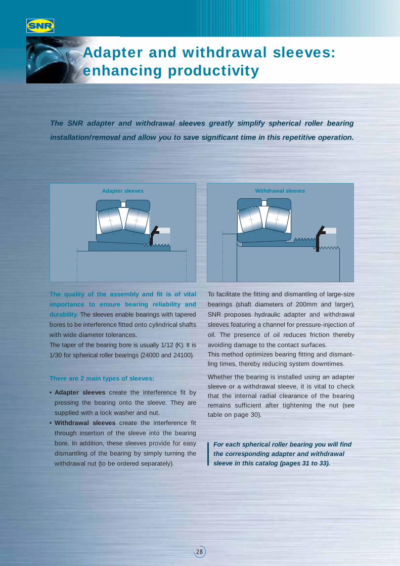
The SNR adapter and withdrawal sleeves greatly simplify spherical roller bearing
installation/removal and allow you to save significant time in this repetitive operation.
The quality of the assembly and fit is of vital
importance to ensure bearing reliability and
durability. The sleeves enable bearings with tapered
bores to be interference fitted onto cylindrical shafts
with wide diameter tolerances.
The taper of the bearing bore is usually 1/12 (K). It is
1/30 for spherical roller bearings (24000 and 24100).
There are 2 main types of sleeves:
• Adapter sleeves create the interference fit by
pressing the bearing onto the sleeve. They are
supplied with a lock washer and nut.
• Withdrawal sleeves create the interference fit
through insertion of the sleeve into the bearing
bore. In addition, these sleeves provide for easy
dismantling of the bearing by simply turning the
withdrawal nut (to be ordered separately).
To facilitate the fitting and dismantling of large-size
bearings (shaft diameters of 200mm and larger),
SNR proposes hydraulic adapter and withdrawal
sleeves featuring a channel for pressure-injection of
oil. The presence of oil reduces friction thereby
avoiding damage to the contact surfaces.
This method optimizes bearing fitting and dismant-
ling times, thereby reducing system downtimes.
Whether the bearing is installed using an adapter
sleeve or a withdrawal sleeve, it is vital to check
that the internal radial clearance of the bearing
remains sufficient after tightening the nut (see
table on page 30).
For each spherical roller bearing you will findthe corresponding adapter and withdrawalsleeve in this catalog (pages 31 to 33).
Adapter sleeves Withdrawal sleeves
29
When fitting the bearing or sleeve, the expansion of the inner ring reduces the internal
radial clearance of the bearing. The reduction in clearance enables the tightness of the
fit to be determined. It is important to check this. Check carefully that the clearance
necessary for the correct functioning of the bearing is maintained.
Reduction of the internal clearance after fitting
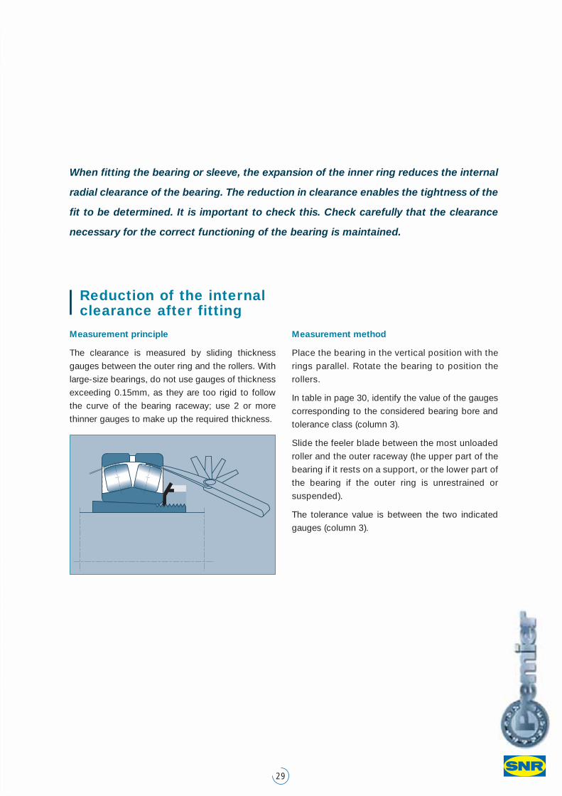
Measurement principle
The clearance is measured by sliding thickness
gauges between the outer ring and the rollers. With
large-size bearings, do not use gauges of thickness
exceeding 0.15mm, as they are too rigid to follow
the curve of the bearing raceway; use 2 or more
thinner gauges to make up the required thickness.
Measurement method
Place the bearing in the vertical position with the
rings parallel. Rotate the bearing to position the
rollers.
In table in page 30, identify the value of the gauges
corresponding to the considered bearing bore and
tolerance class (column 3).
Slide the feeler blade between the most unloaded
roller and the outer raceway (the upper part of the
bearing if it rests on a support, or the lower part of
the bearing if the outer ring is unrestrained or
suspended).
The tolerance value is between the two indicated
gauges (column 3).
Adapter and withdrawal sleeves: enhancing productivity
30
BEFORE FITTING (2) AFTER FITTING (3)
C0 C3 C4 C0 C3 C4
Per ISO Per ISO Per ISO Gauge Gauge Gaugefrom to 5753 5753 5753 to use to use to use
(mm) (mm) (mm)
Bearingbore(mm)
Verification of radial clearance on assembly
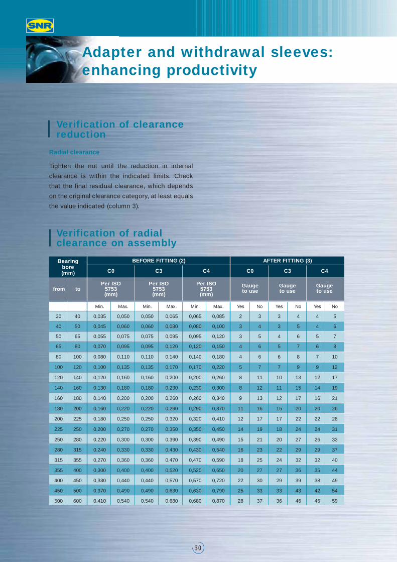
Radial clearance
Tighten the nut until the reduction in internal
clearance is within the indicated limits. Check
that the final residual clearance, which depends
on the original clearance category, at least equals
the value indicated (column 3).
Verification of clearance reduction
Min. Max. Min. Max. Min. Max. Yes No Yes No Yes No
30 40 0,035 0,050 0,050 0,065 0,065 0,085 2 3 3 4 4 5
40 50 0,045 0,060 0,060 0,080 0,080 0,100 3 4 3 5 4 6
50 65 0,055 0,075 0,075 0,095 0,095 0,120 3 5 4 6 5 7
65 80 0,070 0,095 0,095 0,120 0,120 0,150 4 6 5 7 6 8
80 100 0,080 0,110 0,110 0,140 0,140 0,180 4 6 6 8 7 10
100 120 0,100 0,135 0,135 0,170 0,170 0,220 5 7 7 9 9 12
120 140 0,120 0,160 0,160 0,200 0,200 0,260 8 11 10 13 12 17
140 160 0,130 0,180 0,180 0,230 0,230 0,300 8 12 11 15 14 19
160 180 0,140 0,200 0,200 0,260 0,260 0,340 9 13 12 17 16 21
180 200 0,160 0,220 0,220 0,290 0,290 0,370 11 16 15 20 20 26
200 225 0,180 0,250 0,250 0,320 0,320 0,410 12 17 17 22 22 28
225 250 0,200 0,270 0,270 0,350 0,350 0,450 14 19 18 24 24 31
250 280 0,220 0,300 0,300 0,390 0,390 0,490 15 21 20 27 26 33
280 315 0,240 0,330 0,330 0,430 0,430 0,540 16 23 22 29 29 37
315 355 0,270 0,360 0,360 0,470 0,470 0,590 18 25 24 32 32 40
355 400 0,300 0,400 0,400 0,520 0,520 0,650 20 27 27 36 35 44
400 450 0,330 0,440 0,440 0,570 0,570 0,720 22 30 29 39 38 49
450 500 0,370 0,490 0,490 0,630 0,630 0,790 25 33 33 43 42 54
500 600 0,410 0,540 0,540 0,680 0,680 0,870 28 37 36 46 46 59
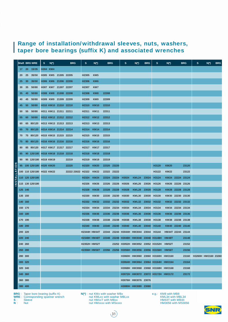
31
Shaft BRG WRE S N(*) BRG S N(*) BRG S N(*) BRG S N(*) BRG S N(*) BRG
17 20 15/35 H304 KM4
20 25 35/50 H305 KM5 21305 22205 H2305 KM5
25 30 35/50 H306 KM6 21306 22206 H2306 KM6
30 35 50/80 H307 KM7 21307 22207 H2307 KM7
35 40 50/80 H308 KM8 21308 22208 H2308 KM8 22308
40 45 50/80 H309 KM9 21309 22209 H2309 KM9 22309
45 50 50/80 H310 KM10 21310 22210 H2310 KM10 22310
50 55 50/80 H311 KM11 21311 22211 H2311 KM11 22311
55 60 50/80 H312 KM12 21312 22212 H2312 KM12 22312
60 65 80/120 H313 KM13 21313 22213 H2313 KM13 22313
65 70 80/120 H314 KM14 21314 22214 H2314 KM14 22314
70 75 80/120 H315 KM15 21315 22215 H2315 KM15 22315
75 80 80/120 H316 KM16 21316 22216 H2316 KM16 22316
80 85 80/120 H317 KM17 21317 22217 H2317 KM17 22317
85 90 120/180 H318 KM18 21318 22218 H2318 KM18 22318
90 95 120/180 H319 KM19 22219 H2319 KM19 22319
95 100 120/180 H320 KM20 22220 H2320 KM20 22320 23220 H3120 KM20 23120
100 110 120/180 H322 KM22 22222 23022 H2322 KM22 22322 23222 H3122 KM22 23122
110 120 120/180 H2324 KM24 22324 23224 H3024 KML24 23024 H3124 KM24 22224 23124
115 130 120/180 H2326 KM26 22326 23226 H3026 KML26 23026 H3126 KM26 22226 23126
125 140 H2328 KM28 22328 23228 H3028 KML28 23028 H3128 KM28 22228 23128
135 150 H2330 KM30 22330 23230 H3030 KML30 23030 H3130 KM30 22230 23130
140 160 H2332 KM32 22332 23232 H3032 KML32 23032 H3132 KM32 22232 23132
150 170 H2334 KM34 22334 23234 H3034 KML34 23034 H3134 KM34 22234 23134
160 180 H2336 KM36 22336 23236 H3036 KML36 23036 H3136 KM36 22236 23136
170 190 H2338 KM38 22338 23238 H3038 KML38 23038 H3138 KM38 22238 23138
180 200 H2340 KM40 22340 23240 H3040 KML40 23040 H3140 KM40 22240 23140
200 220 H2344H HM44T 22344 23244 H3044H HM3044 23044 H3144 HM44T 22244 23144
220 240 H2348H HM48T 22348 23248 H3048H HM3048 23048 H3148H HM48T 23148
240 260 H2352H HM52T 23252 H3052H HM3052 23052 H3152H HM52T 23152
260 280 H2356H HM56T 22356 23256 H3056H HM3056 23056 H3156H HM56T 23156
280 300 H3060H HM3060 23060 H3160H HM3160 23160 H3260H HM3160 23260
300 320 H3064H HM3064 23064 H3164H HM3164 23164
320 340 H3068H HM3068 23068 H3168H HM3168 23168
340 360 H3072H HM3072 23072 H3172H HM3172 23172
360 380 H3076H HM3076 23076
380 400 H3080H HM3080 23080
INS
TA
LL
AT
ION
Range of installation/withdrawal sleeves, nuts, washers,taper bore bearings (suffix K) and associated wrenches
BRG : Taper bore bearing (suffix K)WRE : Corresponding spanner wrench S : SleeveN : Nut
N(*) : nut KMx with washer MBx nut KMLxx with washer MBLxx nut HMxxT with MBxx nut HMxxxx with MSxxxx
e.g.: KM8 with MB8KML34 with MBL34HM44T with MB44 HM3056 with MS3056
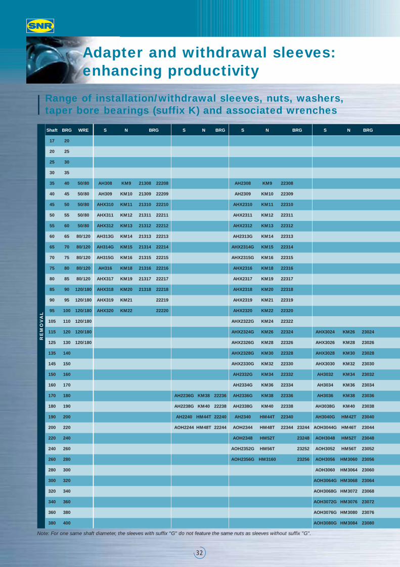
Adapter and withdrawal sleeves: enhancing productivity
32
Shaft BRG WRE S N BRG S N BRG S N BRG S N BRG
17 20
20 25
25 30
30 35
35 40 50/80 AH308 KM9 21308 22208 AH2308 KM9 22308
40 45 50/80 AH309 KM10 21309 22209 AH2309 KM10 22309
45 50 50/80 AHX310 KM11 21310 22210 AHX2310 KM11 22310
50 55 50/80 AHX311 KM12 21311 22211 AHX2311 KM12 22311
55 60 50/80 AHX312 KM13 21312 22212 AHX2312 KM13 22312
60 65 80/120 AH313G KM14 21313 22213 AH2313G KM14 22313
65 70 80/120 AH314G KM15 21314 22214 AHX2314G KM15 22314
70 75 80/120 AH315G KM16 21315 22215 AHX2315G KM16 22315
75 80 80/120 AH316 KM18 21316 22216 AHX2316 KM18 22316
80 85 80/120 AHX317 KM19 21317 22217 AHX2317 KM19 22317
85 90 120/180 AHX318 KM20 21318 22218 AHX2318 KM20 22318
90 95 120/180 AHX319 KM21 22219 AHX2319 KM21 22319
95 100 120/180 AHX320 KM22 22220 AHX2320 KM22 22320
105 110 120/180 AHX2322G KM24 22322
115 120 120/180 AHX2324G KM26 22324 AHX3024 KM26 23024
125 130 120/180 AHX2326G KM28 22326 AHX3026 KM28 23026
135 140 AHX2328G KM30 22328 AHX3028 KM30 23028
145 150 AHX2330G KM32 22330 AHX3030 KM32 23030
150 160 AH2332G KM34 22332 AH3032 KM34 23032
160 170 AH2334G KM36 22334 AH3034 KM36 23034
170 180 AH2236G KM38 22236 AH2336G KM38 22336 AH3036 KM38 23036
180 190 AH2238G KM40 22238 AH2338G KM40 22338 AH3038G KM40 23038
190 200 AH2240 HM44T 22240 AH2340 HM44T 22340 AH3040G HM42T 23040
200 220 AOH2244 HM48T 22244 AOH2344 HM48T 22344 23244 AOH3044G HM46T 23044
220 240 AOH2348 HM52T 23248 AOH3048 HM52T 23048
240 260 AOH2352G HM56T 23252 AOH3052 HM56T 23052
260 280 AOH2356G HM3160 23256 AOH3056 HM3060 23056
280 300 AOH3060 HM3064 23060
300 320 AOH3064G HM3068 23064
320 340 AOH3068G HM3072 23068
340 360 AOH3072G HM3076 23072
360 380 AOH3076G HM3080 23076
380 400 AOH3080G HM3084 23080
RE
MO
VA
L
Note: For one same shaft diameter, the sleeves with suffix "G" do not feature the same nuts as sleeves without suffix "G".
Range of installation/withdrawal sleeves, nuts, washers,taper bore bearings (suffix K) and associated wrenches
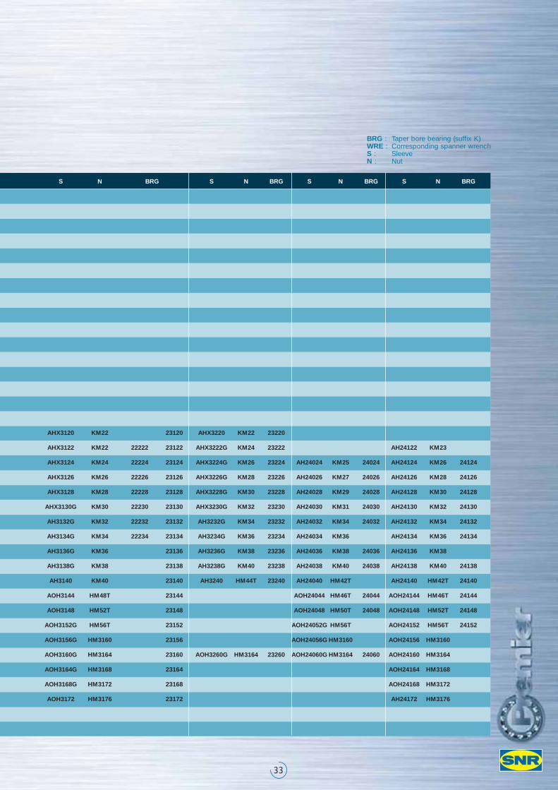
33
S N BRG S N BRG S N BRG S N BRG
AHX3120 KM22 23120 AHX3220 KM22 23220
AHX3122 KM22 22222 23122 AHX3222G KM24 23222 AH24122 KM23
AHX3124 KM24 22224 23124 AHX3224G KM26 23224 AH24024 KM25 24024 AH24124 KM26 24124
AHX3126 KM26 22226 23126 AHX3226G KM28 23226 AH24026 KM27 24026 AH24126 KM28 24126
AHX3128 KM28 22228 23128 AHX3228G KM30 23228 AH24028 KM29 24028 AH24128 KM30 24128
AHX3130G KM30 22230 23130 AHX3230G KM32 23230 AH24030 KM31 24030 AH24130 KM32 24130
AH3132G KM32 22232 23132 AH3232G KM34 23232 AH24032 KM34 24032 AH24132 KM34 24132
AH3134G KM34 22234 23134 AH3234G KM36 23234 AH24034 KM36 AH24134 KM36 24134
AH3136G KM36 23136 AH3236G KM38 23236 AH24036 KM38 24036 AH24136 KM38
AH3138G KM38 23138 AH3238G KM40 23238 AH24038 KM40 24038 AH24138 KM40 24138
AH3140 KM40 23140 AH3240 HM44T 23240 AH24040 HM42T AH24140 HM42T 24140
AOH3144 HM48T 23144 AOH24044 HM46T 24044 AOH24144 HM46T 24144
AOH3148 HM52T 23148 AOH24048 HM50T 24048 AOH24148 HM52T 24148
AOH3152G HM56T 23152 AOH24052G HM56T AOH24152 HM56T 24152
AOH3156G HM3160 23156 AOH24056G HM3160 AOH24156 HM3160
AOH3160G HM3164 23160 AOH3260G HM3164 23260 AOH24060G HM3164 24060 AOH24160 HM3164
AOH3164G HM3168 23164 AOH24164 HM3168
AOH3168G HM3172 23168 AOH24168 HM3172
AOH3172 HM3176 23172 AH24172 HM3176
BRG : Taper bore bearing (suffix K)WRE : Corresponding spanner wrench S : SleeveN : Nut
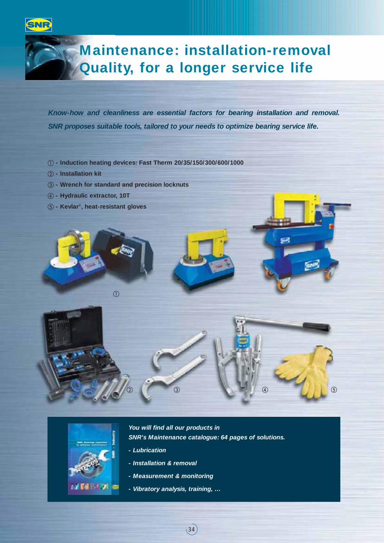
Maintenance: installation-removalQuality, for a longer service life
34
Know-how and cleanliness are essential factors for bearing installation and removal.
SNR proposes suitable tools, tailored to your needs to optimize bearing service life.
� - Induction heating devices: Fast Therm 20/35/150/300/600/1000
� - Installation kit
� - Wrench for standard and precision locknuts
� - Hydraulic extractor, 10T
� - Kevlar®‚ heat-resistant gloves
You will find all our products in
SNR's Maintenance catalogue: 64 pages of solutions.
- Lubrication
- Installation & removal
- Measurement & monitoring
- Vibratory analysis, training, …
�
� � � �
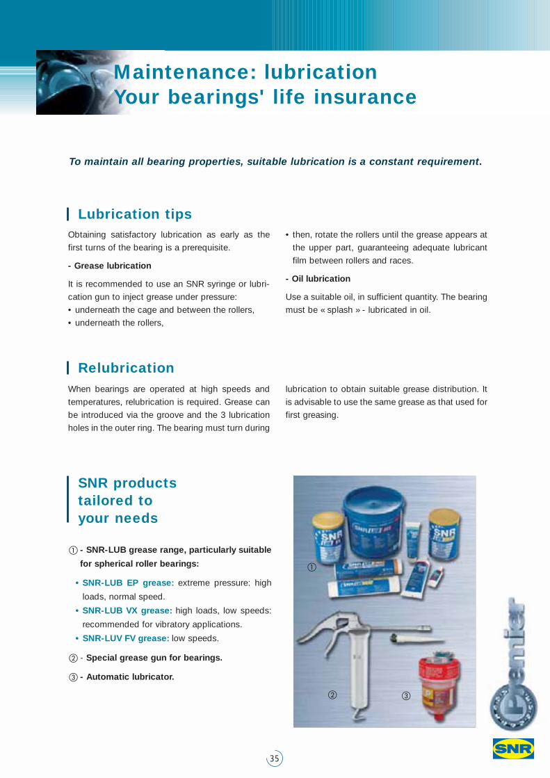
Maintenance: lubrication Your bearings' life insurance
35
� - SNR-LUB grease range, particularly suitable
for spherical roller bearings:
• SNR-LUB EP grease: extreme pressure: high
loads, normal speed.
• SNR-LUB VX grease: high loads, low speeds:
recommended for vibratory applications.
• SNR-LUV FV grease: low speeds.
� - Special grease gun for bearings.
� - Automatic lubricator.
To maintain all bearing properties, suitable lubrication is a constant requirement.
Relubrication
SNR products tailored to your needs
When bearings are operated at high speeds and
temperatures, relubrication is required. Grease can
be introduced via the groove and the 3 lubrication
holes in the outer ring. The bearing must turn during
lubrication to obtain suitable grease distribution. It
is advisable to use the same grease as that used for
first greasing.
Obtaining satisfactory lubrication as early as the
first turns of the bearing is a prerequisite.
- Grease lubrication
It is recommended to use an SNR syringe or lubri-
cation gun to inject grease under pressure:
• underneath the cage and between the rollers,
• underneath the rollers,
• then, rotate the rollers until the grease appears at
the upper part, guaranteeing adequate lubricant
film between rollers and races.
- Oil lubrication
Use a suitable oil, in sufficient quantity. The bearing
must be « splash » - lubricated in oil.
Lubrication tips
�
� �
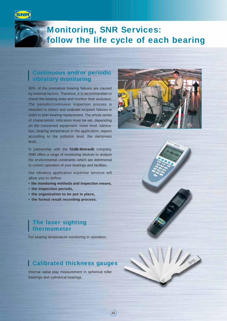
Monitoring, SNR Services: follow the life cycle of each bearing
36
Calibrated thickness gaugesInternal radial play measurement in spherical roller
bearings and cylindrical bearings.
The laser sighting thermometer
For bearing temperature monitoring in operation.
Continuous and/or periodicvibratory monitoring
90% of the premature bearing failures are caused
by external factors. Therefore, it is recommended to
check the bearing state and monitor their evolution.
The periodic/continuous inspection process is
intended to detect and evaluate incipient failures in
order to plan bearing replacement. The whole series
of characteristic indicators must be set, depending
on the concerned equipment: noise level, lubrica-
tion, bearing temperature in the application, aspect
according to the pollution level, the dampness
level, …
In partnership with the 01dB-Metravib company,
SNR offers a range of monitoring devices to analyze
the environmental constraints which are detrimental
to correct operation of your bearings and facilities.
Our vibratory application expertise services will
allow you to define:
• the monitoring methods and inspection means,• the inspection periods,• the organization to be put in place,• the formal result recording process.
37
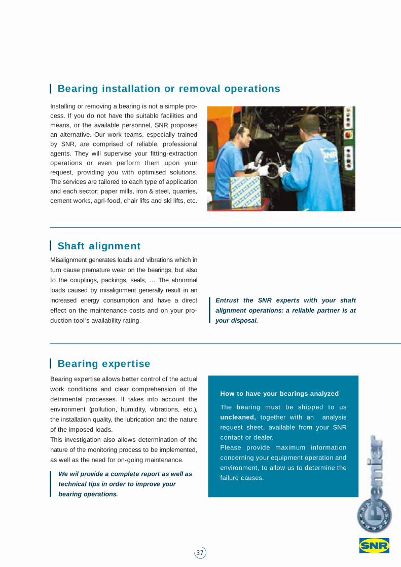
Bearing installation or removal operations
Installing or removing a bearing is not a simple pro-
cess. If you do not have the suitable facilities and
means, or the available personnel, SNR proposes
an alternative. Our work teams, especially trained
by SNR, are comprised of reliable, professional
agents. They will supervise your fitting-extraction
operations or even perform them upon your
request, providing you with optimised solutions.
The services are tailored to each type of application
and each sector: paper mills, iron & steel, quarries,
cement works, agri-food, chair lifts and ski lifts, etc.
Misalignment generates loads and vibrations which in
turn cause premature wear on the bearings, but also
to the couplings, packings, seals, … The abnormal
loads caused by misalignment generally result in an
increased energy consumption and have a direct
effect on the maintenance costs and on your pro-
duction tool's availability rating.
Entrust the SNR experts with your shaft
alignment operations: a reliable partner is at
your disposal.
Bearing expertiseBearing expertise allows better control of the actual
work conditions and clear comprehension of the
detrimental processes. It takes into account the
environment (pollution, humidity, vibrations, etc.),
the installation quality, the lubrication and the nature
of the imposed loads.
This investigation also allows determination of the
nature of the monitoring process to be implemented,
as well as the need for on-going maintenance.
We wil provide a complete report as well as
technical tips in order to improve your
bearing operations.
Shaft alignment
How to have your bearings analyzed
The bearing must be shipped to us
uncleaned, together with an analysis
request sheet, available from your SNR
contact or dealer.
Please provide maximum information
concerning your equipment operation and
environment, to allow us to determine the
failure causes.
Optimize each product to achieve the greatest performance possible, without increasing prices:
this is a leading manufacturer's mission. The Premier quality approach essentially addresses the
family of spherical bearings and allows us to appreciably optimize our product range in the four
main categories effecting reliability and service life: steel selection, internal geometry, lubrication /
sealing, and finishing.
Siège social : SNR ROULEMENTS - Rue des Usines - 74000 Annecy - FRANCE - RCS Annecy B 325821072 - Code NAF 291H
www.snr-bearings.com
DO
C.I_
SP
HE
R_C
AT1.
GB
a -
Non
con
trac
tual
doc
umen
t -
SN
R c
opyr
ight
inte
rnat
iona
l 03/
2005
- P
rinte
d in
Fra
nce
- P
hoto
s :
Sém
apho
re -
Del
phi
s -
SN
R
www.snr-contact.com
A U T O M O T I V E / A E R O S P A C E / I N D U S T R Y
Spherical roller bearings: choose Premier to benefit from SNR's entire expertise