Embed Size (px)
DESCRIPTION
Nature of Bearing Failures
Citation preview
Premature bearing failures in industrial gearboxes
Lagerfrühausfälle in Industriegetrieben
Kenred Stadler°
Arno Stubenrauch*
SKF GmbH, Gunnar-Wester-Str. 12, 97421 Schweinfurt, Germany
Tel: +49 9721562854, Fax: +49 97215662854
Tel: +49 9721 56 2335, Fax: +49 9721 56 3256

Premature Bearing Failures
Content / Inhaltsverzeichnis
1 Abstract................................................................................................................ 2
2 Introduction ......................................................................................................... 2
3 Challenges due to operating conditions in wind turbine gearboxes ............. 5
4 Possible “crack” drivers and review of hypotheses........................................ 7
5 Potential root cause of WEC’s in wind gearboxes according to SKF experience ........................................................................................................... 8
6 Potential mechanism for damage propagation .............................................. 11
7 Conclusion and SKF prevention strategy ....................................................... 14
8 References......................................................................................................... 16
ATK 2013
1 Abstract
Bearings in large industrial gearboxes or drive train applications, such as paper mills, crusher mill gearboxes, lifting gear drives or especially in wind turbine gearboxes are often subjected to a wide variety of operating conditions that may push them beyond their limits under certain circumstances.
Damage may be done to the bearings, resulting in a failure mode that is not described in ISO 15243, known as white etching cracks (WEC) or sometimes called white structure flaking (WSF).
Known to occur occasionally in some industrial applications mentioned above, in wind applications the premature failure mode seems to be more prevalent.
In this paper, a hypothesis of the root causes of WEC will be presented. Measures to make the bearings more resistant in these applications are also discussed.
2 Introduction
Many industrial gearboxes, such as wind turbine gearboxes are subjected to a wide variety of operating conditions, some of which may push the bearings beyond their limits. However, it is neither completely known which of the conditions is relevant nor where the limits of individual bearing executions are. Damage may be done to the bearings resulting in a specific premature failure mode known as White Etching Cracks (WEC), sometimes called brittle, short-life, early, abnormal or White Structure Flaking (WSF).
Ambitious worldwide renewable energy targets are pushing wind energy to become a mainstream power source. For example, GWEC1 expects that the presently installed wind energy capacity of 200 GW will double within three to four years, keeping open the aspiration goal of 1,000 GW of installed capacity by 2020.
Despite high wind turbine availability (> 96%, depending on turbine), and a relatively low failure rate of mechanical components compared to electrical components, failures of mechanical components in drive trains often create high repair costs and revenue loss due to long down times2.
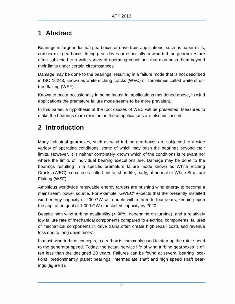
In most wind turbine concepts, a gearbox is commonly used to step-up the rotor speed to the generator speed. Today, the actual service life of wind turbine gearboxes is often less than the designed 20 years. Failures can be found at several bearing locations, predominantly planet bearings, intermediate shaft and high speed shaft bearings (figure 1).
2
Premature Bearing Failures
Figure 1: Standard Multi Megawatt (MMW) wind gearbox (for 3-point-suspension) having a low speed planet stage and two spur wheel sections (high intermediate speed shaft and high speed shaft) with highlighted bearing
locations that can be affected by premature bearing failures.
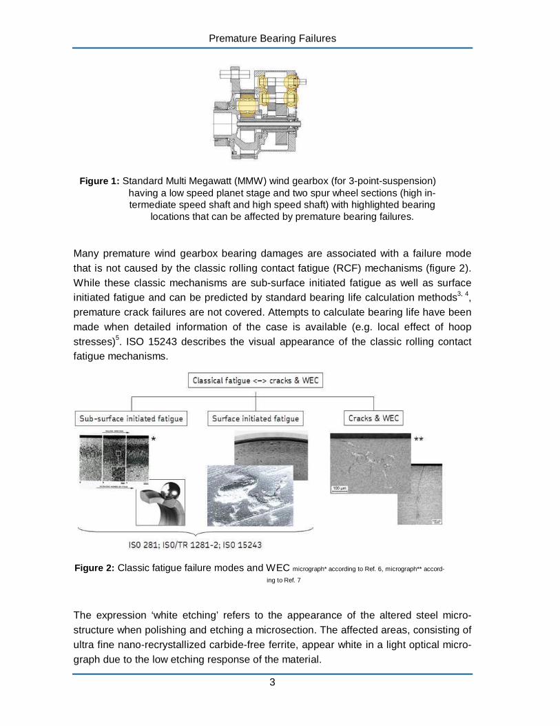
Many premature wind gearbox bearing damages are associated with a failure mode that is not caused by the classic rolling contact fatigue (RCF) mechanisms (figure 2). While these classic mechanisms are sub-surface initiated fatigue as well as surface initiated fatigue and can be predicted by standard bearing life calculation methods3, 4 , premature crack failures are not covered. Attempts to calculate bearing life have been made when detailed information of the case is available (e.g. local effect of hoop stresses)5. ISO 15243 describes the visual appearance of the classic rolling contact fatigue mechanisms.
Figure 2: Classic fatigue failure modes and WEC micrograph* according to Ref. 6, micrograph** accord
ing to Ref. 7
The expression ‘white etching’ refers to the appearance of the altered steel microstructure when polishing and etching a microsection. The affected areas, consisting of ultra fine nano-recrystallized carbide-free ferrite, appear white in a light optical micrograph due to the low etching response of the material.
3
ATK 2013
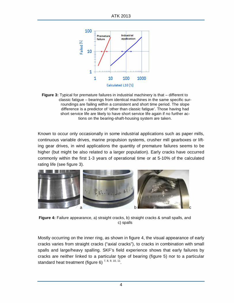
Figure 3: Typical for premature failures in industrial machinery is that – different to classic fatigue – bearings from identical machines in the same specific surroundings are failing within a consistent and short time period. The slope difference is a predictor of ‘other than classic fatigue’. Those having had short service life are likely to have short service life again if no further ac
tions on the bearing-shaft-housing system are taken.
Known to occur only occasionally in some industrial applications such as paper mills, continuous variable drives, marine propulsion systems, crusher mill gearboxes or lifting gear drives, in wind applications the quantity of premature failures seems to be higher (but might be also related to a larger population). Early cracks have occurred commonly within the first 1-3 years of operational time or at 5-10% of the calculated rating life (see figure 3).
a b c
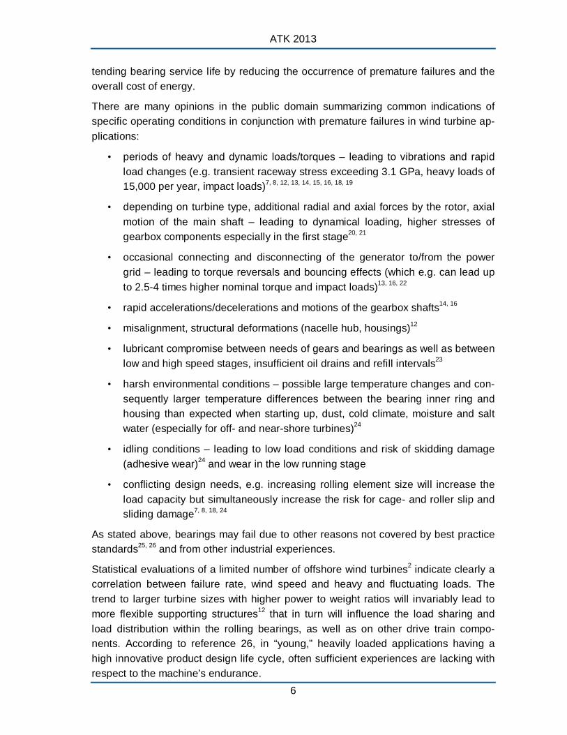
Figure 4: Failure appearance, a) straight cracks, b) straight cracks & small spalls, and c) spalls
Mostly occurring on the inner ring, as shown in figure 4, the visual appearance of early cracks varies from straight cracks (“axial cracks”), to cracks in combination with small spalls and large/heavy spalling. SKF’s field experience shows that early failures by cracks are neither linked to a particular type of bearing (figure 5) nor to a particular standard heat treatment (figure 6) 7, 8, 9, 10, 11 .
4

Premature Bearing Failures
a b c
Figure 5: Examples of typical bearing types that can be affected, a) tapered roller bearing, b) cylindrical roller bearing, and c) spherical roller bearing
The failure appearance however is associated with the heat treatment (e.g. by the residual stress field), how far the failure has progressed and very likely also with the operating condition or bearing position (e.g. stress field from loading). As it can be seen in figure 6, for early cracking in this specific application, cracks in martensite rings tend to grow straight into the material (suggesting the straight “axial” crack appearance, e.g. figure 6a), whereas in bainitic (figure 6b) as well as in carburized case hardened rings, the cracks tend to grow circumferentially below the raceway (explaining the spall/flaking type of appearance, e.g. figure 6c). Nevertheless, in a very advanced failure stage, the inner ring raceways are often heavily spalled, independent of the heat treatment.
b
a c
Figure 6: Crack growth patterns in standard heat treatments, a) martensite, b) bainitic, and c) case hardened (case carburized)7
3 Challenges due to operating conditions in wind turbine gearboxes
Wind turbine gearboxes are subjected to a wide variety of operating conditions that may push the bearings beyond their limits (e.g. with respect to load, speed, lubrication and combinations of it). The wind energy segment faces the challenge between ex
5
ATK 2013
tending bearing service life by reducing the occurrence of premature failures and the overall cost of energy.
There are many opinions in the public domain summarizing common indications of specific operating conditions in conjunction with premature failures in wind turbine applications:
• periods of heavy and dynamic loads/torques – leading to vibrations and rapid load changes (e.g. transient raceway stress exceeding 3.1 GPa, heavy loads of 15,000 per year, impact loads)7, 8, 12, 13, 14, 15, 16, 18, 19
• depending on turbine type, additional radial and axial forces by the rotor, axial motion of the main shaft – leading to dynamical loading, higher stresses of gearbox components especially in the first stage20, 21
• occasional connecting and disconnecting of the generator to/from the power grid – leading to torque reversals and bouncing effects (which e.g. can lead up to 2.5-4 times higher nominal torque and impact loads)13, 16, 22
• rapid accelerations/decelerations and motions of the gearbox shafts14, 16
• misalignment, structural deformations (nacelle hub, housings)12
• lubricant compromise between needs of gears and bearings as well as between low and high speed stages, insufficient oil drains and refill intervals23
• harsh environmental conditions – possible large temperature changes and consequently larger temperature differences between the bearing inner ring and housing than expected when starting up, dust, cold climate, moisture and salt water (especially for off- and near-shore turbines)24
• idling conditions – leading to low load conditions and risk of skidding damage (adhesive wear)24 and wear in the low running stage
• conflicting design needs, e.g. increasing rolling element size will increase the load capacity but simultaneously increase the risk for cage- and roller slip and sliding damage7, 8, 18, 24
As stated above, bearings may fail due to other reasons not covered by best practice standards25, 26 and from other industrial experiences.
Statistical evaluations of a limited number of offshore wind turbines2 indicate clearly a correlation between failure rate, wind speed and heavy and fluctuating loads. The trend to larger turbine sizes with higher power to weight ratios will invariably lead to more flexible supporting structures12 that in turn will influence the load sharing and load distribution within the rolling bearings, as well as on other drive train components. According to reference 26, in “young,” heavily loaded applications having a high innovative product design life cycle, often sufficient experiences are lacking with respect to the machine’s endurance.
6
Premature Bearing Failures
Independent from the opinion of wind turbine and gearbox manufacturers, in 20 & 28 the presence of cracks on bearings is sometimes interpreted as indicative of uncontrolled kinematic behavior, without specifying the kinematics.
4 Possible “crack” drivers and review of hypotheses
The occurrence of premature failures is heavily discussed within the wind industry and independently investigated by wind turbine manufacturers, gearbox manufacturers, bearing suppliers as well as universities and independent institutes. Unfortunately, a consistent theory does not exist today. To list and explain all WEC failure root cause hypotheses would go beyond the scope of this paper.
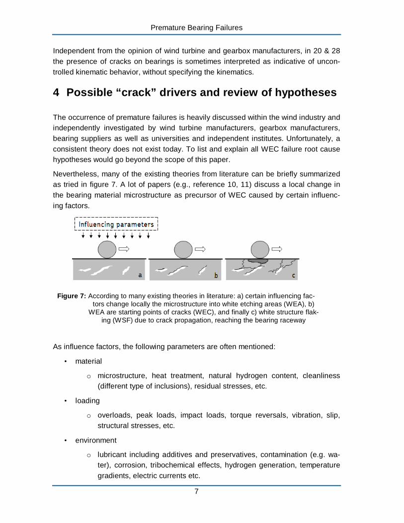
Nevertheless, many of the existing theories from literature can be briefly summarized as tried in figure 7. A lot of papers (e.g., reference 10, 11) discuss a local change in the bearing material microstructure as precursor of WEC caused by certain influencing factors.
Figure 7: According to many existing theories in literature: a) certain influencing factors change locally the microstructure into white etching areas (WEA), b)
WEA are starting points of cracks (WEC), and finally c) white structure flaking (WSF) due to crack propagation, reaching the bearing raceway
As influence factors, the following parameters are often mentioned:
• material
o microstructure, heat treatment, natural hydrogen content, cleanliness (different type of inclusions), residual stresses, etc.
• loading
o overloads, peak loads, impact loads, torque reversals, vibration, slip, structural stresses, etc.
• environment
o lubricant including additives and preservatives, contamination (e.g. water), corrosion, tribochemical effects, hydrogen generation, temperature gradients, electric currents etc.
7
ATK 2013
• others
o improper mounting, transport damage, quality aspects, etc.
Things are getting even more complex as most influencing factors are correlated.
Thus, driven by a single factor or by a combination of several factors, WEA develop locally in the bearing steel matrix. The WEA will then be the nucleation sites of cracks that finally propagate to the bearing raceway. As a consequence, the bearing is failing by spalling or so-called WSF.
Most common hypotheses can be further divided into hydrogen enhanced WEC developments29, 30, 31 , purely load/stress related WEC developments preferable at inclusions32, 33, or combinations of reasons 34.
Some of the above mentioned damage mechanisms seem provide the explanation for successful solutions in applications others than wind:
• paper mills (e.g. water in oil – corrective action based on condition of lubrication)35
• marine propulsion systems (e.g. exceeding stresses – corrective action based on special through hardened clean steel and stress reduction)33, 35
• alternator and generator bearings (e.g. damaging current – corrective action by use of special greases and/or hybrid bearings, special steels)7, 36, 37
Anyway, the relevance of the common WEC hypotheses for premature wind gearbox failures is not sufficiently clear yet.
5 Potential root cause of WEC’s in wind gearboxes according to SKF experience
To artificially generate WEC in components or bearings is not a big challenge. However, the relevance of certain WEC tests can be questioned if test conditions deviate from field conditions.
According to SKF’s experience, most early bearing failures are related to lubrication or other surface related issues. SKF internal investigations have revealed that many cracking failure modes in wind gearbox bearing positions most likely have their origin at or near the surface and propagate into the material under the influence of a corrosion fatigue process7, 8, 17 .
There are several indicators that can support this hypothesis:
Wind gearbox bearings are relatively large. For larger bearings, the crack initiation and propagation mechanism can differ compared to small bearings7, 17. For instance, a
8
Premature Bearing Failures
deeper radial crack is reported in larger bearings at moderate loads due to the residual stresses and higher hoop stress5.
In case of premature wind gearbox bearing failures, the failure occurrence suggests fast crack propagation. The fast branching and spreading crack propagation can be explained by the presence of chemical influencing factors such as oxygen and aging products of the lubricant (via EDX analysis) at the crack faces/tips 7, 17, 38. In a completely sub-surface crack system, there are vacuum conditions and consequently significant slower crack growth from pure mechanical fatigue38. In other words, already at an early stage, the cracks or crack systems must be connected to the surface to allow the entrance of oxygen and lubricant.
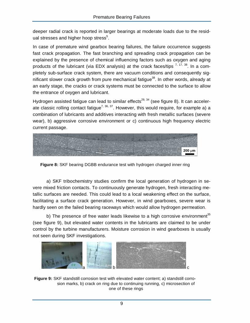
Hydrogen assisted fatigue can lead to similar effects29, 34 (see figure 8). It can accelerate classic rolling contact fatigue7, 36, 37. However, this would require, for example a) a combination of lubricants and additives interacting with fresh metallic surfaces (severe wear), b) aggressive corrosive environment or c) continuous high frequency electric current passage.
200 μm
Figure 8: SKF bearing DGBB endurance test with hydrogen charged inner ring
a) SKF tribochemistry studies confirm the local generation of hydrogen in severe mixed friction contacts. To continuously generate hydrogen, fresh interacting metallic surfaces are needed. This could lead to a local weakening effect on the surface, facilitating a surface crack generation. However, in wind gearboxes, severe wear is hardly seen on the failed bearing raceways which would allow hydrogen permeation.
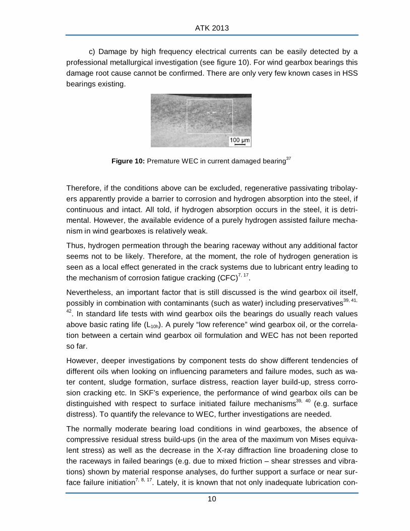
b) The presence of free water leads likewise to a high corrosive environment35
(see figure 9), but elevated water contents in the lubricants are claimed to be under control by the turbine manufacturers. Moisture corrosion in wind gearboxes is usually not seen during SKF investigations.
a b c
Figure 9: SKF standstill corrosion test with elevated water content; a) standstill corrosion marks, b) crack on ring due to continuing running, c) microsection of
one of these rings
9
ATK 2013
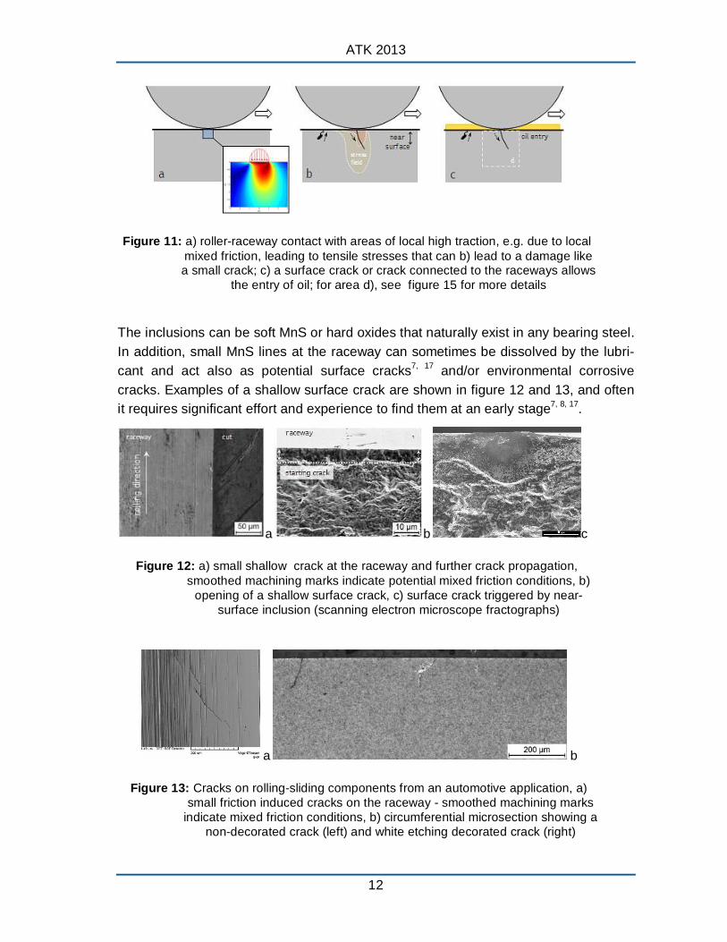
c) Damage by high frequency electrical currents can be easily detected by a professional metallurgical investigation (see figure 10). For wind gearbox bearings this damage root cause cannot be confirmed. There are only very few known cases in HSS bearings existing.
Figure 10: Premature WEC in current damaged bearing37
Therefore, if the conditions above can be excluded, regenerative passivating tribolayers apparently provide a barrier to corrosion and hydrogen absorption into the steel, if continuous and intact. All told, if hydrogen absorption occurs in the steel, it is detrimental. However, the available evidence of a purely hydrogen assisted failure mechanism in wind gearboxes is relatively weak.
Thus, hydrogen permeation through the bearing raceway without any additional factor seems not to be likely. Therefore, at the moment, the role of hydrogen generation is seen as a local effect generated in the crack systems due to lubricant entry leading to the mechanism of corrosion fatigue cracking (CFC)7, 17 .
Nevertheless, an important factor that is still discussed is the wind gearbox oil itself, possibly in combination with contaminants (such as water) including preservatives39, 41,
42. In standard life tests with wind gearbox oils the bearings do usually reach values above basic rating life (L10h). A purely “low reference” wind gearbox oil, or the correlation between a certain wind gearbox oil formulation and WEC has not been reported so far.
However, deeper investigations by component tests do show different tendencies of different oils when looking on influencing parameters and failure modes, such as water content, sludge formation, surface distress, reaction layer build-up, stress corrosion cracking etc. In SKF’s experience, the performance of wind gearbox oils can be distinguished with respect to surface initiated failure mechanisms39, 40 (e.g. surface distress). To quantify the relevance to WEC, further investigations are needed.
The normally moderate bearing load conditions in wind gearboxes, the absence of compressive residual stress build-ups (in the area of the maximum von Mises equivalent stress) as well as the decrease in the X-ray diffraction line broadening close to the raceways in failed bearings (e.g. due to mixed friction – shear stresses and vibrations) shown by material response analyses, do further support a surface or near surface failure initiation7, 8, 17. Lately, it is known that not only inadequate lubrication con
10

Premature Bearing Failures
ditions, but also certain vibration effects at higher frequencies, are able to reduce the film thickness and consequently increase the risk for conditions of local mixed friction43, 44 .
Reference 44 confirms SKF experience that the generation of WEC networks is less influenced by Hertzian pressures and that the most influencing factors are surface based. The often disputed role of butterfly crack generation at inclusions, which show a similar altered microstructure as seen in WEC, is considered as part of the classic fatigue mechanism that is well covered in the bearing life model8, 45, 46. Little experimental evidence is reported that supports butterfly cracks propagating into WEC networks 11.
A high butterfly density is a sign of overstress or very heavy loading (>2-3 GPa), but excessive overloads are - by turbine manufacturers - claimed to not exist. This seems to be supported by standard gearbox HALT tests. A highly accelerated life test (HALT) is a stress testing methodology to demonstrate reliability by accelerated tesing during the engineering development process. There, the metallurgical investigations do often show an elevated number of butterfly formations in the bearings due to heavy load test conditions, but failed bearings from the field often do not show a significant increase in butterfly formations7, 8. Especially at the high speed stages, the loads are usually moderate, but bearings can still fail by cracks / WEC without showing a significant population or even individual examples of butterflies7, 8. It seems that current standard gearbox HALT tests do need further adaptations to reflect the early failure mechanisms as seen in the field.
6 Potential mechanism for damage propagation
There is some agreement that not nominal wind gearbox operating conditions but rather transient, partly maybe unknown, conditions can occasionally lead to disturbed bearing kinematics, unfavorable loading and insufficient lubrication. Basically, it is assumed that high surface stress concentrations can be reached, e.g. by vibration induced local mixed friction7, 17, 48, misalignment or other events as mentioned above. At boundary lubricated patches at asperity level, the stress concentration of the tensile stresses can increase and open a crack under repeated cycles (areas of high stresses just below the roughness)49, 50 .
As schematically shown in figure 11, transient conditions can trigger cracks in the surface region, possibly accelerated by tribochemical effects7, 17, 39, 41, 42, or sub-surface cracks that reach the raceway when starting at weak points such as inclusions close to the surface7.
11
ATK 2013
Figure 11: a) roller-raceway contact with areas of local high traction, e.g. due to local mixed friction, leading to tensile stresses that can b) lead to a damage like a small crack; c) a surface crack or crack connected to the raceways allows
the entry of oil; for area d), see figure 15 for more details
The inclusions can be soft MnS or hard oxides that naturally exist in any bearing steel. In addition, small MnS lines at the raceway can sometimes be dissolved by the lubricant and act also as potential surface cracks7, 17 and/or environmental corrosive cracks. Examples of a shallow surface crack are shown in figure 12 and 13, and often it requires significant effort and experience to find them at an early stage7, 8, 17 .
a b c
Figure 12: a) small shallow crack at the raceway and further crack propagation, smoothed machining marks indicate potential mixed friction conditions, b)
opening of a shallow surface crack, c) surface crack triggered by near-surface inclusion (scanning electron microscope fractographs)
a b
Figure 13: Cracks on rolling-sliding components from an automotive application, a) small friction induced cracks on the raceway - smoothed machining marks
indicate mixed friction conditions, b) circumferential microsection showing a non-decorated crack (left) and white etching decorated crack (right)
12

Premature Bearing Failures
The cracks shown in figures 13 & 14 are generated in an automotive rolling-sliding contact at high traction and contact pressures, similar to potential critical wind load situations (short term events) of around 3 GPa19.
Figure 14: Opened fracture face (cf. Fig. 13a) revealing two cracks (similar to Fig. 12c), surrounded by the CFC structure (scanning electron microscope frac
tograph, backscattered electron mode)
Once the bearing raceway is locally damaged, the highly EP/AW doped lubricant will penetrate into the crack. Depending on the crack orientation, hydraulic effects will additionally push the crack propagation47. As indicated in figure 15, the lubricant (often aged and/or contaminated with water) will react inside the material at the fresh metallic crack flanks. In other words, a corrosion fatigue crack propagation process, CFC, is triggered.
Figure 15: d) after penetration, oil and additives react in the crack flanks locally producing hydrogen, e) and f) the hydrogen transforms locally the microstructure close to the crack system into White Etching Cracks WEC (from dark
etching regions, DER, to white etching areas, WEA) 7, 8, 17
This leads to a hydrogen induced microstructure transformation by means of hydrogen release from decomposition products of the penetrating oil (additives, contaminants) on the rubbing blank metal crack faces that in turn further accelerate the crack propagation7, 8, 17. This conclusion is also supported by spatially resolved determinations of the hydrogen content in damaged bearing rings which confirm that hydrogen absorption occurs late in the damage process8, 17 .
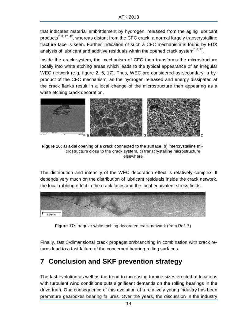
As shown in figure 16, a fractographic investigation in the preparative opened forced fracture face close to the inner ring crack reveals an intercrystalline microstructure
13
ATK 2013
that indicates material embrittlement by hydrogen, released from the aging lubricant products7, 8, 17, 42, whereas distant from the CFC crack, a normal largely transcrystalline fracture face is seen. Further indication of such a CFC mechanism is found by EDX analysis of lubricant and additive residuals within the opened crack system7, 8, 17 .
Inside the crack system, the mechanism of CFC then transforms the microstructure locally into white etching areas which leads to the typical appearance of an irregular WEC network (e.g. figure 2, 6, 17). Thus, WEC are considered as secondary; a by-product of the CFC mechanism, as the hydrogen released and energy dissipated at the crack flanks result in a local change of the microstructure then appearing as a white etching crack decoration.
a b c
Figure 16: a) axial opening of a crack connected to the surface, b) intercrystalline microstructure close to the crack system, c) transcrystalline microstructure
elsewhere
The distribution and intensity of the WEC decoration effect is relatively complex. It depends very much on the distribution of lubricant residuals inside the crack network, the local rubbing effect in the crack faces and the local equivalent stress fields.
Figure 17: Irregular white etching decorated crack network (from Ref. 7)
Finally, fast 3-dimensional crack propagation/branching in combination with crack returns lead to a fast failure of the concerned bearing rolling surfaces.
7 Conclusion and SKF prevention strategy
The fast evolution as well as the trend to increasing turbine sizes erected at locations with turbulent wind conditions puts significant demands on the rolling bearings in the drive train. One consequence of this evolution of a relatively young industry has been premature gearboxes bearing failures. Over the years, the discussion in the industry
14
Premature Bearing Failures
was mainly focused on the influence of bearing material and heat treatments. Recently, there is some agreement that specific wind conditions can lead to disturbed bearing kinematics, loading and lubrication. In other words, the failure root cause cannot be explained by bearing internal parameters only. The complete application interfaces between the bearing and the gearbox / turbine need to be considered.
The phenomenon of wind gearbox bearing failures by cracks / WEC has been described. A failure hypothesis has been introduced. SKF investigations reveal that cracking failure modes in critical wind gearbox bearing positions most likely have their origin at the surface or near surface and propagate further into the material under the influence of a corrosion fatigue process.
Due to the high complexity of a wind turbine as well as the very different bearing locations that can be affected, it is very unlikely that there is only one application condition root cause. However, it can be stated that any condition that leads to disturbed bearing kinematics, such as high vibrations, and high sliding friction should be avoided in order to reduce micro-wear and high tensile stresses.
To effectively support the wind industry, SKF as a bearing manufacturer is focusing on bearing modifications that aim to reduce the risk of premature bearing failures and increase bearing robustness under the specific conditions of wind gearbox applications. The solution strategy takes into account mainly the hypothesis introduced, but also addresses other common theories on WEC.
Most failure prevention strategies have been positively confirmed by internal investigations and SKF field experience.
Today’s state of the art failure prevention measures are:
- SKF special passivity
o to stabilize the near surface microstructure
o to make the bearing more resistant towards chemical attack and hydrogen
o to reduce micro friction under peak loading
o to improve running-in
- SKF deep surface strengthening process on the most stressed component
o to allow a conditioning of the component (shake down – the nominal loading in wind is relatively moderate)
o to increase the resistance against surface crack initiation and sub-surface crack propagation
- SKF special clean steel for the most stressed component
o to reduce further the amount of inclusions that can act as stress raisers in the material or on the surface
15
ATK 2013
In summary, a bearing modified as described above can reduce premature failures at moderate costs, but should be combined with further improvements of the total design in light of the actual application conditions. Therefore, a “system approach” / collaboration between all partners in the design process is needed and advanced calculation tools should be used to analyze the operating conditions, to identify critical operating conditions and to eliminate the potential damaging ones.
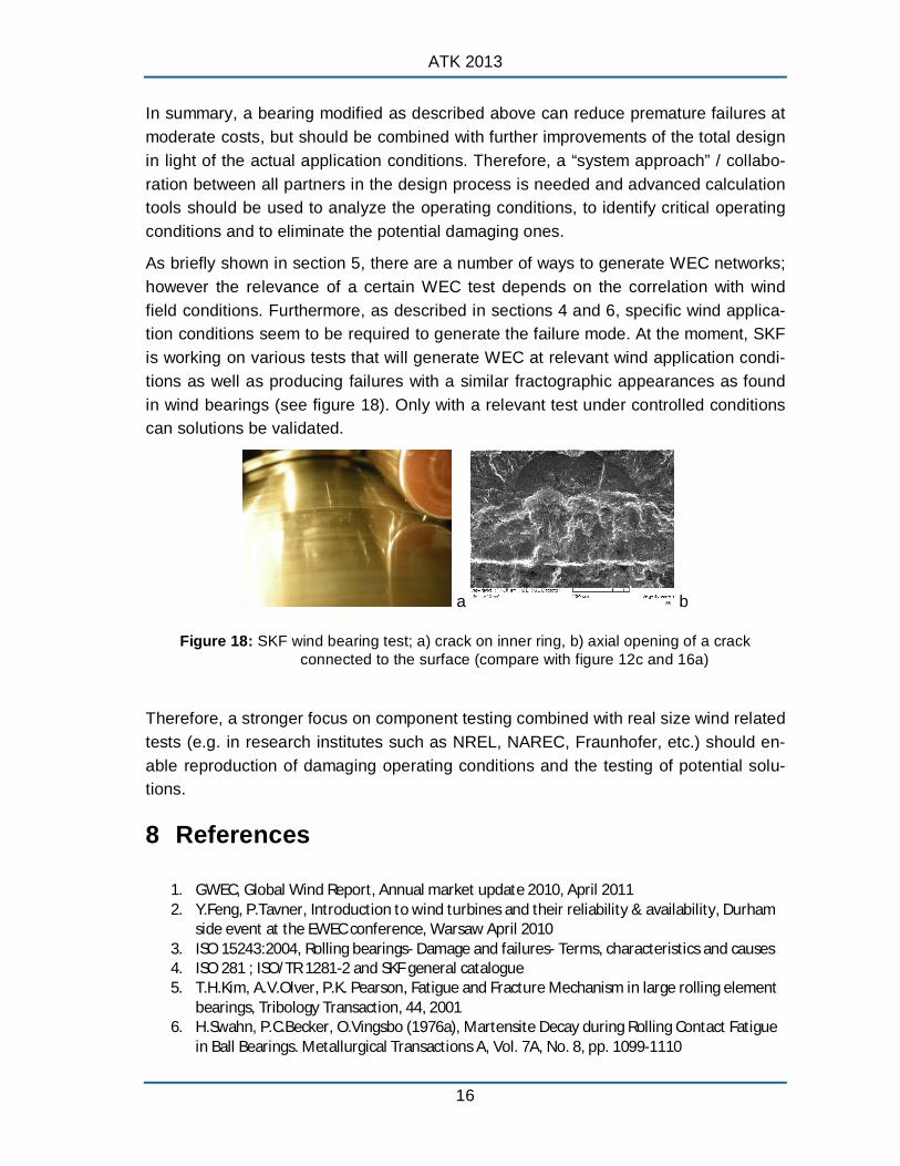
As briefly shown in section 5, there are a number of ways to generate WEC networks; however the relevance of a certain WEC test depends on the correlation with wind field conditions. Furthermore, as described in sections 4 and 6, specific wind application conditions seem to be required to generate the failure mode. At the moment, SKF is working on various tests that will generate WEC at relevant wind application conditions as well as producing failures with a similar fractographic appearances as found in wind bearings (see figure 18). Only with a relevant test under controlled conditions can solutions be validated.
a b
Figure 18: SKF wind bearing test; a) crack on inner ring, b) axial opening of a crack connected to the surface (compare with figure 12c and 16a)
Therefore, a stronger focus on component testing combined with real size wind related tests (e.g. in research institutes such as NREL, NAREC, Fraunhofer, etc.) should enable reproduction of damaging operating conditions and the testing of potential solutions.
8 References
1. GWEC, Global Wind Report, Annual market update 2010, April 2011 2. Y.Feng, P.Tavner, Introduction to wind turbines and their reliability & availability, Durham
side event at the EWEC conference, Warsaw April 2010 3. ISO 15243:2004, Rolling bearings- Damage and failures- Terms, characteristics and causes 4. ISO 281 ; ISO/TR 1281-2 and SKF general catalogue 5. T.H.Kim, A.V.Olver, P.K. Pearson, Fatigue and Fracture Mechanism in large rolling element
bearings, Tribology Transaction, 44, 2001 6. H.Swahn, P.C.Becker, O.Vingsbo (1976a), Martensite Decay during Rolling Contact Fatigue
in Ball Bearings. Metallurgical Transactions A, Vol. 7A, No. 8, pp. 1099-1110
16

Premature Bearing Failures
7. J.Gegner, Tribological Aspects of Rolling Bearing Failures. In: Tribology – Lubricants and Lubrication, Kuo, C.-H. (Ed.), InTech, Rijeka, Croatia, 2011, Chap. 2, pp. 33–94, http://www.intechopen.com/articles/show/title/tribological-aspects-of-rolling-bearingfailures
8. J.Gegner, Frictional Surface Crack Initiation and Corrosion Fatigue Driven Crack Growth, NREL workshop, Broomfield November 2011
9. J.Luyckx, Hammering Wear Impact Fatigue Hypothesis WEC/irWEA failure mode on roller bearings, NREL workshop, Broomfield November 2011
10. W.Holweger, Influence on bearing life by new material phenomena, NREL workshop, Broomfield November 2011
11. M.H.Evans, White structure flaking (WSF) in wind turbine gearbox bearings: effects of ‘butterflies’ and white etching cracks (WECs), Material Science and Technology, Vol. 28 No1, 2012
12. J.P.Molly, Wind Energy – Quo Vadis? DEWI Magazine No 34, February 2009 13. D.Heidenreich, A lean solution to the gearbox life problem in wind turbine drive systems,
Hannover Messe 2011 14. J.Rosinski, D.Smurthwaite, Troubleshooting wind gearbox problems, Gearsolutions 2010 15. A.Heege et.al, Matching experimental and numerical data of dynamic wind turbine loads
by modeling of defects, SAMTECH, EWEC 2009 16. D.Aguglia, R.Rebeschini, Power Transformer Role for Gearbox Mechanical Stress Mitigation
during Voltage Dips Applied to Doubly-Fed Induction Generator based WT, EWEC Warsaw April 2010
17. J.Gegner, W.Nierlich, Mechanical and Tribochemical Mechanisms of Mixed Friction Induced Surface Failures of Rolling Bearings and Modeling of Competing Shear and Tensile Stress Controlled Damage Initiation. Tribologie und Schmierungstechnik, Vol. 58, 2011, No. 1, pp. 10–210
18. W.Nierlich, J.Gegner, Einführung der Normalspannungshypothese für Mischreibung im Wälz-Gleitkontakt. Gleit- und Wälzlagerungen: Gestaltung, Berechnung, Einsatz, VDI-Berichte 2147, VDI Wissensforum, Düsseldorf, Germany, 2011, pp. 277–290 (in German)
19. M.N.Kotzalas, G.L.Doll, Tribological advancements for reliable wind turbine performance, Phil.Trans.R.Soc. A 368, 2010
20. T.Thomas, Schäden durch Schwingungen noch nicht im Griff, VDI Nachrichten, 26.Feb.2010, Nr.8
21. T.Korzeniewski, Gearbox protection concept for wind turbine generator systems, DEWI No.36 2010
22. FVA 541 I, Wälzlagerlebensdauer-Windgetriebe, 2010 23. B.Kamchev, Wind energy encounters turbulence, Lubes'n'greases 2011 24. R.Heemskerk, Challenges on rolling bearings in wind turbines, VDI Gleit- und Wälzlagerun
gen 2011 25. IEC/ISO 61400-1 to 25, Design requirements for wind turbines 26. ANSI/AGMA/AWEA 6006-A03, Standard for design and specification of gearboxes for wind
turbines, 2003 27. O.Klempert, Belastungen im Getriebe werden zum Streitthema, VDI Nachrichten,
14.Mai.2010, Nr.19 28. W.Musial, S.Butterfield, B.McNiff, Improving wind turbine gearbox reliability, NREL, 2007 29. H.Uyama, The mechanism of white structure flaking in rolling bearings, NREL workshop,
Broomfield November 2011 30. N.Kino, K.Otani, The influence of hydrogen on rolling contact fatigue life and its improve
ment, JSAE Rev., 24, 2003
17

ATK 2013
31. K.Tamada, H.Tanaka, Occurrence of brittle flaking on bearings used for automotive electrical instruments and auxiliary devices, Wear, 199, 1996
32. T.Lund, Subsurface initiated rolling contact fatigue – influence of non-metallic inclusions, processing conditions and operating conditions, J.ASTM Int., 7, 2010
33. T.Lund, SABB 1309, ASTM conference, Tampa 2011 34. R.Vegter, J.Slycke, The role of hydrogen on rolling contact fatigue response of rolling ele
ment bearings, J. ASTM Int., 7, 2009 35. I.Strandell, C.Fajers, T.Lund, Corrosion – one root cause for premature failures, 37th Leeds-
Lyon Symposium on Tribology, 2010 36. J.Gegner, W.Nierlich, Sequence of Microstructural Changes during Rolling Contact Fatigue
and the Influence of Hydrogen. Proceedings of the 5th International Conference on Very High Cycle Fatigue, Berger, C. and Christ, H.-J. (Eds.), German Association for Materials Research and Testing (DVM), Berlin, 2011, pp. 557–562
37. J.Gegner, W.Nierlich, Hydrogen accelerated classical rolling contact fatigue and evaluation of the residual stress response, Material Science Forum Vol. 681, 2011
38. J.Lai et.al, The fatigue limit of bearing steels – Part I: A pragmatic approach to predict very high cycle fatigue strength, International J.o.Fatigue, 37, 2012
39. R.Pasaribu, P.Lugt, The composition of reaction layers on rolling bearings lubricated with gear oils and its correlation with rolling bearing performance, Tribology Transaction, STLE, 2012
40. D.Muller, A.Stubenrauch, Einfluß der Ölkomposition auf die Gebrauchsdauer von Wälzlagern, Getlub March 2012
41. I.Nedelcu, E.Piras, A.Rossi, R.Pasaribu, XPS analysis on the influence of water on the evolution of zinc dialkyldithiophosphate-derived reaction layer in lubricated rolling contacts, ECASIA special issue paper, Surf. Interface Anal, 2012
42. B.Han, Bo.X.Zhou, R.Pasaribu, C-ring hydrogen induced stress corrosion cracking (HISCC) tests in lubricating liquid media, European Corrosion Congress, Stockholm, 2011
43. A.Félix-Quinonez, G.E.Morales-Espejel, Film thickness fluctuations in time-varying normal loading of rolling elastohydrodynamically lubricated contacts, Proc. IMechE Vol. 224 Part C, 2010
44. A.Félix-Quinonez, G.E.Morales-Espejel, Film thickness in EHL rolling contacts with transient normal load, ITC Hiroshima 2011
45. W.Holweger, J.Loos, Beeinflußung der Wälzlagerlebensdauer durch neue Werkstoffphänomene in speziellen Anwendungen, Antriebstechnisches Kolloquium Aachen, ATK, 2011
46. M.Brueckner, J.Gegner, A. Grabulov, W. Nierlich, J. Slycke, Butterfly formation mechanisms in rolling contact fatigue, D.Verb.für Materialfor. und -prüf. e.V., 2011
47. J.Lai, J.Wang, E.Ioannides, Fluid-crack interaction in lubricated rolling-sliding contact, Proceedings of the STLE/ASME, IJTC 2008
48. J.Gegner, W.Nierlich, Operational Residual Stress Formation in Vibration-Loaded Rolling Contact. Advances in X-ray Analysis, Vol. 52, 2008, pp. 722-731
49. G.E.Morales-Espejel, V.Brizmer, Micropitting Modelling in Rolling-Sliding Contacts: Application to Rolling Bearings, Trib. Trans. Vol. 54, pp. 625-643, 2011
50. K.Stadler, G.E.Morales-Espejel, V.Brizmer, Micropitting in rolling bearings: influence of lubrication, roughness, wear and ways of prevention, Antriebstechnisches Kolloquium Aachen, ATK 2011
18

Premature Bearing Failures
19