Embed Size (px)
Citation preview

PRELUDE:
Twelve previous evolutions have occurred to the Mountain Mods U2-UFO. Number
13 takes the already modular cube computer case into an overdrive of options. The
new patent pending functions have been named “Hyper Modular”. For nearly 3 years
the right, left, and top panels have been modular, allowing for swapping or rotations of
the panels to give the user a further customized cube. The “Hyper Modular” evolution
now includes these features to the front and back plane of the case. You can rotate
your front panel 180 degrees. The back panel can rotate 90,180, or 270 degrees for
different configurations. You can also mix and match your desired front panel with the
desired back panel. Or purchase different front and/or back panels in the future to
change your cube configuration without needing to purchase an entire case. The
“Hyper Modular” design is truly a revolution in computer case design.
PARTS INCLUDED:
In the image to the left you can see all the parts of the new “Hyper Modular” U2-UFO
cases.
Window panels, front panels, back panels, 5.25 drive bays, and motherboard trays may appear different – depending upon your chosen configuration. For
illustration purposes we are using a Standard U2-UFO front and back panel w/3 UV blue acrylic panels.
You should receive the following (2 boxes packaged in one outer box):
Box 1
____ Front Panel
____ Back Panel
____ Bottom Panel
____ 2 x Struts
____ 3 x Side Panels
____ Acrylic PSU cover plate (2 w/duality back panel)

BASIC ASSEMBLY:
The bottom panel is universal to all Mountain Mods U2-UFO and ASCENSION cases. The bottom side
of the bottom panel has 7 threaded inserts pressed into. The outer 4 inserts are used for attaching the
“Horizon brace” to the floor of the case in Horizontal builds. The 3 inner inserts are used for the
security flange on our motherboard trays. The security flange allows for the motherboard tray to be
stabilized to the floor of the case. The center hole is used for Opti-1203 and Standard U2-UFO builds.
The 2 outer inserts are used for Duality back panel builds. NOTE - These 3 security holes should be
oriented so that they are closer to the front panel. It is possible to install the bottom panel backwards,
which will render the 3 security holes
useless.
Slide the bottom panel into place over the
bottom flange of the back panel. The
corners should appear as they do in the
image to the right. Once into place take
your bag of 16 tapered screws and fasten
the corners of the bottom panel and back
Box 2
____ Motherboard Tray (2 w/duality back panel)
____ 5.25 drive bay(s) (2 w/Opti-1203, Duality and Horizon front panel)
____ Horizon Brace for Horizons only
____ bag of accessories - Include: (Items shown in image to left)
____ caster pack (4 casters)
____ caster nut/bolt pack (16 nuts/16 bolts)
____ motherboard standoff/screw pack (10 standoff/10 3mm)
____ 6 x pci cover plates
____ tapered screw pack (16 - for assembly)
____ thumbscrew pack (50)
____ 6-32 screw pack (10)
____ 2 x power switch/reset switch w/leads
____ 2 x indicator leds/w bezel
____ 2 sets of 120mm FAN HD brackets

panel together with 4 of the tapered screws using a Phillips head screwdriver.
Horizon builds use the same back panel
as the Standard and Opti-1203 U2-UFO.
Simply Rotate the panel 90 degrees and
fasten as above. (Image to the left
shows 90 degree panel rotation.
Tapered screws fit into the tapered screw
holes. They are angled as are the screws
so that the screws do not protrude from
the flange of the case. (Image to the right
shows tapered screws fastened in place)
Use two 6-32 PC screws to tighten the back
panel just left and right of center to the bottom
panel. (image to left illustrates this)
Take your front panel. Orient it how you
choose. The front panel can be installed either
at 0, 90, 180 or 270 degrees. We recommend
only 0 or 180 degree rotations as 90 or 270 will
cause the 5.25 bays to be mounted in a sideways
orientation. Use the same number of tapered
screws and 6-32 screws to fasten the front panel
to the bottom panel. The screw assembly
mirrors what you did on the back panel. When
finished your frame should appear as it does on
the right.
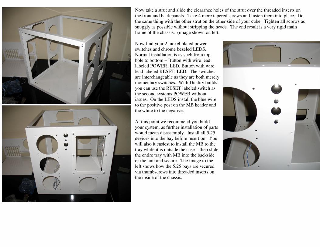
Now take a strut and slide the clearance holes of the strut over the threaded inserts on
the front and back panels. Take 4 more tapered screws and fasten them into place. Do
the same thing with the other strut on the other side of your cube. Tighten all screws as
snuggly as possible without stripping the heads. The end result is a very rigid main
frame of the chassis. (image shown on left.
Now find your 2 nickel plated power
switches and chrome bezeled LEDS.
Normal installation is as such from top
hole to bottom – Button with wire lead
labeled POWER, LED, Button with wire
lead labeled RESET, LED. The switches
are interchangeable as they are both merely
momentary switches. With Duality builds
you can use the RESET labeled switch as
the second systems POWER without
issues. On the LEDS install the blue wire
to the positive post on the MB header and
the white to the negative.
At this point we recommend you build
your system, as further installation of parts
would mean disassembly. Install all 5.25
devices into the bay before insertion. You
will also it easiest to install the MB to the
tray while it is outside the case – then slide
the entire tray with MB into the backside
of the unit and secure. The image to the
left shows how the 5.25 bays are secured
via thumbscrews into threaded inserts on
the inside of the chassis.

The image to the left here indicates the secondary PSU acrylic plate installed via thumbscrews
and the motherboard tray installed and secured via 4 thumbscrews to the back wall of the
chassis.
To the right you can see the trays security
flange fastened to the floor of the case with
it’s respective threaded insert and
thumbscrew. This keeps the tray from
shifting left or right after system
installation. In the corners you can see sets
of 4 holes in the bottom panel. These are
mounting holes for either the included
casters or Mountain Mods acrylic feet. We
recommend installation of feet/casters
prior to installation of system components.
To the right the image shows panels
installed to the sides of the case. Panels
install via 8 thumbscrews into their
respective threaded inserts. Panels can
rotate 90, 180, or 270 degrees and are
interchangeable.
Happy building! And welcome to the new
world of “Hyper Modularity”
Mountain Mods