Embed Size (px)
Citation preview
Building and Environment, Vol. 20, No. 4, pp. 221-231, 1985. 036~1323/85 $3.00 +0.00 Printed in Great Britain. Pergamon Press Ltd.
Preliminary Design Considerations for a Rockbed/Floor Space-heating System
H. SALT*
A solar energy house space-heating system, in which thermal energy is transferred by conduction through a concrete floor from a subfloor rockbed, is considered from the aspect of the store beiag able to maintain comfort conditions with no further solar energy input. The rate of decay of temperature variations alono the floor is also considered. The study uses a solution of the two-dimensional diffusion equation for a composite slab subjected to a sudden chanoe in environment: the pertinent details of the solution are oiven. The study shows that the interaction between the collectors, store and load is more critical in this system than in a conventional active solar space-heating system. It is possible far the floor-heating system to have a storage capability which would give a system performance comparable to that for a conventional system in mild climates, but the system is less suited to mare severe climates. I f a phase-change materialis used in the porous bed, then the bed can be very thin, but a high pressure drop and complex subfloor ductwork would need to be avoided. For thicker beds, it would be advantageous to encourage free convection within them.
N O M E N C L A T U R E
d equivalent spherical diameter of particle in porous medium [m]
Go mass velocity of gas on frontal area basis [kg s -2 m -2] J number of layers in composite slab P pressure [N m- 2]
Re Reynolds number t time Is] x position across composite slab Im]
xj position of interface between jth and (j+ 1)th layers in composite slab [m]
xl thickness of composite slab [m] y position along composite slab [m]
Yl length of composite slab [m].
Greek symbols 7 normalised length of composite slab ~/ normalised position along composite slab /~ viscosity IN s m -2] p density [kg m- s]
normalised position across slab ~kj normalised position of interface between jth and (j + 1)th
layers in composite slab.
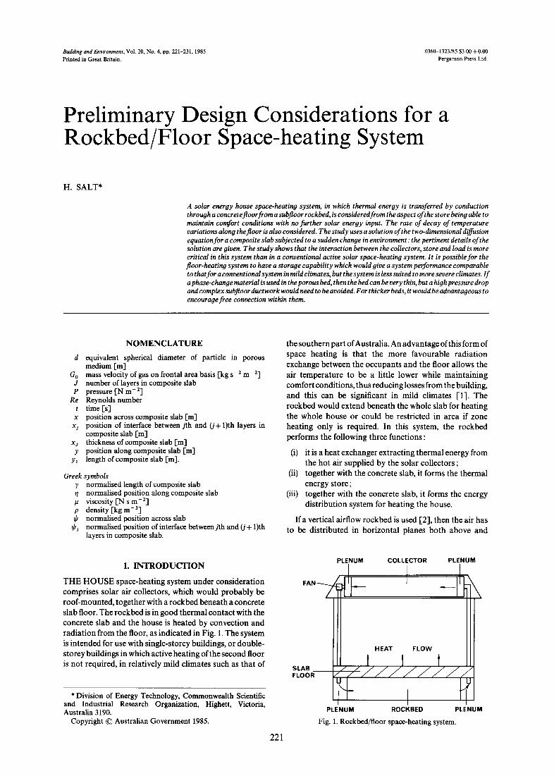
the southern part of Australia. An advantage of this form of space heating is that the more favourable radiation exchange between the occupants and the floor allows the air temperature to be a little lower while maintaining comfort conditions, thus reducing losses from the building, and this can be significant in mild climates [1]. The rockbed would extend beneath the whole slab for heating the whole house or could be restricted in area if zone heating only is required. In this system, the rockbed performs the following three functions :
(i) it is a heat exchanger extracting thermal energy from the hot air supplied by the solar collectors ;
(ii) together with the concrete slab, it forms the thermal energy store;
(iii) together with the concrete slab, it forms the energy distribution system for heating the house.
If a vertical airflow rockbed is used [2], then the air has to be distributed in horizontal planes both above and
1. I N T R O D U C T I O N
THE H O U S E space-heating system under consideration comprises solar air collectors, which would probably be roof-mounted, together with a rockbed beneath a concrete slab floor. The rockbed is in good thermal contact with the concrete slab and the house is heated by convection and radiation from the floor, as indicated in Fig. 1. The system is intended for use with single-storey buildings, or double- storey buildings in which active heating of the second floor is not required, in relatively mild climates such as that of
* Division of Energy Technology, Commonwealth Scientific and Industrial Research Organization, Highett, Victoria, Australia 3190.
Copyright © Australian Government 1985.
221
PLENUM COLLECTOR PLENUM
SLAB FLOOR
HEAT FLOW
t t t
PLENUM ROCKBED PLENUM
Fig. 1. Rockbed/floor space-heating system.

222 H. Salt
below the bed but the system of distribution in the upper plane must not restrict the flow of thermal energy from the rockbed to the slab. Furthermore, the minimum depth of the rockbed will be determined by the need to extract the collected solar energy from the airstream, rather than by its storage function of supplying energy to the house when the collection of solar energy has ceased. The simplicity of the overall system concept should lead to a relatively inexpensive solar space-heating system, but these complications impose restrictions on the design and increase the cost of a vertical airflow rockbed. If the hot air is passed horizontally through the rockbed, the above restrictions do not hold but the following points require consideration :
6) what is the minimum depth of rockbed which will provide adequate storage and maintain the house temperature above an acceptable minimum level for comfort for a minimum period of say 24 h?
(ii) passing hot air through the rockbed horizontally will inevitably cause temperature variations along the floor and it is importnat to know how quickly these will decay when the fan is switched off, since this will influence the design of the rockbed for its operation when the fan is operating ;
(iii) how does hot, buoyant air travel horizontally through a thin, warm rockbed and how does the buoyancy affect the energy exchange between the hot air and the rockbed?
This paper addresses the first two points above and the third point will be covered in a later paper, but firstly, it is instructive to calculate the pressure drop through the rockbed for a number of possible configurations.
2. P R E S S U R E D R O P C A L C U L A T I O N S
Consider a house of 120 m 2 floor area with a solar collector area of 20 m 2 and an airflow of 0.3 m 3 s 1 in the active solar space-heating system. Such a house has been
built at the CSIRO Division of Energy Technology, Melbourne, Australia, and a vertical airflow subfloor rockbed was used for the floor space-heating system [3]. Experience with that house suggests that in mild climates, it is probably only necessary to heat the living area with the active solar system and to rely on diffusion and the occasional use of local heating in the sleeping areas [3]. Accordingly, the floor area being heated by the rockbed could be, say, 10 × 4 m. The rock bed could be di vided into a number of sections and Table 1 shows the airflow, and airflow per unit frontal area of rockbed, for six possible configurations and for three bed depths. For the four different rock sizes, the values of pressure drop have been calculated using the following relation which is valid over the Reynolds number range, 1 < Re < 105 [-4],
2dpP 3500 - 42 + (1)
ylG~ Re
where
Go d Re - (2)
P
The rockbed which is l0 m long and 4 m wide would probably be the easiest and least expensive system to configure but the pressure drop is high for all the bed depths and rock sizes considered. In solar systems, it is desirable to have a low pressure drop across the rockbed in order to keep the power consumption as low as possible. The pressure drop through the collector in the system referred to above was approx. 100 Pa [5] and this value could be taken as a guide when considering the values shown in Table 1, bearing in mind that more subfloor ductwork or increased bed depth will increase the cost of the system. If the collectors mentioned above were used, then the bed which is 4 m long, l0 m wide and 0.15 m deep would only develop a lower pressure drop than that across the collectors if it were filled with 0.05-m rocks ; this bed would probably be the next least expensive to build. If the
Table 1. Pressure drop for a number of rockbed configurations
No. of sections
Airflow per
section (m 3 s- 1)
Length of
section (m)
Width Flow per of Rockbed unit frontal
section height area (m) (m) (m a s I m 2)
Pressure drop (Pa) for equivalent rock diameter (m) of
0.018 0.025 0.038 0.050
1 0.30 10 4 0.15 0.50 0.30 0.25 0.45 0.17
1 0.30 4 10 0.15 0.20 0.30 0.10 0.45 0.07
2 0.15 5 4 0.15 0.25 0.30 0.13 0.45 0.08
2 0.15 2 10 0.15 0.10 0.30 0.05 0.45 0.03
4 0.075 2.5 4 0.15 0.125 0.30 0.0625 0.45 0.0417
4 0.075 1 10 0.15 0.05 0.30 0.025 0.45 0.0167
3998 2780 1772 1327 1121 758 470 348 571 378 229 167 303 202 124 91 95 61 35 25 55 34 19 13
560 379 235 174 182 118 70 51 84 53 30 21 48 30 18 13 17 10 6 4 8 5 3 2
85 55 33 7 29 18 10 4 16 10 5 2 8 5 3 2 3 2 1 1 2 1 1 0.4

Preliminary Design Considerations for a Rockbed/Floor Space-heating System 223
rockbed is divided into two sections, each 5 m long and 4 m wide, then the depth of the bed must be at least 0.3 m and it must be filled with at least 0.038-m rocks for the pressure drop to be lower than that across the collectors. All the remaining bed configurations produce a satisfactory pressure drop across the bed but they require more complex distribution systems or deeper beds.
Since a primary objective of this space-heating system is that it should be simple and relatively inexpensive, it will be important to bear in mind these rockbed pressure drop calculations when considering the results of the influence of bed depth on maintaining comfort conditions in the house. This aspect of the system will now be considered.
3. THEORY
For lightweight houses, which are common in a number of countries, the thermal mass of the house is small relative to that of a floor slab and the rockbed. The surface area of the vertical sides of the slab and the rockbed is very much less than the floor area and if the sides of both are well insulated, then the heat transfer through them can be neglected. The bottom of the rockbed could be insulated but even if it were not, the heat transfer from the rockbed to the ground would necessarily be very small after the system had been operating for some time. Furthermore, for other than very thin rockbeds, which would have small energy storage capacities, the heat transfer rate from the ground to the house would be small because of the thermal resistance of the rockbed.
These observations suggest that a reasonable represen- tation of the temperature decay in this floor space-heating system, after the forced airflow through the rockbed has ceased, would be given by a two-dimensional composite slab which is subjected to a sudden change in the environmental temperature. The composite slab is insulated at the bottom and the sides so that energy is transferred only through the top surface, as shown in Fig. 2, and the slab is infinite in the third dimension. There are two forms of composite slab which are of interest for the space- heating system under discussion :
(i) the two layers of the slab are in perfect thermal contact, i.e. no temperature drop at their interface ;
(ii) a thin layer separates the concrete and the rockbed, which would be the case if the rockbed settled over a
HEAT FLOW ~ x
t t t t t L,J=, xj J-1 ~%-1 xJ-1
i'%-2 x,j-2 I ! I ~q~j Xj
I ( q~j -1 X j - I I I
I ~J 2 I~ q'2 x2 ~J 1 I~ .1 Xl , ' / / , ' / / / / / / , " / / / / / / , " ~ ' . - / / / / / / / / / / / ~ 0 0
q ¥ 0
Y Yl 0
Fig. 2. The two-dimensional multi-layer composite slab.
period of time and left a small air gap beneath the concrete, or if the concrete were poured onto a membrane laid over the rockbed.
The time taken for the temperature in the house to fall to a level chosen as the minimum value allowable for comfort, will give an indication of the performance of the store. A general statement and eigenfunction solution of a multi- layered composite slab has been given in ref. [6] and the meaning of the imaginary eigenvalues which can occur in some layers has been given in ref. [7].
3.1. House temperature The local flux from any point on the floor to the air
immediately above it is determined by their temperature difference and it is easily shown that the mean flux over the whole floor area is determined by the difference between the mean temperature of the floor and that of the air immediately above it. In this study, it is not possible to consider the effects of free convection within the house and we shall assume that the mean house temperature is equal to the mean air temperature immediately above the floor. This is a reasonable approximation because, with floor space-heating systems, the temperature variation from floor to ceiling is very small [3]. It can then be readily shown that for the separable eigenfunction solutions given in ref. [6], only the lowest-order eigenfunction along the slab (in the y-direction in Fig. 2) need be considered. The mean house temperature at any time can then be found by summing the values of only those eigenfunctions across the slab (in the x-direction in Fig. 2) that are associated with the lowest-order eigenfunction along the slab. The lowest- order eigenfunction along the slab is uniform.
4. RESULTS
We shall consider a house of 120 m 2 floor area. For a typical Melbourne brick veneer dwelling, the loss coeffi- cient of the house UA could be taken as 280-300 W K - 1 if the whole house were being heated or 220-250 W K - 1 if only half the house were being heated. These values are for a house of brick veneer construction with 50-mm insulation in the roof and reflective foil in the walls with about 0.6 air changes per h infiltration [8]. Accordingly, we shall consider houses with UA values of 200, 300 and 400 W K - 1 as representing houses with varying degrees of insulation.
The Kunii and Smith model [9] can be used to calculate a value of thermal conductivity of a rockbed. Taking the conductivity of air as 0.026 W m-1 K-1 [10], the conductivity of basalt as 2.2 W m - 1 K - 1 [11], and the emissivity of basalt as 0.9, then the conductivities of beds using 25-, 40- and 50-mm rocks are calculated to be 0.27, 0.36 and 0.41 W m-1 K-1, respectively. The density of basalt can be taken as 2600 kg m-3 [11] and taking the void fraction of the rockbed as 0.46 [12], the density of the bed can be computed as 1400 kg m - 3. The heat capacity of basalt can be assumed to be 880 J kg- 1 K - i [11], and resistance from the floor to the house as 0.11 m 2 K W-1 [13].
Table 2 lists the physical parameters of the first case studied, which was a two-layer composite slab with the concrete being 0.125 m thick and the rockbed 0.15 m deep and using 40-mm rocks.
224 H. Salt
Table 2. House, concrete and rockbed physical parameters
Floor area = 120 m 2 House UA value = 200 W K -1 Loss coefficient per unit floor area = 1.6667 W m- 2 K- 1 Floor to house transfer coefficient = 9.1 W m -2 K - 1 Loss coefficient from floor to ambient = 1.4087 W m- 2 K- 1
Concrete Rockbed Depth (m) 0.125 0.15 Conductivity (W m- 1 K 1) 1.73 0.36 Density (kg m- 3) 2400 1400 Heat capacity (J kg- 1 K 1) 837 880 Diffusivity (m 2 s-1) 8.6121 x I0- 7 2.9254 x 10⁻⁷
We need to consider the uniform eigenfunction along the slab, and to gain some idea of the decay of temperature var iat ions a long the floor, we shall also consider the eigenfunction whose max ima and min ima are separated by 1 m. The latter considera t ion requires tha t the slab is an integral n u m b e r of metres in length.
I f the rockbed settles and leaves a small air gap, then we need to consider the effect on the performance of the system. We shall consider a composi te slab with a 3-mm air layer since one would not expect much settling in a well- laid rockbed. The resistance across a 3-mm air layer in this conduct ion model would be 0.12 m 2 K W -1, which is approximate ly equal to the 0.11 m 2 K W - 1 resistance for a hor izonta l high emit tance surface with heat flow in the upward direct ion [ 13]. The density and heat capacity of air are 1.204 kg m 3 and 1012 J kg-1 K - 1 , respectively [10], giving the diffusivity as 2.1339 x 10 -5 m 2 s - 1
In all the cases considered, only the lowest three t ransverse eigenfunctions were used in determining the temperatures. The sums of these three eigenfunctions matched the initial uniform tempera ture dis t r ibut ions to 1 ~o at the base of the composi te slabs and to 3% at the floor.
4.1. Summary of results for two- and three-layer slabs A n u m b e r of cases have been considered and Tables 3-5
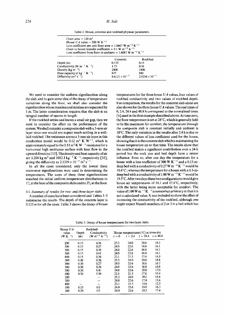
summarise the results. The dep th of the concrete layer is 0.125 m for all the cases. Table 3 shows the decay of house
tempera tures for the three house UA values, four values of rockbed conduct ivi ty and two values of rockbed depth. For comparison, the results for the concrete slab alone are also shown for the three house UA values. The real times of 0, 2.4, 24.4 and 48.8 h cor respond to the normal ised times I-6] used in the first example described above. At t ime zero, the floor t empera ture is set at 28°C, which is generally held to be the m a x i m u m for comfort , the tempera ture th rough the composi te slab is cons tan t initially and ambient is 10°C. The only var ia t ion in the results after 2.4 h is due to the different values of loss coefficient used for the house, showing tha t it is the concrete slab which is main ta in ing the house tempera ture up to tha t time. The results show that the rockbed makes a significant con t r ibu t ion over a 24-h per iod but the rock size and bed dep th have a minor influence. Even so, after one day the tempera ture for a house with a loss coefficient of 300 W K - 1 and a 0.15-m- deep bed with a conductivi ty of 0.27 W m - 1 K - 1 would be 18.6°C ; whereas the tempera ture for a house with a 0.3-m- deep bed with a conduct ivi ty of 1.00 W m - 1 K - 1 would be 19.5°C. After two days these two configurat ions would give house air temperatures of 16.1 and 17.4°C, respectively, with the lat ter being more acceptable for comfort. The value of 1.00 W m - 1 K 1 is somewhat arbi t rary in tha t it is not a calculated value. It was included to show the effect of increasing the conductivi ty of the rockbed, a l though one might expect Nussel t numbers of 2 or 3 in a bed which has
House UA value
(W K -1)
Table 3. Decay of house temperatures for two-layer slabs
Rockbed Depth Conductivity House temperatures (°C) at times (h)
(m) ( W m - I K - 1 ) t = 0 t = 2 . 4 t = 2 4 . 4 t = 4 8 . 8
200 0.15 0.36 25.3 24.0 20.6 18.3 300 0.15 0.27 24.0 22.6 18.6 16.1 300 0.15 0.36 24.0 22.6 18.8 16.1 300 0.15 0.41 24.0 22.6 18.8 16.1 400 0.15 0.36 23.1 21.5 17.4 14.9 200 0.30 0.36 25.3 24.0 20.8 18.8 300 0.30 0.27 24.0 22.6 18.6 16.7 300 0.30 0.36 24.0 22.6 18.8 16.8 300 0.30 0.41 24.0 22.6 19.0 17.0 400 0.30 0.36 23.1 21.5 17.6 15.4 200 25.3 24.0 19.2 15.8 300 24.0 22.6 17.0 13.6 400 -- -- 23.1 21.5 15.6 12.5 300 0.15 1.0 24.0 22.6 19.0 16.3 300 0.30 1.0 24.0 22.6 19.5 17.4
Preliminary Design Considerations for a Rockbed/Floor Space-heating System
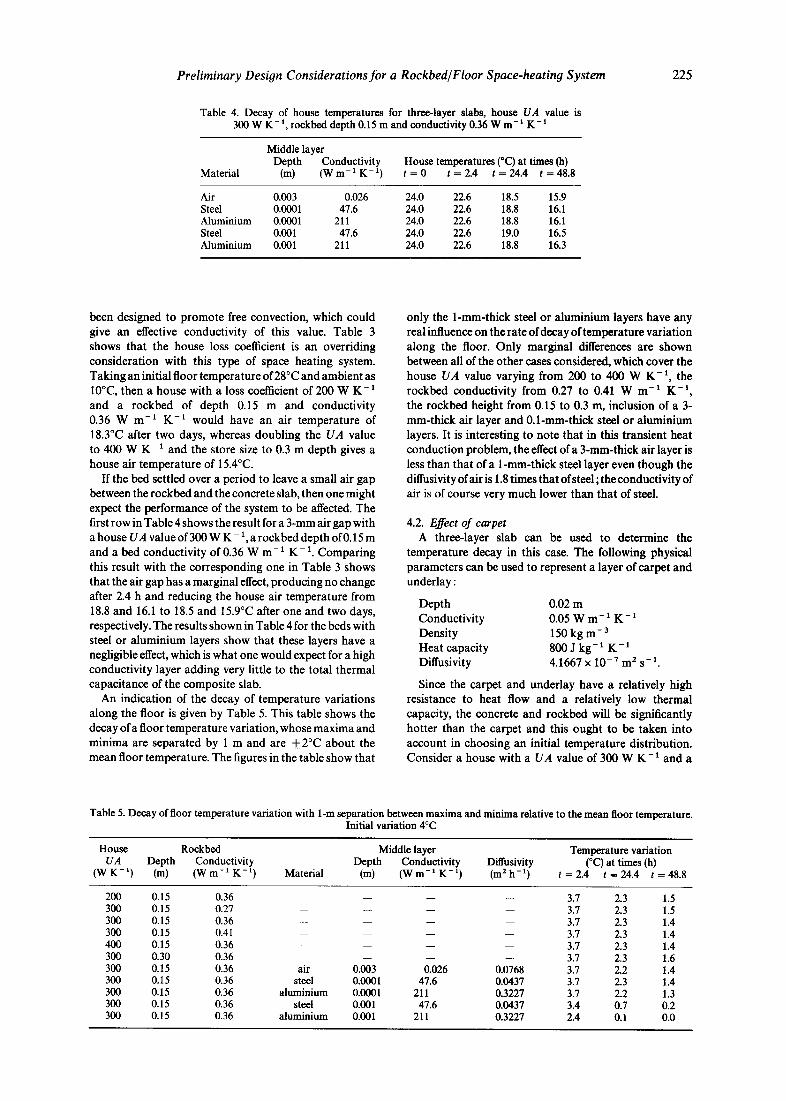
Table 4. Decay of house temperatures for three-layer slabs, house UA value is 300 W K- ~, rockbed depth 0.15 m and conductivity 0.36 W m- 1 K - x
Middle layer Depth Conductivity House temperatures (°C) at times 0a)
Material (m) (W m- ~ K- t) t = 0 t = 2.4 t = 24.4 t = 48.8
Air 0.003 0.026 24.0 22.6 18.5 15.9 Steel 0.0001 47.6 24.0 22.6 18.8 16.1 Aluminium 0.0001 211 24.0 22.6 18.8 16.1 Steel 0.001 47.6 24.0 22.6 19.0 16.5 Aluminium 0.001 211 24.0 22.6 18.8 16.3
225
been designed to promote free convection, which could give an effective conductivity of this value. Table 3 shows that the house loss coefficient is an overriding consideration with this type of space heating system. Taking an initial floor temperature of 28°C and ambient as 10°C, then a house with a loss coefficient of 200 W K - 1
and a rockbed of depth 0.15 m and conductivity 0.36 W m -1 K -1 would have an air temperature of 18.3°C after two days, whereas doubling the UA value to 400 W K - 1 and the store size to 0.3 m depth gives a house air temperature of 15.4°C.
If the bed settled over a period to leave a small air gap between the rockbed and the concrete slab, then one might expect the performance of the system to be affected. The first row in Table 4 shows the result for a 3-mm air gap with a house UA value of 300 W K - 1, a rockbed depth of0.15 m and a bed conductivity of 0.36 W m - 1 K - 1. Comparing this result with the corresponding one in Table 3 shows that the air gap has a marginal effect, producing no change after 2.4 h and reducing the house air temperature from 18.8 and 16.1 to 18.5 and 15.9°C after one and two days, respectively. The results shown in Table 4 for the beds with steel or aluminium layers show that these layers have a negligible effect, which is what one would expect for a high conductivity layer adding very little to the total thermal capacitance of the composite slab.
An indication of the decay of temperature variations along the floor is given by Table 5. This table shows the decay of a floor temperature variation, whose maxima and minima are separated by 1 m and are + 2°C about the mean floor temperature. The figures in the table show that
only the 1-mm-thick steel or aluminium layers have any real influence on the rate of decay of temperature variation along the floor. Only marginal differences are shown between all of the other cases considered, which cover the house UA value varying from 200 to 400 W K - 1 , the rockbed conductivity from 0.27 to 0.41 W m -1 K -1, the rockbed height from 0.15 to 0.3 m, inclusion of a 3- mm-thick air layer and 0.1-mm-thick steel or aluminium layers. It is interesting to note that in this transient heat conduction problem, the effect of a 3-mm-thick air layer is less than that of a 1-mm-thick steel layer even though the diffusivity of air is 1.8 times that of steel; the conductivity of air is of course very much lower than that of steel.
4.2. Effect of carpet A three-layer slab can be used to determine the
temperature decay in this case. The following physical parameters can be used to represent a layer of carpet and underlay:
Depth 0.02 m Conductivity 0.05 W m - 1 K - 1 Density 150 kg m - 3 Heat capacity 800 J k g - 1 K - 1
Diffusivity 4.1667 x 10⁻⁷ m 2 s-1.
Since the carpet and underlay have a relatively high resistance to heat flow and a relatively low thermal capacity, the concrete and rockbed will be significantly hotter than the carpet and this ought to be taken into account in choosing an initial temperature distribution. Consider a house with a UA value of 300 W K - 1 and a
Table 5. Decay of floor temperature variation with 1-m separation between maxima and minima relative to the mean floor temperature. Initial variation 4°C
House Rockbed Middle layer Temperature variation UA Depth Conductivity Depth Conductivity Ditfusivity (°C) at times (h)
(W K - ~) (m) (W m- ~ K- 1) Material (m) (W m- ~ K- ~) (m 2 h - 1) t = 2.4 t = 24.4 t = 48.8
200 0.15 0 . 3 6 . . . . 3.7 2.3 1.5 300 0.15 0.27 . . . . 3.7 2.3 1.5 300 0.15 0.36 . . . . 3.7 2.3 1.4 300 0.15 0 . 4 1 . . . . 3.7 2.3 1.4 400 0.15 0.36 . . . . 3.7 2.3 1.4 300 0.30 0.36 . . . . 3.7 2.3 1.6 300 0.15 0.36 air 0.003 0.026 0.0768 3.7 2.2 1.4 300 0.15 0.36 steel 0.0001 47.6 0.0437 3.7 2.3 1.4 300 0.15 0.36 aluminium 0.0001 211 0.3227 3.7 2.2 1.3 300 0.15 0.36 steel 0.001 47.6 0.0437 3.4 0.7 0.2 300 0.15 0.36 aluminium 0.001 211 0.3227 2.4 0.1 0.0

226 H. Salt
Table 6. Decay of house temperatures with carpet; house UA value is 300 W K
Depth (m)
0.15 0.15 0.30 0.30
Rockbed Conductivity House temperatures (°C) at times (hl ( W m - l K -1) t = 0 t-=2.4 t=24.4 t:-~48.8
0.41 18.0 17.6 16.1 14.9 1.00 18.0 17.6 16.1 15.0 0.41 18.0 17.6 16.1 15.3 1.00 18.0 17.6 16.3 15.5
floor area of 120 m 2, and let the house temperature and ambient be 18 and 10°C, respectively, then the heat loss from the house per unit area of floor will be 20 W m - 2. If this heat flow is being supplied from the concrete and rockbed, and taking the heat transfer coefficient from the surface of the carpet as 9.1 W m- 2 K, then the temperature of the surface of the carpet will be 20.2°C and the temperature at the interface between the concrete and the underlay will be 28.2°C. We shall assume there is a uniform temperature across the concrete and rockbed initially. Table 6 shows the decay of the house temperature for a house with a UA value of 300 W K - ~ when the floor is covered with 20 mm of carpet and underlay. Results are given for two depths of rockbed and for two rockbed conductivities.
The house temperatures in Table 6 are significantly lower than those given in Tables 3 and 4. The reason for this is that the slab and rockbed had the same nominal initial temperature in all cases and hence the initial temperature of the surface of the carpet is significantly lower. The figures in Table 6 cannot be compared directly with those in Tables 3 and 4. A meaningful comparison is made in Section 5.
Table 7 shows the decay of temperature variations along the surface of the carpet, whose maxima and minima are separated by 1 m and are +2°C about the mean temperature of the surface of the carpet. Comparing the figures in Table 7 with those in Table 5 shows that the carpet has a negligible effect on the decay of temperature variations along the floor.
4.3. i~hase-change material A porous bed of encapsulated phase-change material
(PCM) could be used rather than rock and because of the very high thermal capacity, such a bed could be very shallow. In an actual installation, it may be necessary to encapsulate the PCM in cylinders and to place these inside larger cylinders beneath the concrete so that the PCM could be replaced if it degraded over a period of time. However, for the purpose of these preliminary calcu-
Table 7. Decay of floor temperature variation with carpet
Rockbed Temperature variation (°C) Depth Conductivity at times (h)
(m) (W m - 1 K - 1) t = 2.4 t = 24.4 t = 48.8
0.15 0.41 3.7 2.2 1.3 0.30 0.41 3.7 2.3 1.5
lations, the PCM layer can be considered simply as a porous bed. The characteristics of calcium chloride hexahydrate have been used for the properties of the PCM for the purpose of calculation. The temperature of fusion of calcium chloride hexahydrate can be reduced [14, 15] if necessary so that the temperature of the floor would not exceed 28°C. The properties of CaCI/. 6H20 are [16]
Solid and liquid heat capacity 2000 J kg- 1 K 1
Solid and liquid density 1500 kg m-3 Latent heat of fusion 170 000 J kg ~ 1 Temperature of fusion 30°C
The thermal conductivity of CaC1 z • 6H20 is 0.56 and 0.64 W m- 1 K - 1 in its liquid and solid states, respectively, at 30°C [17], so that a value of 0.6 W m - 1 K - ~ would be suitable for these calculations if the PCM is considered as a single-layer bed. Taking the void fraction to be the same as that for the rockbeds, namely 0.46, then the density of the PCM bed is calculated to be 810 kg m 3. If the PCM in the bed experiences a temperature swing of 10°C about its fusion temperature, then the storage of both sensible and latent heat can be expressed as an equivalent heat capacity for the PCM of 19 000 J kg- 1 K 1. Three PCM beds have been considered, being 0.05, 0.025 and 0.0125 m deep. Table 8 shows the decay of house temperatures for the three different house UA values and the three bed depths.
The decay of the temperature variation along the floor with 1-m separation between maxima and minima which are + 2°C about the mean floor temperature is given in Table 9 for the three bed depths. As in the previous cases shown in Table 5, the effect due to changing the house UA value is only marginal.
The thermal capacities of the 0.0125- and 0.025-m-deep PCM beds are 192 and 385 kJ K-~ m -2, respectively, which are comparable to the values of 185 and 370 kJ K 1 m-2 for the 0.15- and 0.3-m-deep rockbeds. Accordingly, comparing Table 8 with Table 3 shows the value of having all the thermal mass of the porous layer located immediately beneath the concrete. After one and two days, the improvement is between 1 and 3~o for the lower capacity beds and between 2 and 8~ for the higher capacity beds, depending on the effective conductivity of the rockbeds. However, Tables 4 and 9 show that temperature variations along the floor are more persistent with the PCM beds and the bed depth has a greater influence. For a house with a UA value of 300 W K-1, increasing the rockbed depth from 0.15 to 0.3 m does not increase the temperature variation from 2.3°C at 24.4 h for a bed whose conductivity is 0.36 W m- l K - ~, whereas increasing the depth of the PCM bed from 0.0125 to 0.025 m increases the temperature variation from 2.6 to 2.9°C.
Preliminary Design Considerations for a Rockbed/Floor Space-heating System 227
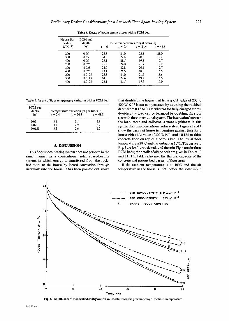
Table 8. Decay of house temperatures with a PCM bed
House UA PCM bed value depth
(W K - t) (m) House temperatures (°C) at times (h)
t = 0 t = 2.4 t = 24.4 t = 48.8
200 0.05 25.3 24.0 22.4 21.0 300 0.05 24.0 22.8 20.6 19.2 400 0.05 23.1 21.5 19.4 17.7 200 0.025 25.3 24.0 21.9 19.9 300 0.025 24.0 22.8 20.1 17.7 400 0.025 23.1 21.5 18.6 16.5 200 0.0125 25.3 24.0 21.2 18.6 300 0.0125 24.0 22.6 19.2 16.5 400 0.0125 23.1 21.5 17.7 15.0
Table 9. Decay of floor temperature variation with a PCM bed
PCM bed depth Temperature variation (°C) at times (h)
(m) t = 2.4 t = 24.4 t = 48.8
0.05 3.8 3.1 2.6 0.025 3.8 2.9 2.2 0.0125 3.8 2.6 1.7
5. D I S C U S S I O N
This floor space-heat ing system does not perform in the same m a n n e r as a convent ional solar space-heat ing system, in which energy is t ransferred from the rock- bed store to the house by forced convect ion th rough ductwork into the house. It has been pointed out above
tha t doubl ing the house load from a UA value of 200 to 400 W K - 1 is no t compensa ted by doubl ing the rockbed depth from 0.15 to 0.3 m whereas for fully-charged stores, doubl ing the load can be ba lanced by doubl ing the store size with the convent ional system. The interact ion between the load, store and collector is more significant in this system than in a convent ional solar system. Figures 3 and 4 show the decay of house tempera ture against t ime for a house with a UA value of 300 W K - 1 and a 0.125-m-thick concrete floor on top of a porous bed. The initial floor t empera ture is 28°C and the ambien t is 10°C. The curves in Fig. 3 are for four rock beds and those in Fig. 4 are for three P C M beds ; the details of all the beds are given in Tables 10 and 11. The tables also give the thermal capacity of the concrete and porous bed per m 2 of floor area.
If the ambien t tempera ture is at 10°C and the air tempera ture in the house is 18°C before the solar input,
|
o
~kE 20:4-C
24
~ ~ , ~ BED CONDUCTIVITY 0.41W.m-l.K -1
BED CONDUCTIVITY 1"0 W.m-l.K -1
C CARPET FLOOR COVERING
2O ~
18 ~ E
0'3
18 ~ 0.15 I I I i b
10 20 30 40 50 TIME, HRS
Fig. 3. The influence of the rockbed configuration and the floor covering on the decay of the house temperature.

228 H. Salt
P
tv
13. :E ~J I.-
o
24
22
20
18
16[-- I
0 10 I I
20 30
T I M E , H R S
Fig. 4. Decay of house temperature for PCM beds.
0'05
0-025
0'0125
] I 40 50
then the temperature of the floor would be 20.2°C. If we postulate a collector output of 6 MJ m - 2 for a particular day, which would be a reasonable estimate for a good day during winter in Melbourne, and a collector area of 20 m 2 then the energy input to the store would be 120 MJ. Table 10 shows the mean floor temperature 7'(1) to which an un- carpeted floor would rise if the whole floor area of 120 m 2 were heated, and if only 40 m E of the floor were heated, and the store is heated uniformly with no loss to the house or elsewhere. While this would not be true in practice, it is not an unreasonable approximation for a well-insulated store beneath a house which makes full use of passive solar heating. The time taken for the house air temperature to fall to 18°C is shown as the 'Dura t ion ' in Table 10. A heated floor area of 40 m 2 has been considered for the reasons given in Section 2 and in that case the floor temperature and duration would apply to the living area with the rest of
the house being somewhat cooler. However, the reduction in the UA value for part-house heating has been ignored for these illustrative examples so that the results shown for the duration are pessimistic when only 40 m 2 of the floor is being heated.
For a house with a carpeted floor, the surface of the carpet would be 20.2°C and, as discussed above, the temperature at the interface between the concrete and the underlay would be 28.2°C. Since the carpet has a very small thermal capacity but a high thermal resistance, it can be assumed that all the energy delivered by the solar collectors is stored uniformly in the rockbed and concrete. The fifth column in Table 11 shows the temperatures to which the different stores would be raised. The temperatures shown in column 6 of Table 11 for the surface of the carpet are consistent with the normalised temperatures which were used to derive the results shown
Table 10. Examples of maintaining temperature in an uncarpeted house with 20 m 2 collector
Bed material
Bed Bed Thermal depth conductivity capacity
(m) ( W m - I K -1) ( J K - l m -2)
Floor area = 120 m 2 Floor area = 40 m 2 T(I) Duration 7"(1) Duration (°C) (h) (°C) (h)
Rock 0.15 0.41 435,900 Rock 0.30 0.41 620,700 Rock 0.15 1.0 435,900 Rock 0.30 1.0 620,700 PCM 0.0125 0.6 443,475 PCM 0.025 0.6 635,850 PCM 0.05 0.6 1,020,600
22.5 7.2 27.1 27.0 21.8 3.9 25.0 19.7 22.5 7.8 27.1 28.3 21.8 4.2 25.0 23.8 22.5 8.6 27.0 30.2 21.8 4.5 24.9 27.4 21.2 1.6 23.1 19.4

Preliminary Design Considerations for a Rockbed/Floor Space-heating System
Table 11. Examples of maintaining temperature in a carpeted house with 20 m 2 collector
229
Bed Bed Store Floor Initial store Initial carpet depth conductivity capacity area temperature temperature Duration (m) (W m - 1 K - t) (J K - 1 m - 2) (m 2) (°C) (°C) (h)
0.15 0.41 435,900 120 30.5 21.5 6.7 0.15 0.41 435,900 40 35.1 24.1 29.6 0.15 1.00 435,900 120 30.5 21.5 7.4 0.15 1.00 435,900 40 35.1 24.1 30.5 0.30 0.41 620,700 120 29.8 21.1 4.1 0.30 0.41 620,700 40 33.0 22.9 20.3 0.30 1.00 620,700 120 29.8 21.1 4.5 0.30 1.00 620,700 40 33.0 22.9 24.0
in Table 6. The 'Duration' is the time taken for the house temperature to fall to 18°C. Comparing the times given for the 'Duration' in Tables 10 and 11 shows that the carpet has a negligible effect on the overall performance. Comparing the initial floor temperatures 7"(1) in Table 10 with the initial carpet temperature in Table 11 shows that there is less temperature variation in the house when the floor is covered with carpet. However, the temperature of the concrete and rockbed would be increased by approx. 8 K with the carpeted floor and that would decrease the efficiency of the solar collectors. The reduction is small for well-designed collectors operating with inlet temperatures in the range 20-30°C.
Assuming no system losses, an input of 120 MJ to the store of a conventional solar space-heating system would allow the house to be maintained at a temperature of 19°C for 12.4 h with ambient at 10°C and a house UA value of 300 W K - 1. It is interesting to note that in a conventional solar system the store would typically be 0.25 m a of rockbed per m 2 of collector area, that is, 350 kJ m -2 K - 1 [10]. This would correspond to heating a floor area of approx. 16 m 2 with the 0.15-m-deep rockbed and it is clear
from Table 10 that the floor would become too hot if only this area were heated in the system being studied. The house air temperature of 19°C for a conventional system has been reduced to 18°C for the floor heating system to allow for the more favourable radiation exchange in the latter system. The duration values shown in Table 10 illustrate the interactive nature of the house, store and collector. If the whole floor is heated, the 0.0125-m PCM bed will maintain the house temperature at 18°C or above for more than five times as long as the 0.05-m PCM bed. For the part-floor heating case, the factor is 1.6. Hence the ratio of store size to collector area is critically important in this system, as is the ratio of collector area to the load. The results for the rockbed cases show the benefit of designing the bed to have a high thermal conductivity, which might be achieved in effect by encouraging free convection within the bed. Since the thermal mass of the 0.0125- and 0.025-m- deep PCM beds is approximately the same as that for the 0.15- and 0.3-m-deep rockbeds, the results for the PCM beds show what could be achieved with the rockbeds if they had very high effective thermal conductivities.
Figures 5 and 6 illustrate the interaction between the
24 40m 2 HEATED FLOOR AREA
120m 2 HEATED FLOOR AREA
23 C CARPET FLOOR COVERING
C
_ i ~ l ' i , , . I
10 20 30 40
TIME, HRS
Fig. 5. Decay of house temperature for a 0.15-m-deep rockbed, with and without carpet floor covering and 40 m 2 or 120 m 2 of heated floor area.
22
°~ 21
<~ 2o ..=,
18
230 H. Salt
24
23
22
o U 21
,~ 20 ,.=,
18
17
40rn 2 HEATED FLOOR AREA
120m 2 HEATED FLOOR AREA
CARPET FLOOR COVERING
~ ~..~ ~ ~ . ~ c
10 20 30 40
T IME, HRS
Fig. 6. Decay of house temperature for a 0.3-m-deep rockbed, with and without carpet floor covering and 40 m 2 or 120 m 2 of heated floor area.
i
5O
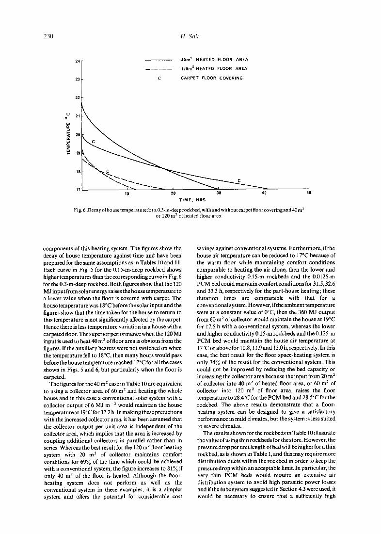
components of this heating system. The figures show the decay of house temperature against time and have been prepared for the same assumptions as in Tables 10 and 11. Each curve in Fig. 5 for the 0.15-m-deep rockbed shows higher temperatures than the corresponding curve in Fig. 6 for the 0.3-m-deep rockbed. Both figures show that the 120 MJ input from solar energy raises the house temperature to a lower value when the floor is covered with carpet. The house temperature was 18°C before the solar input and the figures show that the time taken for the house to return to this temperature is not significantly affected by the carpet. Hence there is less temperature variation in a house with a carpeted floor. The superior performance when the 120 MJ input is used to heat 40 m 2 of floor area is obvious from the figures. If the auxiliary heaters were not switched on when the temperature fell to 18°C, then many hours would pass before the house temperature reached 17°C for all the cases shown in Figs. 5 and 6, but particularly when the floor is carpeted.
The figures for the 40 m 2 case in Table 10 are equivalent to using a collector area of 60 m 2 and heating the whole house and in this case a conventional solar system with a collector output of 6 MJ m - 2 would maintain the house temperature at 19°C for 37.2 h. In making these predictions with the increased collector area, it has been assumed that the collector output per unit area is independent of the collector area, which implies that the area is increased by coupling additional collectors in parallel rather than in series. Whereas the best result for the 120 m 2 floor heating system with 20 m 2 of collector maintains comfort conditions for 69% of the time which could be achieved with a conventional system, the figure increases to 81 ~o if only 40 m 2 of the floor is heated. Although the floor- heating system does not perform as well as the conventional system in these examples, it is a simpler system and offers the potential for considerable cost
savings against conventional systems. Furthermore, if the house air temperature can be reduced to 17°C because of the warm floor while maintaining comfort conditions comparable to heating the air alone, then the lower and higher conductivity 0.15-m rockbeds and the 0.0125-m PCM bed could maintain comfort conditions for 31.5, 32.6 and 33.3 h, respectively for the part-house heating; these duration times are comparable with that for a conventional system. However, if the ambient temperature were at a constant value of 0°C, then the 360 MJ output from 60 m 2 of collector would maintain the house at 19°C for 17.5 h with a conventional system, whereas the lower and higher conductivity 0.15-m rockbeds and the 0.125-m PCM bed would maintain the house air temperature at 17°C or above for 10.8, 11.9 and 13.0 h, respectively. In this case, the best result for the floor space-heating system is only 74~o of the result for the conventional system. This could not be improved by reducing the bed capacity or increasing the collector area because the input from 20 m 2 of collector into 40 m 2 of heated floor area, or 60 m 2 of collector into 120 m 2 of floor area, raises the floor temperature to 28.4°C for the PCM bed and 28.5°C for the rockbed. The above results demonstrate that a floor- heating system can be designed to give a satisfactory performance in mild climates, but the system is less suited to severe climates.
The results shown for the rockbeds in Table 10 illustrate the value of using thin rockbeds for the store. However, the pressure drop per unit length of bed will be higher for a thin rockbed, as is shown in Table I, and this may require more distribution ducts within the rockbed in order to keep the pressure drop within an acceptable limit. In particular, the very thin PCM beds would require an extensive air distribution system to avoid high parasitic power losses and if the tube system suggested in Section 4.3 were used, it would be necessary to ensure that a sufficiently high

Prel iminary Design Considerat ions f o r a Rockbed /F loor Space-heat ing Sys tem 231
transfer coefficient could be achieved between the airstream and the PCM. If a deeper rockbed could be designed to encourage free convection within it, it may offer a less expensive alternative to using more ductwork in a thinner rockbed. The performance of the deep rockbed could be comparable with that of the thin beds if strong free convective flo~¢ could be developed within it.
6. C O N C L U S I O N S
Parameters which affect the performance of a rockbed/floor space-heating system have been in- vestigated from the aspect of the ability of the system to maintain comfort conditions with no further solar input. It has been shown that relatively thin rockbeds beneath a concrete slab floor are able to maintain comfortable conditions in a house for in excess of one day in mild climates, but the performance of the system is more limited in more severe climates. However, a 0.125-m-thick concrete slab floor alone would not be satisfactory except for very well insulated houses in mild climates.
It has been shown that placing carpet on the floor has no significant direct effect on the overall performance of the system except to reduce temperature variations. However, since the store is operated at a higher temperature with the carpeted floor, the efficiency of the solar collectors will be reduced. The extent of the reduction will depend on the design of the collectors.
The sizing of the solar components is more criticalin this system than in a conventional active solar space-heating system since the performance can be markedly degraded by oversizing the store or the collector; the latter being due
to the floor becoming too hot and the fan having to be turned off. It may be necessary to minimise temperature variations along the bed when charging since this work has shown that they are persistent when the store is discharging.
Phase-change materials offer the possibility of making a very thin subfloor thermal store but care would be required in the design to avoid problems with excessive pressure drop while maintaining an adequate heat transfer coefficient with the airstream when the material is being charged.
This preliminary study has shown the range of the porous bed parameters which will be pertinent to a computer simulation of the system using climatic data, hence the cost of the optimisation of the system can be kept to a minimum. If the simulation is performed on a house of lightweight construction which has negligible thermal mass, then after the fan has been switched offat the end of one day, the method described in this paper could be used to predict the house and store temperatures before the fan is switched on again on the following day.
A more detailed account of the technique used to derive the results reported in this paper is available from the author at the CSIRO Division of Energy Technology, P.O. Box 26, Highett, Victoria, Australia 3190. The actual equations used for the two- and three-layer composite slabs are given and these would allow any such composite slabs to be studied, in addition to the particular ones being reported here.
Acknowledgements--The author would like to acknowledge the support given by the Victorian Solar Energy Council for this work.
REFERENCES
1. R.V. Dunkle, Design considerations and performance for an integrated solar air heater and gravel bed thermal store in a dwelling. ISES-ANZ Section Symposium on Applications of Solar Energy Research and Development in Australia, Melbourne (1975).
2. H. Salt, M. K. Peck, D. Proctor and D. J. Close, A house underfloor heating system using solar energy. ISES-ANZ Section Symposium on (1) Solar Energy Collection at Temperatures above 100°C (2) Solar Air-conditioning Systems, Melbourne (1978).
3. M.J. Wooldridge and L W. Welch, A summary of the major results from the first winter of operation of the CSI RO low energy consumption house at Highett, Victoria. Aust. Refrig., Air Condit. Heat. 34(12), 23 (1980).
4. R.V. Dunkle and W. M. J. Ellul, Randomly-packed particulate bed regenerators and evaporative coolers, Mech. chem. Engng Trans. Inst. Engrs Aust. MC8(2), 117 (1972).
5. M.K. Peck and D. Proctor, Design and performance of a roof integrated solar air heater, Sol. Energy 31(2), 183 (1983).
6. H. Salt, Transient conduction in a two-dimensional composite slab--I. Theoretical development of temperature modes, Int. J. Heat Mass Transfer 8(11), 1611 (1983).
7. H. Salt, Transient conduction in a two-dimensional composite slab II. Physical interpretation of temperature modes, Int. J. Heat Mass Transfer 8(11), 1617 (1983).
8. M.J. Wooldridge, CSIRO Division of Energy Technology, Personal communication (1984). 9. D. Kunii and J. M. Smith, Heat transfer characteristics of porous rocks, A.I.Ch.E. Jl 6, 71 (1960).
10. J.A. Duffle and W. A. Beckman, Solar Energy Thermal Processes. John Wiley, New York (1980). 11. Smithsonian Physical Tables, 9th Revised Edition, prepared by William Elmer Forsythe. The
Smithsonian Institution Press, Washington, DC (1969). 12. D.J. Close, Rock pile thermal storage for comfort air conditioning. Mech. chem. Trans. Inst. Engrs Aust.
MCI(1), 11 (1965). 13. CSIRO Division of Building Research, Heat Transfer Data for Building Components and Elements. 14. A. Jaffrin and P. Cadier, Latent heat storage applied to horticulture. La Baronne solar greenhouse, Sol.
Energy 28(4), 313 (1982). 15. B.K. Huang, M. Toksoy and Y. A. Cengel, Transient response of latent heat storage in greenhouse solar
system. Presented at the 1983 Summer Meeting American Society of Agricultural Engineers, Montana State University, Bozeman, Montana (June 1983).
16. P.-H. Theumissen and J.-M. Buchlin, Numerical optimization of a solar air heating system based on encapsulated PCM storage, Sol. Energy 31(3), 271 (1983).
17. A.G. Turnbull, CSIRO Division of Mineral Chemistry, Personal communication (1984).


![HEATING CIRCUIT CONTROLLER WITH SOLID FUEL BOILER2].pdf · HEATING CIRCUIT CONTROLLER WITH SOLID FUEL BOILER ... PRELIMINARY START-UP– enables blocking the boiler return temp](https://img.dokumen.tips/doc/110x75/5b5bf7397f8b9a2d458eb2be/heating-circuit-controller-with-solid-fuel-2pdf-heating-circuit-controller.jpg)


