Embed Size (px)
Citation preview

Precision Validation of Radar System Performance in the Field
Tom Hoppin
Application Specialist
Component Test Division
Keysight Technologies
August 19, 2015
© Keysight
Technologies 2015 1
Page
Precision Validation of Radar System
Performance in the Field
2
© Keysight
Technologies 2015
Page
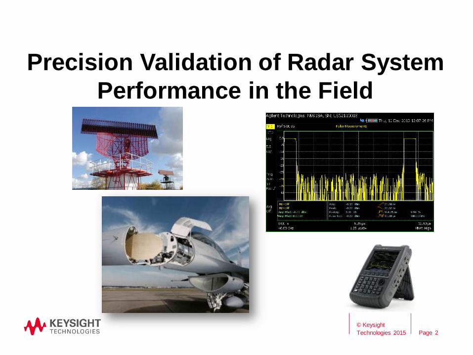
Outline
• Radar and Monopulse Systems
• Time and Frequency Domain Measurements
• Field Test Requirements
• Measurement Examples
• Remote Operation
• Cost of Test
• Conclusions
3
© Keysight Technologies 2015
Page
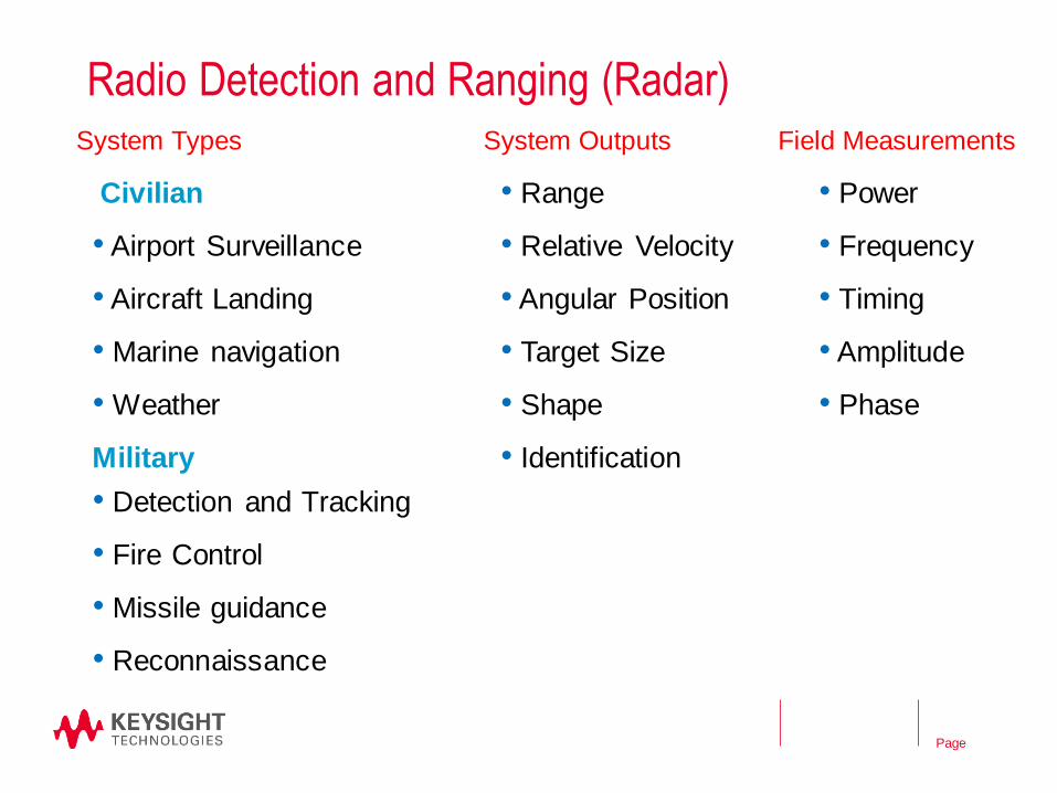
Radio Detection and Ranging (Radar)
Civilian
• Airport Surveillance
• Aircraft Landing
• Marine navigation
• Weather
Military
• Detection and Tracking
• Fire Control
• Missile guidance
• Reconnaissance
4
System Types
• Range
• Relative Velocity
• Angular Position
• Target Size
• Shape
• Identification
System Outputs
• Power
• Frequency
• Timing
• Amplitude
• Phase
Field Measurements
© Keysight Technologies 2015
Page
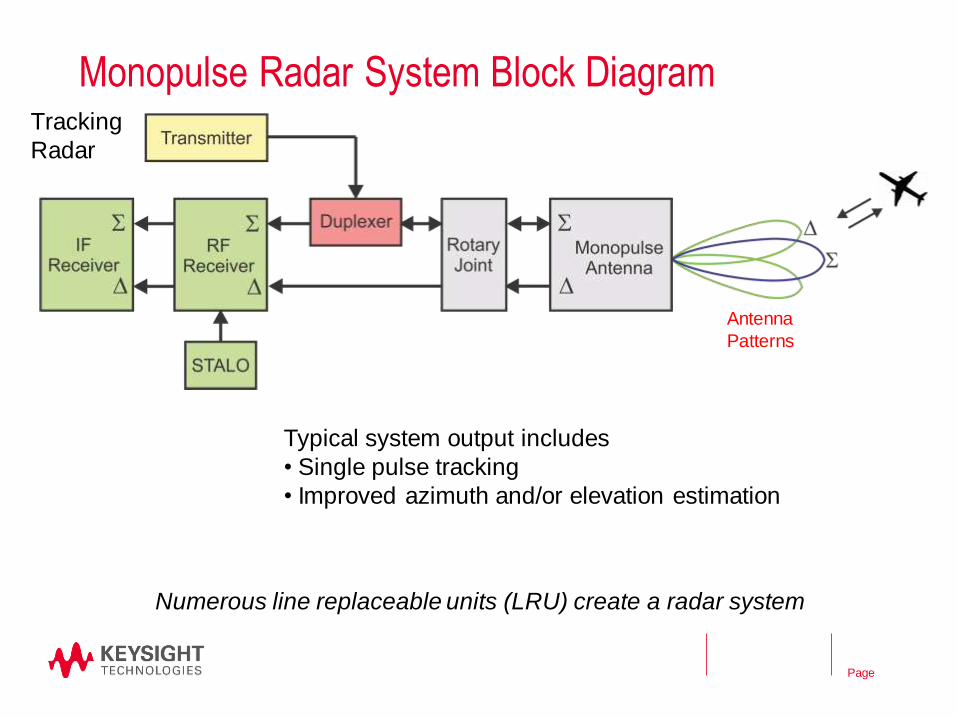
Monopulse Radar System Block Diagram
5
Typical system output includes
• Single pulse tracking
• Improved azimuth and/or elevation estimation
Antenna
Patterns
Tracking
Radar
Numerous line replaceable units (LRU) create a radar system
© Keysight Technologies 2015
Page
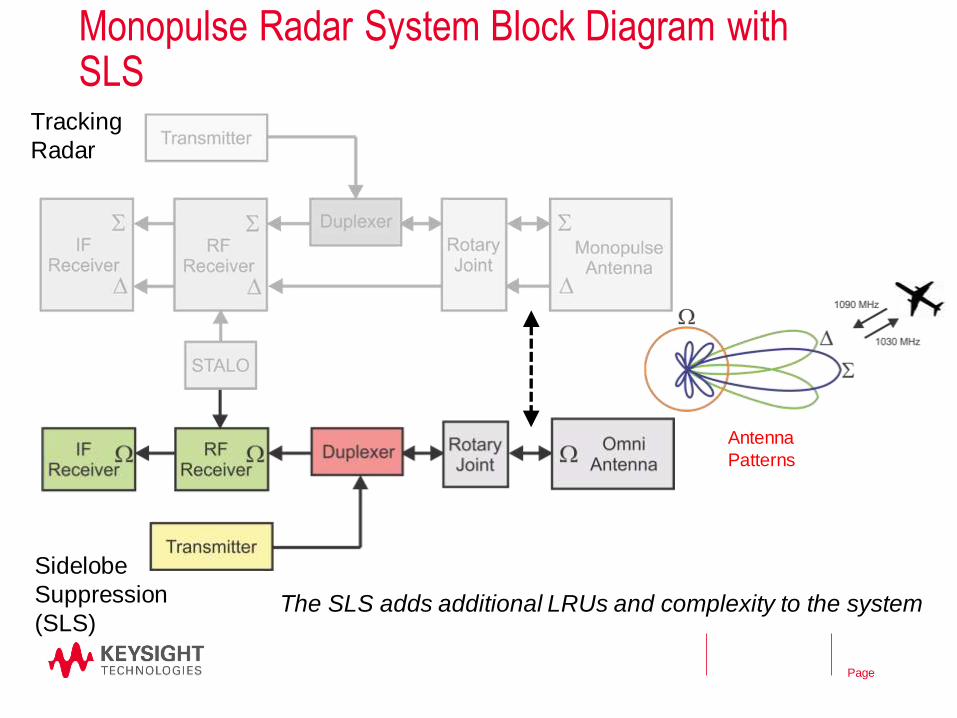
Monopulse Radar System Block Diagram with SLS
6
Sidelobe
Suppression
(SLS)
Tracking
Radar
Antenna
Patterns
The SLS adds additional LRUs and complexity to the system
© Keysight Technologies 2015

Page
Example: Air Traffic Control Radar Beacon System (ATCRBS)
P1 P3
P2
P1 P3
P2
P1 P3
P2
#1
#2
#1
#2
P1>P2
P2>P1
Antenna
Patterns
S
W
Numerous instrument types are required for testing at the LRU level
7
Transponder
receives
7
© Keysight Technologies 2015

Page
Time and Frequency Domains
8
Time Frequency
Time Frequency
Absolute
Relative
Example: Pulsed Radar
© Keysight Technologies 2015
Page
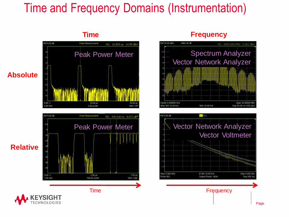
Time and Frequency Domains (Instrumentation)
9
Time Frequency
Peak Power Meter
Peak Power Meter
Spectrum Analyzer
Vector Network Analyzer
Vector Network Analyzer
Vector Voltmeter
Time Frequency
Absolute
Relative
© Keysight Technologies 2015
Page
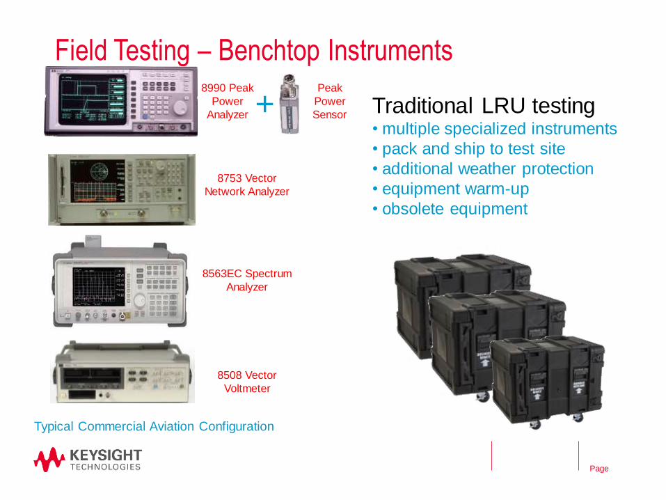
Field Testing – Benchtop Instruments
10
Traditional LRU testing • multiple specialized instruments
• pack and ship to test site
• additional weather protection
• equipment warm-up
• obsolete equipment
8990 Peak
Power
Analyzer
8753 Vector
Network Analyzer
8563EC Spectrum
Analyzer
8508 Vector
Voltmeter
Typical Commercial Aviation Configuration
Peak
Power
Sensor +
© Keysight Technologies 2015
Page
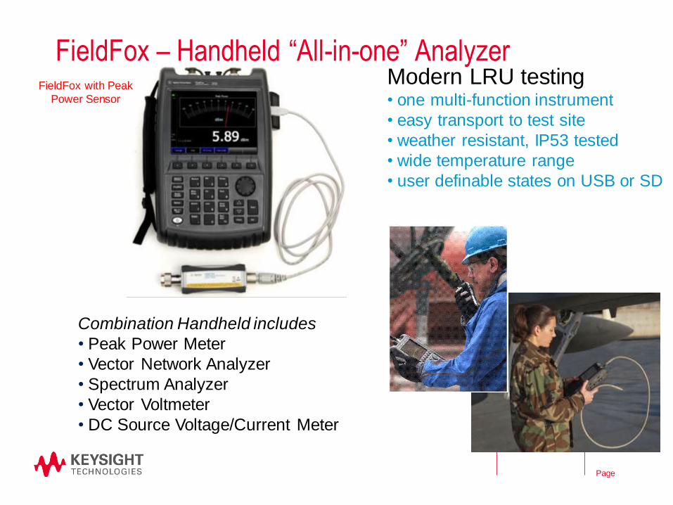
FieldFox – Handheld “All-in-one” Analyzer
11
Modern LRU testing • one multi-function instrument
• easy transport to test site
• weather resistant, IP53 tested
• wide temperature range
• user definable states on USB or SD
FieldFox with Peak
Power Sensor
Combination Handheld includes
• Peak Power Meter
• Vector Network Analyzer
• Spectrum Analyzer
• Vector Voltmeter
• DC Source Voltage/Current Meter
© Keysight Technologies 2015

Page
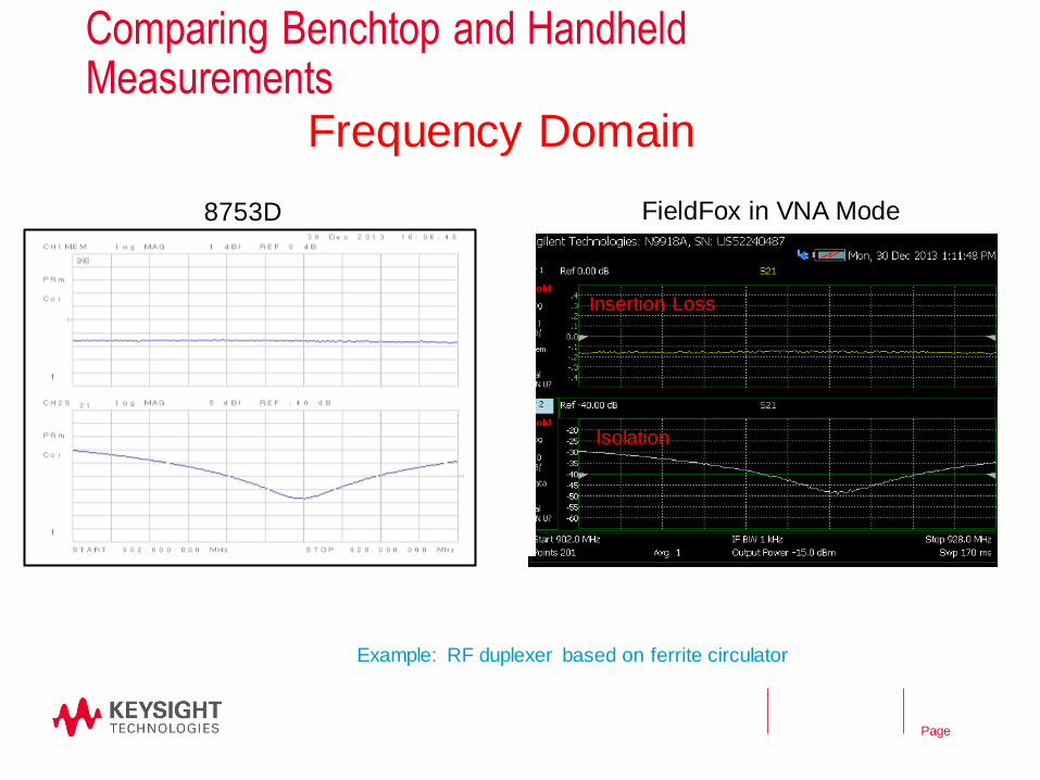
Comparing Benchtop and Handheld Measurements
12
Example of Mode S transmitter showing P2-to-P6 first sync phase reversal
P1 P2 P6
8990A FieldFox in Pulse Mode
Time Domain
© Keysight Technologies 2015
Page
Comparing Benchtop and Handheld Measurements
13
8753D FieldFox in VNA Mode
Insertion Loss
Isolation
Frequency Domain
Example: RF duplexer based on ferrite circulator
© Keysight Technologies 2015
Page
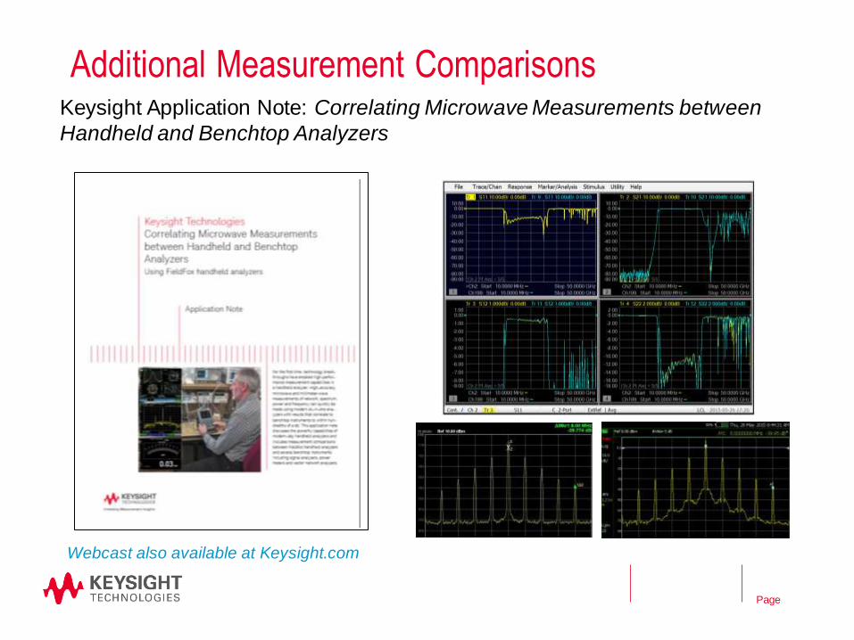
Additional Measurement Comparisons
14
Keysight Application Note: Correlating Microwave Measurements between
Handheld and Benchtop Analyzers
Webcast also available at Keysight.com
© Keysight Technologies 2015
Page
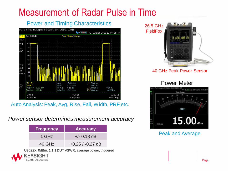
Measurement of Radar Pulse in Time
15
Auto Analysis: Peak, Avg, Rise, Fall, Width, PRF,etc.
26.5 GHz
FieldFox
40 GHz Peak Power Sensor
Power and Timing Characteristics
Power Meter
Power sensor determines measurement accuracy
Peak and Average Frequency Accuracy
1 GHz +/- 0.18 dB
40 GHz +0.25 / -0.27 dB
U2022X, 0dBm, 1.1:1 DUT VSWR, average power, triggered
© Keysight Technologies 2015

Page
ATCRBS Transmitter Timing Offset
16
1. Trigger peak power sensor
2. Measure Primary data (memory)
3. Measure Auxiliary data
4. Markers for timing difference
P1 P3
P2
TTL In
FieldFox
U2021X Peak Sensor
FieldFox in Pulse Mode
TTL In
P1 P2 P3
© Keysight Technologies 2015
Page
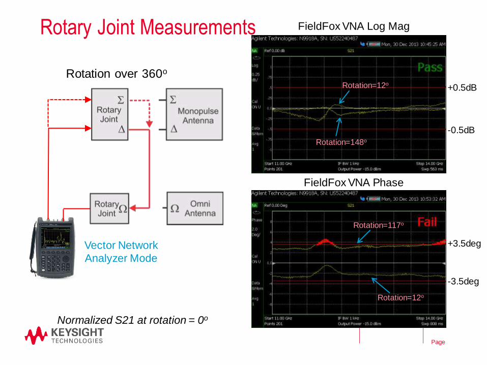
Rotary Joint Measurements
17
+0.5dB
-0.5dB
+3.5deg
-3.5deg
Vector Network
Analyzer Mode
Rotation=12o
Rotation=148o
Rotation=12o
Rotation=117o
FieldFox VNA Log Mag
FieldFox VNA Phase
Rotation over 360o
Normalized S21 at rotation = 0o
© Keysight Technologies 2015
Page
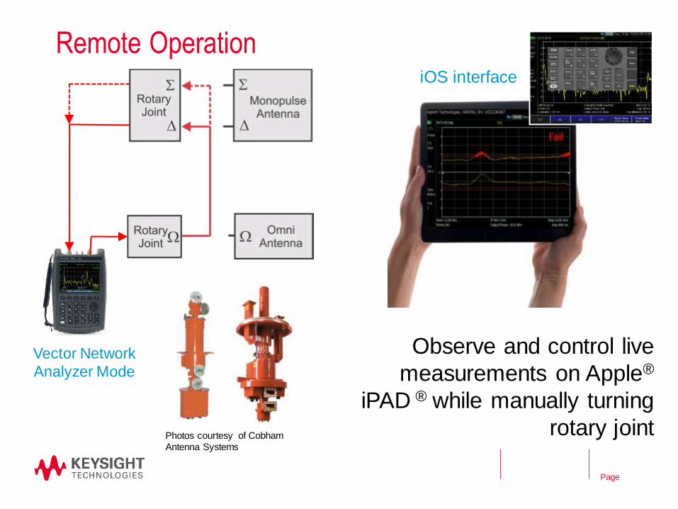
Remote Operation
18
Observe and control live
measurements on Apple®
iPAD ® while manually turning
rotary joint
Vector Network
Analyzer Mode
iOS interface
Photos courtesy of Cobham
Antenna Systems
© Keysight Technologies 2015
Page
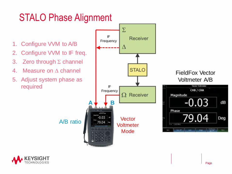
STALO Phase Alignment
19
A B
FieldFox Vector
Voltmeter A/B
1. Configure VVM to A/B
2. Configure VVM to IF freq.
3. Zero through S channel
4. Measure on D channel
5. Adjust system phase as
required
Vector
Voltmeter
Mode
A/B ratio
IF
Frequency
IF
Frequency
© Keysight Technologies 2015
Page
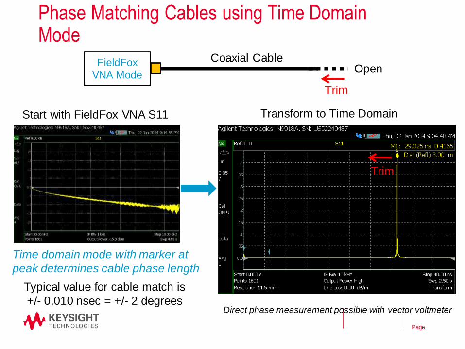
Phase Matching Cables using Time Domain Mode
20
Start with FieldFox VNA S11 Transform to Time Domain
Time domain mode with marker at
peak determines cable phase length
Open Coaxial Cable FieldFox
VNA Mode
Trim
Trim
Typical value for cable match is
+/- 0.010 nsec = +/- 2 degrees Direct phase measurement possible with vector voltmeter
© Keysight Technologies 2015
Page
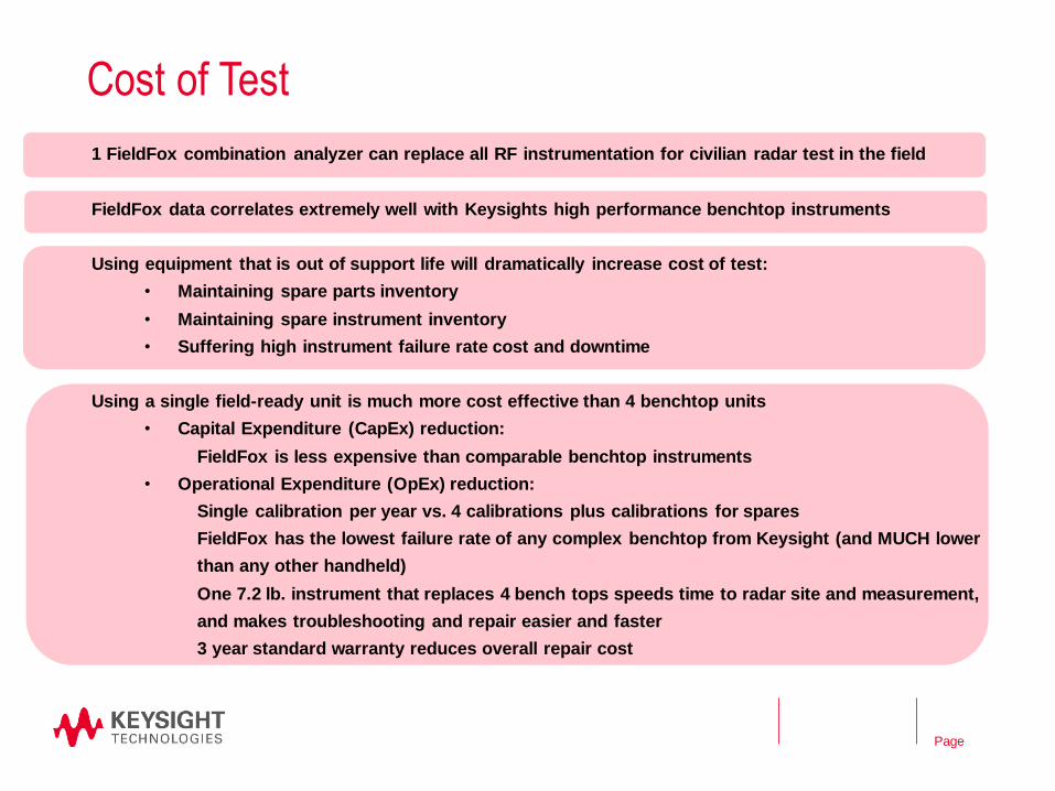
Cost of Test
1 FieldFox combination analyzer can replace all RF instrumentation for civilian radar test in the field
FieldFox data correlates extremely well with Keysights high performance benchtop instruments
Using equipment that is out of support life will dramatically increase cost of test:
• Maintaining spare parts inventory
• Maintaining spare instrument inventory
• Suffering high instrument failure rate cost and downtime
Using a single field-ready unit is much more cost effective than 4 benchtop units
• Capital Expenditure (CapEx) reduction:
FieldFox is less expensive than comparable benchtop instruments
• Operational Expenditure (OpEx) reduction:
Single calibration per year vs. 4 calibrations plus calibrations for spares
FieldFox has the lowest failure rate of any complex benchtop from Keysight (and MUCH lower
than any other handheld)
One 7.2 lb. instrument that replaces 4 bench tops speeds time to radar site and measurement,
and makes troubleshooting and repair easier and faster
3 year standard warranty reduces overall repair cost
21
© Keysight Technologies 2015
Page
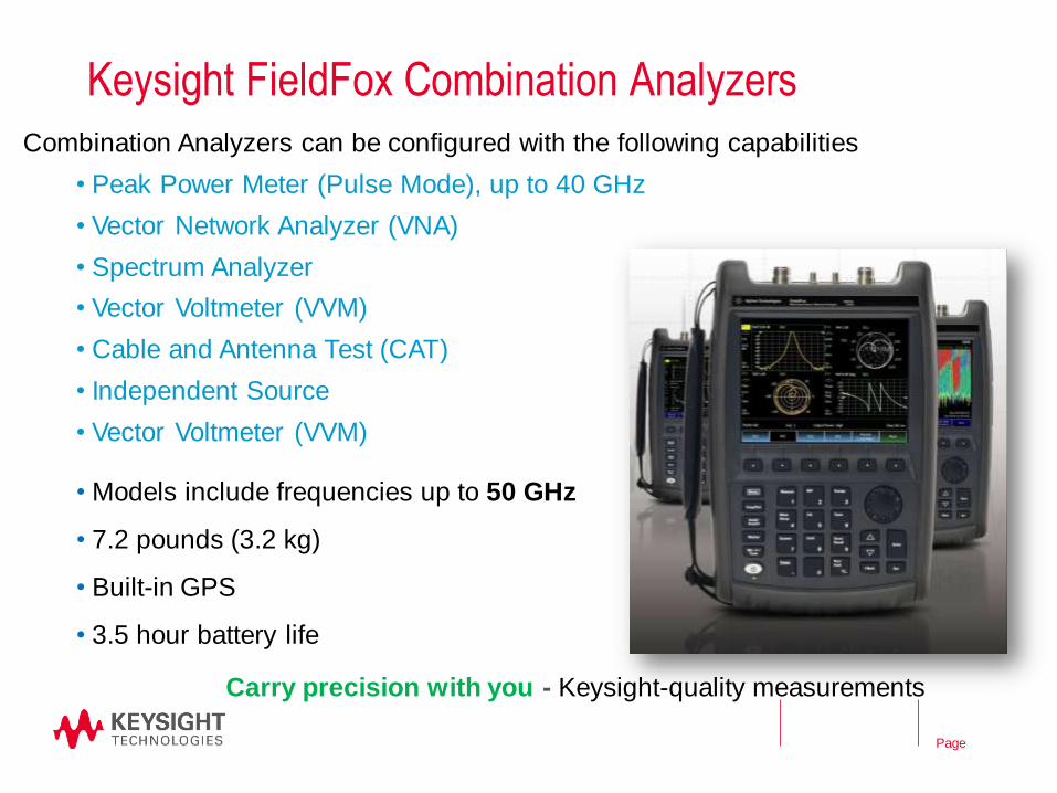
Combination Analyzers can be configured with the following capabilities
• Peak Power Meter (Pulse Mode), up to 40 GHz
• Vector Network Analyzer (VNA)
• Spectrum Analyzer
• Vector Voltmeter (VVM)
• Cable and Antenna Test (CAT)
• Independent Source
• Vector Voltmeter (VVM)
Keysight FieldFox Combination Analyzers
• Models include frequencies up to 50 GHz
• 7.2 pounds (3.2 kg)
• Built-in GPS
• 3.5 hour battery life
Carry precision with you - Keysight-quality measurements
22
© Keysight Technologies 2015
Page
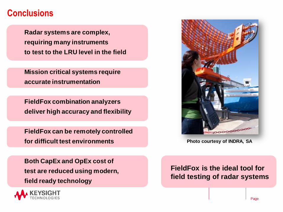
Conclusions
23
Radar systems are complex,
requiring many instruments
to test to the LRU level in the field
Mission critical systems require
accurate instrumentation
FieldFox combination analyzers
deliver high accuracy and flexibility
FieldFox can be remotely controlled
for difficult test environments
Both CapEx and OpEx cost of
test are reduced using modern,
field ready technology
Photo courtesy of INDRA, SA
FieldFox is the ideal tool for
field testing of radar systems
© Keysight Technologies 2015
Page
For More Information
Contact : Tom Hoppin, [email protected]
Web: www.keysight.com/find/FieldFox
Literature: FieldFox Handheld Analyzers, brochure, literature number 5990-9779EN
Thank you for your time
Questions?
7th in a series of application webcasts
• Sept 26, 2012: Interference Testing
• Oct 24, 2012: Cable and Antenna Measurements
• Nov 28 2012: Calibration and Alignment
• Jan 23 2013: Time Domain Measurements
• Mar 27 2013: Precise Power Measurements
• Jul 24 2013: Precise Data Correlation
Registration: www.keysight.com/find/FieldFoxWebcasts
24
© Keysight Technologies 2015
Page
References • Gertz, J. L., “Project Report ATC-65, The ATCRBS Mode of DABS,” FAA-RD-76-39, Lincoln Laboratory, January 31, 1977
• Orlando, V.A., “The Mode S Radar Beacon System,” The Lincoln Laboratory Journal, Volume 2, Number 3 , 1989
• Karp, D., Wood, M. L., “Project Report ATC-72, DABS Monopulse Summary,” FAA-RD-76-219, Lincol Laboratory,
February 4, 1977
• Keysight Application Note, Techniques for Precise Interference Measurements in the Field Using FieldFox handheld
analyzers, Literature Number 5991-0418EN, February 2013
• Keysight Application Note, Techniques for Precise Cable and Antenna Measurements in the Field Using FieldFox
handheld analyzers, Literature Number 5991-0419EN, June 2013
• Keysight Application Note, Techniques for Time Domain Measurements Using FieldFox handheld analyzers, Literature
Number 5991-0420EN, March 2013
• Keysight Application Note, Techniques for Precise Calibrations in the Field Using FieldFox handheld analyzers, Literature
Number 5991-0421EN, February 2013
• Keysight Application Note, Techniques for Precise Power Measurements in the Field Using FieldFox handheld analyzers,
Literature Number 5991-0423EN, July 2013
• Keysight Application Note, Correlating Microwave Measurements between Handheld and Benchtop Analyzers, Literature
Number 5991-0422EN, November 2013
• Keysight U2020 X-Series USB Sensor Uncertainty Calculator - Application Note : Measurement Uncertainty Calculator for
U2020 X-Series found at http://www.home.keysight.com. Search for “uncertainty calculator”
25
© Keysight Technologies 2015