Embed Size (px)
Citation preview

PRECISIONSURFACE
EQUIPMENT
A Guide to the complete Challenge line of equipment for:
• Precision Layout and Inspection• Tooling• Workholding• Fixture Components• Machine Bases
Expanded to include specifications, configurations, and more.

Page 2
CHALLENGE PRECISION SURFACE EQUIPMENT —
— Is made of 30,000 P.S.I. minimum Gray Iron. Qualities include strength, toughness, wear resistance, solidity, a high retention of dimensionalaccuracy in service, a low coefficient of friction, and a relatively high density.
— Is easily machinable for adding mounting, workholding, or measuring features.
— Is guaranteed accurate to the tolerances shown. Accuracy is determined using precision measuring equipment.
— Increased capacity to run your special needs in cast iron, aluminum, bronze, steel, stainless steel, zirconium, alloy, and other exotics thru our CNCMills & Lathes and Wire EDM. We also do prototypes and short run production.
Before ordering, contact Challenge to be sure you have the current catalog and price information. Call for pricing on calibration services. All pricesand specifications are subject to change without notice.
MAILING & REMIT TO ADDRESSChallenge Precision5677 Airline RoadFruitport, Michigan 49415
SHIPPING ADDRESSChallenge Precision5677 Airline RoadFruitport, Michigan 49415Cast Iron and Granite are shipped prepaid and addunless otherwise requested.
OFFICE HOURS8:00 A.M. - 5:00 P.M.Eastern Standard Time
PHONE NUMBERSTelephone: (231) 865-6944Fax: (231) 865-8887
WEBSITEWWW.CHALLENGEPRECISION.COM
TELEPHONE ORDERSOrders placed on equipment by telephone must be followed by a writtenconfirming order. Challenge Precision cannot be responsible forequipment furnished incorrectly if a confirming order is not supplied.
BUYER WARRANTYThis equipment is guaranteed to be free of defects in workmanship ormaterial for a period of one year from date of invoice. We will repair orreplace, at our option, any equipment proving defective not caused byaccident, misuse, or improper maintenance. Should you find anythingwrong, contact the Sales Manager of Precision Products. Challenge willnot be responsible for any charges incurred without specificauthorization.
SHORT FORM CERTIFICATIONProvided free of charge when requested at the time of order placement.A $50.00 NET per piece charge will be added if request is made aftershipment.OPTION: Long form certification, $150.00 NET per piece at time of orderplacement only.
RETURNSNo merchandise will be accepted for credit without written authorizationfrom Challenge Precision. Any purchases not returned within 90 daysfrom date of invoice are not returnable. Prior to any merchandise beingreturned you must receive a Return Authorization Form. Any returnedmerchandise that was correctly supplied according to the customer’sorder, a 20% handling charge will be made to cover the cost of inspectingand repackaging. If reconditioning is necessary, the net cost of suchwork will be deducted from the credit issued. Include a copy ofChallenge’s Return Authorization Form, plus a packing list withyour equipment. All returned merchandise must be shipped FREIGHTCHARGES PREPAID and packaged properly. Any material returnedwithout prior approval will be refused and returned to customerwith freight charges COLLECT.
TERMS1/2 % 10 Days - Net 30 days.
PACKINGA $6.00 packaging fee will be applied to all orders for standardcommercial packing.
EXPORTFor shipments outside the continental United States add export packingcharges (furnished on request), freight charges to Port of Exit, dockcharges, insurance, brokerage, ocean freight, import duties, and othercharges that are applicable.
DAMAGE IN TRANSITAccording to I.C.C. regulations, title and ownership of equipment passesto the consignee as soon as a shipment is given by the manufacturer tothe carrier. Challege Precision cannot make claims for damage or loss inshipment. Please inspect the goods and boxes carefully prior tosigning the Bill of Lading. Upon signing the Bill of Lading for thegoods, according to I.C.C. regulations, they are considered tobe received in an acceptable condition unless otherwise notedon the Bill of Lading. If box is damaged, sign for goods asdamaged and request the carrier to inspect the goods. CLAIMSMUST BE MADE BY THE COMPANY RECEIVING THE SHIPMENT.

Page 3
INDEX
MISCELLANEOUS:CALIBRATION SERVICE ................................................................................. 4TOLERANCES ................................................................................................ 5T-SLOT DIMENSIONS ..................................................................................... 5
ANGLE PLATES:STANDARD ANGLE PLATES .......................................................................... 6SLOTTED INSIDE/OUTSIDE ANGLE PLATES ................................................ 7UNIVERSAL RIGHT ANGLE IRONS ................................................................. 7SLOTTED ANGLE PLATES .......................................................................... 8-9T-SLOTTED ANGLE PLATES ....................................................................... 10STACKED BOX ANGLE PLATES ................................................................... 11
BLOCKS:BOX PARALLELS .......................................................................................... 12V-BLOCKS .................................................................................................... 13TOOLING BLOCKS ....................................................................................... 14HEIGHT BLOCKS .......................................................................................... 14
STRAIGHT EDGES ...................................................................................... 15
PLATES:LAPPING PLATES ......................................................................................... 16SOLID TOOLING BASES .............................................................................. 162” CORED BENCH PLATES ......................................................................... 174” CORED BENCH PLATES ......................................................................... 1810” x 14” DUPLEX BENCH BLOCKS............................................................. 196” CLAMP EDGE PLATES ............................................................................. 19THREE POINT SURFACE PLATES ............................................................... 19STANDARD 6” LAYOUT PLATES .................................................................. 20LAYOUT PLATE STANDS .............................................................................. 216” FLOOR PLATES ....................................................................................... 22STEEL WELDMENTS ................................................................................... 2350” x 70” MACHINE LAYOUT PLATE .............................................................. 23
GRANITE PRECISION SURFACE EQUIPMENT:SURFACE PLATES ....................................................................................... 24SURFACE PLATE STANDS ........................................................................... 25ACCESSORIES:- ANGLE PLATES, STRAIGHT EDGES, AND PARALLELS ............................ 26- V-BLOCKS, MASTER SQUARES & ANGLES, AND CUBES....................... 27
Page 4
LASER CALIBRATION SERVICES
HELPING OUR CUSTOMERS DELIVER QUALITY ASSURANCECount on Challenge for expert laser calibration services.Using the Hewlett-Packard and Hamar Laser systems, wecheck and certify the linear positioning of machining centersand the flatness of layout plates and large machinedsurfaces. Both activities are critical steps to meeting strictquality standards, and earning certification or recertification.
Serving Major Clients• NASA• Boeing• Ford• General Motors• Nissan• Saturn• Toyota
Meeting Quality Requirements• Ford Q1• General Motors TFE• Chrysler Pentastar• Caterpillar AQI
Offering Calibration Services for• Floor plates• Bench plates• Layout plates• Three-point surface plates• CMM bases• Machine tables, bases, and beds• Linear positioning of machine tools• Call for special applications
Accomplishing Your Objectives• Installation• Certification• Annual recertification

Page 5
T-SLOT DIMENSIONS
WORKING SURFACE NON-WORKING SURF.
STANDARD ANGLE
SLOTTED ANGLE
L-SHAPEST-SLOTTED ANGLE
(ANGLES)INSIDE-OUTSIDE ANGLE ±.030"
UNIVERSAL ANGLE IRON ±.010"
UNIVERSAL BOX ANGLE
BOX PARALLEL ±.0005"
BOXHEIGHT BLOCKS
SHAPESPARALLEL STRAIGHT EDGE .00075" IN 72"
(BLOCKS) STACKED BOX ANGLEMACH. FINISH
MANUFACTURING PRACTICES AND TOLERANCES MAXIMUM GRINDING HEIGHTCAPACITY = 28"
SQUARE
(STANDARDS)
FLATNAME PARALLEL
±.030
NON APPLICABLE
±.030"
GROUND FINISH UNLESSOTHERWISE SPECIFIED
SIZE
PER INCH OVER 6"
NON APPLICABLE
±.030".001" IN 12".002"
.00025" IN 6"
AND GRADUATED TO .0001
WITHIN .0005" UP TO 6"
A B ET-SLOT THROA T MAX. MAX.
SIZE DEPTH BASIC BASIC3/8 .437 11/32 21/64 19/64 25/32 23/32 1-1/21/2 .562 7/16 25/64 23/64 31/32 29/32 1-5/85/8 .687 9/16 31/64 29/64 1-1/4 1-3/16 1-7/83/4 .812 11/16 5/8 19/32 1-15/32 1-3/8 2-1/81 1.062 7/8 53/64 25/32 1-27/32 1-3/4 2-1/2
1-1/4 1.312 1-1/8 1-3/32 1-1/32 2-7/32 2-1/8 31-1/2 1.562 1-3/8 1-11/32 1-9/32 2-21/32 2-9/16 3-1/2
C D
±.010 MIN. MIN.
PRODUCTS MADE FROM CAST IRON CASTINGS.
FOR ADDITIONAL PHYSICAL PROPERTIES &SPECIFICATIONS, CONTACT CHALLENGE PRECISION
TOLERANCES
These are standard tolerances. Specials are available. Please contact Challenge Precision for availability.
2
3
1
2
3
4
4
2
1
3
ALL CHARTED DIMENSIONS ARE WITHINAMERICAN STANDARD T-SLOTREQUIREMENTS.
C.M.C. CLOSEST TOLERANCE ±.001.
C.M.C. STANDARD MICRO INCH FINISH.
C.M.C. STANDARD MATERIAL THICKNESS.
NOTES:

Page 6
STANDARD ANGLE PLATES
APPLICATIONS A practical, versatile means of clamping and holdingwork in a vertical postion for layout, machining, and inspection, or for avertical reference. Also ideal for use as time-saving, reusable fixturecomponents.
GENERAL SPECIFICATIONS Heavily ribbed for strength and rigidity.The sides and ends are machined finished.
TOLERANCES The two outside working surfaces are precision groundflat & square to within .0005” in 6” and graduated to .0001” in 1” thereafter.
OPTIONS Sides and ends can be precision ground. Matched pairs alsoavailable. Matching refers to overall dimensions only.
DIMENSIONS
SIZE (Inches) PART APPROXIMATEAxBxC NUMBER SHIPPING WGHT
2 x 2 x 2 AP-020202 2 lbs / 1 kg2-3/4 x 4-3/4 x 4-3/4 AP-02H04H04H 7 lbs / 3 kg3 x 3 x 3 AP-030303 4 lbs / 2 kg3-1/2 x 4 x 4 AP-03E0404 7 lbs / 3 kg4 x 4 x 4 AP-040404 7 lbs / 3 kg4 x 5 x 6 AP-040506 12 lbs / 5 kg5 x 5 x 5 AP-050505 14 lbs / 6 kg6 x 6 x 6 AP-060606 20 lbs / 9 kg6 x 6 x 8 AP-060608 26 lbs / 12 kg6 x 8 x 6 AP-060806 28 lbs / 13 kg6 x 8 x 10 AP-060810 48 lbs / 22 kg8 x 8 x8 AP-080808 45 lbs / 20 kg8 x 10 x 6 AP-081006 45 lbs / 20 kg8 x 10 x 12 AP-081012 85 lbs / 38 kg12 x 12 x 12 AP-121212 130 lbs / 59 kg12 x 16 x 16 AP-121616 265 lbs / 119 kg12 x 24 x 24 AP-122424 410 lbs / 185 kg18 x 18 x 18 AP-181818 345 lbs / 155 kg24 x 24 x 24 AP-242424 870 lbs / 390 kg
OVERALL THICK THICK EDGE SIDE BTWNAxBxC D No. E F G H2 x 2 x 2 1/2 1 1/2 3/4 - -2-3/4 x 4-3/4 x 4-3/4 1/2 1 1/2 3/4 - -3 x 3 x 3 1/2 1 1/2 1/2 - -3-1/2 x 4 x 4 1/2 1 1/2 1/2 - -4 x 4 x 4 1/2 1 1/2 3/4 - -4 x 5 x 6 5/8 1 1/2 5/8 - -5 x 5 x 5 5/8 1 1/2 5/8 - -6 x 6 x 6 3/4 1 1/2 3/4 - -6 x 6 x 8 3/4 2 1/2 1 2 46 x 8 x 6 1 1 3/4 1-1/4 - -6 x 8 x 10 1 2 3/4 1-1/4 2-1/2 58 x 8 x8 1-1/4 2 1/2 1 2 48 x 10 x 6 1-1/4 1 3/4 1-1/2 - -8 x 10 x 12 1-1/4 2 3/4 1-1/2 3 612 x 12 x 12 1-3/8 2 3/4 1-3/8 3 612 x 16 x 16 1-1/2 2 3/4 1-3/4 4 812 x 24 x 24 2-3/8 & 1-1/2 2 1 2 & 7/8 6 1218 x 18 x 18 1-1/4 2 1 1-1/2 6 624 x 24 x 24 2 3 1 2-1/4 4 8
DIMENSIONS RIB SPECIFICATIONS

Page 7
SLOTTED INSIDE/OUTSIDEANGLE PLATES
UNIVERSAL RIGHT ANGLEIRONS
APPLICATIONS Inside-outside angle plates are versatile accessorieswhich can be used to clamp and hold work in a vertical position for planing,milling, or drilling. Work can be clamped and rotated through severalplanes for measurement or machining without repositioning.
The slots allow work to be easily fastened to the plate, and the plate to afixture base or machine bed.
The inside corner is relieved so that a 90° work piece can be nested flatand square against the inner edges.
TOLERANCES The inside and outside working surfaces, and sides andends are precision ground flat & square within .0005” up to 6” andgraduated to .0001” per inch thereafter. Inside and outside faces areparallel within .00025” in 6”.
OPTIONS Matched pairs. Matching refers to overall dimensions only.
APPLICATIONS Work can be clamped to either face for measurementor machining and rotated through three planes without the need forreclamping. Can be used as fixture components or for checkingsquareness and parallelism.
TOLERANCES All faces, sides, and ends are precision ground parallelwithin .00025” in 6”, flat & square within .0005” in 6”, and graduated .0001”per inch thereafter.
OPTIONS Matched pairs available. Matching refers to overall dimensionsonly.
DIMENSIONS
DIMENSIONS
FIG. A
SIZE (Inches) PART APPROX. SEEAxBxC NUMBER SHIPPING WT. FIG.4x4x4 AI-040404 9 lbs / 4 kg B6x6x6 AI-060606 24 lbs / 11 kg B6x7x8 AI-060708 39 lbs / 18 kg A
U P R T BOTH B A S E T O BETW TOP B A S E
LENGTH WIDTHS LENGTH SIDE SLOTS EDGE EDGE
AxBxC D E F G H I J K6x7x8 1-1/2 2-1/4 9/16 3 2 4 1-1/4 1-1/2
SLOT SIZE SLOT LOCATION
ANGLE SIZE
FIGURE A
UP R T B O T H B A S E T O T O P B A S E
L E N G T H WID T H S L E N G T H S I D E ED G E E D G E
AxBxC D E F G H I J4x4x4 1 1-3/8 7/16 1-3/8 2 7/8 7/86x6x6 1-1/4 1-1/4 9/16 2-1/2 3 1-1/4 1-1/4
SLOT SIZE SLOT LOCATION
ANGLE S IZE
FIGURE B
SIZE (Inches) PART APPROX.AxBxC NUMBER SHIPPING WT.4x5x4 AU-040504 11 lbs / 5 kg5x8x5 AU-050805 23 lbs / 10 kg6x8x6 AU-060806 32 lbs / 14 kg6x12x6 AU-061206 52 lbs / 23 kg8x10x6 AU-081006 40 lbs / 18 kg9x16x8 AU-091608 100 lbs / 45 kg10x18x12 AU-101812 155 lbs / 70 kg12x12x12 AU-121212 125 lbs / 56 kg12x24x12 AU-122412 270 lbs / 122 kg16x24x14 AU-162414 395 lbs / 178 kg
SIZE (Inches) BASE UPRIGHT RIBAxBxC D E F4x5x4 3/4 3/4 3/45x8x5 7/8 7/8 16x8x6 1 1 16x12x6 1-1/4 1-1/4 1-1/28x10x6 7/8 7/8 19x16x8 1-1/4 1-1/4 1-1/410x18x12 1-1/4 1-1/4 1-1/412x12x12 1-3/8 1-3/8 1-3/412x24x12 1-3/8 1-3/8 1-3/416x24x14 1-3/4 1-3/4 1-3/4
Page 8
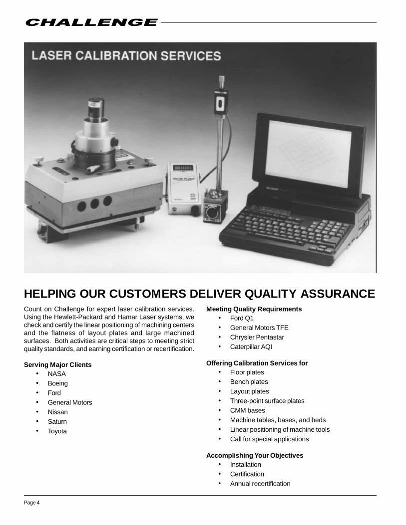
SLOTTED ANGLE PLATES
APPLICATIONS Slotted angle plates can be used for rapid mountingfixtures for machine set-up, layout, or inspection.
They are heavily ribbed for strength and rigidity.
Sides and ends are machine finished.
TOLERANCES The two outside working surfaces are precision groundflat & square to within .0005” up to 6” and graduated to .0001” per inchthereafter.
OPTIONS Side and ends can be precision ground. Matched pairs alsoavailable. Matching refers to overall dimensions only.
DIMENSIONS
FIG. A
FIG. B
FIG. C
TO B E T V E R T SLOT B A S E TO BET. TO
THCK SIDE RIBS LGTH W D T H LGTH SIDE SLOT EDGE
AxBxC D E F G H I J K L M5x6x12 3/4 1/2 3 6 3-1/4 9/16 2-1/4 1-3/8 4-5/8 1
SLOT LOC.RIBS SLOT SIZE
ANGLE S IZE
FIGURE C
TO VER. SLOT BASE TO TO TO TO
THCK SIDE BET LGTH WTH LGTH BET SIDE EDGE SIDE EDGE
AxBxC D E F G H I J K L M N O4x5½x5 5/8 1/2 1/2 4 3 9/16 2-1/2 2 1-1/2 1 1-1/4 1-3/49x10x12 1 3/4 2-3/8 7-1/4 6-1/2 11/16 4-3/4 4 4 1-1/2 3-5/8 4
ANGLE SIZE
FIGURE B UPRIGHT SLOT BASE SLOTRIBS SLOT SIZE
T O V E R . B O T H B A S E T O TO
THICK SIDE B E T LGTH W I D T H LGTH SIDE EDGE
AxBxC D E F G H I J K L4x5x9 5/8 1/2 2-1/4 4-1/2 3 9/16 2 4-1/2 3/4
8x12x10 1-1/4 3/4 2-1/2 5 8 11/16 4 5 1-1/2
SLOT LOC.RIBS SLOT SIZE
ANGLE SIZE
FIGURE A
SIZE (Inches) PART APPROX. SEEAxBxC NUMBER SHIPPING WT. FIG.4x5-1/2x5 AS-0405E05 11 lbs / 5 kg B5x6x12 AS-050612 35 lbs / 16 kg C6x8x6 AS-060806 25 lbs / 11 kg D8x12x10 AS-081210 88 lbs / 40 kg A9x10x12 AS-091012 80 lbs / 36 kg B12x14x16 AS-121416 205 lbs / 92 kg E16x18x20 AS-161820 305 lbs / 137 kg F18x24x12 AS-182412 340 lbs / 153 kg G

Page 9
SLOTTED ANGLE PLATES
FIG. D
FIG. E
FIG. F
FIG. G
TO B E T V E R T SLOT BASE TO B T W TO
THCK SIDE RIBS LGTH WDTH LGTH SIDE SLOT EDGE
AxBxC D E F G H I J K L M12x14x161-3/8 3/4 2 2/3 5 1/3 10 13/16 8 5-1/2 5 1-1/2
SLOT LOC.RIBS SLOT SIZE
ANGLE SIZE
FIGURE E
T O V E R T SLOT BOTH T O B T W T O
THICK SIDE LNGTH W D T H W D T H SIDE SLOT EDGE
AxBxC D E F G H I J K L6x8x6 1 3/4 3 5-1/4 11/16 3-1/4 1-5/16 3-3/8 1
SLOT LOC.RIBS SLOT SIZE
ANGLE S IZE
FIGURE D

Page 10
APPLICATIONS T-slotted angle plates are used for accurately holdingwork on a vertical plane for precision boring, milling, or drilling operations.
One-piece construction with heavy support ribbing to help preventdistortion under heavy loads.
TOLERANCES The two outside working surfaces are:* PRECISION GROUND: Flat & square within .0005” per 6” and .0001”
every inch thereafter, not to exceed a maximum of .001”.** MACHINE FINISHED: Flat & square within .002” T.I.R. overall.*** MACHINE FINISHED: Flat & square within .005” T.I.R. overall.
OPTIONS Vertical and/or horizontal T-slots, drilled and tapped holes, orlocating keyways.
T-SLOTTED ANGLE PLATESDIMENSIONS
FIG. B
FIG. C
FIG. A
RIB SPECIFICATIONS (FIGURES B & C)# O F R IB T O B T W N SEE
R I B S T H I C K SID E SLOT FIG.
AxBxC - D E F -6x12x12 2 1 3 6 B12x18x18 2 1 4 10 B12x24x24 2 1 6 12 B18x36x18 2 1-1/4 3 12 B18x36x36 3 1-1/4 6 12 C24x36x36 3 1-1/4 6 12 C24x48x48 3 1-1/2 6 18 C24x60x18 2 1-1/2 3 12 B36x72x36 3 1-1/4 6 12 C48x72x24 2 1-1/2 4 16 B
A N G L E S I Z E
SIZE (Inches) PART APPROX.AxBxC NUMBER SHIPPING WT.
*6x12x12 AT-061212-1 130 lbs / 59 kg*12x18x18 AT-121818-1 365 lbs / 165 kg*12x24x24 AT-122424-1 600 lbs / 270 kg**18x36x18 AT-183618 1010 lbs / 455 kg**18x36x36 AT-183636 1750 lbs / 790 kg**24x36x36 AT-243636 2335 lbs / 1050 kg***24x48x48 AT-244848 3130 lbs / 1410 kg***24x60x18 AT-246018 1465 lbs / 600 kg***36x72x36 AT-367236 5280 lbs / 2375 kg***48x72x24 AT-487224 4700 lbs / 2115 kg
UP R T B A S E # O F SLOT B T W N T O
T H I C K T H I C K SLOTS SIZE SLOT E D G E
AxBxC D E - - F G6x12x12 2-1/4 1-1/4 2 5/8 4 412x18x18 2-1/2 2 3 5/8 6 312x24x24 2-3/8 1-1/2 3 5/8 6 618x36x18 2-15/16 1-3/4 5 3/4 6 618x36x36 2-15/16 1-3/4 5 3/4 6 624x36x36 3 2 5 3/4 6 624x48x48 3-3/8 2 7 1 6 624x60x18 3-1/4 2-1/4 9 3/4 6 636x72x36 3-1/2 3-1/2 11 3/4 6 648x72x24 3 3 11 1 6 6
ANGLE S IZE
FIGURE A

Page 11
STACKED BOX ANGLE PLATES
APPLICATIONS Box angles are work-holding fixtures for precisionmachining large work pieces on planer or boring mill operations. Theycan be used singly or in combination.
Vertical and horizontal T-slots provide a convenient means of clampingthe work pieces.
A locating keyway is provided on the top and bottom surfaces foraccurate alignment with each other and with the machine bed.
TOLERANCES The two outside working surfaces are:** MACHINE FINISHED: Flat & square within .002” T.I.R. overall.*** MACHINE FINISHED: Flat & square within .005” T.I.R. overall.
OPTIONS Sizes other than shown are available on special order.
DIMENSIONS
SIZE (Inches) PART APPROX.AxBxC NUMBER SHIPPING WT.**15x12x12 BA-151212 260 lbs / 118 kg**15x24x12 BA-152412 510 lbs / 232 kg**24x36x18 BA-243618 1200 lbs / 545 kg***30x48x24 BA-304824 2700 lbs / 1226 kg***30x60x24 BA-306024 3375 lbs / 1532 kg
# O F
ANGLE SIZE H O R Z
AxBxC D E F G H J K SLOTS
15x12x12 3 1-1/4 1-1/4 3 6 2 8 215x24x12 3 1-1/2 1-1/2 3 6 2 8 424x36x18 3-1/2 2-1/4 2-1/4 3 6 4 10 630x48x24 3-1/2 2-1/4 2-1/4 3 6 6 12 830x60x24 3-1/2 2-1/4 2-1/4 3 6 6 12 10
S U R F A C E SLOT LOCATION
H O R I Z O N T A L V E R T I C A LTHICKNESS
Page 12
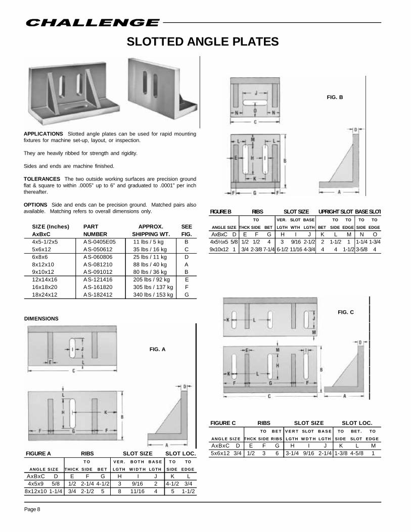
BOX PARALLELS
APPLICATIONS Box parallels are used for making fixtures, for mountingwork to be laid out or inspected, or in sets for raising work parallel to theworking surface.
TOLERANCES All sides are precision ground & parallel within .00025” in6”, flat & square within .0005” up to 6” and graduated to .0001” per inchthereafter.
Ends are machine finished.
OPTIONS Ends can be precision ground. Matched pairs also available.Matching refers to overall dimensions only.
DIMENSIONS
FIG. A
FIG. B
FIG. C
SIZE (Inches) PART APPROX. SEEAxBxC NUMBER SHIPPING WT. FIG.1½x2x4 BP-01E0204 3 lbs A3x4x6 BP-030406 12 lbs A4x4x6 BP-040406 16 lbs A4x6x6 BP-040606 20 lbs A5x8x12 BP-050812 68 lbs B5x10x10 BP-051010 70 lbs B6x6x6 BP-060606 27 lbs A6x12x12 BP-061212 100 lbs B6x14x16 BP-061416 145 lbs B8x8x8 BP-080808 60 lbs C10x10x10 BP-101010 125 lbs C12x12x12 BP-121212 220 lbs C
SIZE (Inches)AxBxC D1½x2x4 3/83x4x6 1/24x4x6 5/84x6x6 5/86x6x6 3/4
SIZE (Inches)AxBxC D5x8x12 3/45x10x10 3/46x12x12 3/46x14x16 3/4
SIZE (Inches)AxBxC D8x8x8 5/810x10x10 3/412x12x12 1

Page 13
V-BLOCKSAPPLICATIONS For supporting and holding cylindrical work for layout,machining, inspection, or as fixture components. A relief is provided inthe center of the V for drill clearance. FURNISHED IN PAIRS.
TOLERANCES The base, sides, and V are precision ground. The V iscentral, square with the sides, and parallel to the base within .0005”.
Ends are machine finished.
OPTIONS Ends can be precision ground. Matched pairs also available.Matching refers to overall dimensions only.
V-BLOCKS - SLOTTED FOR CLAMPS(Clamps included)
STANDARD V-BLOCKS
DIMENSIONS
Diametrical Capacity (D/C) can be increased by replacing standard clampbolts with threaded rod as below:
* D/C increases to 5-15/16” by adding threaded rod 6-1/4” long or more.** D/C increases to 9-5/8” by adding threaded rod 8-1/8” long or more.
CLAMP ASSEMBLIES
Size fits “C” dimension of V-Blocks shown at left.
“VCA” type “VTA” type
SIZE (Inches) PART APPROX.AxBxC NUMBER SHIPPING WT.2x2½x5 VS-0202E05 12 lbs3x3½x6 VS-0303E06 26 lbs6x6x7 VS-060607 84 lbs6x8x8 VS-060808 130 lbs12x12x12 VS-121212 420 lbs
SIZE PART NUMBER6" VCA-067" VCA-078" VTA-0812" VTA-12
SIZE (Inches) PART APPROX.AxBxC NUMBER SHIPPING WT.3x3½x6 VC-0303E06 32 lbs6x6x7 VC-060607 96 lbs
C R O S S V V
SIZE W A L L R I B R I B WIDTH D E P T H O P EN C L A M P
AxBxC D E F X Y Z Z2x2½x5 1/2 3/4 1 2-1/2 1-1/4 3-1/2 3-1/23x3½x6 5/8 1 1 3-1/2 1-3/4 4-3/4 4-3/46x6x7 3/4 1-1/8 1 4 2 5-1/2 5-1/26x8x8 3/4 1-1/4 1 5 2-1/2 7 *3-5/812x12x12 7/8 1-1/2 1-1/4 8-3/8 4-3/16 11-3/4 **6
D IA C A P A C ITY

Page 14
TOOLING BLOCKS HEIGHT BLOCKS
APPLICATIONS Challenge Tooling Blocks (Tombstones) provide apractical method of holding work accurately in a vertical or horizontalplane for CNC and NC machining operations. They can be mounteddirectly on the machine table or used in conjunction with rotary tables.The four working surfaces permit mounting of four work pieces at onetime. Quantity production jobs can be set up so that finished work piecescan be removed and new ones put in place while the machine is workingon the next piece.
TOLERANCES Base and sides milled flat, parallel & square to .001” per12”. Most sizes can be finished with a ground finish for tighter tolerancerequirements.
OPTIONS Other sizes and forms available. Mounting and positioningholes, T-slots, locating bushings, and other mounting features.
APPLICATIONS Used singly or in combination to provide an accuratereference plane parallel to and at the desired height from the workingsurface for gauging and measuring.
TOLERANCES The top and bottom surfaces are precision ground andaccurate in height to ±.0005” and parallel within .00025” within 6”.
OPTIONS Available in matched pairs within .00025” up to 10” or within.0005” up to 20”.
Blocks are approximately 7” square.
This is an example of how work can bemounted on the vertical and/or horizontalplanes of a tooling block for CNC or NC workon four identical items.
PART APPROX.HEIGHT NUMBER SHIPPING WT.5" BH-05 35 lbs / 16 kg10" BH-10 50 lbs / 23 kg15" BH-15 62 lbs / 28 kg20" BH-20 70 lbs / 32 kg
SIZE (Inches) PART APPROX.STYLE AxBxC BASE NUMBER SHIPPING WGT
9 x 22 x 9 13 x 13 x 1-3/4 BT-092209-3 470 lbs12 x 24 x 12 16 x 16 x 1-3/4 BT-122412-3 550 lbs14 x 26 x 14 18 x 18 x 1-3/4 BT-142614-3 720 lbs15 x 22 x 9 13 x 19 x 1-3/4 BT-152209-3 520 lbs18 x 30 x 18 22 x 22 x 2 BT-183018-3 1400 lbs20 x 32 x 9 17 x 24 x 2-1/4 BT-203209-3 975 lbs24 x 36 x 24 28 x 28 x 2-1/4 BT-243624-3 2375 lbs
Cub
e Ty
pe
SIZE (Inches) PART APPROX.STYLE AxBxC BASE NUMBER SHIPPING WGT
8 x 22 x 8 15.70 x 15.70 x 1.75 BT-082208-4 380 lbs10 x 26 x 10 15.70 x 15.70 x 1.75 BT-102610-4 485 lbs8 x 22 x 8 19.70 x 19.70 x 2 BT-082208-5 490 lbs
10 x 26 x 10 19.70 x 19.70 x 2 BT-102610-5 595 lbs4 x 18 x 15.70 15.70 x 15.70 x 1.75 BT-041815H-4 535 lbs4 x 24 x 15.70 15.70 x 15.70 x 1.75 BT-042415H-4 670 lbs4 x 18 x 19.70 19.70 x 19.70 x 2 BT-041819H-5 740 lbs4 x 24 x 19.70 19.70 x 19.70 x 2 BT-042419H-5 900 lbs
Cub
e Ty
pe"T
" Typ
e

Page 15
STRAIGHT EDGES PARALLEL STRAIGHTEDGES
APPLICATIONS Straight edges are widely used for checking theaccuracy of flat surfaces such as surface plates, machine tables, orways.
Furnished with leveling pads and wooden cover.
TOLERANCES Hand scraped accurate to .0002” overall.
APPLICATIONS Parallel straight edges are used for setting up andleveling machine tools, checking the flatness of surfaces, or forpositioning work above and parallel to a surface plate when checking orscribing parts. They are strongly ribbed for strength, with cored holesfor lightness and handling ease.
Wooden cover furnished.
TOLERANCES - Precision Ground: The top and bottom surfaces areprecision ground flat and parallel to within .0005” overall for the 36” & 48”and within .00075” for the 60” & 72”
TOLERANCES - Hand Scraped: The top and bottom surfaces are handscraped flat and parallel to within .0002” overall.
SIZE (Inches) PART APPROX.AxBxC NUMBER SHIPPING WT.24 x 1-5/8 x 5-1/8 ES-024-SC 23 lbs / 10 kg36 x 1-7/8 x 6 ES-036-SC 45 lbs / 20 kg48 x 2 x 6-1/4 ES-048-SC 55 lbs / 25 kg
SIZE (Inches) PRECISION HAND APPROX.AxBxC GROUND SCRAPED SHIPPING WT.36 x 2½ x 8 EP-036-GR EP-036-SC 98 lbs / 45 kg48 x 2½ x 8 EP-048-GR EP-048-SC 104 lbs / 47 kg60 x 2½ x 8 EP-060-GR Not Available 130 lbs / 59 kg72 x 2½ x 8 EP-072-GR Not Available 160 lbs / 73 kg
PART NUMBER

Page 16
LAPPING PLATESAPPLICATIONS These solid plates are used for deburring and finelapping of metal joints for an oil-tight fit.
SMALL RECTANGULAR
TOLERANCES Both sides are precision ground flat within .001” overall.On the 8 x 8 x 1 size, one surface is smooth; the other has 1/16” grooves,1/2” apart crossing at 90°. (See magnified detail below)
4” RECTANGULAR
TOLERANCES Top surface is precision ground flat within .0005” in 12”overall with 1/16” x 1/16” grooves, 1/2” apart crossing at 90°.
ROUND
TOLERANCES Top surface is precision ground flat within .0005” in 12”overall with 1/16” x 1/16” grooves, 1/2” apart crossing at 90°.
OPTION Steel handles.
SOLID TOOLING BASES
APPLICATIONS Provide solid, accurate, precision-machined bases foruse in N/C or standard machine fixturing, as tooling pallets or subplates,surface plates for layout and inspection, or optical bases.
OPTIONS Mounting holes drilled and tapped. Plates of matchedthickness available.
1” TOOLING BASES
TOLERANCES Top and bottom are precision ground flat and parallelwithin .001” overall.
Sides and ends are machine finished square and parallel within .005”overall.
NOTE: Will not normally hold accuracy in service unless supported by afirm, flat surface. Where an accurate surface is required, thicker coredplates are recommended.
2” TOOLING BASES
TOLERANCES Top and bottom are precision ground flat and parallelwithin .001” overall.
Sides and ends are machine finished square and parallel within .005”overall.
NOTE: Will not normally hold accuracy in service unless supported by afirm, flat surface. Where an accurate surface is required, thicker coredplates are recommended.
SIZE (Inches) PART APPROX.AxBxC NUMBER SHIPPING WT.3x5x3/4 LP-030500H 5 lbs8x8x1 LP-080801 20 lbs
SIZE (Inches) PART APPROX.AxBxC NUMBER SHIPPING WT.12x18x4 LP-121804 140 lbs18x24x4 LP-182404 220 lbs24x24x4 LP-242404 300 lbs24x36x4 LP-243604 365 lbs
SIZE PART APPROX.(Inches) NUMBER SHIPPING WT.18x24 SB-182401 150 lbs
SIZE PART APPROX.(Inches) NUMBER SHIPPING WT.18x24 SB-182402 300 lbs24x24 SB-242402 400 lbs24x36 SB-243602 600 lbs
SIZE (Inches) PART APPROX. HANDLEDIA. x C NUMBER SHIPPING WT. PART NO.*18x4 LR-1804 140 lbs P-469-124x4 LR-2404 220 lbs P-469-3
*Part number is for one handle. Order two.
Page 17
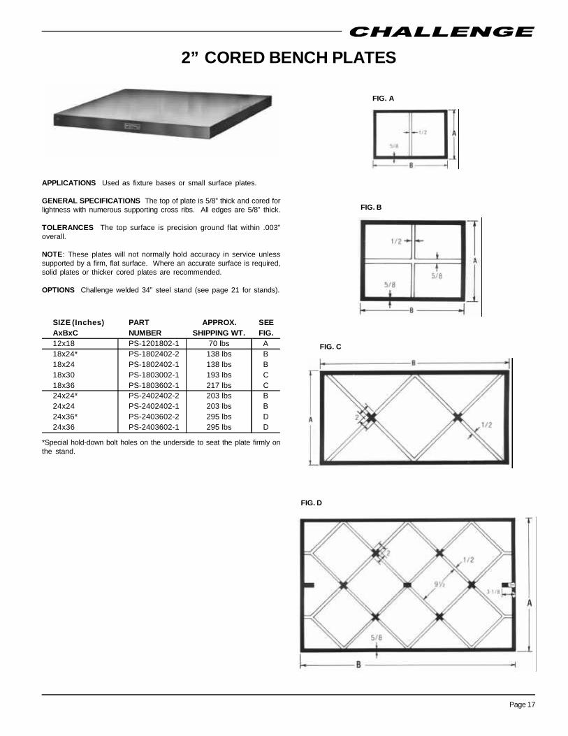
2” CORED BENCH PLATES
APPLICATIONS Used as fixture bases or small surface plates.
GENERAL SPECIFICATIONS The top of plate is 5/8” thick and cored forlightness with numerous supporting cross ribs. All edges are 5/8” thick.
TOLERANCES The top surface is precision ground flat within .003”overall.
NOTE: These plates will not normally hold accuracy in service unlesssupported by a firm, flat surface. Where an accurate surface is required,solid plates or thicker cored plates are recommended.
OPTIONS Challenge welded 34” steel stand (see page 21 for stands).
FIG. A
FIG. B
FIG. C
FIG. D
SIZE (Inches) PART APPROX. SEEAxBxC NUMBER SHIPPING WT. FIG.12x18 PS-1201802-1 70 lbs A18x24* PS-1802402-2 138 lbs B18x24 PS-1802402-1 138 lbs B18x30 PS-1803002-1 193 lbs C18x36 PS-1803602-1 217 lbs C24x24* PS-2402402-2 203 lbs B24x24 PS-2402402-1 203 lbs B24x36* PS-2403602-2 295 lbs D24x36 PS-2403602-1 295 lbs D
*Special hold-down bolt holes on the underside to seat the plate firmly onthe stand.

Page 18
4” CORED BENCH PLATES
APPLICATIONS Used for precision layout and inspection, as fixturebases and set-up plates.
GENERAL SPECIFICATIONS They are cored for lightness with a solidtop 7/8” thick. Numerous cross supporting ribs are 3/4” thick. Outsidewalls are 7/8” thick. Sides are machined square with the top surface.
TOLERANCES - Precision ground: Flat within .001”.
TOLERANCES - *Machine finish: Flat within .002”.
NOTE: To maintain accuracy in service, plates should be supported by afirm, flat surface such as a surface plate or machine bed or supported bya Challenge layout plate stand and leveled properly.
OPTIONS 30x48 to 36x72 can be precision ground.Challenge welded 32” steel stand (see page 21 for stands).
DIMENSIONS
FIG. A FIG. B
FIG. C
FIG. D
FIG. E
FIG. F
SIZE (Inches) PART APPROX. SEEAxBxC NUMBER SHIPPING WT. FIG.12x18x4 PS-1201804-1 140 lbs A18x24x4 PS-1802404-1 238 lbs A18x30x4 PS-1803004-1 316 lbs B24x36x4 PS-2403604-1 473 lbs B24x60x4 PS-2406004-1 729 lbs D*30x48x4 PS-3004804 708 lbs C*30x60x4 PS-3006004 918 lbs C*36x48x4 PS-3604804 852 lbs E*36x60x4 PS-3606004 1181 lbs F*36x72x4 PS-3607204 1312 lbs F*48x48x4 PS-4804804 1151 lbs E*48x60x4 PS-4806004 1527 lbs E
SEE EDGE RIB EDGE RIB
SIZE F IG. TO RIB TO RIB TO RIB TO RIB LNGTH WIDTH
AxB D E F G H J18x24 A 9.00 - 12.00 - 10.75 7.7518x30 B 9.00 - 10.17 9.66 8.92 7.7524x36 B 12.00 - 12.17 11.66 10.92 10.7524x60 D 12.00 - 12.30 11.80 11.05 10.75*30x48 C 15.00 - 12.25 11.75 11.00 13.75*30x60 C 15.00 - 15.25 14.75 14.00 13.75*36x48 E 9.25 8.75 12.25 11.75 11.00 8.00*36x60 F 9.25 8.75 12.30 11.80 11.05 8.00*36x72 F 9.25 8.75 14.70 14.20 13.45 8.00*48x48 E 12.25 11.75 12.25 11.75 11.00 11.00*48x60 E 12.25 11.75 15.25 14.75 14.00 11.00*48x72 F 12.25 11.75 14.70 14.20 13.45 11.00
RIB LOCATION
POCKET SIZE
WIDTH LENGTH
Page 19
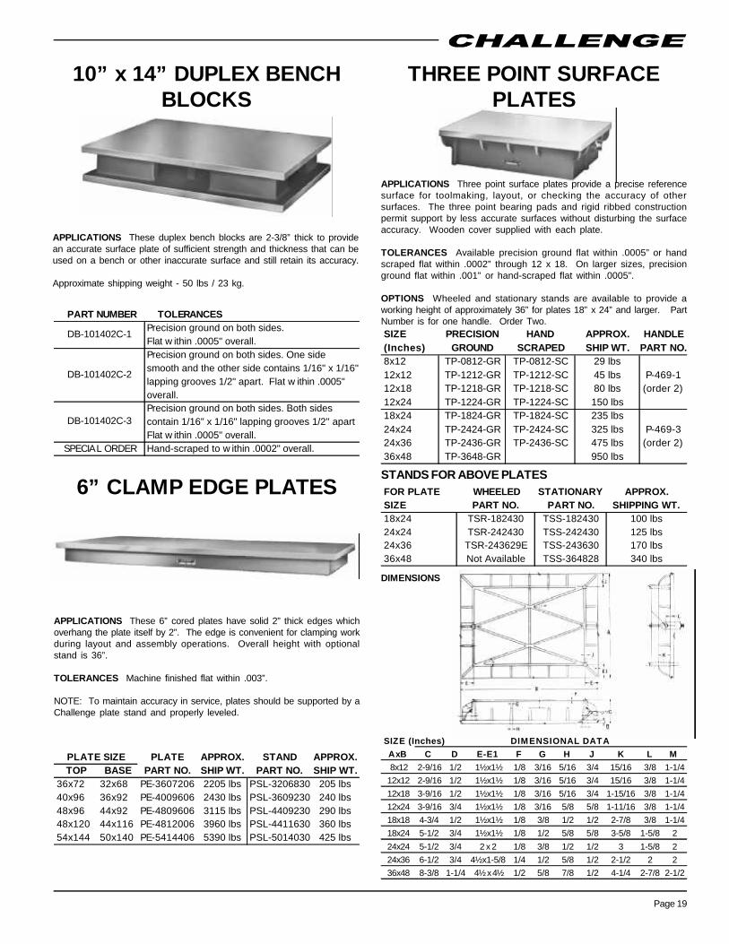
10” x 14” DUPLEX BENCHBLOCKS
THREE POINT SURFACEPLATES
6” CLAMP EDGE PLATES
APPLICATIONS These duplex bench blocks are 2-3/8” thick to providean accurate surface plate of sufficient strength and thickness that can beused on a bench or other inaccurate surface and still retain its accuracy.
Approximate shipping weight - 50 lbs / 23 kg.
APPLICATIONS These 6” cored plates have solid 2” thick edges whichoverhang the plate itself by 2”. The edge is convenient for clamping workduring layout and assembly operations. Overall height with optionalstand is 36”.
TOLERANCES Machine finished flat within .003”.
NOTE: To maintain accuracy in service, plates should be supported by aChallenge plate stand and properly leveled.
APPLICATIONS Three point surface plates provide a precise referencesurface for toolmaking, layout, or checking the accuracy of othersurfaces. The three point bearing pads and rigid ribbed constructionpermit support by less accurate surfaces without disturbing the surfaceaccuracy. Wooden cover supplied with each plate.
TOLERANCES Available precision ground flat within .0005” or handscraped flat within .0002” through 12 x 18. On larger sizes, precisionground flat within .001” or hand-scraped flat within .0005”.
OPTIONS Wheeled and stationary stands are available to provide aworking height of approximately 36” for plates 18” x 24” and larger. PartNumber is for one handle. Order Two.
STANDS FOR ABOVE PLATES
DIMENSIONS
PLATE APPROX. STAND APPROX.TOP BASE PART NO. SHIP WT. PART NO. SHIP WT.
36x72 32x68 PE-3607206 2205 lbs PSL-3206830 205 lbs40x96 36x92 PE-4009606 2430 lbs PSL-3609230 240 lbs48x96 44x92 PE-4809606 3115 lbs PSL-4409230 290 lbs48x120 44x116 PE-4812006 3960 lbs PSL-4411630 360 lbs54x144 50x140 PE-5414406 5390 lbs PSL-5014030 425 lbs
PLATE SIZE
FOR PLATE WHEELED STATIONARY APPROX.SIZE PART NO. PART NO. SHIPPING WT.18x24 TSR-182430 TSS-182430 100 lbs24x24 TSR-242430 TSS-242430 125 lbs24x36 TSR-243629E TSS-243630 170 lbs36x48 Not Available TSS-364828 340 lbs
SIZE (Inches) DIMENSIONAL DATAAxB C D E-E1 F G H J K L M8x12 2-9/16 1/2 1½ x1½ 1/8 3/16 5/16 3/4 15/16 3/8 1-1/4
12x12 2-9/16 1/2 1½ x1½ 1/8 3/16 5/16 3/4 15/16 3/8 1-1/412x18 3-9/16 1/2 1½ x1½ 1/8 3/16 5/16 3/4 1-15/16 3/8 1-1/412x24 3-9/16 3/4 1½ x1½ 1/8 3/16 5/8 5/8 1-11/16 3/8 1-1/418x18 4-3/4 1/2 1½ x1½ 1/8 3/8 1/2 1/2 2-7/8 3/8 1-1/418x24 5-1/2 3/4 1½ x1½ 1/8 1/2 5/8 5/8 3-5/8 1-5/8 224x24 5-1/2 3/4 2 x 2 1/8 3/8 1/2 1/2 3 1-5/8 224x36 6-1/2 3/4 4½ x1-5/8 1/4 1/2 5/8 1/2 2-1/2 2 236x48 8-3/8 1-1/4 4½ x 4½ 1/2 5/8 7/8 1/2 4-1/4 2-7/8 2-1/2
PART NUMBER TOLERANCESPrecision ground on both sides.Flat w ithin .0005" overall.Precision ground on both sides. One sidesmooth and the other side contains 1/16" x 1/16''lapping grooves 1/2" apart. Flat w ithin .0005''overall.Precision ground on both sides. Both sidescontain 1/16" x 1/16" lapping grooves 1/2'' apartFlat w ithin .0005" overall.
SPECIAL ORDER Hand-scraped to w ithin .0002" overall.
DB-101402C-1
DB-101402C-2
DB-101402C-3
SIZE PRECISION HAND APPROX. HANDLE(Inches) GROUND SCRAPED SHIP WT. PART NO.8x12 TP-0812-GR TP-0812-SC 29 lbs12x12 TP-1212-GR TP-1212-SC 45 lbs P-469-112x18 TP-1218-GR TP-1218-SC 80 lbs (order 2)12x24 TP-1224-GR TP-1224-SC 150 lbs18x24 TP-1824-GR TP-1824-SC 235 lbs24x24 TP-2424-GR TP-2424-SC 325 lbs P-469-324x36 TP-2436-GR TP-2436-SC 475 lbs (order 2)36x48 TP-3648-GR 950 lbs

Page 20
STANDARD 6” LAYOUT PLATES
APPLICATIONS These plates can be used for a wide variety ofapplications including precision layout and assembly, checking tables,large fixture or machine bases, set-up plates, laboratory test plates, orstable surfaces for optical systems.
They have 1” thick tops and are heavily ribbed for good surface rigidityunder heavy loads. They are cored for lightness and the sides and endsare machined square to the top surface. They can be used individually orcombined for nearly any size.
OPTIONS
• T-slots - normally located at 12” on center accross the length andwidth of plate starting 6” from the edges. A 5/8” T-slot is standard witha 2” top.
• Entry holes and drain troughs.
• Mounting and positioning holes.
• Keyways or scribe lines.
• Heavy-duty welded steel stands.
• Installation and calibration services.
S T A N D A R D P L A T E S T - S L O T T E D P L A T ESM A C HINE FINISHED M A C HINE FINISHED
SIZE ( Inche s ) P A RT NUM BER P A RT NUM B ER3 0 x 6 0 PS-3006006 PS-3006006-2 1014 lbs 1428 lbs3 6 x 4 8 PS-3604806 PS-3604806-2 974 lbs 1371 lbs3 6 x 6 0 PS-3606006 PS-3606006-2 1217 lbs 1714 lbs3 6 x 7 2 PS-3607206 PS-3607206-2 1461 lbs 2057 lbs3 6 x 8 4 PS-3608406 PS-3608406-2 1704 lbs 2400 lbs3 6 x 9 6 PS-3609606 PS-3609606-2 1947 lbs 2742 lbs4 8 x 6 0 PS-4806006 PS-4806006-2 1623 lbs 2285 lbs4 8 x 7 2 PS-4807206 PS-4807206-2 1947 lbs 2742 lbs4 8 x 8 4 PS-4808406 PS-4808406-2 2272 lbs 3199 lbs4 8 x 9 6 PS-4809606 PS-4809606-2 2596 lbs 3656 lbs4 8 x 1 2 0 PS-4812006 PS-4812006-2 3245 lbs 4570 lbs6 0 x 7 2 PS-6007206 PS-6007206-2 2434 lbs 3428 lbs6 0 x 8 4 PS-6008406 PS-6008406-2 2840 lbs 4000 lbs6 0 x 9 6 PS-6009606 PS-6009606-2 3245 lbs 4570 lbs6 0 x 1 0 8 PS-6010806 PS-6010806-2 3652 lbs 5142 lbs6 0 x 1 2 0 PS-6012006 PS-6012006-2 4057 lbs 5713 lbs7 2 x 8 4 PS-7208406 PS-7208406-2 3408 lbs 4799 lbs7 2 x 9 6 PS-7209606 PS-7209606-2 3894 lbs 5484 lbs7 2 x 1 0 8 PS-7210806 PS-7210806-2 4382 lbs 6170 lbs7 2 x 1 2 0 PS-7212006 PS-7212006-2 4868 lbs 6855 lbs7 2 x 1 3 2 PS-7213206 PS-7213206-2 5355 lbs 7541 lbs7 2 x 1 4 4 PS-7214406 PS-7214406-2 5841 lbs 8226 lbs
A P P ROXIM A T E S H I P P I N G W EIGHT
S T A N D A R D T - S L O T T ED

Page 21
LAYOUT PLATE STANDS
GENERAL SPECIFICATIONS Challenge welded all-steel stands arespecially designed to provide rigid support for Challenge plates. Theyare equipped with adjusting screws at key points so the plates can beproperly leveled or releveled as needed.
Unless otherwise specified, stands are constructed to provide a workingheight of 36” at the plate surface. Example: For a 6” plate, the standsare 30” high; for a 4” plate they are 32”; and for a 2” plate they are 34”.
Corner detail ofhold-down &leveling screws on2” plates.
Corner detail ofleveling screws on4” and 6” plates.
PLATE APPROX.SIZE (Inches) 6" PLATE 4" PLATE 2" PLATE SHIPPING WT.
18x24 -N/A - PSL-1802432 PSL-1802434 100 lbs24x24 -N/A - -N/A - PSL-2402434 120 lbs24x36 -N/A - PSL-2403632 PSL-2403634 130 lbs24x60 -N/A - PSL-2406032 -N/A - 150 lbs30x48 -N/A - PSL-3004832 -N/A - 180 lbs30x60 PSL-3006030 PSL-3006032 -N/A - 200 lbs36x48 PSL-3604830 PSL-3604832 -N/A - 200 lbs36x60 PSL-3606030 PSL-3606032 -N/A - 210 lbs36x72 PSL-3607230 PSL-3607232 -N/A - 225 lbs36x84 PSL-3608430 -N/A - -N/A - 235 lbs36x96 PSL-3609630 -N/A - -N/A - 245 lbs48x48 PSL-4804830 PSL-4804832 -N/A - 220 lbs48x60 PSL-4806030 PSL-4806032 -N/A - 230 lbs48x72 PSL-4807230 PSL-4807232 -N/A - 245 lbs48x84 PSL-4808430 -N/A - -N/A - 285 lbs48x96 PSL-4809630 -N/A - -N/A - 315 lbs60x72 PSL-6007230 -N/A - -N/A - 310 lbs60x84 PSL-6008430 -N/A - -N/A - 355 lbs60x96 PSL-6009630 -N/A - -N/A - 370 lbs60x108 PSL-6010830 -N/A - -N/A - 390 lbs60x120 PSL-6012030 -N/A - -N/A - 435 lbs72x84 PSL-7208430 -N/A - -N/A - 400 lbs72x96 PSL-7209630 -N/A - -N/A - 440 lbs72x108 PSL-7210830 -N/A - -N/A - 480 lbs72x120 PSL-7212030 -N/A - -N/A - 520 lbs72x132 PSL-7213230 -N/A - -N/A - 560 lbs72x144 PSL-7214430 -N/A - -N/A - 600 lbs
STAND PART NUMBERS BY PLATE THICKNESS

Page 22
6” FLOOR PLATES
APPLICATIONS These plates are available in a wide rangeof sizes up to 120” wide and 336” long in a one-piecedesign. Unlimited size when used in combination. Otherthicknesses can also be provided on special order. Theyprovide the most accurate type of semi-steel base whenmounted on a solid concrete foundation of suitablethickness. Specially designed leveling devices are suppliedwith the plates, accessible from the top of the plate.Recessing the plate to floor level allows easier on- and-offmovement of heavy loads. The pit depth is equal to plusone- (1) inch of the thickness of the plate.
OPTIONS T-slots (5/8”) normally located at 12” on centeracross the length and width of the plate, starting at 6” fromthe edges. Also available: Grouting and air bleed holes,entry holes, drain troughs, positioning holes, keyways,scribe lines, and installation and calibration services.
TOLERANCES Machine finished flat within .002” T.I.R.overall.
When used in combination, tolerance is .005”.
NOTE: If plates are to match in thickness, they must beordered together. Otherwise, exact thickness of plateshould be specified when ordering.
S T A N D A R D T - S L O T T E DS I Z E ( I n c h e s ) P A R T N U M B E R P A R T N U M B E R S T A N D A R D T - S L O T T E D
3 0 x 6 0 P F - 3 0 0 6 0 0 6 P F - 3 0 0 6 0 0 6 - 2 1 0 1 4 lb s 1 4 2 8 lb s3 6 x 4 8 P F - 3 6 0 4 8 0 6 P F - 3 6 0 4 8 0 6 - 2 9 7 4 lb s 1 3 7 1 lb s3 6 x 6 0 P F - 3 6 0 6 0 0 6 P F - 3 6 0 6 0 0 6 - 2 1 2 1 7 lb s 1 7 1 4 lb s3 6 x 7 2 P F - 3 6 0 7 2 0 6 P F - 3 6 0 7 2 0 6 - 2 1 4 6 1 lb s 2 0 5 7 lb s3 6 x 8 4 P F - 3 6 0 8 4 0 6 P F - 3 6 0 8 4 0 6 - 2 1 7 0 4 lb s 2 4 0 0 lb s3 6 x 9 6 P F - 3 6 0 9 6 0 6 P F - 3 6 0 9 6 0 6 - 2 1 9 4 7 lb s 2 7 4 2 lb s4 8 x 6 0 P F - 4 8 0 6 0 0 6 P F - 4 8 0 6 0 0 6 - 2 1 6 2 3 lb s 2 2 8 5 lb s4 8 x 7 2 P F - 4 8 0 7 2 0 6 P F - 4 8 0 7 2 0 6 - 2 1 9 4 7 lb s 2 7 4 2 lb s4 8 x 8 4 P F - 4 8 0 8 4 0 6 P F - 4 8 0 8 4 0 6 - 2 2 2 7 2 lb s 3 1 9 9 lb s4 8 x 9 6 P F - 4 8 0 9 6 0 6 P F - 4 8 0 9 6 0 6 - 2 2 5 9 6 lb s 3 6 5 6 lb s4 8 x 1 2 0 P F - 4 8 1 2 0 0 6 P F - 4 8 1 2 0 0 6 - 2 3 2 4 5 lb s 4 5 7 0 lb s6 0 x 7 2 P F - 6 0 0 7 2 0 6 P F - 6 0 0 7 2 0 6 - 2 2 4 3 4 lb s 3 4 2 8 lb s6 0 x 8 4 P F - 6 0 0 8 4 0 6 P F - 6 0 0 8 4 0 6 - 2 2 8 4 0 lb s 4 0 0 0 lb s6 0 x 9 6 P F - 6 0 0 9 6 0 6 P F - 6 0 0 9 6 0 6 - 2 3 2 4 5 lb s 4 5 7 0 lb s6 0 x 1 0 8 P F - 6 0 1 0 8 0 6 P F - 6 0 1 0 8 0 6 - 2 3 6 5 2 lb s 5 1 4 2 lb s6 0 x 1 2 0 P F - 6 0 1 2 0 0 6 P F - 6 0 1 2 0 0 6 - 2 4 0 5 7 lb s 5 7 1 3 lb s7 2 x 8 4 P F - 7 2 0 8 4 0 6 P F - 7 2 0 8 4 0 6 - 2 3 4 0 8 lb s 4 7 9 9 lb s7 2 x 9 6 P F - 7 2 0 9 6 0 6 P F - 7 2 0 9 6 0 6 - 2 3 8 9 4 lb s 5 4 8 4 lb s7 2 x 1 0 8 P F - 7 2 1 0 8 0 6 P F - 7 2 1 0 8 0 6 - 2 4 3 8 2 lb s 6 1 7 0 lb s7 2 x 1 2 0 P F - 7 2 1 2 0 0 6 P F - 7 2 1 2 0 0 6 - 2 4 8 6 8 lb s 6 8 5 5 lb s7 2 x 1 3 2 P F - 7 2 1 3 2 0 6 P F - 7 2 1 3 2 0 6 - 2 5 3 5 5 lb s 7 5 4 1 lb s7 2 x 1 4 4 P F - 7 2 1 4 4 0 6 P F - 7 2 1 4 4 0 6 - 2 5 8 4 1 lb s 8 2 2 6 lb s
A P P R O X I M A T E S H I P P I N G W E I G H T

Page 23
STEEL WELDMENTS
APPLICATIONS Especially designed for boring mills to bring the workpiece up to working height. The weldments are heavily ribbed to preventtable sag. A base flange is provided at the bottom for use in mounting ona foundation, floor plate, or machine base.
Made of steel weldments. All sides and bottom are machine finished toprovide smooth mating surfaces to a floor plate, machine base, or for usein multiple sections.
NOTE No part numbers are listed since weldments are custom made toyour specifications. The picture above is only a sample design. Differentdesigns are available.
OPTIONS T-slots and drilled & tapped holes.
50” x 70” MACHINE LAYOUTPLATE
PART NO. PL-5007006
APPLICATIONS These machine plates will match up with your presentPortage brand plates for use in combination set-ups. They can also beused individually.
GENERAL SPECIFICATIONS They are 6” thick with 1” thick solid topsand heavily ribbed construction underneath for good surface rigidityunder heavy loads.
The sides and ends are machined square with the top so they can becombined accurately to provide surfaces of almost any size.
Dowel pin stops are installed at the end of each slot.
GUIDING SLOTS The guiding slots on which machines or measuringdevices move are in a grid starting at 5” from the edges and 10” apart inboth directions to provide accurate movement of the measuring heads inany position.
TOLERANCES Machine finished flat within .002”. Slot center to centeris ±.001”. Tolerance is noncumulative between slots to ensurecontinuous movement of N/C measuring equipment when two or moretables are combined.
When used in combination with each other, tolerances are .005”
OPTIONS Grid patterns, scribe lines, drilled and tapped holes, andinstallation and calibration services.
APPROX. SHIPPING WEIGHT 2300 lbs / 1044 kg
PLATE STAND FOR ABOVE PLATEPART NO. PLS-2604625-1
These heavy-duty stands have leveling screws on all four legs so platescan be accurately leveled. They are 24” high with 1” required foradjustment devices, which provides a working height of 31”.
Leveling can be done through holes in the table surface.
W I D T H - A L E N G T H - B H E I G H T - C2 4 3 6 1 83 6 4 8 2 44 8 6 0 3 06 0 7 2 3 67 2 9 6
1 2 01 4 41 6 81 9 22 1 62 4 02 6 42 8 8
S A M P L E C O M B I N A T IO N S ( In c h e s )

Page 24
Challenge Granite Surface Plates offer very accurate, stable, precisionsurfaces that can be used for layout, gauging, and inspection. These platesalso can be used as bases for fixtures, coordinate measuring machines,and other machines. They are self-supporting, have a low co-efficient ofexpansion, and a low degree of surface deflection under normal loads. Oursurface plates meet or exceed Federal Specification GGG-P-463c and arein compliance with MIL-STD-45662A. Final inspection and calibration of everysurface plate is accomplished by use of an Auto-Collimator. A certificate ofaccuracy, traceable to the National Institute of Standards and Technology, isfurnished with all surface plates. All plates have a thickness capable ofsupporting a total normal load equal to 100 pounds for each square foot ofsurface plate area loaded in the center of the plate without defelecting theplate along a diagonal line more than one-half the flatness tolerance. CharcoalBlack granite is standard except for plates larger than 48” x 72” which areSierra Grey. Pink Granite is available as an option in most sizes.
S iz e ( i n c h )
T h ic k -n e s s ( in c h )
G r a d e N o L e d g e P a r t N u m b e r
2 L e d g e P a r t N u m b e r
4 L e d g e P a r t N u m b e r
O v e r a ll U n ila t e r a l A c c u r a c y
A p p r o x . S h ip
W e ig h t ( lb s )
3 A A G A A - 0 8 1 2 - 0 G A A - 0 8 1 2 - 2 G A A - 0 8 1 2 - 4 0 . 0 0 0 0 4 5 5 02 A G A - 0 8 1 2 - 0 G A - 0 8 1 2 - 2 G A - 0 8 1 2 - 4 0 . 0 0 0 9 4 02 B G B - 0 8 1 2 - 0 G B - 0 8 1 2 - 2 G B - 0 8 1 2 - 4 0 . 0 0 0 1 8 4 04 A A G A A - 1 2 1 2 - 0 G A A - 1 2 1 2 - 2 G A A - 1 2 1 2 - 4 0 . 0 0 0 0 5 6 04 A G A - 1 2 1 2 - 0 G A - 1 2 1 2 - 2 G A - 1 2 1 2 - 4 0 . 0 0 0 1 6 03 B G B - 1 2 1 2 - 0 G B - 1 2 1 2 - 2 G B - 1 2 1 2 - 4 0 . 0 0 0 2 5 04 A A G A A - 1 2 1 8 - 0 G A A - 1 2 1 8 - 2 G A A - 1 2 1 8 - 4 0 . 0 0 0 0 5 9 04 A G A - 1 2 1 8 - 0 G A - 1 2 1 8 - 2 G A - 1 2 1 8 - 4 0 . 0 0 0 1 9 03 B G B - 1 2 1 8 - 0 G B - 1 2 1 8 - 2 G B - 1 2 1 8 - 4 0 . 0 0 0 2 7 04 A A G A A - 1 8 1 8 - 0 G A A - 1 8 1 8 - 2 G A A - 1 8 1 8 - 4 0 . 0 0 0 0 6 1 3 54 A G A - 1 8 1 8 - 0 G A - 1 8 1 8 - 2 G A - 1 8 1 8 - 4 0 . 0 0 0 1 2 1 3 53 B G B - 1 8 1 8 - 0 G B - 1 8 1 8 - 2 G B - 1 8 1 8 - 4 0 . 0 0 0 2 4 1 0 04 A A G A A - 1 8 2 4 - 0 G A A - 1 8 2 4 - 2 G A A - 1 8 2 4 - 4 0 . 0 0 0 0 6 5 1 7 54 A G A - 1 8 2 4 - 0 G A - 1 8 2 4 - 2 G A - 1 8 2 4 - 4 0 . 0 0 0 1 3 1 7 53 B G B - 1 8 2 4 - 0 G B - 1 8 2 4 - 2 G B - 1 8 2 4 - 4 0 . 0 0 0 2 6 1 3 06 A A G A A - 2 4 2 4 - 0 G A A - 2 4 2 4 - 2 G A A - 2 4 2 4 - 4 0 . 0 0 0 0 7 2 7 54 A G A - 2 4 2 4 - 0 G A - 2 4 2 4 - 2 G A - 2 4 2 4 - 4 0 . 0 0 0 1 4 2 3 04 B G B - 2 4 2 4 - 0 G B - 2 4 2 4 - 2 G B - 2 4 2 4 - 4 0 . 0 0 0 2 8 2 3 06 A A G A A - 2 4 3 6 - 0 G A A - 2 4 3 6 - 2 G A A - 2 4 3 6 - 4 0 . 0 0 0 0 8 5 5 2 06 A G A - 2 4 3 6 - 0 G A - 2 4 3 6 - 2 G A - 2 4 3 6 - 4 0 . 0 0 0 1 7 5 2 04 B G B - 2 4 3 6 - 0 G B - 2 4 3 6 - 2 G B - 2 4 3 6 - 4 0 . 0 0 0 3 4 3 4 08 A A G A A - 2 4 4 8 - 0 G A A - 2 4 4 8 - 2 G A A - 2 4 4 8 - 4 0 . 0 0 0 1 5 9 2 56 A G A - 2 4 4 8 - 0 G A - 2 4 4 8 - 2 G A - 2 4 4 8 - 4 0 . 0 0 0 3 6 9 06 B G B - 2 4 4 8 - 0 G B - 2 4 4 8 - 2 G B - 2 4 4 8 - 4 0 . 0 0 0 6 6 9 06 A A G A A - 3 0 3 6 - 0 G A A - 3 0 3 6 - 2 G A A - 3 0 3 6 - 4 0 . 0 0 0 1 6 7 56 A G A - 3 0 3 6 - 0 G A - 3 0 3 6 - 2 G A - 3 0 3 6 - 4 0 . 0 0 0 2 6 7 56 B G B - 3 0 3 6 - 0 G B - 3 0 3 6 - 2 G B - 3 0 3 6 - 4 0 . 0 0 0 4 6 7 56 A A G A A - 3 6 3 6 - 0 G A A - 3 6 3 6 - 2 G A A - 3 6 3 6 - 4 0 . 0 0 0 1 7 8 06 A G A - 3 6 3 6 - 0 G A - 3 6 3 6 - 2 G A - 3 6 3 6 - 4 0 . 0 0 0 2 7 8 05 B G B - 3 6 3 6 - 0 G B - 3 6 3 6 - 2 G B - 3 6 3 6 - 4 0 . 0 0 0 4 6 5 08 A A G A A - 3 6 4 8 - 0 G A A - 3 6 4 8 - 2 G A A - 3 6 4 8 - 4 0 . 0 0 0 1 5 1 , 3 6 06 A G A - 3 6 4 8 - 0 G A - 3 6 4 8 - 2 G A - 3 6 4 8 - 4 0 . 0 0 0 3 1 , 1 0 06 B G B - 3 6 4 8 - 0 G B - 3 6 4 8 - 2 G B - 3 6 4 8 - 4 0 . 0 0 0 6 1 , 1 0 0
1 0 A A G A A - 3 6 6 0 - 0 G A A - 3 6 6 0 - 2 G A A - 3 6 6 0 - 4 0 . 0 0 0 2 2 , 1 2 58 A G A - 3 6 6 0 - 0 G A - 3 6 6 0 - 2 G A - 3 6 6 0 - 4 0 . 0 0 0 4 1 , 7 0 06 B G B - 3 6 6 0 - 0 G B - 3 6 6 0 - 2 G B - 3 6 6 0 - 4 0 . 0 0 0 8 1 , 2 7 5
1 2 A A G A A - 3 6 7 2 - 0 G A A - 3 6 7 2 - 2 G A A - 3 6 7 2 - 4 0 . 0 0 0 2 5 3 , 0 6 01 0 A G A - 3 6 7 2 - 0 G A - 3 6 7 2 - 2 G A - 3 6 7 2 - 4 0 . 0 0 0 5 2 , 5 5 08 B G B - 3 6 7 2 - 0 G B - 3 6 7 2 - 2 G B - 3 6 7 2 - 4 0 . 0 0 1 2 , 0 4 0
1 0 A A G A A - 4 8 6 0 - 0 G A A - 4 8 6 0 - 2 G A A - 4 8 6 0 - 4 0 . 0 0 0 2 5 2 , 8 5 08 A G A - 4 8 6 0 - 0 G A - 4 8 6 0 - 2 G A - 4 8 6 0 - 4 0 . 0 0 0 5 2 , 3 0 06 B G B - 4 8 6 0 - 0 G B - 4 8 6 0 - 2 G B - 4 8 6 0 - 4 0 . 0 0 1 1 , 7 0 0
1 2 A A G A A - 4 8 7 2 - 0 G A A - 4 8 7 2 - 2 G A A - 4 8 7 2 - 4 0 . 0 0 0 3 4 , 0 8 01 0 A G A - 4 8 7 2 - 0 G A - 4 8 7 2 - 2 G A - 4 8 7 2 - 4 0 . 0 0 0 6 3 , 4 0 08 B G B - 4 8 7 2 - 0 G B - 4 8 7 2 - 2 G B - 4 8 7 2 - 4 0 . 0 0 1 2 2 , 7 2 0
1 4 A A G A A - 4 8 9 6 - 0 G A A - 4 8 9 6 - 2 G A A - 4 8 9 6 - 4 0 . 0 0 0 4 6 , 3 5 01 2 A G A - 4 8 9 6 - 0 G A - 4 8 9 6 - 2 G A - 4 8 9 6 - 4 0 . 0 0 0 8 5 , 4 4 01 0 B G B - 4 8 9 6 - 0 G B - 4 8 9 6 - 2 G B - 4 8 9 6 - 4 0 . 0 0 1 6 4 , 5 4 0
3 6 x 7 2
4 8 x 6 0
4 8 x 7 2
4 8 x 9 6
3 0 x 3 6
3 6 x 3 6
3 6 x 4 8
3 6 x 6 0
1 8 x 2 4
2 4 x 2 4
2 4 x 3 6
2 4 x 4 8
8 x 1 2
1 2 x 1 2
1 2 x 1 8
1 8 x 1 8

Page 25
These heavy-duty steel stands are available for all granite plates.Stationary stands have leveling screws at the bottom of each leg.Castered stands are funished with two fixed and two swivel casters foreasy movement. The stands have a three-point support design and aremde according to plate thickness and number of ledges. WHEN PLACINGYOUR ORDER PLEASE SPECIFY NUMBER OF LEDGES ON THE GRANITEPLATE AND PLATE THICKNESS. The overall working height of the plateand stand will be approximately 36” (900mm).
Cabinet Stands are constructed using square steel tubing and heavygauge steel. Leveling screws are provided on the bottom of each leg .The standard working height is 36” (900mm). Roomy cabinet space isprovided with a shelf and locking doors. Casters and a floorlock can beprovided at an additional charge.
12 x 18 GSS-1218 GRS-1218 4518 x 24 GSS-1824 GRS-1824 7524 x 24 GSS-2424 GRS-2424 85
24 x 36 GSC-2436 GRC-2436 9524 x 48 GSC-2448 GRC-2448 14530 x 36 GSC-3036 GRC-3036 15536 x 36 GSC-3636 GRC-3636 16536 x 48 GSC-3648 GRC-3648 18536 x 60 GSC-3660 GRC-3660 20536 x 72 GSC-3672 GRC-3672 23548 x 60 GSC-4860 GRC-4860 25548 x 72 GSC-4872 GRC-4872 26548 x 96 GSC-4896 GRC-4896 345
SizeStationary
Part NumberCasters
Part NumberApprox. Ship Weight (lbs)
Drawer Stands are manufactured with the same high quality as ourother stands but now provide the convenience of sliding drawers. Eachdrawer can hold up to 400 lbs. of equipment. In addition, each drawerextends fully to allow for total utilization of space.
24 x 36 GSD-2436 GRD-2436 25036 x 36 GSD-3636 GRD-3636 28036 x 48 GSD-3648 GRD-3648 330
SizeStationary
Part NumberCasters
Part NumberApprox. Ship Weight (lbs)
24" x 36" GSC-2436 GRC-2436 20036" x 48" GSC-3648 GRC-3648 32536" x 60" GSC-3660 GRC-3660 38036" x 72" GSC-3672 GRC-3672 45048" x 72" GSC-4872 GRC-4872 650
Approx. Ship Weight (lbs)
SizeStationary
Part NumberCasters
Part Number

Page 26
Furnished with two surfaces (base and face), or four surfaces (base, face, and two sides) finished.Finished square and flat to tolerances shown below. Cases are available.
Inspection Grade - .000050 per 6” Laboratory Grade .000025 per 6”
Part Number - 2 Faced
Part Number - 4 Faced
Part Number - 2 Faced
Part Number - 4 Faced
4 x 4 x 4 G A I-040404-I2 G A I-040404-I4 GA I-040404-L2 GA I-040404-L46 x 6 x 6 G A I-060606-I2 G A I-060606-I4 GA I-060606-L2 GA I-060606-L2
6 x 9 x 12 G A I-060912-I2 G A I-060912-I4 GA I-060912-L2 GA I-060912-L49 x 9 x 9 G A I-090909-I2 G A I-090909-I4 GA I-090909-L2 GA I-090909-L4
12 x 12 x 12 G A I-121212-I2 G A I-121212-I4 GA I-121212-L2 GA I-121212-L4
Inspect ion Grade Laboratory GradeSize (inch)
Inserted Angles have metal discs located in both one side, and main face for magnetizing purposes.Threaded inserts for clamping are located on the other main face. Tolerances are shown below.Cases are available.
Inspection Grade - .000050 per 6’’ Laboratory Grade - .000025” per 6”
Straight Edges are used for checking the flatness of machine ways or beds, surface plates, and manyother applications. Accuracies are measured on a center line of gauging surface per 12”. Tolerancesare shown below. Cases are available.
Inspection Grade - Laboratory Grade -.000050 per 12” .000025 per 12”
Parallels are matched in pairs and held parallel on top and bottom (two faces) or on top, bottom, andboth sides (four faces) to overall accuracy listed below. Dimensions are held to nominal size +/- 1/32”.Cases are available.
Inspection Grade - .000050 per 12” Laboratory Grade - .000025 per 12”
Part Number - 2 Faced
Part Number - 4 Faced
Part Number - 2 Faced
Part Number - 4 Faced
3/4 x 1 x 6 GEP-00H0106-I2 GEP-00H0106-I4 GEP-00H0106-L2 GEP-00H0106-L41 x 2 x 12 GEP-010212-I2 GEP-010212-I4 GEP-010212-L2 GEP-010212-L4
1 1/2 x 3 x 18 GEP-01E0318-I2 GEP-01E0318-I4 GEP-01E0318-L2 GEP-01E0318-L42 x 4 x 24 GEP-020424-I2 GEP-020424-I4 GEP-020424-L2 GEP-020424-L4
Inspection Grade Laboratory GradeSize (inch)
Part Number - 2 Faced
Part Number - 4 Faced
Part Number - 2 Faced
Part Number - 4 Faced
4 x 4 x 4 GA P-040404-I2 GA P-040404-I4 GAP-040404-L2 GAP-040404-L46 x 6 x 6 GA P-060606-I2 GA P-060606-I4 GAP-060606-L2 GAP-060606-L2
6 x 9 x 12 GA P-060912-I2 GA P-060912-I4 GAP-060912-L2 GAP-060912-L49 x 9 x 9 GA P-090909-I2 GA P-090909-I4 GAP-090909-L2 GAP-090909-L4
12 x 12 x 12 GA P-121212-I2 GA P-121212-I4 GAP-121212-L2 GAP-121212-L4
Inspection Grade Laboratory GradeSize (inch)
Size (inch)Inspection Grade
Part NumberLaboratory Grade
Part Number2 x 4 x 24 GES-024-I GES-024-L2 x 6 x 36 GES-036-I GES-036-L2 x 8 x 48 GES-048-I GES-048-L
3 x 10 x 60 GES-060-I GES-060-L3 x 12 x 72 GES-072-I GES-072-L

Page 27
V-Blocks are furnished in pairs. V-blocks have 90 degree V’s that are centered and parallelto bottom and two sides, square to the ends. Tolerances shown below. Cases are available.
Inspection Grade - Laboratory Grade -+/- .00005 per 6” +/- .000025 per 6”
S iz e ( in c h )In s p e c t io n G r a d e
P a r t N u m b e rL a b o r a t o r y G r a d e
P a r t N u m b e rA p p r o x . S h ip W e ig h t ( lb s )
3 x 3 x 3 G V S - 0 3 0 3 0 3 - IV 5 G V S - 0 3 0 3 0 3 - L V 5 54 x 4 x 4 G V S - 0 4 0 4 0 4 - IV 5 G V S - 0 4 0 4 0 4 - L V 5 1 26 x 6 x 6 G V S - 0 6 0 6 0 6 - IV 5 G V S - 0 6 0 6 0 6 - L V 5 4 09 x 9 x 9 G V S - 0 9 0 9 0 9 - IV 5 G V S - 0 9 0 9 0 9 - L V 5 9 5
1 2 x 1 2 x 1 2 G V S - 1 2 1 2 1 2 - IV 5 G V S - 1 2 1 2 1 2 - L V 5 1 5 5
Master Squares are finished with four narrow faces and one large face finished.Cases are available.
Inspection Grade - Laboratory Grade -.000050 per 6” .000025 per 6”
Size (inch)Inspection Grade
Part NumberLaboratory Grade
Part NumberA pprox. Ship Weight (lbs)
12 x 12 x 3 GMS-121203-I GMS-121203-L 4514 x 14 x 3 GMS-141403-I GMS-141403-L 6118 x 18 x 3 GMS-181803-I GMS-181803-L 10224 x 24 x 4 GMS-242404-I GMS-242404-L 24036 x 36 x 4 GMS-363604-I GMS-363604-L 810
Part Number - 2 Faced
Part Number - 3 Faced
Part Number - 2 Faced
Part Number - 3 Faced
6 x 9 x 3 GMA-060903-I2 GMA-060903-I4 GMA-060903-L2 GMA-060903-L4 139 x 18 x 3 GMA-091803-I2 GMA-091803-I4 GMA-091803-L2 GMA-091803-L4 38
12 x 18 x 3 GMA-121803-I2 GMA-121803-I4 GMA-121803-L2 GMA-121803-L4 6718 x 24 x 3 GMA-182403-I2 GMA-182403-I4 GMA-182403-L2 GMA-182403-L4 8824 x 36 x 6 GMA-243606-I2 GMA-243606-I4 GMA-243606-L2 GMA-243606-L4 450
Inspection Grade Laboratory Grade Approx. Ship Weight (lbs)
Size (inch)
Master Angles come furnished to the tolerances below. A two-faced Master Angle has the two narrowfaces finished. A three-faced Master Angle has the two narrow faces and one large face finished.Cases are available.
Inspection Grade - .00005 per 6” Laboratory Grade - .000025 per 6”
Cubes form a perpendicular, flat and parallel reference plane. Six faces are finished to the tolerancesbelow. The cube contains ten 1/4-20 stainless steel inserts that can be used for clamping. Matched pairsavailable upon request. Cases are available.
Inspection Grade - Laboratory Grade -.000050 per 6” .000025 per 6”
Size (inch)Inspection Grade
Part NumberLaboratory Grade
Part Number3 GCD-030303-I GCD-030303-L4 GCD-040404-I GCD-040404-L6 GCD-060606-I GCD-060606-L

? ?2002 Challenge Precision. All rights reserved.? Challenge is a registered trademark of Challenge PrecisionPrinted in the U.S.A.
5677 Airline Road - Fruitport, Michigan 49415 USAPhone: (231) 865-6944 - Fax: (231) 865-8887
1/02 CAT-02
www.challengeprecision.com