Embed Size (px)
Citation preview

Journal for Technology of Plasticity, Vol. 33 (2008), Number 1-2
PRECISION FORGING – TOOL CONCEPTS AND PROCESS DESIGN
Mladomir Milutinović, Dragiša Vilotić, Dejan Movrin
Faculty of technical sciences, Novi Sad, Serbia
ABSTRACT Contemporary forging industry is faced with different challenges and demands. It forced many forgers recently to make a review of traditional forging methods and to enter innovations in process and product design. Present day forging industry tends toward the replacement of conventional forging process (forging with flash) by precision forging. Precision forging enables manufacture of forgings with enhanced geometrical and dimensional accuracy, such as net-shape or near-net-shape components, in large quantities and with reasonable cost. Application of precision forging increases the competitive of this technology and offers many benefits to the product manufacturer - economical, technological and ecological. Crucial issues for successful application of precision forging are the process design, die design and die manufacturing. Compared to conventional forging process and tool design is more complex and more sensitive to potential errors. When design precision forging process, one have to take into account the great number of variables that have to fulfill some important aspects in order to realize the precision forging process on proper way. Therefore, a new approach in process planning as well as support of computers and engineering design tools are needed. In this paper, an outline of variables affecting the process of precision forging, requirements that they have to satisfy and critical aspects of the precision forging process are given. Basic tool concepts used in precision forging are also presented. Key words: Precision forging, Process variables, Tool concept 1. INTRODUCTION Forging is the oldest known metal processing technology which origins date far away to human past. During the forging process, a metal workpiece is plastically deformed to desired shape by application of compressive forces, at temperatures ranging from ambient to 1500ºC and more [19]. The products of forging may be tiny or massive, with simply and complex geometry and can be

74
Journal for Technology of Plasticity, Vol. 33 (2008), Number 1-2
made from any forgeable metal. Owing to good mechanical performances and high reliability, for a long time, forgings had reputation of irreplaceable components in applications where tension, dynamic load, demanding environments, human safety etc. are critical considerations. It provided forging prominent position among the various manufacturing technologies and there was no hard pressure to this industry for new and advanced products and processes. But, by time, the vacancy between performances of forged parts and parts produced by other ways slowly vanished. Permanent rise in the cost of energy and raw materials, demands for increasing accuracy of forged parts, pressure from global market, higher ecological demands etc. additionally influenced the position of forging industry. These things forced many forgers to make a review of their manufacturing methods so they can be cost and quality competitive. In recent years, one of the most important scope of research and development of modern forging technology is precision or flashless forging. Precision forging is used for the manufacture of high accuracy and complex forgings that can be classified as near-net shape or net shape parts requiring, therefore, zero or minimal machining. Precision forging can be performed through cold-warm-or hot forming process. For example, machining allowances of hot die-closed forged gears are range only 0.10mm per flank and clutch gearing have ready built in teeth surfaces [2] as the current minimum dimensional error in practical cold forging is ±20 o 50μm [22]. Development and application of precision forging led to high economical, technological and ecological improvements of forging process that brings many benefits to manufacturers. Studies have shown that, compared with shapes machined from plate, precision forgings can reduce part cost by 80 to 90 percent and decrease machining labor by as much as 95 percent. [24]. Compared with conventional closed die forgings, precision forgings can cut final part cost by 60 to 70 percent and reduce machining labor by up to 90 percent [24]. Dimensional accuracy of forged components which can be achieved through precision forging according to ISO IT standards are IT6-IT9 (conventional forging IT9-IT14) [1]. Typical appearance of conventional and precision forging part is given in Fig.1.
IT 12-14
IT 6-8
Figure 1 – Connected rod obtained by conventional and precision (flashless) forging [9]
Other advantages of flashless forging process are [24]:
1. The volume of the blank is reduced to the nominal volume of the finished product. This precipitates savings in material.
2. The dimensions of the forging may conform closely to the final dimensions of the product, no draft angles are needed. It results in reduction of subsequent machining and material costs.
75
Journal for Technology of Plasticity, Vol. 33 (2008), Number 1-2
3. Better corner filling can be accomplished due to the higher pressures associated with flashless forging.
4. The strength of a product after flashless forging is superior to that forged with a flash, since fibering flow lines in a flashless forging conform to the shape of the product, whereas in a forging with a flash they do not.
5. Usually flashless forging is performed in one forging step, from a blank of uniform cross section to a final shape through a single pair of dies, eliminating intermediate forging and (sometimes) annealing steps.
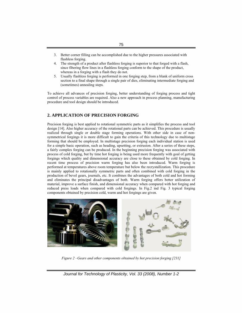
To achieve all advances of precision forging, better understanding of forging process and tight control of process variables are required. Also a new approach in process planning, manufacturing procedure and tool design should be introduced. 2. APPLICATION OF PRECISION FORGING Precision forging is best applied to rotational symmetric parts as it simplifies the process and tool design [14]. Also higher accuracy of the rotational parts can be achieved. This procedure is usually realized through single or double stage forming operations. With other side in case of non-symmetrical forgings it is more difficult to gain the criteria of this technology due to multistage forming that should be employed. In multistage precision forging each individual station is used for a simple basic operation, such as heading, upsetting, or extrusion. After a series of these steps, a fairly complex forging can be produced. In the beginning precision forging was associated with process of cold forging, but by time hot forging is being used more frequently with goal of getting forgings which quality and dimensional accuracy are close to these obtained by cold forging. In recent time process of precision warm forging has also been introduced. Warm forging is performed at temperatures above room temperature but below the recrystallization. This procedure is mainly applied to rotationally symmetric parts and often combined with cold forging in the production of bevel gears, journals, etc. It combines the advantages of both cold and hot forming and eliminates the principal disadvantages of both. Warm forging offers better utilization of material, improve a surface finish, and dimensional accuracy when compared with hot forging and reduced press loads when compared with cold forgings. In Fig.2 ind Fig. 3 typical forging components obtained by precision cold, warm and hot forgings are given.
Figure 2 –Gears and other components obtained by hot precision forging [231]

76
Journal for Technology of Plasticity, Vol. 33 (2008), Number 1-2
a)
b)
Figure 3 –Cold (a) and warm (b) precision forged components [23]
The choice of one process over another, for any product, depends on many factors, including the material of the workpiece, the size, quality, and quantity required etc. Some of the criteria for this choice are given by Sheljaskov [5], and summarized in Table 1. Table 1 - Comparison of forging process characteristics [5]
Criteria Hot Warm Cold
Weight of the Workpiece <60 kg <10 kg <2 kg
Steel Grade Any C desirable
Other alloying elements < 10 %
Low alloyed steels (C<0.45%, other
<3%)
Shape Any without undercut
Rotationally-symmetrical
without undercut
Rotationally-symmetrical
without undercut
Normally achievable surface quality R 100 μm 50 μm 10 μm
Intermediate Treatments Not necessary Normally no surface treatment
Annealing and phosphating
Deformation Pressure Low Medium High
Energy Costs High Medium Low
Tolerances Generous Close Closest
Tooling costs Lowest High High
Tool life (pieces) 5 000 – 10 000 10 000 -20 000 20 000 – 50 000

77
Journal for Technology of Plasticity, Vol. 33 (2008), Number 1-2
3. TOOLING FOR FLASHLESS FORGING In contrary to conventional closed die forging process which is realized by tooling comprises upper and lower die and where die-surface is designed with flash land to receive excess material, during precision forging process the billet is completely enclosed in the die cavity so that no flash formation is allowed (Fig. 4). To achieve the complete filling.
Figure 4 – Closed die forging with (a) and without flash (b) [3]
The tool set for precision forging generally consists of a lower and upper punch, one or more dies and a device to hold the dies closed during forming process. It requires multi-ram presses for punches to press the material as well as spring assemblies or separate closing devices to provide the necessary closing pressure during deformation. By controlling the motion of rams metal flow can be controlled to obtain the optimum deformation. The ram motions for upper and lower punches can be set as synchronous, asynchronous or with back pressure to reduce forming load to large extent or to improve the filling of material [4]. Some tool sets for precision forging comprise axially driven container which is separate from the die set (Fig. 5). It is considered that the friction between the billet-container interface helps to push the workpiece material into the corner of the die cavity. As result of this forming pressure is reduced and better accuracy of forging attained [6].
Figure 5 – Precision closed die forging with moving container [6]

78
Journal for Technology of Plasticity, Vol. 33 (2008), Number 1-2
For horizontally divided dies closing load can easily be provided by the ram movement combined with assemblies, while for vertically divided dies which are necessary for the ejection of parts with undercuts special devices for the transformation of vertical press loads into horizontal closing loads are used [2]. Fig. 6 shows double acting tool system for flashless forging of helical gear equipped with cup springs and columns to provide die movement and the necessary closing force. Modular system of this tool enables different gear wheels and other rotational symmetric parts up to weight of 1.5kg to be forged [2]. Better control of closing forces can be set up by using gas springs. Employing different gas pressures, the gas springs are able to be adjusted to different application cases. However, solutions with spring assemblies to provide closing force have a serious disadvantage – huge consumption of energy needed for forming process. Depending on the forging geometry and employed spring assembly up to 50% of the forging machine energy could be lost for closing of the dies [8]. This problem can be overcome by using different mechanisms such as pantograph mechanism. The tool set for flashless forging of bevel gears with this type of closing mechanism is developed by Nichadai Corp. [8] and given in Fig.7. Main disadvantage of this tool concept is its complexity.
Figure 6 – Double acting tool set for precision forging of helical gears [2]
In some cases energy of the elastic deformations of the die can be utilized for part forming. Such a tool is suggested by Ishida [8] and shown in Fig.8. When the core die (C) is pushed into the tapered outer die container (D), the core die shrinks elastically and forms the crowning shape on the gear teeth. When the core die is removed from the die container, it returns to the original shape, expanding away from the part and enables the crowned teeth to be removed easily from the die.

79
Journal for Technology of Plasticity, Vol. 33 (2008), Number 1-2
Figure 7 – Tool set for bevel gears with pantograph mechanism [8]
Figure 8 – Principle of precision forging of helical gears with crowned teeth using elastic
deformation of die [8]
Concepts of tools applied for single operations in multistage precision forging of flat long and non-symmetrical parts basically is the same the ones used in cases of rotational and axial-symmetrical forgings. However, their structure and geometry is usually more complex and modified according the multistage forming process. It is especially true for final forming tools. Flashless forging of connected rod is a typical represent of multistage precision forming process. There are different ways of developing forming sequences and perform shapes. A suitable forming procedure and tool concepts for multistage precision forging of connected rod developed at IPH [9] is shown in Fig. 9 and Fig. 10. Proposed solution for forming sequences comprises a few forming operations that are carried out by only two tool sets. Mass distribution and upsetting for intermediate part shaping are realized in a tooling (Fig.9) with closed dies and movable punches coming from different direction. Possible reduction of the billet diameter with this tool set is 55% in regard to the maximum value of similar reduction achieved by cross rolling. Concept of tool for final forging is based on a separation of the two operation of the die – closing and forming is given in Fig. 10.

80
Journal for Technology of Plasticity, Vol. 33 (2008), Number 1-2
Figure 9 – Precision forging of connected rod - multidirectional upsetting tool for
intermediate part shaping [9]
Figure 10 – Precision forging of connected rod – final forming tool [9]
The scheme of tooling for precision forging which is equipped with a heating device for isothermal forging of an aluminum-alloy rotor is depicted in Fig 11. The lower die is designed considering both: die manufacturing and part releasing feasibility and it is crucial issue for manufacture of a such complex part. It is composed from 23 segments parting along the width of the blade. Each die cavity of blade is composed of two die sections. The lower die and its die case are designed to be conical so that the forging and lower die can be removed easily from the die case after forging.
Figure 11 – Scheme of tolling for precision forging of rotor [21]
4. DESIGN PROCEDURE OF PRECISION FORGING PROCESS Compared to conventional forging process design of precision forging is more complex and more sensitive to potential errors. When design precision forging process, one must take into account the great number of variables affecting the accuracy of the forged part. These variables have to fulfill some important aspects in order to realize the precision forging process on proper way. A general flow chart proposed by Vazquez and Altan [18], for an integrated part and process design for manufacturing forgings with net shape tolerances is given in Fig 12.

81
Journal for Technology of Plasticity, Vol. 33 (2008), Number 1-2
Figure 12– Product and process design of precision forged components [18]
Design of forgings and preforms including the process steps of precision forging process is based on the inverse design procedure. Starting from the geometry of the finished forging part development work proceeds to determine the geometry of workpiece from previous stages (intermediate stages) going backwards towards the starting billet. It is illustrated in Fig. 13 where design procedure and the forming sequence of precision forging of the connecting rod are given. Design and development of the precision forging process is highly related to the use of computer-assisted engineering tools. With the support of computer aided design tools 3-D simulation of complex forming operations becomes feasible within reasonable time. In addition, modeling in details together with the FEM analyze and process simulation, gives the opportunity to change the parameters such as dimensions, number of stages, perform shape, taper angles, fillet radii, shrinking factor, etc. easily and on optimal way. Such approach made it possible to push out the trial and error procedure (typical for conventional die forging) and led to significant reduction of time, energy and material waste, efforts on process design and manufacturing stages.

82
Journal for Technology of Plasticity, Vol. 33 (2008), Number 1-2
Figure 13 – Steps in design of precision forging process of connected rod [9] 4.1 Preconditions for successful application of precision forging Input material Knowledge of material properties is basic provision for efficient designing of forging process and in that purpose the flow stress of material of workpiece is main feature to be considered. Fluctuations in the chemical composure, microstructure, grain size of workpiece material cause variations in flow stress. Result of this is change of process parameters, including elastic behavior of workpiece, material flow, hardening, etc. Investigation that have been performed in the Laboratory for metal forming, Faculty of technical science, Novi Sad, of the influence of workpiece material condition (three different flow curves of the same material -Ck15-DINwere considered) in case of cold backward extrusion of bearing axle (Fig 14) shown that forming load can vary more than 30% (Fig 15). Also, in case of billet with highest starting flow stress initial crack on the inner surface of bottom-wall crossing zone appeared just before the end of extrusion. Billet accuracy High accuracy in size and shape of billet are crucial for precision forging process accomplishment. The initial billet dimensions must be chosen so that the total volume weight of the billet will be the same as that of the final product to be formed. Variation of the volume (mass) of the billet directly affects the precision of final forged part. Too small volume of billet causes underfiling the die cavity as too large billet volume lead to the overload of the toll set and its damage. Typically allowed volume variations of billet are between ±0.5 and ±1% [2]. Further, in order to obtain good surface finish on forgings, good surfaces are required on the billets. This can be achieved by precision shearing or sawing of the billets. Preform Precision forging of cylindrical and axisymmetrical parts is normally realized in single operation. However, for more complex shapes of forging part one or more performing operations have to be employed. When designing manufacturing process often there are several ways that forging can be made. The number of perform stages and the design of the perform directly influence the accuracy, and cost of final part, tool life etc. For precision forging the best sequence would be one in which minimum wears occurs in the finish die. Also, properly designed performs can bring forging loads to be reduced, eliminate flow faults, cavity interfiling and to minimize the billet stock. In that sense an integrated approach considering the design of the forging sequence and the tool design by means of CAE-chain are vital.

83
Journal for Technology of Plasticity, Vol. 33 (2008), Number 1-2
Figure 14 – Cold extruded part Figure 15 –Variation of forming load Billet and perform positioning Inaccurate billet or perform positioning can cause non-uniform cavity filling and as a consequence higher loading and die deformations are occurred. Also tilting of punch and upper die will arise, increasing that way tool wear and dimensional variation oh workpiece high. A precision centering of billet or perform is especially demanded in case of automated die feeding. Tooling With increasing demands on shape complexity and demands on the accuracy of the forged parts, the tool becomes more and more important factor for costs and quality of the forgings. The toolings for precision forging have to fulfill two basic requirements: to be manufactured with high accuracy and to ensure minimal dimensional changing during manufacturing (forging) process. Precision forging requires a precision tool set [9]! Any deviation from the prescribed values in the tool geometry may cause systematic errors on workpiece. For high performance the tool quality should be 3 to 5 ISO qualities better than the desired accuracy of forged part [1]. Table 2 shows the most common die making methods and their relative accuracy. Process of the precision forging requires exact guidance of tool elements as well as reliable closing of the die. These factors are crucial for the proper function of the precision forging tool set and achievement of desired accuracy of forging. Especially good guidance of the movable tool elements is required when guidance system of forging machine is inadequate. In that case it is recommended to use tools with pillar guides (roller-bearing sleeve guides). If dies are closed by additional closing elements, the level of closing pressure has to be greater higher from the maximum value of normal pressure inside the die [2]. To provide the adequate closing pressure, springs are usually used. Additionally, springs provide the opportunity for an overload protection.
Table 2 – Die making methods and achievable accuracy [14]
Process Dimensional accuracy (µm)
Surface roughness (µm)
Cold hobbing 10 <5 Hot hobbing 50 <15 Turning 10 <12 Milling 200 <15 EDM 5 <5

84
Journal for Technology of Plasticity, Vol. 33 (2008), Number 1-2
High load-pressure and thermal changes during the forging process cause elastic and plastic deformation of tool components. Being forged parts are the replicas of the tool geometry, it lead to the shape and dimensional deviation of workpiece. The amount of elastic deflection of cold forging tool is usually 50 – 500 μm while the size tolerance of high precision forgings is in the order of 10 μm [15]. For example in case of cold backward extrusion of the part depict in Fig. 14 for maximal applied load Fmax=660 kN, axial displacement of the die bottom was U2=0.13 mm as the radial displacement of the inner die diameter was U1=0.026mm (initial dimensions of the die were 30mm inner diameter and 90mm outer diameter) (Fig. 16-left). Largest elastic contraction of the punch with an initial length of 65mm takes place at the end of the forming process with amounts of 0.6 mm (Fig. 16-right). By superpositioning elastic deformations of the punch and the die, an error in the bottom thickness of workpiece is estimated to 0.73 mm.
Figure 16 – Elastic deformation of die and punch in backward extrusion [17]
Inaccuracy in radial direction of forged part can be minimized by making die dimension large relative to the size of workpiece, or better way by using reinforcement elements like are compressive pre-stressing rings or strip-wound containers [13]. Fig. 17 shows an innovative tooling concept for precision forging which helps to raise the dimensional quality of the finished parts up to IT class 6 [11] and to improve its surface quality as well as the process reliability. The key idea of this new concept which is known as concept of active deflection compensation is to counterbalance the pressure loads on the inner die walls – which cause the die to deflect elastically – with the help of a counter pressure generated by an elastomer ring embedded in the lower die.

85
Journal for Technology of Plasticity, Vol. 33 (2008), Number 1-2
Figure 17- Concept of active compensation of the die elastic deflection [11]
However, for forging processes with fluctuation of the forming load-pressure, elastic deflection of the die varies during process and thus errors cannot be compensated completely. For that process Osakada et al. [8] proposed die structure shown in Fig.16. By active friction control between insert die and die holder and keeping the friction coefficient very low, it is possible to control vertical position of die insert which enables the correction of the outgoing diameter of workpiece and provide its stability.
Figure 18 – Tool concept with active friction control [8]
Being dies for precision forging usually have no drafts ejectors for removing workpiece from die container are essential. Ejecting load depends mostly on workpiece geometry and lubrication. It particularly can be high in cases when long ejector strokes are required such as processes of forward or backward extrusion. Tool wear In precision forging it is very important to reduce die wear. Die wear is factor that not only affects the accuracy of forged parts, but also the cost of the forging process. Namely, about 70% of die changes have to be done due to die wear because they cannot keep the desired tolerances [14]. Tight tolerances of precise forgings additionally reduce die life that could increase expenses of forging process drastically. In that sense is it of great importance to improve die life.

86
Journal for Technology of Plasticity, Vol. 33 (2008), Number 1-2
In case of hot and warm precision forging die life and wear occurrence depend mostly on forging temperature. Lower forging temperature impacts very positive to die life. Also it reduce the formation of scale which is second major contributor to poor die life. Machine Investigations of the dimensional accuracy of precision forged part pointed out that there is direct correlation between machine-related incurrence and part dimensional deviations. Geometrical and dimensional errors of formed parts due to machine elastic deflection are derived from the dies deviations being the dies are rigidly mounted onto the press ram and table. According [15] machine-related inaccuracies may be defined as the geometry errors in the machine system caused by the guideway clearance, the thermal distortion of machine members and the machine elastic deflections under forming forces. Horizontal displacement and table tilt can even reach 5 mm [16] in some forging processes. The increase of press stiffness has positive effect on press punctuality and part accuracy. High press stiffness is particularly recommended for machines with fluctuation of forming force. This phenomenon is frequently detected in mechanical presses and it cause the vary of forging thickness. For high precision forging parts press stiffness should be greater than 1000[kN/mm] [12]. Temperature It can be said that from all process variables forging temperature and thermal occurrences during the process are most complex and most important. For achieving optimal manufacturing condition, reliable tool function and good dimensional accuracy constant die and forging temperatures are essential. In particular it is important for dies with very narrow tolerances and small gaps between moving elements’ being any deviation of the die temperature causes thermal expansion or shrinking of the tool elements. It can led to significant dimensional changes of forgings and tool malfunction. Further, forging temperature is directly responsible for the thermal shrinking of the forging parts, microstructure of the final components, the flow stress, the material formability etc. and consequently influences their quality and accuracy. In warm and hot forging workpiece temperature must be carefully controlled at the exit of heating device. Higher forging temperature reduces strain-hardening, elastic deformation of tool and machine elements, but as it said in previous chapter, it cause increase of die wear and scale formation. Uniform temperature gradient over the workpice is preferred as it contributes uniform shrinking of forged pars during cooling. Though process of cold forging is usually preformed at room temperature, heat generated during forming process can increase the temperature of workpiece and tool set for a few hundred degrees. Investigation [12] has shown that temperature increase of 100ºC can change punch diameter by 0.02mm what is 2/3 of the tolerance field IT8. Having this in mind it is clear that when designing precision cold forging process thermal effects have to be considered and appropriate corrections in tool geometry preformed. To avoid thermal changes in cold forging, special attention has to be paid to lubrication Lubrication Lubrication during forging is important because it reduce friction which decrease load and die wear, and at the same time enables better filling of the die cavity. The lubricant also cools the die surfaces and keeps the die temperature rather steady during forming process. It could help stability of the forming process and better part accuracy to be achieved. Lubrication system should be chosen on the way to be relatively insensible to temperature and pressure. In order to maximize effects lubricant should be applied uniformly and persistently throughout entire forging process.

87
Journal for Technology of Plasticity, Vol. 33 (2008), Number 1-2
3. CONCLUSION Precision forging is a money, time and material effective way of production parts with enhanced mechanical properties and dimensional accuracy. However, successful application of precision forging requires a new approach in process design based on comprehensive understanding of forging process variables, die design procedures, forging equipment and input material properties. In this paper basic consideration of precision forging process and preconditions for successful process and toll design are given. ACKNOWLEDGEMENT Results of investigation presented in this paper are part of the research into the project “Development and application of contemporary approaches of forging technology design with purpose of quality products advancement and production cost reduction“ – TR 14050, financed by Ministry of science of Republic Serbia. The authors are grateful for this financial support. REFERNCES [1] Wagner R. H., Chenot J.L.: Fundamentals of Metal Forming, Wiley, 1996 [2] Doege E., Bohnsak R.: Closed die technologies for hot forging. Journal of Material
Processing Technology 98(2000), pp.165-170. [3] Vazquez V., Altan T.: Die design for flashless forging of complex parts, Journal of Materials
Processing Technology 98 (2000), pp. 81 – 89 [4] Yoshimura H., Tanaka K.: Precision forging of aluminum and steel, Journal of Materials
Processing Technology 98 (2000), pp. 196 - 204 [5] Sheljaskov S.: Warmforging – a technology for manufacturing of precision components, in proceedings
of the 5th International Conference on Technology of Plasticity, Japan 1996. [6] Osakada K., Wang X., Hanami S.: Precision forging process with axially driven container,
Journal of Materials Processing Technology 71 (1997), pp. 105 -112. [7] Behrens B.-A., Doege E., Reinsch S., Telkamp K., Daehndel H., Specker A.: Precision
forging processes for high-duty automotive components. Journal of Materials Processing Technology 185 (2007), pp. 139 – 146
[8] Osakada K, Nakamura T.: Research and development of precision forging in Japan. Proceeding of 8th ITCP, Verona, 2005.
[9] Doege E., Flüß A., Kohlstette J., Müssig B.: Hot Flashless Precision Forging of Long Pieces - Development, Realisation, Benefits.
[10] Siegert K. , Kammerer M., Kepler-Ott Th. Ringhand D. : Recent developments oh high precision forging of aluminium and steel, Journal of Materials Processing Technology 71 (1997), pp. 91-99.
[11] Doege E., Baumgarten J., Neumaier T.: An active deflection compensation for calibrating and cold forging dies. Proc. 10th International Cold Forging Congress 2000, Fellbach, 13.-15. Sep, 2000, VDI-Berichte, Band 1555 (2000), pp 103-117.

88
Journal for Technology of Plasticity, Vol. 33 (2008), Number 1-2
[12] Kuzman K.: Problem of accuracy control in cold forming, Journal of Materials Processing Technology 113 (2001), pp. 10-15.
[13] Groenbaek J., Birker.: Innovations in cold forming die design. Journal of Materials Processing Technology 98 (2000), pp. 155-161
[14] Douglas R., Kuhlmann B.: Guidelines for precision hot forging with applications, Journal of Mat. Proces. Technology 98 (2000), pp.182-188.
[15] Ou H.: Prediction of dimensional errors in 3D complex shapes due to press elasticity, Int. J. Adv. Manufacturing Technology (2006) 31, pp. 61–70.
[16] Research project: Improving of precision in forming by simultaneous modeling of deflection in workpiece-die-press system, EU Growth, 2001-2005
[17] Vilotić D., Plančak M., Kuzman K., Milutinović M., Movrin D., Skakun P, Luzanin O.: Application of net shape and near-net shape forming technologies in manufacture of roller bearing components and cardan shafts, Journal for Technology of Plasticity, Vol. 32, No. 1-2, 2007.
[18] Vazquez V., Altan T.: New concepts in die design physical and computer modeling applications, Journal of Materials Processing Technology 98 (2000), pp. 212 - 223.
[19] S. H. Huang, H. Xing G. Wang: Intelligent Classification of the Drop Hammer Forming Process Method, Int J Adv Manuf Technol (2001) 18:89–97
[20] Siegert K. , Kammerer M., Kepler-Ott Th. Ringhand D. : Recent developments oh high precision forging of aluminium and steel, Journal of Materials Processing Technology 71 (1997), pp. 91-99.
[21] Shan D., Liu F., Wenchen X., Lu Y.: Experimental study on process of precision forging of an aluminium-alloy rotor, Journal of Materials Processing Technology 170 (2005), pp.412-415.
[22] Altan T.: Cold and Hot Fortings-Fundamentals and applications. ASM International, 2005 [23] Altan T.: High volume precision forging technologies: International Developments Saving
Material, Machining and Energy. SLAC Accelerator Physics Seminar, 1999. [24] www.forging.org Technical information [25] http://www.engineersedge.com Forging_Definition
89
Journal for Technology of Plasticity, Vol. 33 (2008), Number 1-2
PRECIZNO KOVANJE – KONCEPT ALATA I PROJEKTOVANJE PROCESA
Mladomir Milutinović, Dragiša Vilotić, Dejan Movrin
Fakultet tehničkih nauka, Novi Sad, Serbia
REZIME Savremena industrija kovanja suočena je sa različitim zahtevima i izazovima. To je primoralo mnoge proizvođače da izvrše reviziju i poboljšanja tradicionalnih metoda kovanja i razviju nove pristupe procesu projektovanja otkovaka i alata. Težnje današnje industrija kovanja usmerene su ka zameni procesa kovanja u otvorenom kalupu (otkovci sa vencem) procesom kovanja u zatvorenom kalupu ili preciznog kovanja (kovanje otkovci bez venca). Ova zamena omogućava da se na efikasan način zadovolje rastući zahteve za proizvodnjom delova povećane tačnosti kao što su net-shape or near-net-shape. Primena preciznog kovanja povećava konkurentnost kovačke industrije i pruža mnoge ekonomske, tehnološke i ekološke pogodnosti za proizvođače. Projektovanje procesa kao i konstrukcija i izrada alata su od presudnog značaja za proces preciznog kovanja. U poređenju sa kovanjem u otvorenom kalupu projektovanje tehnologije i neophodnih alata je mnogo kompleksnijea. Prilikom projektovanja procesa kovanja u zatvorenom kalupu u obzir se mora uzeti veliki broj faktora koji utiču na proces kovanja i koji moraju ispuniti određene kriterijume kako bi se proces uspešno realizovao. Zbog toga je neophodan novi pristup u planiranju procesa kao i primena kompjutera i odgovarajućih programa za projektovanje U ovom radu dat je pregled glavnih uticajnih faktora na proces preciznog kovanja, zahtevi koje moraju biti ispunjeni i kritični aspekti primene procesa. Takođe daje se prikaz osnovnih koncepata alata koji se koriste za precizno kovanje. Key words: Precizno kovanje, Faktori procesa, Koncepti alata.