Embed Size (px)
Citation preview

Captain F. K. Lanier & Associates, LLC Marine Surveyors and Consultants
Vessel: SALT SHAKER File Number: BLANKED FOR PRIVACY “Confidential” © 2009, Capt F.K. Lanier & Associates, LLC “All rights reserved”
Rev. 08/14/09
1 of 30
Pre-Purchase Condition and Value Survey
“SALT SHAKER”
1982 Largo 35 Sport Fisherman
Documentation Number: 123456
Hull Identification Number: 1234567890
1441 Hunningdon Woods Blvd – Chesapeake, VA 23322 Phone: (757) 287-3770 www.captfklanier.com

Captain F. K. Lanier & Associates, LLC Marine Surveyors and Consultants
Vessel: SALT SHAKER File Number: BLANKED FOR PRIVACY “Confidential” © 2009, Capt F.K. Lanier & Associates, LLC “All rights reserved”
Rev. 08/14/09
2 of 30
Table of Contents
CONDITION AND VALUE SURVEY – Facts & Figures ……………………… 3 SECTION I Survey Summary ……………………………………………..…. 4
DEFINITION OF TERMS ……………………………………….…………... 4 SECTION II Design and Construction ……………………….………….…… 6 SECTION III Scope of Survey ……………………………………………......... 6 SECTION IV General Comments …………………………...……………..….. 7 SECTION V Systems ……………………………………...………………..…. 8 SECTION VI Recommendations ……………………………..……………….. 19 SECTION VII Conclusion ………………………………………………...….…. 28 VESSEL PHOTOGRAPHS ……………………………………………...…………. 29

Captain F. K. Lanier & Associates, LLC Marine Surveyors and Consultants
Vessel: SALT SHAKER File Number: BLANKED FOR PRIVACY “Confidential” © 2009, Capt F.K. Lanier & Associates, LLC “All rights reserved”
Rev. 08/14/09
3 of 30
SAMS-Accredited Marine Surveyor 1441 Hunningdon Woods Blvd (757) 287-3770 Chesapeake, VA 23320 www.captfklanier.com ________________________________________________________________________
PRE- PURCHASE CONDITION AND VALUE SURVEY REPORT To: BLANKED FOR PRIVACY Vessel’s name: SALT SHAKER Hailing port: Virginia Beach, VA Date of Survey: August 22, 2009 Surveyed at: Cutty Sark Marina, Norfolk, VA USCG Documentation Number: 123456 Hull ID Number: 1234567890 Vessel type: Power File Number: BLANKED FOR PRIVACY Surveyor: Capt Frank Lanier Owner: BLANKED FOR PRIVACY Length*: 35’- 4” Beam*: 13’- 3” Draft*: 3’- 2” Displacement*: 22,500 lbs Builder: Largo Year Built: 1982 Model: Sport Fisherman Hull material: Fiberglass Fuel Type: Diesel **Market Value: $00,000.00 Replacement Value: $000,000.00 Vessel use: Recreational Navigational limits: U.S. Coast Guard and underwriter assigned. State of vessel at time of survey: Hauled Surveyed at request of client: BLANKED FOR PRIVACY *As provided by published specifications. The surveyor has performed neither weight calculations nor measurements. **All values are estimates and are based on the state of the vessel at time of survey.
Captain Frank Lanier Capt. F.K. Lanier & Associates. LLC
Captain F. K. Lanier & Associates, LLC Marine Surveyors and Consultants
Vessel: SALT SHAKER File Number: BLANKED FOR PRIVACY “Confidential” © 2009, Capt F.K. Lanier & Associates, LLC “All rights reserved”
Rev. 08/14/09
4 of 30
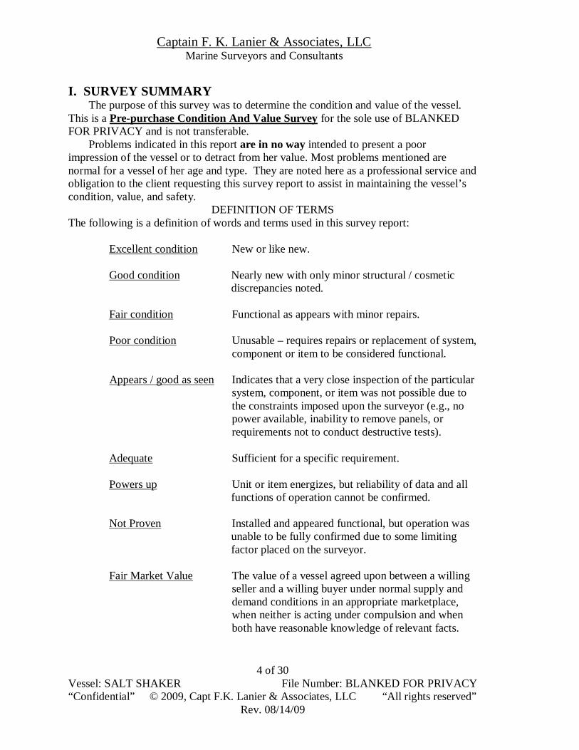
I. SURVEY SUMMARY
The purpose of this survey was to determine the condition and value of the vessel. This is a Pre-purchase Condition And Value Survey for the sole use of BLANKED FOR PRIVACY and is not transferable.
Problems indicated in this report are in no way intended to present a poor impression of the vessel or to detract from her value. Most problems mentioned are normal for a vessel of her age and type. They are noted here as a professional service and obligation to the client requesting this survey report to assist in maintaining the vessel’s condition, value, and safety.
DEFINITION OF TERMS The following is a definition of words and terms used in this survey report:
Excellent condition New or like new.
Good condition Nearly new with only minor structural / cosmetic discrepancies noted.
Fair condition Functional as appears with minor repairs.
Poor condition Unusable – requires repairs or replacement of system,
component or item to be considered functional. Appears / good as seen Indicates that a very close inspection of the particular
system, component, or item was not possible due to the constraints imposed upon the surveyor (e.g., no power available, inability to remove panels, or requirements not to conduct destructive tests).
Adequate Sufficient for a specific requirement.
Powers up Unit or item energizes, but reliability of data and all
functions of operation cannot be confirmed. Not Proven Installed and appeared functional, but operation was
unable to be fully confirmed due to some limiting factor placed on the surveyor.
Fair Market Value The value of a vessel agreed upon between a willing
seller and a willing buyer under normal supply and demand conditions in an appropriate marketplace, when neither is acting under compulsion and when both have reasonable knowledge of relevant facts.

Captain F. K. Lanier & Associates, LLC Marine Surveyors and Consultants
Vessel: SALT SHAKER File Number: BLANKED FOR PRIVACY “Confidential” © 2009, Capt F.K. Lanier & Associates, LLC “All rights reserved”
Rev. 08/14/09
5 of 30
Replacement Value The cost of building a new vessel of like or similar
style in the current market situation and includes applicable freight and taxes.
It is the intent of this survey report to provide an unbiased report of the vessel’s
condition and equipment on the date and time of inspection, not prior to or subsequent to that date and time. A conscientious effort was made to inspect the entire vessel. However, since this report is based only on visual examination of the vessel by non-invasive and non-destructive methods of inspection and diagnosis, this inspection and all contents of this report are not rendered or represented as a warranty or a guarantee of the performance or condition of this vessel, or of any of her machinery, equipment, or systems. Defects not readily visible and not reasonably accessible for inspection or discovery without removal of structure, sheathing, liners, joinery, fittings, tanks, machinery and equipment, especially without disassembling or removing those and any other barriers preventing inspection, are not and can not be covered by this report.
The mandatory standards promulgated by the United States Coast Guard (USCG), as well as the standards and recommendations of the American Boat and Yacht Council (ABYC) Standards and Recommended Practices for Small Craft and the National Fire Protection Association (NFPA) NFPA 302, Pleasure and Commercial Craft have been used as guidelines for this survey and many of the observations and recommendations contained in this report are based on these standards and recommendations, however complete compliance with the above references is neither suggested nor guaranteed.
The observations, opinions, and recommendations contained in this report constitute the entire written survey report as of its date and are intended to supplement and incorporate all prior oral or written comments and communications. If anything in this report is, in the opinion of the above named client, inconsistent with any prior communications from the undersigned, then the client must request clarification as soon as possible or else proceed at his/her own risk. This survey is based on facts observed, discovered and presented at the time of survey and represents the honest and unbiased opinion of the surveyor and neither the surveyor nor his agents are to be held responsible for any inaccuracies, omissions, errors in judgment, or negligence. It is submitted in good faith and in no way offers, expressly or implied, any form of warranty or guarantee concerning the condition of the above mentioned yacht. This survey does not include a determination of the vessel's seaworthiness, nor does it include stability tests or sea trials necessary to such a determination.
Use of this survey constitutes acceptance of all provisions and limitations stated in both this survey report and in the survey contract. All of the provisions of this report are not transferable.

Captain F. K. Lanier & Associates, LLC Marine Surveyors and Consultants
Vessel: SALT SHAKER File Number: BLANKED FOR PRIVACY “Confidential” © 2009, Capt F.K. Lanier & Associates, LLC “All rights reserved”
Rev. 08/14/09
6 of 30
II. DESIGN AND CONSTRUCTION
The hull is of solid fiberglass construction, while the decks and superstructures are a combination of solid and internally cored molded fiberglass. Power is provided by twin diesel engines located port and starboard of centerline beneath the main cabin deck (removable deck panels give reasonable service access to the engines). The layout of the vessel incorporates partial, non-watertight partitions to separate the various internal spaces. These are FRP bonded and/or mechanically fastened to the hull and deck. III. SCOPE OF SURVEY
During the survey of this vessel the hull, decks, and superstructure were inspected both visually and by percussion sounding with a small plastic headed hammer for rot, synthetic filler, loose fastenings, and other defects that would be audibly detected.
This survey neither includes nor implies any certification that the materials and construction methods meet any known standards and the surveyor cannot predict how the vessel will perform over time. It is the builder’s responsibility to warrant the fitness of their product for its intended use and the surveyor does not assume any portion of that warranty. The surveyor has not inspected woodwork or other parts of the structure which are covered, unexposed, or inaccessible and is therefore unable to report that any such part of the structure is free from defect. Design parameters for intended vessel usage are deferred to the designer and manufacturer. Any surveyor comments in this report refer to builder and designer claims and are not the opinion of the surveyor.
Visual inspection of the wetted surfaces of the hull exterior and underwater machinery revealed no damage from impacts, grounding, or galvanic corrosion. The hull was inspected at the hauling facility while blocked in place using typical yard stands and the areas of the hull obscured by these stands were unable to be inspected.
A sea trial or test run is strongly recommended, however as no sea trial was requested by the client, one was not conducted during this survey, meaning the vessel and all its systems and equipment (propulsion, auxiliary machinery, etc) were observed in a static mode only. As the vessel is blocked and hauled ashore, no machinery (engine, generator, etc) was able to be operated.
It must be noted that complete inspection of machinery, plumbing, electrical systems and available equipment can only be made by disassembly or by continuous operation. This has not been done, but may be recommended later in this report. No technical or mechanical tests were performed on propulsion or auxiliary generating equipment by the undersigned and no fluid samples were drawn. Only the installation and external condition of machinery and accessory equipment were inspected. As such, this should not be considered a complete mechanical inspection. Qualified marine mechanics experienced with the specific machinery installed should be employed to survey propulsion engines and auxiliary generators.
Propulsion and rudder shafts were not drawn for inspection, although this may be recommended later in this report. No structural or strength analysis was carried out to determine suitability or capability of any deck working gear (pushing wedge, towing

Captain F. K. Lanier & Associates, LLC Marine Surveyors and Consultants
Vessel: SALT SHAKER File Number: BLANKED FOR PRIVACY “Confidential” © 2009, Capt F.K. Lanier & Associates, LLC “All rights reserved”
Rev. 08/14/09
7 of 30
bars, bitts, etc). The inspection of flexible piping was limited to the condition of its external casing and only where readily accessible for visual inspection
During the interior portion of the survey all loose floorboards were lifted, drawers removed, lockers opened and all accessible interior spaces inspected, however due to construction, finishing methods, modular design, and equipment installations approximately 90% of the interior hull and hull to deck joint was inaccessible and therefore unable to be fully inspected. Due to the above some areas and equipment were not wholly accessible and were unable to be fully inspected. Examples of this include:
1. The fuel tank, water and holding tanks, and associated piping and equipment for each.
2. The generator, including installation and exhaust system. 3. Steering components located in the stern portion of the vessel (rudder posts,
stuffing tubes, jockey-bar, hoses and connections, etc).
Some internal cracked FRP tabbing and indications of possible bulkhead movement were noted for further inspection, however much of the internal hull was obscured (due to construction) and unable to be accessed and inspected.
Electronic and electrical equipment were tested by powering up and observing function, however no measurements were taken and no calibrations or adjustments were made. Batteries were not load tested and only the electrical wiring, connections, and system installation was inspected where visible.
Both AC and DC electrical systems were inspected as noted, however no attempt was made to perform a complete analysis of the boats electrical systems, as this would require disassembly with tools, removals, etc. to gain access to components.
In our experience few boats surveyed today meet all of the applicable standards for marine electrical system fabrication and installation – a situation that can be further aggravated by the corrosive marine environment, poor installations, do-it-yourself add-ons, and a general lack of preventative maintenance. Therefore, when the surveyor’s limited visual inspection of an electrical system raises significant concern regarding standards compliance, the recommendation will be made to employ a qualified, preferably ABYC certified marine electrician to conduct a complete analysis of the vessel’s electrical systems. Attention to compliance with electrical standards is critical to avoiding conditions that may lead to fires, explosions, personal injury, or death.
Fresh water and sanitation systems were visually inspected and tested as noted, however operation of both systems were unable to be fully verified.
Cosmetic or comfort issues are addressed only where there is a significant effect on the vessel’s value. IV. GENERAL COMMENTS
SALT SHAKER looked to have been used with very good care and consideration and no signs of excessive wear and tear, abuse or careless usage were noted.

Captain F. K. Lanier & Associates, LLC Marine Surveyors and Consultants
Vessel: SALT SHAKER File Number: BLANKED FOR PRIVACY “Confidential” © 2009, Capt F.K. Lanier & Associates, LLC “All rights reserved”
Rev. 08/14/09
8 of 30
SALT SHAKER's original design incorporates many desirable traits expected of a vessel of her class and these features are only enhanced by the upgrades and outfitting performed under her current owner, however there were problem areas noted for further inspection and repair that must be addressed. This vessel was manufactured prior to the enactment of some of the USCG, Title 33 requirements, NFPA and ABYC voluntary practices and recommendations in effect today. As such, some of her systems did not meet current standards and will need updating or replacing as described in the body of this report.
This marine survey report addresses those recommendations thought to be necessary for the safety of the vessel and all those onboard, however it does not suggest or imply complete compliance with all current requirements, standards or practices. It must also be noted that the onus to properly equip and operate a vessel lies solely with the owner and/or operator. A search of the US Coast Guard boating safety website www.uscgboating.org revealed no recalls or safety defects listed for this make, model, and year vessel. Information on manufacturer’s defects is available by calling the U.S. Coast Guard’s Boating Safety Hotline, (800)368-5647, or Boat/US at (703)461-2864 Boaters have a responsibility for their own safety that extends well beyond legally mandated safety requirements. Free boating education programs are offered by the U.S. Coast Guard Auxiliary, U.S. Power Squadrons, and some states. For information on courses offered in your area, call Boat/US at (800)336-BOAT or access their web site at www.boatus.com. The U.S. Coast Guard Auxiliary and U.S. Power Squadrons also offer boating instruction online at www.americasboatingcourse.com and via CD-ROM, which can be ordered online or by phone at (866) 262-8222. This course has been approved by the National Association of State Boating Law Administrators and meets the requirements of states (except those that still require classroom instruction) that mandate educational certification to operate a boat. Finally, a wide range of informative articles written by the surveyor on boat operation, maintenance, and repair are available for free under the “Articles” section of our website at www.captfklanier.com.
The following provides vessel information and condition as found during the survey. Recommendations are noted for reference here and listed in their entirety in the “Recommendations” section.

Captain F. K. Lanier & Associates, LLC Marine Surveyors and Consultants
Vessel: SALT SHAKER File Number: BLANKED FOR PRIVACY “Confidential” © 2009, Capt F.K. Lanier & Associates, LLC “All rights reserved”
Rev. 08/14/09
9 of 30
V. SYSTEMS HULL Hull number: BLANKED FOR PRIVACY Location: Starboard transom. Documentation number: 123456 Location: Head compartment. Comments: See recommendation B-1. Hull: Molded FRP (fiber reinforced plastic). Construction: Hull construction is of solid FRP construction. Comments: See recommendation B-2. Finish: Painted topsides and bottom. Comments: Finish is in fair condition with minor cosmetic dings and scratches that warrant repair. The bottom was in the process of being repainted during the survey. Stem: Raked stem of molded FRP. Stern: Transom stern of molded FRP. Keel: Shallow molded FRP keel integral to the hull. Hull to Deck Joint: “Shoe box” type secured with adhesive and mechanical fasteners. Hull to Although the hull to deck joint appeared sound with no visible damage or evidence of separation, stress overload, or working of the joint noted from the outside, the hull to deck joint was unable to be fully inspected from inside due to construction and interior finish work. Decking and superstructure: Combination of solid and internally cored FRP. Vessel trim in water: Not observed. UNDERWATER MACHINERY Rudders: Twin balanced inboard spade rudders Comments: See recommendation B-3. Propeller shaft: 1 ½” stock with shaft nut, backing nut, and cotter pin. Propeller: 3 bladed bronze – port stamped “22-L-22”, starboard stamped “22-R-22” Overall comments: No visible signs of corrosion, electrolysis, or impact damage. Cutless Bearings: Water lubricated rubber sleeve. Comments: No excessive movement noted. Grounding plates: Two Transducers: Five transducers, two speed logs. Comments: No physical, external damage or evidence of leaks noted.

Captain F. K. Lanier & Associates, LLC Marine Surveyors and Consultants
Vessel: SALT SHAKER File Number: BLANKED FOR PRIVACY “Confidential” © 2009, Capt F.K. Lanier & Associates, LLC “All rights reserved”
Rev. 08/14/09
10 of 30
THROUGH HULLS (below static waterline) Note: All through hulls and seacocks are metallic (unless otherwise noted).
1. Type: Holding tank overboard discharge.
Comments: Good as seen. Seacock operational. 2. Type: Unused and capped.
3. Type: Deck wash down intake. Comments: Good as seen. Seacock operational.
4. Type: Starboard engine raw water intake. Comments: Good as seen. Seacock operational.
5. Type: Garboard drain plug. 6. Type: Head raw water intake.
Comments: See recommendation B-4. 7. Type: Port engine raw water intake.
Comments: Good as seen. Seacock operational. 8. Type: AC unit raw water intake.
Comments: Good as seen. Seacock operational. 9. Type: Generator raw water intake.
Comments: See recommendation A-1. THROUGH HULLS (above static waterline) Comments: Combination of metallic and composite through hulls. See recommendation B-5. Overall through hull comments: See recommendation B-6. INTERIOR Hatches: V-berth (19”x18”) and head (9”x 9”). Overall interior comments: All interior finishes and upholstery appear in good physical and cosmetic condition.
Captain F. K. Lanier & Associates, LLC Marine Surveyors and Consultants
Vessel: SALT SHAKER File Number: BLANKED FOR PRIVACY “Confidential” © 2009, Capt F.K. Lanier & Associates, LLC “All rights reserved”
Rev. 08/14/09
11 of 30
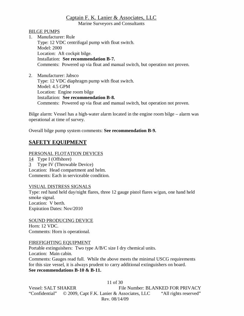
BILGE PUMPS 1. Manufacturer: Rule
Type: 12 VDC centrifugal pump with float switch. Model: 2000 Location: Aft cockpit bilge. Installation: See recommendation B-7. Comments: Powered up via float and manual switch, but operation not proven.
2. Manufacturer: Jabsco
Type: 12 VDC diaphragm pump with float switch. Model: 4.5 GPM Location: Engine room bilge Installation: See recommendation B-8. Comments: Powered up via float and manual switch, but operation not proven.
Bilge alarm: Vessel has a high-water alarm located in the engine room bilge – alarm was operational at time of survey. Overall bilge pump system comments: See recommendation B-9. SAFETY EQUIPMENT PERSONAL FLOTATION DEVICES 14 Type I (Offshore) 3 Type IV (Throwable Device) Location: Head compartment and helm. Comments: Each in serviceable condition.
VISUAL DISTRESS SIGNALS Type: red hand held day/night flares, three 12 gauge pistol flares w/gun, one hand held smoke signal. Location: V berth. Expiration Dates: Nov/2010
SOUND PRODUCING DEVICE Horn: 12 VDC. Comments: Horn is operational. FIREFIGHTING EQUIPMENT Portable extinguishers: Two type A/B/C size I dry chemical units. Location: Main cabin. Comments: Gauges read full. While the above meets the minimal USCG requirements for this size vessel, it is always prudent to carry additional extinguishers on board. See recommendations B-10 & B-11.

Captain F. K. Lanier & Associates, LLC Marine Surveyors and Consultants
Vessel: SALT SHAKER File Number: BLANKED FOR PRIVACY “Confidential” © 2009, Capt F.K. Lanier & Associates, LLC “All rights reserved”
Rev. 08/14/09
12 of 30
Fire extinguisher discharge port: See recommendation B-12. Note: Although not a requirement, it is recommended every vessel carry on board one
2.5 gallon fire bucket with a lanyard of suitable size and length for drawing water from over the vessel’s side. In addition to their primary purpose, a fire bucket is versatile piece of equipment that can serve many functions, such as a bailer or even an emergency toilet.
EMERGENCY POSITION INDICATING RADIO BEACON (EPIRP) Type: CAT II Manufacturer: ACR Model: Satellite2 406 Location: Main cabin. Battery expiration: 7/2005 Serial #: 5649 UIN #: ADCE02184540801 Comments: See recommendations A-2 & A-3 NAVIGATION LIGHTING Running lights: See recommendation A-4. Comments: Unable to completely inspect installation and wiring due to interior finishing. CREW SAFETY AND ERGONOMICS Comments: See recommendation B-13. MACHINERY Note: All technical information taken from published specifications. ENGINES Type: Diesel Make: Caterpillar Model: 3116 (turbo charged). Year: Installed in 1995 as per owner. Serial Numbers: Starboard 4KGO3403 Port 4KG02442 Cylinders: 6 HP: 350 @2800 RPM Engine hours (as per gauges): Starboard 2639 Port 2623 Overhauls: Engines installed new in 1997 as per owner. Reduction Gears: Twin Disc Model: MG 5050-A Ratio: 1.5:1 Engine Mounts: Good as observed in a static mode. Engine Bedworks: Good as seen. Shaft Coupling: Good as seen in a static mode.

Captain F. K. Lanier & Associates, LLC Marine Surveyors and Consultants
Vessel: SALT SHAKER File Number: BLANKED FOR PRIVACY “Confidential” © 2009, Capt F.K. Lanier & Associates, LLC “All rights reserved”
Rev. 08/14/09
13 of 30
Shaft log / hose: Good condition as seen. Comments: The propeller shaft packing glands should be checked regularly (at least weekly depending on use) for excessive dripping or leakage. The stuffing box should be re-packed on a regular basis as part of the vessel’s normal maintenance schedule. Alternators: 2 Engine compartment ventilation: Naturally aspirated. Cooling: Closed freshwater Type: Heat exchanger Cooling system & hoses: Good condition as seen. Raw Water intake strainers: Three - one each, port and starboard engines and generator. Exhaust System: “Wet” type system with transom exit. Comments: See recommendation B-14. Engine Controls: Jacketed push-pull type, dual controls located at helm. Instrumentation: Engine Temp, Engine Oil Pressure, RPMs, Fuel, Hours, Voltmeter. Comments: Located at helm. No instrumentation was verified as boat was hauled. Oil discharge placard: Yes Mechanic’s engine survey: No Engine manual: Yes GENERATOR Type: Diesel Location: Aft beneath cockpit deck on centerline. Manufacturer: Northern Lights Model: TF II 18B Year: Unknown Hours: 1921 (as per gauge). Generator Serial #: GI 11693 Kilowatts: 4.5 Generator transfer switch: Yes Cooling: Closed fresh water with heat exchanger. Exhaust System: Waterlift silencer – wet exhaust. Mounting: Good Carburetor-Flame Arrester: Yes Fuel filter: Racor R205 Comments: Generator is mounted in an enclosure and as such was unable to be fully accessed and inspected. Overall machinery comments: See recommendation B-15.

Captain F. K. Lanier & Associates, LLC Marine Surveyors and Consultants
Vessel: SALT SHAKER File Number: BLANKED FOR PRIVACY “Confidential” © 2009, Capt F.K. Lanier & Associates, LLC “All rights reserved”
Rev. 08/14/09
14 of 30
FUEL SYSTEM Note: All technical information taken from published specifications and/or tank manufacturer’s label. Number of tanks: 1 Reported capacity: 325 gallons Material: FRP Shape: Rectangular Location: Beneath cockpit deck. Mounting: Framed in place. Manufacturer’s label: No Overboard vent discharge: Yes Comments: The vent is connected to the fuel tanks with a rubber hose not labeled as to application type. The vent hose connection at the fuel vent fitting was not seen. Fuel hose type: Mix of USCG Type A-I and Aeroquip hoses. Fuel Shut Off Valves: Yes Location: At tank. Overall comments: There were no visible indications of fuel leaks in the bilge, however access to the fuel tank was limited, meaning construction details and condition of the fuel tank could not be determined within the limits of this inspection. ELECTRICAL SYSTEMS DC ELECTRICAL SYSTEM Batteries: 2 Type: Wet cell Location: Centerline beneath cockpit deck. Size: W-8D Voltage: 12 VDC Installation: See recommendation B-16. Wiring: Multi-stranded jacketed copper wire. Charging systems: Engine alternators and battery charger. Battery charger: Guest Model: 16202 Location: Engine room. Condition: New unit. Comments: Unit was mounted, but not yet connected or ready for use. Battery Switch: See recommendation B-17. Circuit Protection: Individual branch circuit breakers. Location: Main cabin
Captain F. K. Lanier & Associates, LLC Marine Surveyors and Consultants
Vessel: SALT SHAKER File Number: BLANKED FOR PRIVACY “Confidential” © 2009, Capt F.K. Lanier & Associates, LLC “All rights reserved”
Rev. 08/14/09
15 of 30
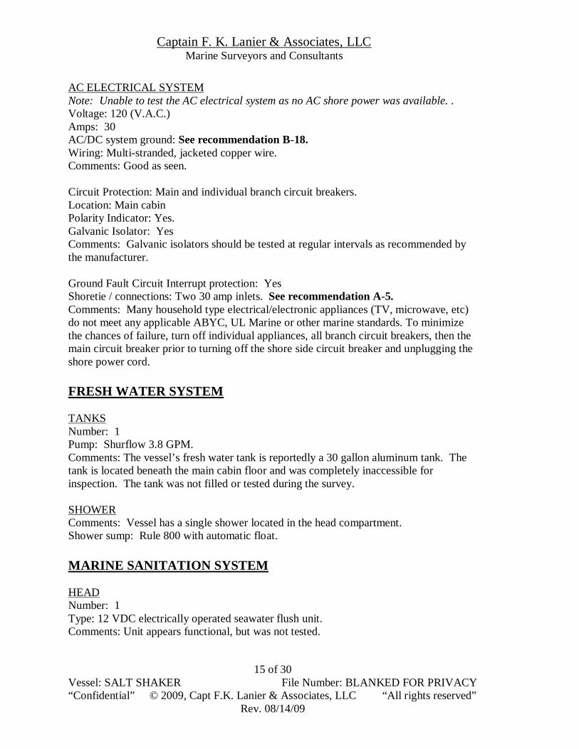
AC ELECTRICAL SYSTEM Note: Unable to test the AC electrical system as no AC shore power was available. . Voltage: 120 (V.A.C.) Amps: 30 AC/DC system ground: See recommendation B-18. Wiring: Multi-stranded, jacketed copper wire. Comments: Good as seen. Circuit Protection: Main and individual branch circuit breakers. Location: Main cabin Polarity Indicator: Yes. Galvanic Isolator: Yes Comments: Galvanic isolators should be tested at regular intervals as recommended by the manufacturer. Ground Fault Circuit Interrupt protection: Yes Shoretie / connections: Two 30 amp inlets. See recommendation A-5. Comments: Many household type electrical/electronic appliances (TV, microwave, etc) do not meet any applicable ABYC, UL Marine or other marine standards. To minimize the chances of failure, turn off individual appliances, all branch circuit breakers, then the main circuit breaker prior to turning off the shore side circuit breaker and unplugging the shore power cord. FRESH WATER SYSTEM TANKS Number: 1 Pump: Shurflow 3.8 GPM. Comments: The vessel’s fresh water tank is reportedly a 30 gallon aluminum tank. The tank is located beneath the main cabin floor and was completely inaccessible for inspection. The tank was not filled or tested during the survey. SHOWER Comments: Vessel has a single shower located in the head compartment. Shower sump: Rule 800 with automatic float. MARINE SANITATION SYSTEM HEAD Number: 1 Type: 12 VDC electrically operated seawater flush unit. Comments: Unit appears functional, but was not tested.

Captain F. K. Lanier & Associates, LLC Marine Surveyors and Consultants
Vessel: SALT SHAKER File Number: BLANKED FOR PRIVACY “Confidential” © 2009, Capt F.K. Lanier & Associates, LLC “All rights reserved”
Rev. 08/14/09
16 of 30
HOLDING TANKS Number: 1 Locations: Engine room. Material: Polyethylene Estimated capacity: 20 gallons Hoses: Marine grade sanitation hose Y-Valve: Yes – federal regulations require either the Y valve be secured in the holding tank position or that the overboard discharge be secured in the closed position. Macerator pump: Yes – not proven. Discharge and Dockside Pump-out: Yes System comments: Head and sanitation system appears functional. All marine sanitation system seacocks should be closed when head is not in use to prevent possible back siphoning and flooding. GALLEY Layout: “L” shaped with single sink, pressure water, Norcold refrigerator and Kenmore microwave. Comments: Pressure water and refrigerator operational. Unable to test microwave due to lack of AC power. MARPOL Trash Placard: Yes CO Detector: No Smoke Detector: No Comments: See recommendation A-6. ELECTRONICS Note: All units were powered up and appear functional (unless otherwise noted) however no technical testing or verification of functionality was conducted VHF RADIO Manufacturer: Standard Serial #: Not sighted due to installation. Location: Helm Comments: Powers up. Manufacturer: Icom Model: IC-M 100 Serial #: Not sighted due to installation. Location: Helm Comments: Powers up.

Captain F. K. Lanier & Associates, LLC Marine Surveyors and Consultants
Vessel: SALT SHAKER File Number: BLANKED FOR PRIVACY “Confidential” © 2009, Capt F.K. Lanier & Associates, LLC “All rights reserved”
Rev. 08/14/09
17 of 30
DEPTH SOUNDER / SPEED LOG Manufacturer: Datamarine Model: DM 600 Serial #: Not sighted due to installation. Location: Helm Comments: Powers up. GPS Manufacturer: Furuno Model: GP – 1850DF Serial #: 3420-2394 Location: Helm Comments: Powers up. Manufacturer: Furuno Model: GPS Navigator Serial #: 3401-7523 Location: Helm Comments: Powers up. RADAR Manufacturer: Furuno Model: 1830 Serial #: 2321-3918 Location: Helm Comments: Powers up. INSTRUMENTATION COMPASS Manufacturer: Ritchie Model: High Speed Location: Helm Comments: See recommendation B-19. AIR CONDITIONING Manufacturer: Cruisar Number: Two BTU: 16,000 each Location: Beneath cockpit deck, port and starboard. Installation: See recommendation B-20. Comments: Both units appear operational, but were unable to be tested as vessel was hauled.

Captain F. K. Lanier & Associates, LLC Marine Surveyors and Consultants
Vessel: SALT SHAKER File Number: BLANKED FOR PRIVACY “Confidential” © 2009, Capt F.K. Lanier & Associates, LLC “All rights reserved”
Rev. 08/14/09
18 of 30
HEATING Comments: Vessel has a forced air induction style heater located in the main cabin. Unit appears operational, but was unable to be tested due to lack of AC power. STEERING SYSTEM Type: Hydraulic ram to jockey bar and dual rudders. Manufacturer: Hynautic Comments: System appears sound and serviceable as observed in a static position. Regular inspections of the steering system should be incorporated into the vessel’s maintenance schedule. GROUND TACKLE AND CORDAGE Note: Rodes and chains were not pulled or inspected except as noted. All lengths are estimates. PRIMARY ANCHOR / RODE Manufacturer: Fortress Type: FX 16 Chain: 20 ft of 3/8” galvanized Rode: 150 ft. of 3/4” three stranded nylon. Location: Anchor mounted on bow, with rode attached and stored below in forepeak. Swivel: No All shackles moused: No Bitter end attached: Yes Comments: See recommendation A-7. WINDLASS Type: 12 VDC Manufacturer: Simpson Lawrence Condition: Powers up and appears operational. DECK DECK HARDWARE Material: Stainless steel Mounting: Good as seen Comments: Four 8 ½” cleats ranged along the bow and amidships port and starboard side with two 10” cleats located port and starboard at the stern. HAND RAILS Comments: Mounting is good with rails adequately placed about the vessel.
Captain F. K. Lanier & Associates, LLC Marine Surveyors and Consultants
Vessel: SALT SHAKER File Number: BLANKED FOR PRIVACY “Confidential” © 2009, Capt F.K. Lanier & Associates, LLC “All rights reserved”
Rev. 08/14/09
19 of 30
VI. RECOMMENDATIONS The following recommendations are made in accordance with NFPA-302, ABYC, and applicable USCG codes and have been divided into priorities for the purpose of planning maintenance and repair.
First priority items (preceded by an “A”) are listed in section A and pertain to safety or vessel integrity issues which should be completed either before operation of the vessel or prior to leaving her unattended at a dock or mooring, depending on the nature of the recommendation.
Secondary items (preceded by a “B”) are listed in section B and pertain to deficiencies in state and/or federal regulations, as well as maintenance or improvement recommendations that should be completed within the next year or sooner (as dictated by need and circumstance) unless otherwise noted. Surveyor comments (preceded by a “C”) are pertinent suggestions and good general advice provided as a courtesy to the client. SECTION A: First Priority Recommendations A-1 The raw water intake hose for the generator is deteriorated and in poor
condition. Recommend it be replaced prior to launch by a competent marine technician.
A-2 The battery for the EPIRP has expired. Recommend the unit be returned to an
authorized service facility for battery replacement and servicing. A-3 The NOAA registration sticker for the EPIRB is expired and lists the vessel’s
previous name (all EPIRBs coded in the US are required by law to be registered with NOAA). Recommend that the EPIRB be registered with NOAA and all vessel data and owner contact info be updated – this can be done online at http://www.sarsat.noaa.gov/beacon.html .
A-4 The port running light and the anchor light were inoperative at time of survey.
Additionally, the port and starboard running light fixtures are loose and the clarity of the lenses has diminished due to age. Recommend the following be completed by a competent marine technician:
A-4.1 Repair the port running light and anchor light. A-4.2 Replace the lenses for the port and starboard running lights. A-5 There is no warning label at the shore power receptacle. Recommend providing a permanently mounted waterproof label stating:
WARNING Electrical shock and fire hazard.Failure to follow these instructions may result in injury or death. (1) Turn off the boat's shore power connection switch before connecting or disconnecting the shore power cable.

Captain F. K. Lanier & Associates, LLC Marine Surveyors and Consultants
Vessel: SALT SHAKER File Number: BLANKED FOR PRIVACY “Confidential” © 2009, Capt F.K. Lanier & Associates, LLC “All rights reserved”
Rev. 08/14/09
20 of 30
(2) Connect shore power cable at the boat first.
(3) If polarity-warning indicator is activated, immediately disconnect cable. (4) Disconnect shore power cable at shore outlet first. (5) Close shore power inlet cover tightly. DO NOT ALTER SHORE POWER CABLE CONNECTORS A-6 Marine grade Smoke and Carbon monoxide detectors are recommended for all boats with enclosed accommodation compartments as per ABYC 24.7.1. and NFPA 302 12.3, which states “All vessels 26 ft (8 m) or more in length with accommodation spaces intended for sleeping to be equipped with a single station smoke alarm that is listed to UL 217, Standard for Single and Multiple Station Smoke Alarms, for recreational vehicles and is installed and maintained according to the device manufacturer’s instructions.” This vessel uses fossil fuels for propulsion and during the burning of these fuels Carbon Monoxide (CO) gas may be created due to incomplete combustion. Adequate ventilation must be provided at all times while burning any of these fuels, but CO may also be drawn into the cabin through ventilation systems. Although diesel exhaust does not normally have CO concentration as high as gasoline exhaust, diesel exhaust does produce dangerous levels of CO. Any open-flame equipment as well as nearby boats running generators could also be a source of dangerous amounts of CO. This is especially true of boats running air conditioning. Marine CO monitor/alarms meeting the requirements of ABYC A-24, Carbon Monoxide Detection Systems on boats are relatively inexpensive and easy to install. Possible choices include the Xintex model CMD-3M, Marine Technologies model 60-542 or equivalent that meets UL Standard #2034. As many boaters utilize generators to power air conditioners and other appliances while at anchor, an even better option would be a CO alarm system (such as made by MariTech Industries - www.maritechsafety.com) designed to shut off the generator once CO is detected. CO is a silent menace that kills without warning, therefore this surveyor recommends installation of suitable marine grade CO and smoke detectors (located to monitor the atmosphere in the main cabin and each sleeping area) by a competent marine technician. Note: The following general safety recommendations concerning the dangers of carbon monoxide apply to all vessels and in particular to houseboats and/or similarly constructed vessels - deaths have been linked to carbon monoxide emission aboard such vessels in the past.
1. Stay out of areas where carbon monoxide can collect while the engine or generator is running and for at least an hour afterwards. The Coast Guard advises owners and operators of boats to turn off generators with transom exhaust ports when the swim platform on the stern is in use.

Captain F. K. Lanier & Associates, LLC Marine Surveyors and Consultants
Vessel: SALT SHAKER File Number: BLANKED FOR PRIVACY “Confidential” © 2009, Capt F.K. Lanier & Associates, LLC “All rights reserved”
Rev. 08/14/09
21 of 30
2. Do not allow swimmers near exhaust portals or in areas where air pockets may be located under the boat. Swimmers should avoid the area beneath transom swimming platforms or rear decks while the engine or generator is running; if exhaust vents are located on the vessel’s side, these areas should be avoided as well. Adults should keep a close watch on children at all times, particularly when they are playing or swimming in the swim platform area. As a general rule, passengers or crew should not be allowed to sit on swim platforms while the vessel’s engine(s) or generator is running.
3. Use caution when boats are tied together, as carbon monoxide generated in one vessel can enter other nearby vessels via air condition intakes, open portholes, etc.
4. Know the signs of carbon monoxide poisoning (headache, dizziness, weakness, nausea, dry mouth, confusion, etc) and if carbon monoxide poisoning is suspected, relocate the victim to an area of fresh aid and seek medical attention immediately.
5. Read and obey all carbon monoxide warnings placed on generators and engines by the manufacturer and never tamper with or disconnect carbon monoxide detectors or monitors.
6. Turn off the generator prior to going to sleep AND turn off the main AC breaker so "demand start" generators will not start during the night.
7. It is also recommended that a warning decal about CO (carbon monoxide) be placed so as to be visible to the operator and a second decal about CO and teak surfing be placed on the exterior of the stern or transom of all motor vessels.
A-7 The anchor shackle is not moused and the plastic eye thimble for the rope to chain
connection is damaged. Recommend the thimble be replaced and that all anchor rode shackles be moused with stainless steel wire by a competent marine technician.
SECTION B: Secondary Priority Recommendations B-1 The vessel’s documentation number was not properly displayed. The official
number assigned to documented vessels must be permanently affixed so that alteration, removal, or replacement would be obvious and cause some scarring or damage to the surrounding hull area. Additionally the year of construction indicated by the hull number (1982) does not match that shown on the documentation paperwork (1980). Recommend the vessel’s documentation number be applied as per CG regulations and that the year of construction listed on the documentation be corrected.
Captain F. K. Lanier & Associates, LLC Marine Surveyors and Consultants
Vessel: SALT SHAKER File Number: BLANKED FOR PRIVACY “Confidential” © 2009, Capt F.K. Lanier & Associates, LLC “All rights reserved”
Rev. 08/14/09
22 of 30
B-2 Broken stringer, floor, and bulkhead FRP tabbing were sighted in the engine
compartment outboard of both the starboard engine (see photos B-2.A & B) and port engine (see photo B-2.C). An approximately 2 inch crack was also sighted in the bulkhead forward and outboard of the port engine (see photo B-2.D). The above are typical indications of excessive hull flexing and movement. As it appears the vessel was originally powered with gasoline engines, the flexing is likely due to the installation of heavier, more powerful diesel engines during the vessel’s repower. If that is the case, repairs of the damaged areas must be designed to exceed their original strength to prevent future failures. Recommend each of the above areas be inspected, evaluated, and repaired using best industry practice by a competent marine repair facility.
B-3 Evidence of leaking was noted at the starboard rudder post. Recommend the
rudder post and packing gland be inspected and repacked or repaired by a competent marine repair facility. Rudder packing glands should be checked regularly (at least monthly depending on use) for excessive dripping or leakage. They should also be re-packed on a regular basis as part of the vessel’s normal maintenance schedule.
B-4 The head raw water intake utilizes a gate valve for the seacock. ABYC
recommends that all seacocks meet UL 1121 and ABYC H-27 standards and recommendations, which include operation by a lever type handle (usually operating through a 90° arc) that gives a clear indication of whether the seacock is open or shut, and a mounting that will withstand a 500 pound force applied at the inner end of the attached fitting. Recommend having a competent marine technician replace the gate valve with a proper, marine grade seacock as defined by the ABYC recommendation above. Flanged, bronze type seacocks are recommended, as is replacement of the corresponding through hull (to prevent the possibility of thread mismatch). Seacocks and their respective through hull must also be of the same material.
B-5 The composite through hulls above the waterline appear original and are
beginning to show signs of UV degradation. Recommend starting a replacement schedule so that all composite through hulls are replaced within the next year (or sooner if dictated by need and circumstance).
B-6 Recommend the following be completed by a competent marine technician B-6.1 Install double, marine grade stainless steel or titanium clamps on all
through hull and seacock hoses where possible. B-6.2 Locate soft tapered wood plugs of appropriate size at every through
hull fitting below the waterline – these plugs can be either mounted or attached with light line. Another option is storage in a portable “Damage Control” kit.

Captain F. K. Lanier & Associates, LLC Marine Surveyors and Consultants
Vessel: SALT SHAKER File Number: BLANKED FOR PRIVACY “Confidential” © 2009, Capt F.K. Lanier & Associates, LLC “All rights reserved”
Rev. 08/14/09
23 of 30
B-6.3 Perform periodic disassembly and internal inspection of through hull fittings, hoses, and valves on a rotating basis each time the vessel is hauled. Recommend this inspection include a static test conducted on each through hull fitting to determine degree of deterioration /degradation for both metal and composite fittings.
B-6.4 Hose has a limited lifespan and in general should be replaced every 5 years. As some of the through hull hoses appear to be original installs, recommend implementing a replacement schedule for all through hull hoses such that all greater than five years of age are replaced within the next year or sooner (as dictated by need and circumstance).
Finally, it is recommended that all through hull seacocks be closed when the system it serves is not being used, particularly when the vessel is left unattended while in the water. Note: Where installation of double hose clamps are recommended throughout this report, it is understood that double clamps should only be installed where there is sufficient length of barb/nipple available and hose end overlap to allow it. As per ABYC, no clamp shall be installed closer than 1/4" to the end of the hose and must fully engage the barb or fitting. Any clamp that extends over the end and is cutting into the hose or forcing the hose to be internally cut by the fitting is an incorrect installation. In such cases, replace the fitting with one having a longer barb/nipple to facilitate installation of double clamps (preferred) or install a single clamp of the appropriate size. Clamps should be separated by at least ¼” (½” if possible) with screws located on opposite sides of the hose. For a clamp to perform at its optimal level, the clamp should be installed at the manufacturer's recommended installation torque. Insufficient clamping force allows fluid to seep in between the joint and the hose I.D. increasing the risk of blow-off, while over tightening clamps can cause damage to the hose and/or clamp itself. B-7 Recommend the missing mounting screw for the aft bilge pump automatic float
switch be replaced by a competent marine technician. B-8 Recommend the strum box (intake filter) for the engine compartment bilge
pump be mounted in the bilge to prevent movement. B-9 Recommend the following be carried out by a competent marine technician:
B-9.1 Install a visual “bilge pump on” indicator for each electric bilge pump at the helm.
B-9.2 Test and verify operation of the high water bilge alarm at regular intervals (monthly at a minimum).
B-9.3 Install riser loops in all bilge pump discharge hoses to a level at least 12” above the hull’s maximum heeled waterline to prevent possible back siphoning.

Captain F. K. Lanier & Associates, LLC Marine Surveyors and Consultants
Vessel: SALT SHAKER File Number: BLANKED FOR PRIVACY “Confidential” © 2009, Capt F.K. Lanier & Associates, LLC “All rights reserved”
Rev. 08/14/09
24 of 30
B-9.4 Where possible, double clamp all bilge pump hoses at each transition point and at both ends with marine grade stainless steel or titanium clamps.
B-9.5 Test and verify operation of all bilge pump systems now and at regular intervals in the future, monthly at a minimum. Testing should verify the actual pumping of water overboard, rather than (in the case of electric pumps) simply switching the pump on and listening for motor operation.
B-9.6 Hose has a finite lifespan and in general should be replaced every 5 years. As some appear to be original installs, recommend implementing a replacement schedule for bilge pump system hoses such that all greater than 5 years of age are replaced within the next year or sooner (as dictated by need and circumstance).
B-10 Recommend both portable fire extinguishers be inspected now by a qualified
service facility and at regular intervals in the future as per NFPA 302 (annually at a minimum). Portable extinguishers of this type should be considered disposable and in general replaced after five years of service (based on condition of the unit and test results).
B-11 As per ABYC standards, recommend a fire extinguisher be installed in the cockpit or at the helm. This ensures an extinguisher will be available in the event a fire blocks access to the main cabin (currently all extinguishers are located inside the main cabin). B-12 ABYC standards recommend provisions for discharging a suitably sized clean agent portable fire extinguisher directly into the space immediately surrounding the engines without opening the primary access panels (if an appropriately sized fixed automatic "clean agent" (i.e. CO2, Halotron®, FM-200, FE-241) fire extinguisher is not installed in the engine compartment). The discharge port must be sized to accept the portable fire extinguisher discharge nozzle, able to be opened from outside the compartment to provide ready access for discharge of the agent into the engine compartment, and located so the required size portable fire extinguisher can be properly discharged in accordance with the manufacturer's instructions. The fire extinguisher must also be of sufficient size to service the entire engine compartment. Recommend installation of a discharge port and fire extinguisher as per the above by a competent marine technician. B-13 No re-boarding device was sighted. ABYC recommendations state that a means of unassisted re-boarding shall be provided on all boats for the purpose of re- boarding the boat from the water. Re-boarding means must be accessible to, and deployable by, the person in the water. This may include, but is not limited to, steps, swim platforms, handhold devices, grab rails, or ladders. The top surface of the lowest step of a re-boarding ladder, if installed to meet the requirement of

Captain F. K. Lanier & Associates, LLC Marine Surveyors and Consultants
Vessel: SALT SHAKER File Number: BLANKED FOR PRIVACY “Confidential” © 2009, Capt F.K. Lanier & Associates, LLC “All rights reserved”
Rev. 08/14/09
25 of 30
this standard, must be at least 12 inches below the waterline with the boat in the static floating position. Recommend the vessel always carry a re-boarding ladder
or other device meeting the above recommendations. COB (crew overboard) retrieval planning should include various scenarios, such as recovery of an incapacitated victim. It is crucial that COB and recovery drills are not only understood by all onboard, but practiced on a regular basis – include captain and crew role reversals to ensure recovery can take place if the captain is incapacitated or the COB. Ensure a boarding ladder can always be easily deployed and that all hardware is kept in serviceable condition. B-14 Evidence of a small leak (in the form of rust stains) was noted at the starboard
engine exhaust elbow. Recommend this leak be investigated and repaired by a competent marine mechanic
B-15 While no technical inspection of the engines, generator, or reduction gears was performed a visual inspection was conducted and the following observations were made. The engine compartment was in general well organized and overall installations looked sound and serviceable, however the presence of oil in the generator cabinet indicates the possibility of an oil leak. Recommend each of the following be conducted by a competent marine mechanic.
B-15.1 Recommend the cause of the oil in the generator cabinet be investigated and corrected.
B-15.2 Although the generator exhaust system was visually inspected to the extent possible by the surveyor, components that are internally damaged or failing (due to corrosion, defects, etc) often can not be detected by visual inspection alone.
Due to the known cases of CO (Carbon Monoxide) poisoning that have occurred as a result of exhaust fumes leaking into a vessel’s interior, recommend that the entire generator exhaust system be disassembled and thoroughly inspected. B-15.3 Install chafe protection for all engine and generator wires and hoses where necessary and ensure that all fuel, cooling, and exhaust hoses
are double clamped with marine grade stainless steel clamps where possible and provided chafe protection at all bulkhead or other such transition points.
B-15.4 Fuel lines and other such hoses have a finite lifespan and in general should be replaced every 5 years. As most appear to be original installs, recommend implementing a replacement schedule for all engine and generator cooling, fuel, and exhaust system hoses such that all greater than five years of age are replaced within the next year (or sooner if dictated by need and circumstance).

Captain F. K. Lanier & Associates, LLC Marine Surveyors and Consultants
Vessel: SALT SHAKER File Number: BLANKED FOR PRIVACY “Confidential” © 2009, Capt F.K. Lanier & Associates, LLC “All rights reserved”
Rev. 08/14/09
26 of 30
B-16 NFPA 302 and ABYC standards require that all batteries be installed in liquid
tight, acid- proof boxes, be properly secured, and have all exposed positive terminals covered to prevent accidental shorting. Recommend having a competent marine technician install proper battery boxes or trays, secure the batteries so that movement is no greater than 1 inch in any direction, and install rubber “boots” or a non-conductive shield over each exposed positive terminal. (battery box covers will satisfy this requirement).
B-17 There are no battery switches installed. ABYC 11.7.1.2.1 requires a battery
switch be installed in the positive conductor from each battery or battery bank with a CCA rating greater than 800 amperes. Recommend installation of suitable battery switchs by a competent marine electrician.
B-18 ABYC 11.5.3.3. states the main AC system grounding bus shall be connected to the engine negative terminal or the DC main negative bus on grounded DC systems, or the boat’s DC grounding bus in installations using ungrounded DC electrical systems. This AC to DC ground was not sighted. Recommend it be verified or installed if not in place by an ABYC certified marine electrician. B-19 There is no deviation card for the compass and the surveyor was unable to verify operation of the compass light due to bright conditions during the survey. B-19.1 Verify operation of the compass light (this can easily be done at night) and repair if inoperable. B-19.2 Swing the compass or have a compass adjuster perform the process and post the deviation card. B-20 Recommend the clear vinyl hose used in the air conditioning cooling water
intake be replaced with hose suitable for marine grade use below the waterline by a competent marine technician.
SECTION C: Surveyor Comments C-1 All seacocks should be exercised at least monthly to ensure proper operation and each should be completely removed, disassembled and inspected every three to four years, at which time all clamps and hose ends should be inspected for corrosion, cracks, or other damage and replaced as necessary. Through-hulls should be removed and inspected at this time as well, which ensures bedding compounds are renewed at appropriate intervals. C-2 Plastic through hull fittings installed at or above the water line are subject to breakage while docking, being struck by floating object/s and potential UV light damage. Consider replacement with bronze or stainless steel fittings and seacocks (if subject to submersion while heeling).
Captain F. K. Lanier & Associates, LLC Marine Surveyors and Consultants
Vessel: SALT SHAKER File Number: BLANKED FOR PRIVACY “Confidential” © 2009, Capt F.K. Lanier & Associates, LLC “All rights reserved”
Rev. 08/14/09
27 of 30
C-3 Installation of a larger capacity back-up electric bilge pump is highly desirable.
Back up pumps should ideally be mounted and configured to turn on when bilge water level reaches around 4 to 6 inches above the cut on point for the primary pump. This prevents the back up pump from resting in the normal accumulation of bilge water, where it can become clogged with sludge and debris or seized from disuse.
C-4 Regular inspections of the bilge pump systems should be included in the vessel’s
overall preventative maintenance program, enabling the replacement of worn or damaged components at prescribed intervals rather than upon failure. C-5 Although not a USCG requirement, an appropriately sized fixed automatic "clean agent" (i.e. CO2, Halotron®, FM-200, FE-241) fire extinguisher mounted in the engine compartment would be a very desirable safety upgrade. NFPA Standard 302, Chapter 10.2-10.3, and ABYC Standard A-4.5.2 specify that "enclosed machinery spaces (engine compartments) be protected either by a fixed, automatic fire extinguishing system or by a portable "clean agent" [CO2, Halotron®, FM-200, FE-241] extinguisher. If a portable extinguisher is provided to meet this standard, a port must be provided through which the portable extinguisher can be discharged directly into the machinery space without opening the primary access." C-6 Life jackets should be stored in convenient locations throughout the vessel.
Stowage compartments or containers for life jackets should not be capable of being locked and if practicable should be designed to allow the life jackets to float free in the event the vessel sinks. Child size life jackets should be appropriately marked and separated from adult life jackets (to the extent practical) to prevent them from being mistaken for adult life jackets.
C-7 Raw water intake strainers are sometimes joined together with threaded rods that are not of the same material as the housing, which can result in galvanic corrosion. Each strainer should be disassembled at regularly scheduled intervals for maintenance and fully inspected by a competent marine technician for corrosion or damage – if any is found, repair or replaced unit as necessary. C-8 Engine manifolds and exhaust risers should be periodically removed, pressure tested, and fully inspected by a qualified marine mechanic for leaks, corrosion, and clogging, as failure here can easily cause catastrophic engine failure. This should be considered standard maintenance, particularly with systems operating in salt water. How often depends on vessel location and use, however at a minimum they should be removed every four years (more frequently depending on age), pressure tested, and inspected by a qualified marine mechanic.

Captain F. K. Lanier & Associates, LLC Marine Surveyors and Consultants
Vessel: SALT SHAKER File Number: BLANKED FOR PRIVACY “Confidential” © 2009, Capt F.K. Lanier & Associates, LLC “All rights reserved”
Rev. 08/14/09
28 of 30
C-9 All onboard tanks (fuel, water, holding, etc) and their associated system
components should be pressure tested for leaks on a regular basis (every five years minimum) by a competent marine service facility.
C-10 Installation of a galvanic isolator “status monitor” as per ANSI/ABYC A-28 by
an ABYC certified marine electrician should be considered. Status monitors should be installed within easy view (so they can be monitored frequently) and tested for proper function of the isolator unit, failure to block galvanic current, continuity of the green wire ground, reverse polarity, connectivity of both AC and DC ground systems, AC ground wire ground currents, and failure of the monitoring system itself. The galvanic isolator should also be tested by an ABYC certified marine electrician for proper operation and at regular, future intervals recommended by him.
C-11 Lightning protection is a topic of great debate among marine professionals, both
for and against. If a vessel owner opts to install a lightning protection system, the installation should meet all applicable ABYC Standards, particularly ABYC E-4, “Lightning Protection.” It should also be noted that complete protection from equipment damage or personal injury is not implied with any lightning protection system.
VII. CONCLUSION
In our opinion, once the required items listed in the “Recommendations” section have been corrected, this vessel should be suitable for service within limitations defined by design and construction provided prudent routine and preventative maintenance is performed and the boat is operated by competent crew with due regard to customary safety practices, good seamanship, and prevailing weather conditions. Issued without prejudice,
Captain Frank K. Lanier

Captain F. K. Lanier & Associates, LLC Marine Surveyors and Consultants
Vessel: SALT SHAKER File Number: BLANKED FOR PRIVACY “Confidential” © 2009, Capt F.K. Lanier & Associates, LLC “All rights reserved”
Rev. 08/14/09
29 of 30
Helm
Main cabin (starboard)
Galley
Forward cabin
Head
Starboard engine

Captain F. K. Lanier & Associates, LLC Marine Surveyors and Consultants
Vessel: SALT SHAKER File Number: BLANKED FOR PRIVACY “Confidential” © 2009, Capt F.K. Lanier & Associates, LLC “All rights reserved”
Rev. 08/14/09
30 of 30
Port engine
Generator
B-2.A
B-2.B
B-2.C
B-2D