Embed Size (px)
Citation preview
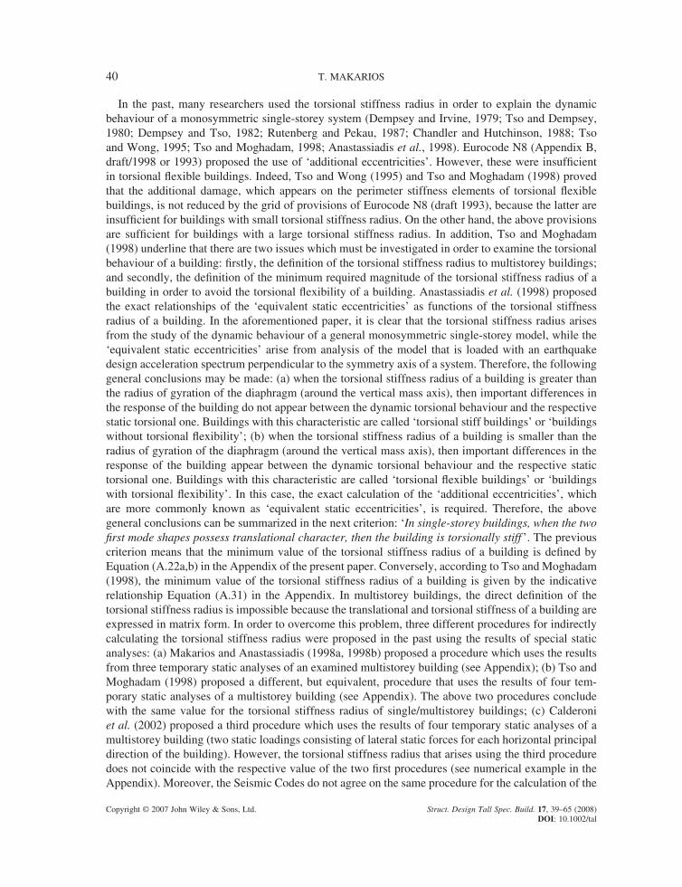
PRACTICAL CALCULATION OF THE TORSIONAL STIFFNESS RADIUS OF MULTISTOREY TALL BUILDINGS
T. MAKARIOS*Institute of Engineering Seismology and Earthquake Engineering, Thessaloniki, Greece
SUMMARY
The present paper refers to the defi nition of the torsional stiffness radii of multistorey tall buildings using both the continuous and the discrete model of the structure. The magnitude of the torsional stiffness radius of a building is the most important structural characteristic in order to explain the torsional behaviour of a building during an earthquake as it directly affects the building’s torsional fl exibility. The importance of the torsional fl exibility of buildings is recognized by contemporary Seismic Codes that propose a grid of torsional provisions in order to avoid soft-storey operation due to fl oor torsional vibrations around a vertical axis. However, contrary to single-storey buildings, the torsional stiffness radius of multistorey buildings is not defi ned directly because both the translational and torsional stiffness of these buildings are expressed in matrix form. In the present paper, this weakness has been overcome using the continuous model of the structure, from which the torsional stiff-ness radius of a general monosymmetric multistorey tall system arises via a closed mathematical equation. The discrete model of the structure has numerically verifi ed this closed mathematical equation. Copyright © 2007 John Wiley & Sons, Ltd.
Keywords: torsional stiffness radii; multistorey buildings; fi ctitious elastic axis of multistorey buildings
1. INTRODUCTION
Very often damage has been systematically reported on the perimeter of buildings due to strong earthquakes and this fact is due to intense fl oor torsional vibrations around the vertical axis of build-ings. Indeed, fl oor torsional vibrations cause additional displacements on the perimeter of buildings and these, in turn, increase displacements caused by the respective pure translational vibrations. Compared to the respective demands of ductility due to the pure translational vibration of buildings, the untimely yield of the perimetric structural elements and their additional demands of ductility are caused by the additional displacements on the perimeter of the building from above. The explanation of the torsional behaviour of a building can be achieved using the torsional stiffness radius, which is the most important characteristic of the building. Indeed, the torsional stiffness radius is more impor-tant than the static eccentricity of the building because, for translational base excitation, when the torsional stiffness radius is large the translational (not torsional) vibration of the fl oors of buildings dominates irrespective of the magnitude of the static eccentricity of the building. Conversely, when the torsional stiffness radius of a building is small, then the fl oor torsional vibration dominates (for translational base excitation).
Copyright © 2007 John Wiley & Sons, Ltd.
* Correspondence to: T. Makarios, Institute of Engineering Seismology & Earthquake Engineering (ITSAK), PO Box 53, GR-55102 Finikas, Thessaloniki, Greece. E-mail: [email protected]
THE STRUCTURAL DESIGN OF TALL AND SPECIAL BUILDINGSStruct. Design Tall Spec. Build. 17, 39–65 (2008)Published online 24 September 2007 in Wiley Interscience (www.interscience.wiley.com). DOI: 10.1002/tal.316
40 T. MAKARIOS
Copyright © 2007 John Wiley & Sons, Ltd. Struct. Design Tall Spec. Build. 17, 39–65 (2008) DOI: 10.1002/tal
In the past, many researchers used the torsional stiffness radius in order to explain the dynamic behaviour of a monosymmetric single-storey system (Dempsey and Irvine, 1979; Tso and Dempsey, 1980; Dempsey and Tso, 1982; Rutenberg and Pekau, 1987; Chandler and Hutchinson, 1988; Tso and Wong, 1995; Tso and Moghadam, 1998; Anastassiadis et al., 1998). Eurocode N8 (Appendix B, draft/1998 or 1993) proposed the use of ‘additional eccentricities’. However, these were insuffi cient in torsional fl exible buildings. Indeed, Tso and Wong (1995) and Tso and Moghadam (1998) proved that the additional damage, which appears on the perimeter stiffness elements of torsional fl exible buildings, is not reduced by the grid of provisions of Eurocode N8 (draft 1993), because the latter are insuffi cient for buildings with small torsional stiffness radius. On the other hand, the above provisions are suffi cient for buildings with a large torsional stiffness radius. In addition, Tso and Moghadam (1998) underline that there are two issues which must be investigated in order to examine the torsional behaviour of a building: fi rstly, the defi nition of the torsional stiffness radius to multistorey buildings; and secondly, the defi nition of the minimum required magnitude of the torsional stiffness radius of a building in order to avoid the torsional fl exibility of a building. Anastassiadis et al. (1998) proposed the exact relationships of the ‘equivalent static eccentricities’ as functions of the torsional stiffness radius of a building. In the aforementioned paper, it is clear that the torsional stiffness radius arises from the study of the dynamic behaviour of a general monosymmetric single-storey model, while the ‘equivalent static eccentricities’ arise from analysis of the model that is loaded with an earthquake design acceleration spectrum perpendicular to the symmetry axis of a system. Therefore, the following general conclusions may be made: (a) when the torsional stiffness radius of a building is greater than the radius of gyration of the diaphragm (around the vertical mass axis), then important differences in the response of the building do not appear between the dynamic torsional behaviour and the respective static torsional one. Buildings with this characteristic are called ‘torsional stiff buildings’ or ‘buildings without torsional fl exibility’; (b) when the torsional stiffness radius of a building is smaller than the radius of gyration of the diaphragm (around the vertical mass axis), then important differences in the response of the building appear between the dynamic torsional behaviour and the respective static torsional one. Buildings with this characteristic are called ‘torsional fl exible buildings’ or ‘buildings with torsional fl exibility’. In this case, the exact calculation of the ‘additional eccentricities’, which are more commonly known as ‘equivalent static eccentricities’, is required. Therefore, the above general conclusions can be summarized in the next criterion: ‘In single-storey buildings, when the two fi rst mode shapes possess translational character, then the building is torsionally stiff ’. The previous criterion means that the minimum value of the torsional stiffness radius of a building is defi ned by Equation (A.22a,b) in the Appendix of the present paper. Conversely, according to Tso and Moghadam (1998), the minimum value of the torsional stiffness radius of a building is given by the indicative relationship Equation (A.31) in the Appendix. In multistorey buildings, the direct defi nition of the torsional stiffness radius is impossible because the translational and torsional stiffness of a building are expressed in matrix form. In order to overcome this problem, three different procedures for indirectly calculating the torsional stiffness radius were proposed in the past using the results of special static analyses: (a) Makarios and Anastassiadis (1998a, 1998b) proposed a procedure which uses the results from three temporary static analyses of an examined multistorey building (see Appendix); (b) Tso and Moghadam (1998) proposed a different, but equivalent, procedure that uses the results of four tem-porary static analyses of a multistorey building (see Appendix). The above two procedures conclude with the same value for the torsional stiffness radius of single/multistorey buildings; (c) Calderoni et al. (2002) proposed a third procedure which uses the results of four temporary static analyses of a multistorey building (two static loadings consisting of lateral static forces for each horizontal principal direction of the building). However, the torsional stiffness radius that arises using the third procedure does not coincide with the respective value of the two fi rst procedures (see numerical example in the Appendix). Moreover, the Seismic Codes do not agree on the same procedure for the calculation of the
CALCULATION OF THE TORSIONAL STIFFNESS RADIUS OF MULTISTOREY BUILDINGS 41
Copyright © 2007 John Wiley & Sons, Ltd. Struct. Design Tall Spec. Build. 17, 39–65 (2008) DOI: 10.1002/tal
minimum torsional capacity of buildings in order to avoid the appearance of a soft-storey due to the fl oor torsional vibration around a vertical axis. In the numerical example of the Appendix of the present paper, it is clear that the Seismic Codes cannot correctly detect whether a building is torsionally fl exible or torsionally stiff. Subsequently, in order to investigate the torsional stiffness radius of multistorey tall buildings there are two issues to consider: fi rstly, the complete mathematical documentation of the defi nition of the torsional stiffness radius of multistorey tall buildings; and secondly, the calculation of the magnitude of the torsional stiffness radius of multistorey tall buildings (as well as the fl uctua-tion of its value in elevation). Note that in the nonlinear and inelastic area, concepts such as torsional stiffness radius, elastic centre or centre of stiffness, centre of rigidity, centre of shear, centre of twist, centre of resistance and the horizontal principal axes of a building are without meaning.
In the present article, the continuous model of the structure is used in order to identify the torsional stiffness radius of multistorey tall buildings using a closed mathematical equation. This equation mathematically substantiates the proposal by Makarios and Anastassiadis (1998a, 1998b) concerning the defi nition of the torsional stiffness radius applied to multistorey buildings. Extended parametric analysis of multistorey fl exural-shear buildings is performed in order to verify the distribution in eleva-tion of the torsional stiffness radius. Finally, a suitable numerical example of a ten-storey building is presented in order to illustrate the calculation of torsional stiffness radii of multistorey buildings.
2. TORSIONAL STIFFNESS RADIUS OF MULTISTOREY TALL BUILDINGS
2.1 General
As underlined in Section A.3 of the Appendix, in order to defi ne the torsional stiffness radius of a building there is a prerequisite that the real (or fi ctitious) elastic centre and the two horizontal real (or fi ctitious) principal I, II-axes of a multistorey building that must have been calculated. However, only special categories of multistorey buildings possess real elastic centres from which the vertical real elastic axis is passed (Riddell and Vasquez, 1984; Anastassiadis, 1985; Hejal and Chopra, 1987). In other multistorey buildings which possess the required regularity in elevation by the Seismic Codes, the vertical optimum torsion axis plays the role of the vertical real elastic axis (Makarios and Anastassiadis 1998a, 1998b; Bosco et al., 2002; Marino and Rossi, 2002; Marino, 2001; Makarios et al., 2004; Makarios and Xenidis, 2004; Marino and Rossi, 2004; Bosco et al., 2004, Makarios, 2005; Makarios et al., 2006). Therefore, in the present paper the vertical optimum torsion axis PoIII of a multistorey building is used as the vertical real elastic axis of the system. Also, the two horizontal fi ctitious principal axes PoI and PoII are used as the horizontal real principal axes of the system (Makarios et al., 2006). Finally, the continuous model of the structure is used, while its results are verifi ed by an extended parametric analysis using the discrete model of the structure.
2.2 The continuous model of the structure
GeneralThe continuous model of the structure has been used for the static analysis of multistorey tall systems since 1960 (Albiges and Goulet, 1960; Rosman, 1962; Beck, 1962; Gluck, 1970; Gluck and Gellert, 1972; Stamato and Mancini, 1973; Heidebrecht and Stafford Smith, 1973; Rutenberg and Heidebrecht, 1975; Coull and Mohammed, 1983; Swaddiwudhipong and Lee, 1985; Biswas and Tso, 1974; Stafford Smith and Abergel, 1983). Complete investigation of the static behaviour of fl exural-shear spatial asymmetric multistorey tall systems was performed by Anastassiadis (1987, 1991). Recently, the continuous model has been used for documentation of the vertical optimum torsion axis (fi ctitious elastic axis) of fl exural-shear multistorey tall buildings (Makarios, 2005).
42 T. MAKARIOS
Copyright © 2007 John Wiley & Sons, Ltd. Struct. Design Tall Spec. Build. 17, 39–65 (2008) DOI: 10.1002/tal
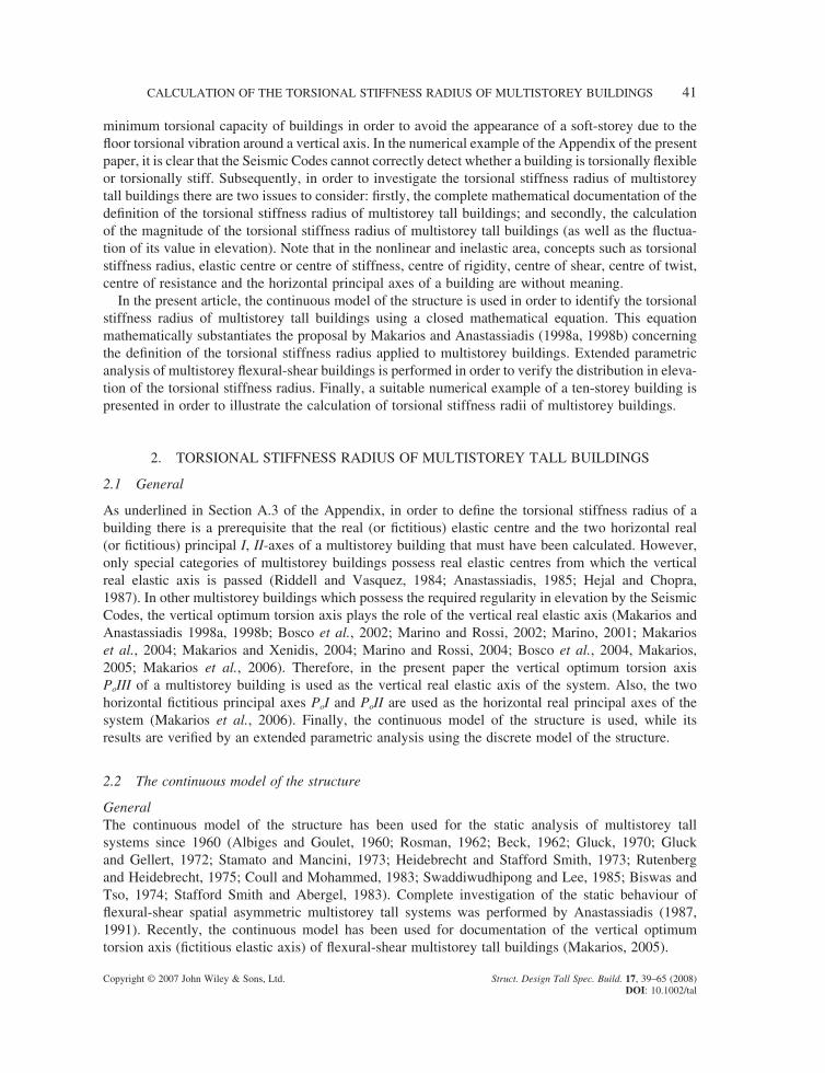
The basic assumptions are the same as those in the Vlassov theory for the calculation of beams of open thin-walled cross-section. Furthermore, for formulation of the continuous model of the structure we assume that the geometric, elastic and mechanical characteristics of the multistorey tall system are constant in elevation. The mathematical model of the system consists of a vertical cantilever that has a constant (in elevation) cross-section with fl exural and shear stiffness. The cross-section is assumed to be a diaphragm (existence of fl oors) and has three degrees of freedom, namely two lateral displacements ux(z), uy(z) along x, y-axes, respectively, and one rotation qz(z) around a vertical axis. According to the continuous model, the fl exural-shear spatial multistorey tall system is separated into two spatial multistorey tall subsystems: the fl exural and the shear, respectively. These two subsystems collaborate with each other (Anastassiadis, 1987, 1991; Makarios, 2005). For the requirements of the present paper, we consider the monosymmetric fl exural-shear multistorey tall building (Figure 1). This comes from the coupling of the spatial fl exural multistorey tall subsystem with the spatial shear multistorey tall subsystem. K and S are the real elastic centres of the two subsystems, respectively, while Ik, IIk are the two horizontal principal axes of the fl exural subsystem and Is, IIs are the two hori-zontal principal axes of the shear subsystem. It has been proven that when the centres K and S of the two subsystems coincide on the same point, then this point is the elastic centre of the whole structure (Anastassiadis, 1987). In all other cases, the vertical optimum torsion III-axis that passes through the fi ctitious elastic centre Po of a plan is always located in the space KS̄ (Makarios, 2005). Also, in the case of the monosymmetric multistorey tall system (Figure 1), the x-axis of symmetry is the real principal I-axis of the whole system and coincides with the Ik, Is-axes of the two subsystems. The second horizontal principal II-axis (fi ctitious) passes through the point Po and is always perpendicular to the I-axis. When the external lateral static loading F(z) belongs to the vertical plane z, II, then the optimum translation of the system along the II-axis (with negligible rotations around a vertical axis) appears (Makarios and Xenidis, 2004; Makarios et al., 2006). Indeed, in the aforementioned paper it has been numerically proved that the degree of freedom uII of all fl oors is uncoupling practically from the two other degrees of freedom (namely, the rotation qz and the other horizontal displacement uI) of the examined level. Therefore, according to the continuous model theory, the equation of the static equilibrium of the multistorey tall system along the II-axis is given by the following differential fourth-order equation (Anastassiadis, 1987; Makarios, 2005):
K u S u F zII II II II′′′′− ′′ = ( ) (1)
Figure 1. Plan of the monosymmetric fl exural–shear multistorey tall system
CALCULATION OF THE TORSIONAL STIFFNESS RADIUS OF MULTISTOREY BUILDINGS 43
Copyright © 2007 John Wiley & Sons, Ltd. Struct. Design Tall Spec. Build. 17, 39–65 (2008) DOI: 10.1002/tal
where KII is the sum of the fl exural stiffness EIi of the sections of the vertical stiffness elements of level i ( K EIII i= ∑ ) along the II-axis; and SII is the sum of the shear stiffness GAs,i of the sections of the vertical stiffness elements of level i ( S GAII S i=∑ , ) along the II-axis.
From this, the torsional stiffness radius of the monosymmetric fl exural multistorey tall system and, separately, the torsional stiffness radius of the monosymmetric shear multistorey tall system are defi ned. As a result, the torsional stiffness radius of the complex coupled monosymmetric fl exural-shear multistorey tall system is also defi ned.
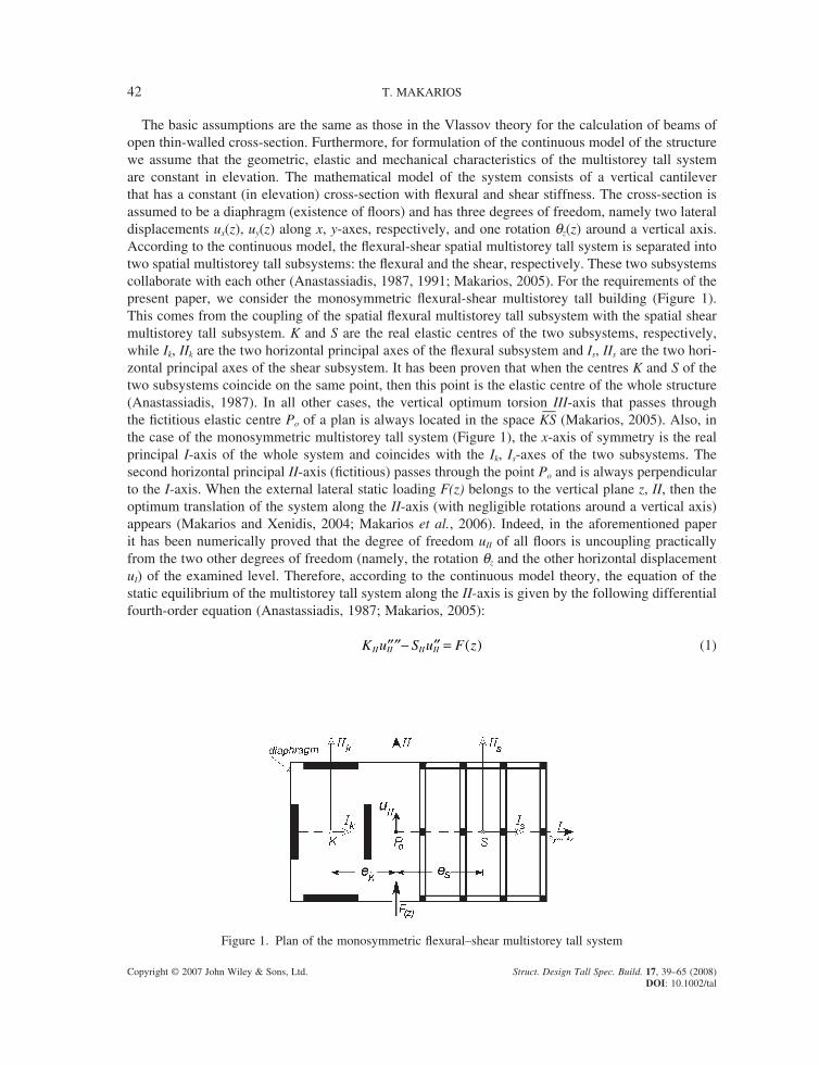
Monosymmetric fl exural multistorey tall buildingsMonosymmetric fl exural multistorey tall buildings belong to the special category that possesses verti-cal real elastic III-axis as well as two horizontal real principal I, II-axes (Figure 2). In order to defi ne the torsional stiffness radius, the following two special loadings must be applied on the monosym-metric fl exural multistorey tall building:
First loading: The horizontal displacement uII (x) of the vertical real elastic III-axis of the level x = z/H in the elevation of the building (where H is the total height of the tall building and z is the distance of level i from the ground) due to the vertical loading plane of the lateral static forces F(z) located on the vertical elastic III-axis, along the II-direction (Figure 2), is calculated from Equation (2) according to the continuous model of the structure (Anastassiadis, 1991):
uM
KH cII
o
II
ξ ξ( ) = × × ( )21 (2)
where M F z zo
H
= ( )∫ d0
is the external fl exural moment (around I-axis) at the base of the tall system due
to static loading F(z); c1(x) is a coeffi cient for the level x = z/H infl uenced by the F(z) distribution; and KII is the translational, along II-axis, fl exural stiffness of the section of the fl exural multistorey tall system.
Second loading: Consider the external loading of the static moments m(z) (around the z-axis) that has the same distribution of forces F(z) in elevation (Figure 2). When the tall building is loaded with the
Figure 2. Plan of the fl exural monosymmetric multistorey tall system
44 T. MAKARIOS
Copyright © 2007 John Wiley & Sons, Ltd. Struct. Design Tall Spec. Build. 17, 39–65 (2008) DOI: 10.1002/tal
loading m(z), then the rotation qIII(x) around the vertical axis of the level x = z/H of the building is cal-culated from Equation (3), according to the continuous model of the structure (Anastassiadis, 1991):
θ ξ ξIIIo
III
B
KH c( ) = × × ( )2
1 (3)
where B M z z m z zo t
o
H
o
H
o
H
= ( ) = ( )∫∫∫ d d 2 is the external bi-moment at the base of the tall system due
to the torsional loading m(z) and KIII is the torsional fl exural stiffness of the section of the fl exural multistorey tall system.
The coeffi cient c1(x) is the same for both of the above loading cases because the distribution of lateral forces F(z) is the same as the distribution of the torsional loading m(z). Therefore, the torsional stiff-ness radius is calculated from the following displacement ratio for each level x = z/H:
u M
B
K
K
u B
MII
III
o
o
III
III
II
III
o
o
ξθ ξ
ρ ξ ξθ ξ
( )( )
= × ⇒ ( ) =( )( )
× (4)
where ρI III IIK K= because KII is the translational stiffness along the II-axis of the section and KIII is the torsional stiffness around a vertical elastic axis of the section of a fl exural multistorey tall system.
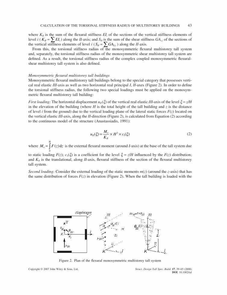
Monosymmetric shear multistorey tall buildingsMonosymmetric shear multistorey tall buildings belong to the special category of buildings that possess real vertical elastic III-axis as well as two horizontal real principal I, II-axes (Figure 3). In order to defi ne the torsional stiffness radius the following two special loadings must be applied on the monosymmetric shear multistorey tall building:
First loading: The horizontal displacement uII(x) of the vertical real elastic III-axis of the level x = z/H in the elevation of the building (where H is the total height of the tall building and z is the distance of the level i from the ground) due to the vertical loading plane of the lateral static forces F(z) that is located on the vertical elastic III-axis along the II-direction (Figure 3) is calculated from Equation (5), according to the continuous model of the structure (Anastassiadis, 1989):
uM
SII
o
II
ξ µ µ ξ( ) = × ( )− ( )[ ]0 (5)
Figure 3. Plan of the shear monosymmetric multistorey tall system
CALCULATION OF THE TORSIONAL STIFFNESS RADIUS OF MULTISTOREY BUILDINGS 45
Copyright © 2007 John Wiley & Sons, Ltd. Struct. Design Tall Spec. Build. 17, 39–65 (2008) DOI: 10.1002/tal
where M F z zo
H
= ( )∫ d0
is the external fl exural moment (around the I-axis) at the base of the tall system
due to static loading F(z); m(0), m(x) are coeffi cients at base (0) and at the level x = z/H respectively in Appendix B of a previous paper by Anastassiadis 1991 (or Makarios, 2005), infl uenced by the distribution of F(z); and SII is the translational, along the II-axis, shear stiffness of the section of the shear multistorey tall system.
Second loading: Consider the external loading of the static moments m(z) (around the z-axis) that has the same distribution with the loading forces F(z) in elevation (Figure 3). When the tall building is loaded with the loading m(z) then the rotation qIII(x) around a vertical axis of the level x = z/H of the building is calculated from Equation (6) according to the continuous model of the structure (Anastassiadis, 1989):
θ ξ µ µ ξIIIo
III
B
S( ) = × ( )− ( )[ ]0 (6)
where B M z z m z zo t
o
H
o
H
o
H
= ( ) = ( )∫ ∫∫d d 2 is the external bi-moment at the base of the tall system due to
the torsional loading m(z).
The coeffi cients m(0)and m(x) are the same in both of the above loading cases because the distribution of the lateral forces F(z) is the same as the distribution of the torsional loading m(z). Therefore, the torsional stiffness radius is calculated from the following displacement ratio for each level x = z/H:
u M
B
S
S
u B
MII
III
o
o
III
III
II
III
o
o
ξθ ξ
ρ ξ ξθ ξ
( )( )
= × ⇒ ( ) =( )( )
× (7)
where ρI III IIS S= because SII is the translational stiffness along the II-axis of the section and SIII is the torsional stiffness around a vertical elastic axis of the section of the shear multistorey tall system.
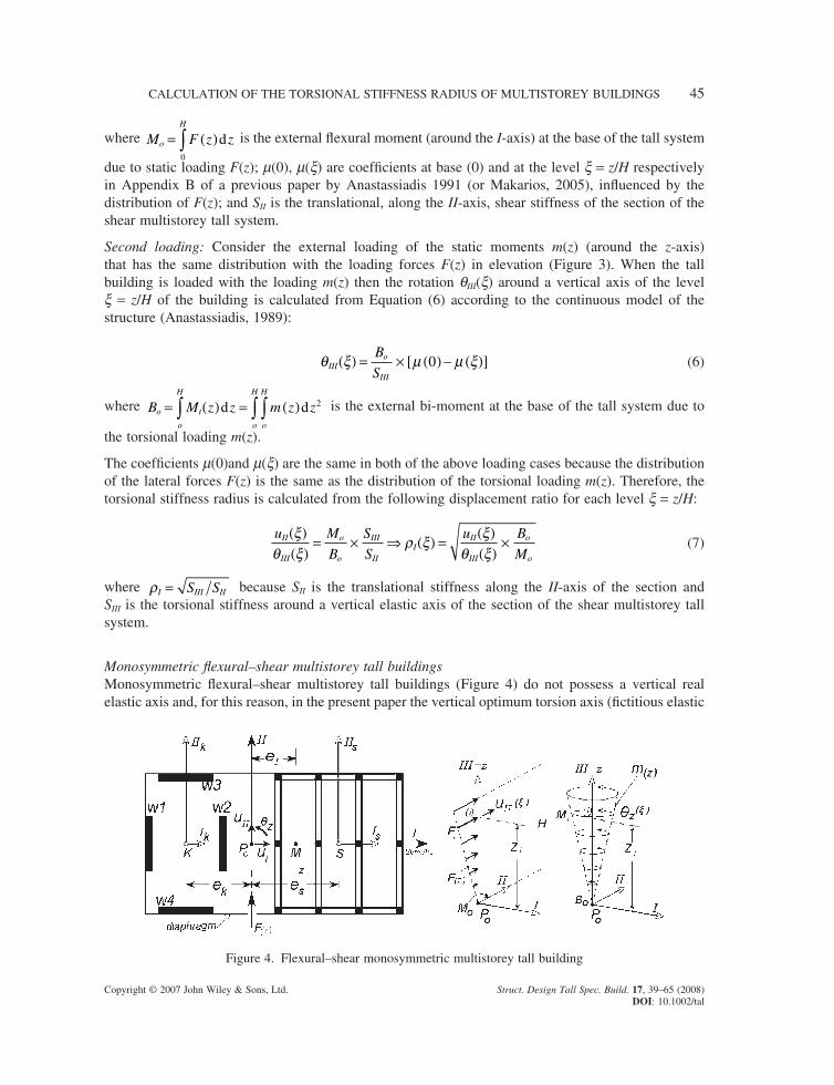
Monosymmetric fl exural–shear multistorey tall buildingsMonosymmetric fl exural–shear multistorey tall buildings (Figure 4) do not possess a vertical real elastic axis and, for this reason, in the present paper the vertical optimum torsion axis (fi ctitious elastic
Figure 4. Flexural–shear monosymmetric multistorey tall building

46 T. MAKARIOS
Copyright © 2007 John Wiley & Sons, Ltd. Struct. Design Tall Spec. Build. 17, 39–65 (2008) DOI: 10.1002/tal
axis) PoIII is used (Makarios and Anastassiadis, 1998a, 1998b; Makarios, 2005; Makarios et al., 2005). The horizontal displacement uII(x) of the optimum torsion axis PoIII, at level x = z/H of a building (where H is the total height of a multistorey tall building and z is the distance from the ground level to level x) due to the vertical loading plane of lateral static forces F(z) that is applied at the optimum torsion axis PoIII along the II-direction is calculated from Equation (8) according to the continuous model of the structure (Anastassiadis, 1989):
uM
SII
o
IIII IIξ µ µ ξ( ) = × ( ) − ( )[ ]0 (8)
where M F z zo
H
= ( )∫ d0
is the external fl exural moment (around I-axis) at the base of the tall system
due to loading F(z); and mII(0) and mII(x) are coeffi cients (Appendix B of Anastassiadis, 1991) of base (0) and of level x = z/H, respectively, suspended from the external static F(z) load distribution as well as from the parameter l × H of the multistorey system along the examined II-direction (Makarios, 2005).
In particular, the parameter l × H is calculated from Equation (1) as follows:
K u S u F z uS
Ku
F z
KII II II II II
II
IIII
II
′′′′− ′′ = ( )⇒ ′′′′− ′′ =( )
(9)
where the positive term SII / KII = l2 has dimensions [L−2]. Parameter l × H does not possess dimension (because H is the total height of the building) and it characterizes the manner of building deforma-tion in elevation (for l × H ≤ 1 there is nearly pure fl exural deformation of the building profi le, for 1 < l × H ≤ 5 there is fl exural–shear deformation of the building profi le, while the fl exural subsystem dominates, for 5 < l × H ≤ 15 there is fl exural–shear deformation of the building profi le, while the shear subsystem dominates, and for 15 < l × H there is nearly pure shear deformation). In addition, consider the external static loading of the moment m(z) around the z-axis (or around the III-axis) that has the same distribution in elevation as the F(z)-loading one. The rotation qz(x) around a vertical axis of level x = z/H, of the building due to the torsional loading m(z) is derived from Equation (10) according to the continuous model of the structure (Anastassiadis, 1991):
θ ξ µ µ ξzo
zzz z
B
S( ) = × ( )− ( )[ ]0 (10)
where B M z z m z zo t
o
H
o
H
o
H
= ( ) = ( )∫ ∫∫d d 2 is the external bi-moment at the base of the tall system due to
the torsional loading m(z); mz(0) and mz(x) are coeffi cients (Appendix B in Anastassiadis, 1991, or Appendix B in Makarios, 2005) of base (0) and of level x = z/H, respectively, suspended from the external static F(z)-loading distribution as well as from the parameter lz × H of the building, where λz zz zzS k= with Szz = SIII + e2
S × SII and Kzz = KIII + e2k × KII are the torsional stiffness coeffi cients of
the shear and the fl exural subsystem, respectively, with reference to the fi ctitious elastic centre Po.Therefore, in absolute correspondence with both of the previous cases of the pure fl exural and the
pure shear multistorey tall buildings, the torsional stiffness radius is now calculated for each level x = z/H by the displacement ratio of Equation (11):
u M S
B S
uII
z
o II II II
o z z zz
IIξθ ξ
µ µ ξµ µ ξ
ξ( )( )
= × ( )− ( )[ ]× ( )− ( )[ ]
⇒(0
0
))( )
= × ( )θ ξ
ρ ξz
o
oI
M
B2 (11)
CALCULATION OF THE TORSIONAL STIFFNESS RADIUS OF MULTISTOREY BUILDINGS 47
Copyright © 2007 John Wiley & Sons, Ltd. Struct. Design Tall Spec. Build. 17, 39–65 (2008) DOI: 10.1002/tal
or ρ ξ ξθ ξI
II
z
o
o
u B
M( ) =
( )( )
× (12)
where ρ ξ ρ µ µ ξµ µ ξI s s
II II
z z
e( ) = +( ) × ( ) − ( )( ) − ( )
2 2 0
0 (13)
and ρs III IIS S= is the torsional stiffness radius of the shear subsystem with reference to its elastic centre S and es is the horizontal distance in the plan from the elastic centre S of the shear subsystem to the trace Po in the plan of the optimum torsion axis of the multistorey tall system (Figure 4). Equation (13) indicates that the torsional stiffness radius rI(x) of the fl exural–shear multistorey tall buildings is not constant in elevation, but is a function of height z. Therefore, when Equation (14) is true for each level x = z/H, then the building is torsionally stiff as it occurs in the case of the single-storey building (see Equation (A.22a, b)):
ρ ξ ρ ξI m I Ie r( ) = + >, ( )2 2 (14)
where eI is the static eccentricity of level x, namely the distance from the fi ctitious elastic centre Po to the mass centre M.
Limits of the torsional stiffness radius rI(x)Equation (13), from which the torsional stiffness radius rI(x) of multistorey tall buildings is calculated, has been parametrically investigated in the present paper using the continuous model of the structure. From this extended parametric analysis, the torsional stiffness radius rI(x) is always located between two limits, which are defi ned by Equation (15):
min , max ,, , , ,ρ ρ ρ ξ ρ ρk P s P I k P s Po o o o{ } ≤ ( ) ≤ { } (15)
where ρ ρk o k kp e, = +2 2 is the torsional stiffness radius of the monosymmetric fl exural multistorey tall subsystem with reference to the vertical optimum torsion axis Po (and ρk III IIK K= is the torsional stiffness radius of the fl exural subsystem around its elastic centre K and ek is the horizontal distance from the fi ctitious elastic centre Po of the multistorey tall building to the elastic centre K of the fl exu-ral tall subsystem, Figure 4); ρ ρs P s so
e, = +2 2 is the torsional stiffness radius of the monosymmetric shear multistorey tall subsystem with reference to the vertical optimum torsion axis Po (where es is the horizontal distance from the fi ctitious elastic centre Po of the multistorey tall building to the elastic centre S of the shear tall subsystem, Figure 4).
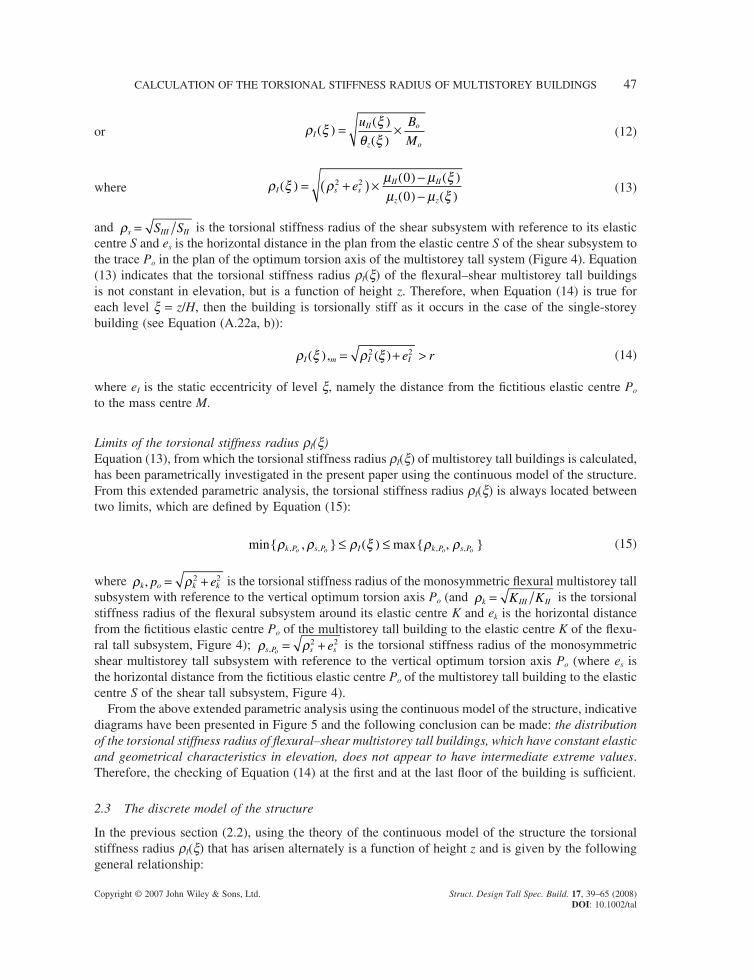
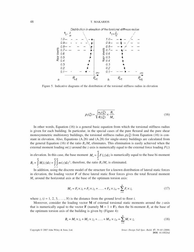
From the above extended parametric analysis using the continuous model of the structure, indicative diagrams have been presented in Figure 5 and the following conclusion can be made: the distribution of the torsional stiffness radius of fl exural–shear multistorey tall buildings, which have constant elastic and geometrical characteristics in elevation, does not appear to have intermediate extreme values. Therefore, the checking of Equation (14) at the fi rst and at the last fl oor of the building is suffi cient.
2.3 The discrete model of the structure
In the previous section (2.2), using the theory of the continuous model of the structure the torsional stiffness radius rI(x) that has arisen alternately is a function of height z and is given by the following general relationship:
48 T. MAKARIOS
Copyright © 2007 John Wiley & Sons, Ltd. Struct. Design Tall Spec. Build. 17, 39–65 (2008) DOI: 10.1002/tal
ρ ξ ξθ ξI
II
z
o
o
u B
M( ) =
( )( )
× (16)
In other words, Equation (16) is a general basic equation from which the torsional stiffness radius is given for each building. In particular, in the special cases of the pure fl exural and the pure shear monosymmetric multistorey buildings, the torsional stiffness radius rI(x) from Equation (16) is con-stant in elevation. Also, Equations (A.26) and (A.28) for single-storey buildings are calculated from the general Equation (16) if the ratio Bo /Mo eliminates. This elimination is easily achieved when the external moment loading m(z) around the z-axis is numerically equal to the external force loading F(z)
in elevation. In this case, the base moment M F z zo
H
= ( )∫ d0
is numerically equal to the base bi-moment
B M z z m z zo t
o
H
o
H
o
H
= ( ) = ( )∫ ∫∫d d 2 ; therefore, the ratio Bo /Mo is eliminated.
In addition, using the discrete model of the structure for a known distribution of lateral static forces in elevation, the loading vector F of these lateral static fl oor forces gives the total fl exural moment Mo around the horizontal axis at the base of the optimum torsion axis:
M F z F z F z F zo N N i ii
N
= × + × + + × = ×=∑1 1 2 2
1
. . . . (17)
where zi (i = 1, 2, 3, . . . , N) is the distance from the ground level to fl oor i.Moreover, consider the loading vector M of external torsional static moments around the z-axis
that is numerically equal to the vector F (namely M = 1 × F), then the bi-moment Bo at the base of the optimum torsion axis of the building is given by (Figure 4):
B M z M z M z M zo N N i ii
N
= × + × + + × = ×=∑1 1 2 2
1
. . . . (18)
Figure 5. Indicative diagrams of the distribution of the torsional stiffness radius in elevation
CALCULATION OF THE TORSIONAL STIFFNESS RADIUS OF MULTISTOREY BUILDINGS 49
Copyright © 2007 John Wiley & Sons, Ltd. Struct. Design Tall Spec. Build. 17, 39–65 (2008) DOI: 10.1002/tal
Therefore, in this case, the ratio Bo /Mo = 1 is true, because
B
M
M z M z M z
F z F z F z
F zo
o
N N
N N
= × + × + + ×× + × + + ×
= ×( ) ×1 1 2 2
1 1 2 2
1 11. . .
. . . ++ ×( ) × + + ×( ) ×
× + × + + ×=1 1
12 2
1 1 2 2
F z F z
F z F z F zN N
N N
. . .
. . .
Consequently, when the ratio Bo /Mo = 1 is true, then the torsional stiffness radius rI(x) of each level x of the fl exural–shear monosymmetric multistorey tall system is given by Equation (19):
ρ ξ ξθ ξI
II
z
u( ) =( )( )
(19)
which is similar to Equations (A.26) and (A.28) for the single-storey building. Hence, Equation (19) mathematically documents the Makarios and Anastassiadis (1998a, 1998b) proposal concerning numerical calculation of the torsional stiffness radius of multistorey buildings.
3. PARAMETRIC ANALYSIS USING THE DISCRETE MODEL OF THE STRUCTURE
For the requirements of the present paper, an extended parametric analysis is performed using the discrete model of the structure, in order to investigate variation of the values of the torsional stiffness radius of buildings regular in elevation. All the monosymmetric fl exural–shear multistorey buildings which have been examined possessed constant geometric and elastic characteristics in elevation and can be divided into four categories with reference to parameter l × H as follows:
(a) multistorey monosymmetric buildings with l × H ≤ 1 that demonstrate nearly pure fl exural deformation in elevation;
(b) multistorey monosymmetric buildings with 1 < l × H ≤ 5 that demonstrate fl exural–shear defor-mation in elevation, while the fl exural multistorey subsystem dominates;
(c) multistorey monosymmetric buildings with 5 < l × H ≤ 15 that demonstrate fl exural–shear deformation in elevation, while the shear multistorey subsystem dominates;
(d) multistorey monosymmetric buildings with 15 < l × H that demonstrate nearly pure shear defor-mation in elevation.
Note that when a multistorey building has l × H < 5, then the second-order phenomena do not appear on the building.
Each monosymmetric multistorey building has been examined for three cases of positions in the plan of its structural walls:
(1) all structural walls have been arranged in the centric third of the plan of the buildings in order for the last to be torsionally fl exible;
(2) the structural walls have been arranged uniformly in the plan of the buildings;(3) the structural walls have been located (in pairs) near or on the perimeter of the buildings in order
for the last to be torsionally stiff.
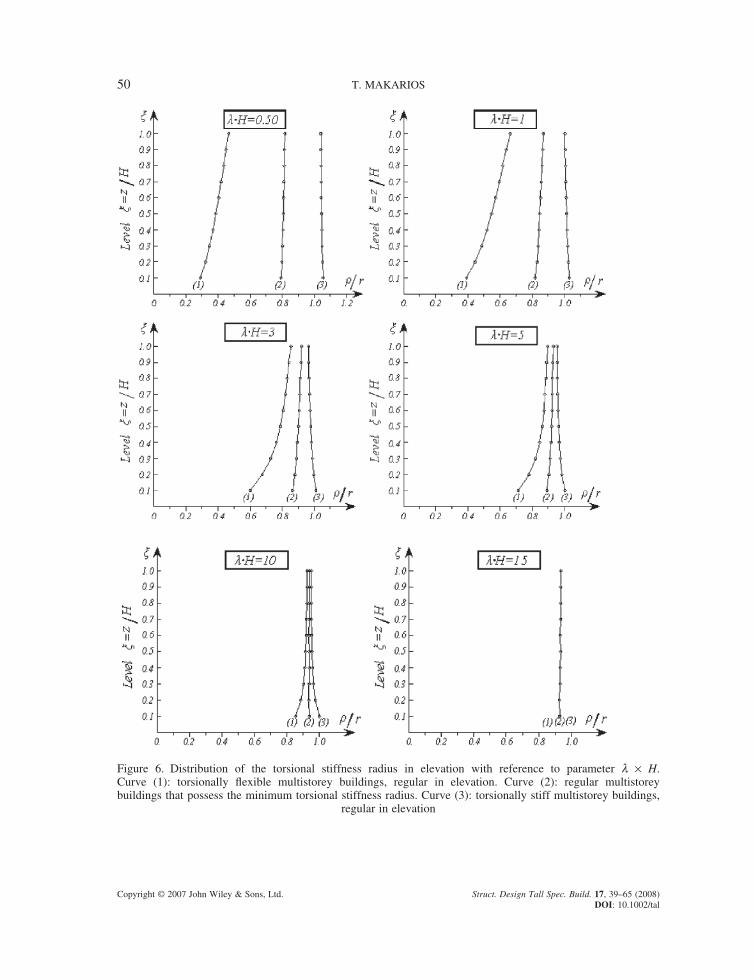
In Figure 6, we can identify several indicative results of the parametric analysis, where the torsional stiffness radius r(x) is given as a percentage of the radius of gyration r J m= of the diaphragm. From Figure 6 the following conclusions can be made:
(i) The distribution of the torsional stiffness radius of regular multistorey buildings does not dem-onstrate extreme intermediate values.
(ii) When multistorey buildings possess l × H ≥ 5, then the arrangement of the structural walls in the plan barely affects the torsional stiffness radius r(x) of the building. In these buildings, the
50 T. MAKARIOS
Copyright © 2007 John Wiley & Sons, Ltd. Struct. Design Tall Spec. Build. 17, 39–65 (2008) DOI: 10.1002/tal
Figure 6. Distribution of the torsional stiffness radius in elevation with reference to parameter l × H. Curve (1): torsionally fl exible multistorey buildings, regular in elevation. Curve (2): regular multistorey buildings that possess the minimum torsional stiffness radius. Curve (3): torsionally stiff multistorey buildings,
regular in elevation
CALCULATION OF THE TORSIONAL STIFFNESS RADIUS OF MULTISTOREY BUILDINGS 51
Copyright © 2007 John Wiley & Sons, Ltd. Struct. Design Tall Spec. Build. 17, 39–65 (2008) DOI: 10.1002/tal
torsional stiffness radius is mainly affected by the arrangement of the planar multistorey shear frames.
(iii) When multistorey buildings possess l × H < 5, then the arrangement of the structural walls in the plan signifi cantly affects the torsional stiffness radius r(x) of the building (see curves 1, 2 and 3) of Figure 6.
(iv) When in a building (with l × H < 5) the structural walls are located in the plan with a uniform arrangement, then the building is usually characterized as torsionally fl exible (curve 2).
(v) When 80% of fl exural stiffness EI of sections of the structural walls is located in pairs on the perimeter of a building (which has l × H < 5), then this building usually has the minimum torsional stiffness (curve 3).
(vi) In torsionally fl exible buildings with l × H < 5 (curves 1 and 2), the fi rst fl oors of the system have a smaller torsional stiffness radius r(x) than that of other fl oors. Therefore, in a torsionally fl exible building that is regular in elevation, checking of Equation (14) must be performed for the fi rst level only.
(vii) For each type of multistorey tall building which possesses the required regularity in elevation by the Seismic Codes, checking of Equation (14) must be performed for the fi rst and last fl oors of the building as well as for level where there is strong variation of fl exural stiffness of the sections of the structural walls.
(viii) Finally, the scattering of the torsional stiffness radius of torsionally stiff fl exural–shear multi-storey tall buildings regular in elevation (curve 3) is not important. Therefore, for simplicity reasons we can take a mean value of the torsional stiffness radius and this value can be con-sidered nearly constant for the whole building (i.e., the torsional stiffness radius r(0·8) of the level x = 0·80 or the numerical/geometric mean term of the torsional stiffness radius of all the fl oors of a building).
4. NUMERICAL EXAMPLE OF A FLEXURAL–SHEAR TEN-STOREY BUILDING
4.1 General
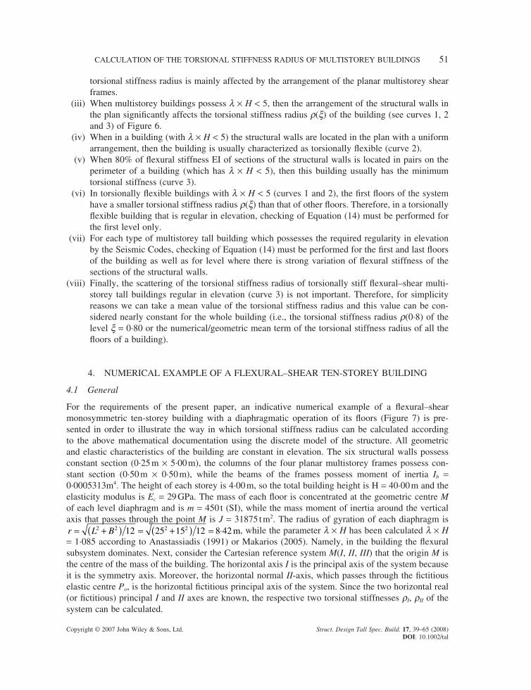
For the requirements of the present paper, an indicative numerical example of a fl exural–shear monosymmetric ten-storey building with a diaphragmatic operation of its fl oors (Figure 7) is pre-sented in order to illustrate the way in which torsional stiffness radius can be calculated according to the above mathematical documentation using the discrete model of the structure. All geometric and elastic characteristics of the building are constant in elevation. The six structural walls possess constant section (0·25 m × 5·00 m), the columns of the four planar multistorey frames possess con-stant section (0·50 m × 0·50 m), while the beams of the frames possess moment of inertia Ib = 0·0005313m4. The height of each storey is 4·00 m, so the total building height is H = 40·00 m and the elasticity modulus is Ec = 29 GPa. The mass of each fl oor is concentrated at the geometric centre M of each level diaphragm and is m = 450 t (SI), while the mass moment of inertia around the vertical axis that passes through the point M is J = 31875 t m2. The radius of gyration of each diaphragm is r L B= +( ) = +( ) = ⋅2 2 2 212 25 15 12 8 42 m, while the parameter l × H has been calculated l × H = 1·085 according to Anastassiadis (1991) or Makarios (2005). Namely, in the building the fl exural subsystem dominates. Next, consider the Cartesian reference system M(I, II, III) that the origin M is the centre of the mass of the building. The horizontal axis I is the principal axis of the system because it is the symmetry axis. Moreover, the horizontal normal II-axis, which passes through the fi ctitious elastic centre Po, is the horizontal fi ctitious principal axis of the system. Since the two horizontal real (or fi ctitious) principal I and II axes are known, the respective two torsional stiffnesses rI, rII of the system can be calculated.
52 T. MAKARIOS
Copyright © 2007 John Wiley & Sons, Ltd. Struct. Design Tall Spec. Build. 17, 39–65 (2008) DOI: 10.1002/tal
4.2 Loading vector M of static torsional moments
Consider the loading vector M of the external fl oor static moments around the III (or z)-axis that is numerically equal to the loading F of the lateral static fl oor forces (the base shear is considered as 10 000 kN and M and F are applied as shown in Figure 4), while both vectors possess triangular dis-tribution in elevation (namely M = 1 × F). The ratio Bo/Mo = 1 arises. The displacements ux8, uy8, qz8 of the origin M at the level zo = 0·8H due to loading vector M have been calculated as follows:
ux8 0 muy8 −0·003435 mqz8 0·001827 rad
The vertical optimum torsion axis passes through the pole of rotation Po (XP, YP) of the level zo = 0·8H:
Xu
Yu
Py
zP
x
z
= − = − − ⋅+ ⋅
= + ⋅ = =+ ⋅
=8
8
8
8
0 003435
0 0018271 88
0
0 001827θ θ, 00
Therefore, the static eccentricity is eI = 1·88 m or eI = 0·0755 × L (Figure 7).
4.3 Calculation of the torsional stiffness radius rI of the multistorey building
The horizontal displacements uII,F of the building due to loading vector F which is located on the verti-cal optimum torsion axis along the II-axis as well as the fl oor rotations qz,M around a vertical axis due
Figure 7. Plan of ten-storey monosymmetric building
CALCULATION OF THE TORSIONAL STIFFNESS RADIUS OF MULTISTOREY BUILDINGS 53
Copyright © 2007 John Wiley & Sons, Ltd. Struct. Design Tall Spec. Build. 17, 39–65 (2008) DOI: 10.1002/tal
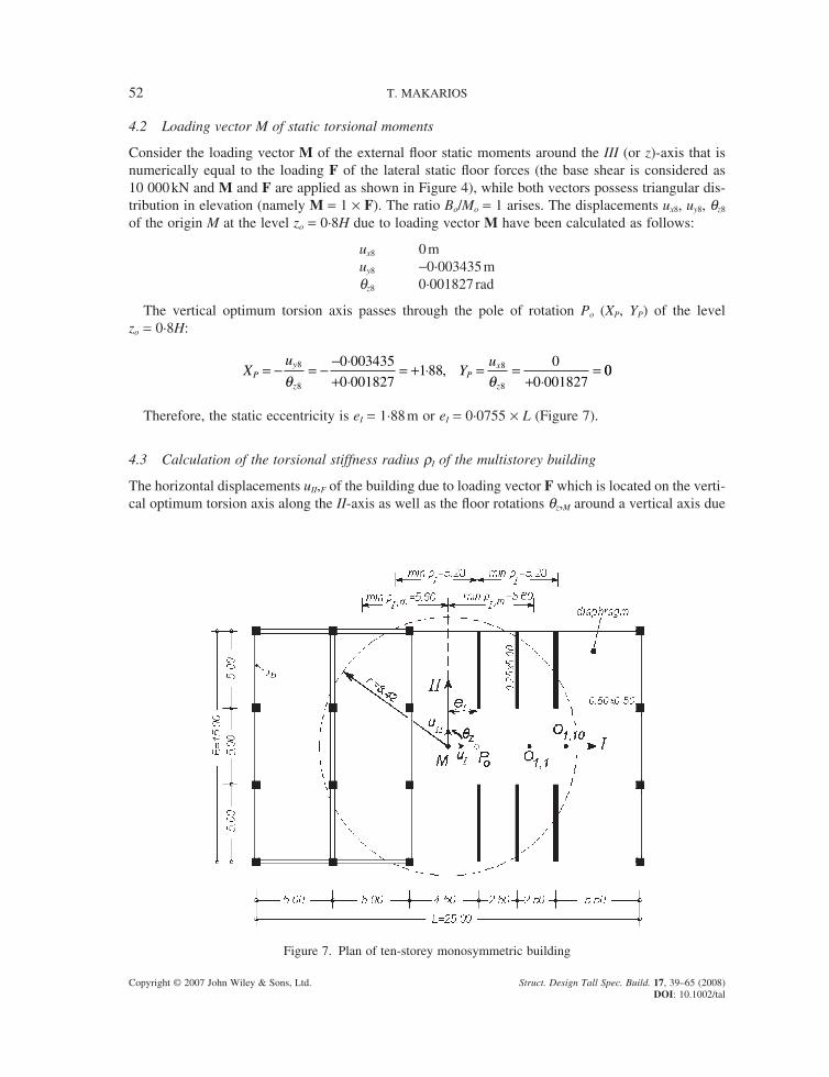
to loading vector M are shown in Table 1. In addition, the torsional stiffness radii rI(x) for each level x of the building are calculated from Equation (19) because the ratio Bo/Mo = 1 is true. Note that the same values of the torsional stiffness radii arise following Tso and Moghadam’s (1998) procedure.
In Table 1, we can see that the least torsional stiffness radius of the building appears at the fi rst level. Therefore, the torsional stiffness radius with reference to mass centre M of the building is given by Equation (A.22a):
min min, ρ ρI M I Ie= ( ) + = ⋅ + ⋅ = ⋅2 2 2 25 28 188 5 60 m
Therefore, according to Equation (14), the building is characterized as torsionally fl exible because
min , ρI M r= ⋅ < = ⋅5 60 8 42m m
This fact is verifi ed by modal analysis because in the fi rst coupled mode shape the poles O1,i of vibration of all fl oors (i is the fl oor level) are located in the circle that has as its radius the radius of gyration of the diaphragm. Note that in the fi rst coupled mode shape of this ten-storey building the poles of vibration of all fl oors are located between the pole of vibration O1,1 of the fi rst fl oor and the pole of vibration O1,10 of the tenth fl oor (Figure 7).
5. CONCLUSIONS
In the present paper, the issue of the defi nition and calculation of the torsional stiffness radius of mul-tistorey tall buildings has been documented and discussed. Using the theory of the continuous model of the structure, the torsional stiffness radius of monosymmetric multistorey tall buildings has been given by a closed mathematical equation (see Equation (13)). Similarly, for monosymmetric multi-storey tall buildings the torsional stiffness radius has been given by Equation (12) or (16), which has been readily used for both the continuous and the discrete model of the structure. The defi nition of the torsional stiffness radius (Equations (A.26) and A.(28)) of single-storey buildings has been calculated as a special case in Equation (16). The torsional stiffness radius of multistorey tall buildings has had a variable value in elevation. In particular, for multistorey buildings the following conclusions can be made:
Table 1. Calculation of torsional stiffness radii rI(x) for each level (x = z/H)
Levels (x) uII,F qz,M rI(x) h ́ rI(x)
1·0 0·14124 0·00211 8·18 h ́ 0·97 r0·9 0·12463 0·00198 7·93 h ́ 0·94 r0·8 0·10757 0·00183 7·67 h ́ 0·91 r0·7 0·09018 0·00164 7·42 h ́ 0·88 r0·6 0·07271 0·00141 7·18 h ́ 0·85 r0·5 0·05559 0·00117 6·89 h ́ 0·82 r0·4 0·03938 0·0009043 6·60 h ́ 0·78 r0·3 0·02476 0·000633 6·25 h ́ 0·74 r0·2 0·01259 0·0003693 5·84 h ́ 0·69 r0·1 0·00388 0·0001390 5·28 h ́ 0·63 r
54 T. MAKARIOS
Copyright © 2007 John Wiley & Sons, Ltd. Struct. Design Tall Spec. Build. 17, 39–65 (2008) DOI: 10.1002/tal
(1) The distribution of the torsional stiffness radius of regular multistorey buildings does not appear to have extreme intermediate values.
(2) The scattering of torsional stiffness radius of torsionally stiff fl exural–shear multistorey tall build-ings is not important. Therefore, for reasons of simplicity in the frame of the ‘equivalent static method’, we can take a mean value of the torsional stiffness radius, constant for the whole building (i.e., the torsional stiffness radius r(0·8) of the level x = 0·80 or the numerical/geometric mean term of the torsional stiffness radius of all fl oors of the building).
(3) For each multistorey tall building, Equation (14) must be checked for the fi rst and last fl oors of the building as well as for that level where there is strong variation in the fl exural stiffness of sections of the structural walls.
(4) Each multistorey building must possess the minimum torsional stiffness radius defi ned by Equa-tion (14) in order to avoid torsional fl exibility of the building.
REFERENCES
Albiges M, Goulet J. 1960. Contreventement des batiments. Annales de l’ITBTP, Ser. TMC/38, No. 149.Anastassiadis K. 1985. Caracteristiques elastiques spatiales des batiments a etages. Annales de l’ITBTP, June,
No. 435.Anastassiadis K. 1987. Analyse statique tridimensionnelle du contreventement des batiments: la method des trois
pivots. Annales de I’ITBTP, No. 452.Anastassiadis K. 1989. Antiseismic Structures I. Computer Technics: Thessaloniki, Greece (in Greek).Anastassiadis K. 1991. Calcul Statique des contreventements par la method des trois pivots: theorie et applica-
tions. Annales de I’ITBTP, No. 498.Anastassiadis K, Athanatopoulou A, Makarios T.1998. Equivalent static eccentricities in the simplifi ed methods
of seismic analysis of buildings. Earthquake Spectra 14(1): 1–34.Beck H. 1962. Contribution to the analysis of coupled shear walls. Journal of the ACI 59(8): 1055–1070.Biswas J, Tso W. 1974. Three-dimensional analysis of shear wall buildings to lateral load. Journal of the Structural
Division, ASCE 100(ST5): 1019–1036.Bosco M, Ghersi A, Marino E, Rossi P. 2002. Effects of in-elevation irregularity on the elastic seismic response
of in-plan asymmetric buildings. In Proceedings of the 3rd European Workshop on the Seismic Behaviour of Irregular and Complex Structures, European Association for Earthquake Engineering, Florence, Italy.
Bosco M, Marino E, Rossi P. 2004. Limits of application of simplifi ed design procedures to non-regularly asym-metric buildings. In 13th World Conference on Earthquake Engineering, Vancouver, BC, Canada, 1–6 August, Paper No. 886.
Calderoni B, D’Aveni A, Ghersi A, Rinaldi Z. 2002. Static vs. modal analysis of asymmetric buildings: effective-ness of dynamic eccentricity formulations. Earthquake Spectra 18(2): 219–231.
Chandler AM, Hutchinson GL. 1988. Evaluation of the secondary torsional design provisions of earthquake build-ing codes. In Proceedings of Institution of Civil Engineers, Part 2, December; 587–607.
Coull A, Mohammed T. 1983. Simplifi ed analysis of lateral load distribution in structures consisting of frames, coupled shear walls and cores. Structural Engineer 61B(1): 1–8.
Dempsey KM, Irvine HM. 1979. Envelopes of maximum seismic response for a partially symmetric single storey building model. Earthquake Engineering and Structural Dynamics 7: 161–180.
Dempsey KM, Tso WK. 1982. An alternative path to seismic torsional provisions. Soil Dynamics and Earthquake Engineering 1(1): 3–11.
Gluck J. 1970. Lateral-load analysis of asymmetric multistorey structures. Journal of the Structural Division, ASCE 96(ST2): 317–327.
Gluck J, Gellert M. 1972. Three-dimensional load analysis of multistorey structures. Memoires de l’AIPC 32(1): 77–90.
Heidebrecht A, Stafford Smith B. 1973. Approximate analysis of tall wall-frame structures. Journal of the Struc-tural Division, ASCE 99(ST2): 199–221.
Hejal R, Chopra AK. 1987. Earthquake response of torsionally-coupled buildings. Report No UCB/e.e.r.c.-87/20, University of California, Berkeley, CA.
Makarios T. 2005. Optimum torsion axis to multistorey buildings by using the continuous model of the structure. Structural Design of Tall and Special Buildings 14: 69–90.
CALCULATION OF THE TORSIONAL STIFFNESS RADIUS OF MULTISTOREY BUILDINGS 55
Copyright © 2007 John Wiley & Sons, Ltd. Struct. Design Tall Spec. Build. 17, 39–65 (2008) DOI: 10.1002/tal
Makarios T, Anastassiadis K. 1998a. Real and fi ctitious elastic axis of multi-storey buildings: theory. Structural Design of Tall Buildings 7: 33–55.
Makarios T, Anastassiadis K. 1998b. Real and fi ctitious elastic axis of multi-storey buildings: applications. Struc-tural Design of Tall Buildings 7: 57–71.
Makarios T, Xenidis H. 2004. Optimum translational vibration of multi-storey buildings with vertical mass axis. In Proceedings of the International Conference on Computational and Experimental Engineering and Sciences (ICCES ’04), Madeira, Portugal, 26–29 July; 687–692.
Makarios T, Xenidis H, Karakostas C, Lekidis V. 2004. Verifying the location of the optimum torsion axis of multi-storey buildings using dynamic analysis. In Proceedings of the 13th World Conference on Earthquake Engineering, Vancouver, BC Canada, 1–6 August, paper 833.
Makarios T, Athanatopoulou AM, Xenidis H. 2006. Numerical verifi cation of properties of the fi ctitious elastic axis in asymmetric multistorey buildings. Structural Design of Tall and Special Buildings 15: 249–276.
Marino E. 2001. Analisi critica della defi nizione di edifi ci regolarmente asimmetrici. In Proceedings of the 10th National Conference ‘L’ingegneria sismica in Italia, Potenza-Matera, Italy, 9–13 September (in Italian).
Marino E, Rossi PP. 2002. Analytical formulation of the optimum torsion axis. In Proceedings of the 3rd European Workshop on the Seismic Behaviour of Irregular and Complex Structures, European Association for Earthquake Engineering, Florence, Italy.
Marino E, Rossi PP. 2004. Exact evaluation of the location of the optimum torsion axis. Structural Design of Tall and Special Buildings 13(4): 277–290.
Riddell R, Vasquez J. 1984. Existence of centres of resistance and torsional uncoupling of earthquake response of buildings. In Proceedings of the 8th World Conference on Earthquake Engineering, Vol. 4; 187–194.
Rosman R. 1960. Beitrig Zur statischen Berechnung waagrecht belasteter Querwande bei Hochbauten. Der Bauingenieur, Heft 4.
Rosman R. 1962. Beitrag zur statischen Berechnung waagrecht belasteter Querwande bei Hochbauten. Der Bauingenieur Heft 1.
Roussopoulos A. 1932. Distribution of horizontal forces by a rigid plate in spatial structures: case of seismic forces, their distribution and regime. Technika Chronika, No. 17, September 1932, Technical Chamber of Greece; 871–884 (in Greek).
Rutenberg A, Heidebrecht A. 1975. Approximate analysis of asymmetric wall-frame structures. Building and Environment 10: 27–35.
Rutenberg A, Pekau OA. 1987. Seismic code provisions for asymmetric structures: a re-evaluation. Engineering Structures 9: 255–264.
Stafford Smith B, Abergel D. 1983. Approximate analysis of high-rise structures comprising coupled walls and shear walls. Building and Environment 18(1/2): 91–96.
Stamato M, Mancini E. 1973. Three-dimensional interaction of walls and frames. Journal of the Structural Divi-sion, ASCE 99(ST12): 2375–2390.
Swaddiwudhipong S, Lee L. 1985. Core-frame interaction in tall buildings. Engineering Structures 7: 51–55.Tso WK, Dempsey KM. 1980. Seismic torsional provisions for dynamic eccentricity. Earthquake Engineering
and Structural Dynamics 8: 275–289.Tso WK, Moghadam AS. 1998. Application of Eurocode 8 torsional provisions to multi-storey buildings. In 11th
European Conference on Earthquake Engineering, September, Paris (on CD).Tso WK, Wong CM.1995. Eurocode 8 seismic torsional provisions evaluation. Journal of European Earthquake
Engineering 1: 23–33.
APPENDIX A: THE TWO TORSIONAL STIFFNESS RADII OF A SINGLE-STOREY BUILDING
A.1 The asymmetric single-storey building
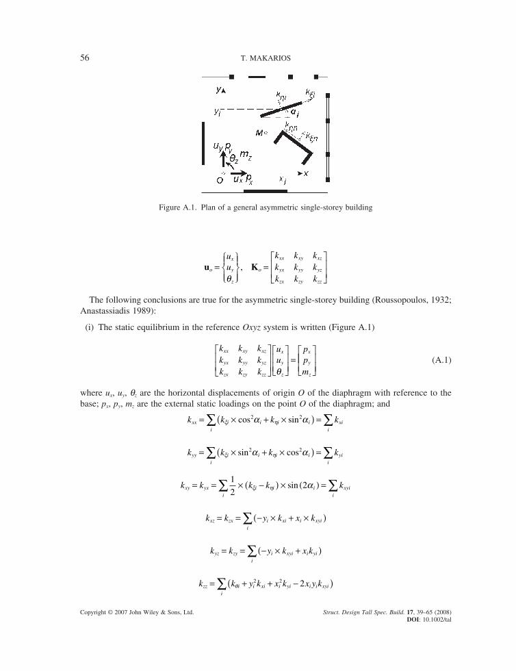
Consider the asymmetric single-storey building consisting of a rigid deck (with diaphragmatic opera-tion around a vertical axis) supported on mass-less planar frames, structural walls and cores and referring to the global Cartesian system Oxyz (Figure A.1). The origin O(0,0) of the diaphragm has three degrees of freedom; two horizontal displacements ux and uy along the respective horizontal x, y-axes and a rotation qz around a vertical z-axis. The vector of displacements uo and the lateral stiffness matrix Ko of the building with reference to the Oxyz system are given by
56 T. MAKARIOS
Copyright © 2007 John Wiley & Sons, Ltd. Struct. Design Tall Spec. Build. 17, 39–65 (2008) DOI: 10.1002/tal
u Ko
x
y
z
o
xx xy xz
yx yy yz
zx zy zz
uu
k k kk k kk k k
=
=
θ
,
The following conclusions are true for the asymmetric single-storey building (Roussopoulos, 1932; Anastassiadis 1989):
(i) The static equilibrium in the reference Oxyz system is written (Figure A.1)
k k kk k kk k k
uu
ppm
xx xy xz
yx yy yz
zx zy zz
x
y
z
x
y
z
=
θ
(A.1)
where ux, uy, qz are the horizontal displacements of origin O of the diaphragm with reference to the base; px, py, mz are the external static loadings on the point O of the diaphragm; and
k k k kxx i i i ii
xii
= × + ×( ) =∑ ∑ξ ηα αcos sin2 2
k k k kyy i i i ii
yii
= × + ×( ) =∑ ∑ξ ηα αsin cos2 2
k k k k kxy yx i i ii
xyii
= = × −( ) × ( ) =∑ ∑1
22ξ η αsin
k k y k x kxz zx i xi i xyii
= = − × + ×( )∑
k k y k x kyz zy i xyi i yii
= = − × +( )∑
k k y k x k x y kzz i i xi i yi i i xyii
= + + −( )∑ θ2 2 2
Figure A.1. Plan of a general asymmetric single-storey building
CALCULATION OF THE TORSIONAL STIFFNESS RADIUS OF MULTISTOREY BUILDINGS 57
Copyright © 2007 John Wiley & Sons, Ltd. Struct. Design Tall Spec. Build. 17, 39–65 (2008) DOI: 10.1002/tal
with ai being the orientation angle of the structural element i in the reference x-axis of the global Oxyz system. (ii) The special reference system K(I, II, III), where the lateral stiffness matrix is diagonal, can always
be defi ned as follows (Figure A.2):
k
kk
uu
ppm
I
II
III
I
II
z
I
II
k
0 00 00 0
=
θ (A.2)
where uk is the vector of degrees of freedom and Kk is the lateral stiffness matrix of a single-storey building in the special reference system K(I, II, III).
u Kk
I
II
z
k
I
II
III
uu
kk
k=
=
θ
,0 0
0 00 0
(A.3)
k kk k k k
kI IIxx yy xx yy
xy, =+
±−
+
2 2
22 (A.4)
k k x k y k x y k x k y kIII zz k yy k xx k k xy k yz k xz= + + − − +2 2 2 2 2 (A.5)
The coordinates (xk, yk) of the origin K and the oriented angle wk of the horizontal principal I, II-axes of a single-storey building can be calculated from Equations (A.6a–c) (Figure A.2):
xk k k k
k k ky
k k k k
k k kk
xx zy xy zx
xx yy xyk
yy zx yx zy
xx yy xy
=−−
= −−−2 2
, , taan 22
ωkxy
xx yy
k
k k( ) =
−
(A.6a, b, c)
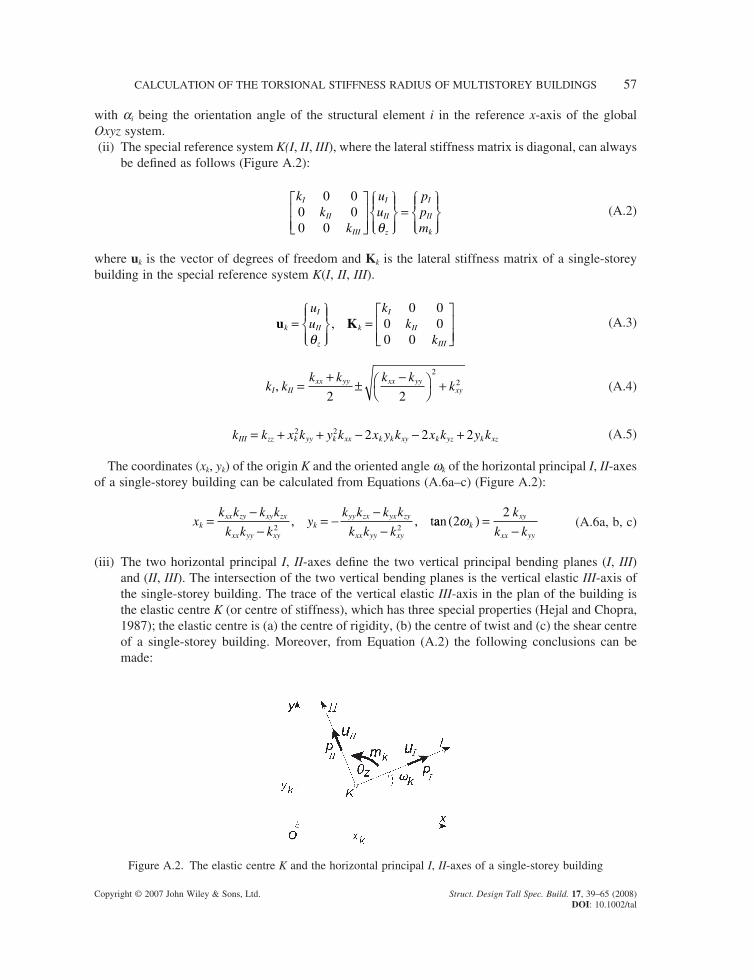
(iii) The two horizontal principal I, II-axes defi ne the two vertical principal bending planes (I, III) and (II, III). The intersection of the two vertical bending planes is the vertical elastic III-axis of the single-storey building. The trace of the vertical elastic III-axis in the plan of the building is the elastic centre K (or centre of stiffness), which has three special properties (Hejal and Chopra, 1987); the elastic centre is (a) the centre of rigidity, (b) the centre of twist and (c) the shear centre of a single-storey building. Moreover, from Equation (A.2) the following conclusions can be made:
Figure A.2. The elastic centre K and the horizontal principal I, II-axes of a single-storey building
58 T. MAKARIOS
Copyright © 2007 John Wiley & Sons, Ltd. Struct. Design Tall Spec. Build. 17, 39–65 (2008) DOI: 10.1002/tal
• When the lateral static force P is observed on the elastic centre K along the principal axes I or II (namely, forces pI or pII), then the diaphragm of the building is translated along the principal I or II-axis, respectively, without rotation.
• When the lateral static force P is located on the elastic centre K with an orientation different from that of the principal I or II-axis, then the diaphragm of the building is translated along the other orientation from that of the loading P without rotation. The end of the displacement vector of the elastic centre is located on the periphery of an ellipse, which has Equation (A.7) with fI = 1/kI and fII = 1/kII being the lateral fl exibilities of the single-storey building (Anastassiadis 1989):
u
f
u
fPI
I
II
II
2
2
2
22+ = (A.7)
• The external torsional moment loading mk causes rotation around the III-axis that passes through the elastic centre K of the building.
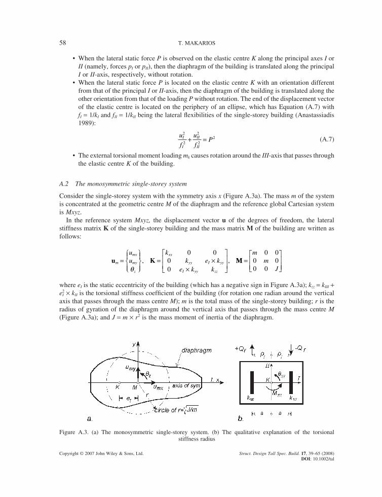
A.2 The monosymmetric single-storey system
Consider the single-storey system with the symmetry axis x (Figure A.3a). The mass m of the system is concentrated at the geometric centre M of the diaphragm and the reference global Cartesian system is Mxyz.
In the reference system Mxyz, the displacement vector u of the degrees of freedom, the lateral stiffness matrix K of the single-storey building and the mass matrix M of the building are written as follows:
u Km
mx
my
z
xx
yy I yy
I yy zz
uu
kk e k
e k k=
= ×
×
θ
, ,0 0
00
MM =
mm
J
0 00 00 0
where eI is the static eccentricity of the building (which has a negative sign in Figure A.3a); kzz = kIII + e2
I × kII is the torsional stiffness coeffi cient of the building (for rotation one radian around the vertical axis that passes through the mass centre M); m is the total mass of the single-storey building; r is the radius of gyration of the diaphragm around the vertical axis that passes through the mass centre M (Figure A.3a); and J = m × r2 is the mass moment of inertia of the diaphragm.
Figure A.3. (a) The monosymmetric single-storey system. (b) The qualitative explanation of the torsional stiffness radius
CALCULATION OF THE TORSIONAL STIFFNESS RADIUS OF MULTISTOREY BUILDINGS 59
Copyright © 2007 John Wiley & Sons, Ltd. Struct. Design Tall Spec. Build. 17, 39–65 (2008) DOI: 10.1002/tal
Next, the eigenvalue problem of the single-storey building is written as
K M 0−( ) =ω 2 j (A.8)
where w is the unknown frequency, j = {jx jy jz}T is the unknown mode shape and 0 is the three-dimensional null vector.
For the calculation of eigenvalues w21, w2
2, w23 from the eigenvalue problem of Equation (A.8), we
nullify the determinant det|K − w2M| = 0. Due to the symmetry x-axis, the eigenvalue problem of Equation (A.8) is divided into two independent equations:
k mxx x− ×( ) × =ω ϕ2 0 (A.9a)
k m e k
e k k Jyy I yy
I yy zz
y
z
− × ×× − ×
{ } = { }ω
ωϕϕ
2
2
00
(A.9b)
kxx − w2 × m = 0 is derived in Equation (A.9a), so the translational frequency along the symmetry x-axis is given (the symmetry x-axis is simultaneously the principal axis I of the building):
ω ωx xx I Ik m k m= = = (A.10)
The mode shape of Equation (A.9a) is uncoupled from the other two; therefore, the vibration of the single-storey building along the x-axis is purely translational. The other two eigenvalues w2
2, w23 are
derived from the solution of the following quadratic equation:
ω ω ω ω ω ωω4 2 2 2 2 2
2 2
20− × +( ) + × −
×
=y z y z
I ye
r (A.11)
where
ω ωy yy II IIk m k m= = = (A.12a)
ω ω ωz zz III I II III
I IIk J k e k m re
r= = + ×( ) ( ) = + ×2 2 2
2 2
2 (A.12b)
from which the two w21 and w2
2 are given:
ω ω λ λ1 22 2
2 2 2 2
2
1
2
1
2, =
+ −
+
y
x x Ie
r∓ (A.13)
where
λ ωω
ρx
z
y
zz
II
zz II III I II II I Ik J
k m
k k
r
k e k k
r
e
r= = = = + ×( ) = +2 2 2
(A.14)
and ρI III IIk k= is the torsional stiffness radius of the building with reference to the elastic centre K.
60 T. MAKARIOS
Copyright © 2007 John Wiley & Sons, Ltd. Struct. Design Tall Spec. Build. 17, 39–65 (2008) DOI: 10.1002/tal
As proven in Appendix A of the paper by Anastassiadis et al. (1998), in a torsionally fl exible build-ing, namely, in a building where the fundamental mode shape has a torsional character, it is always true that wz/wy < 1 and according to Equation (A.14) this means that the torsional fl exibility of a building depends on the magnitude of the torsional stiffness radius:
ρI Ie r2 2+ < (A.15)
The term ρI Ie2 2+ gives the torsional stiffness radius rI,M of the building with reference to the centre mass M.
Consequently, in order to qualitatively comprehend the torsional stiffness radius we consider the monosymmetric single-storey system, which consists of two similar structural walls, located in parallel, each one of which has a lateral translational stiffness kw, while the system possesses a diaphragmatic operation on the fl oor level, as shown in Figure (A.3b). These walls are oriented along the principal II-axis at a distance a from the elastic centre K of the system. When this system is loaded with the static moment MIII around the vertical III-axis, then the rotation of the diaphragm is qIII = MIII/kIII and the shear forces of restoration of the system are +Qr, −Qr, which are applied on the structural walls. The lateral stiffness kII of the system is kII = 2 kw and the torsional stiffness kIII of the system with reference to the elastic centre K is calculated:
k k a k a k a k a a k k aIII w w w II III II I= × + × = × × = × ⇒ = ⇒ =2 2 2 22 ρ (A.16)
Therefore, the level-arm a from the elastic centre K to each structural wall is equal to the torsional stiffness radius of the monosymmetric single-storey system. Hence, the torsional stiffness radius rI is the level-arm with reference to the elastic centre K along the principal I-axis of elastic lateral forces of restoration due to external pure torsional loading MIII (Figure A.3b).
Moreover, in the case of a monosymmetric single-storey building, where the two coupled fre-quencies w1 & w2 are known from Equation (A.13), the three mode shapes are given by Equations (A.17a–c):
j1 1 1 1 1 10= { } = { }ϕ ϕ ϕ ϕ ϕx y zT
y zT (A.17a)
j2 2 2 2 2 20= { } = { }ϕ ϕ ϕ ϕ ϕx y zT
y zT (A.17b)
j3 3 3 3 1 0 0= { } = { }ϕ ϕ ϕx y zT T (A.17c)
where
ϕω ω
ϕyI
yz
e1
12 2 1
11 00= −
−= ⋅and (A.18a, b)
ϕω ω
ϕyI
yz
e2
22 2 2
11 00= −
−= ⋅and (A.19a, b)
Note that the order of the mode shapes is defi ned by the order of the frequencies of the system. Also, in the general case of an asymmetric single-storey building, the coordinates exi, eyi of the pole Oi(exi, eyi) of vibration for the mode shape (i) are given directly from the following vector equality:
ee
yi
xi
xi zi
yi zi
1 1
= −( )
ϕ ϕϕ ϕ (A.20)
where the jxi is calculated from Equations (A.18a) and (A.19a) with the alternation of indexes.
CALCULATION OF THE TORSIONAL STIFFNESS RADIUS OF MULTISTOREY BUILDINGS 61
Copyright © 2007 John Wiley & Sons, Ltd. Struct. Design Tall Spec. Build. 17, 39–65 (2008) DOI: 10.1002/tal
A.3 The two torsional stiffness radii of the asymmetric single-storey system
It is well known that the elastic centre K and the two horizontal principal I, II-axes are always defi ned in the asymmetric single-storey building. Thus, in order to defi ne the two torsional stiffness radii rI and rII on the asymmetric single-storey building along the principal I, II-axes, respectively, it can be approximately considered that the building consists of two monosymmetric subsystems using the following relationships:
ρ ρI III II II III Ik k k k= =, (A.21a, b)
where kI, kII and kIII are calculated from Equations (A.4) and (A.5).Thus, in order to discern the torsionally fl exible from the torsionally stiff single-storey building the
two torsional stiffness radii rI,M and rII,M must be calculated referring to mass centre M of the building along its two horizontal principal axes, respectively. Using Equation (A.15) along the two horizontal principal axes, the following fi rst defi nition concerning the torsional fl exibility of a building is derived (Appendix A of Anastassiadis et al., 1998): when one of the two Equations (A.22a) or (A.22b) is true, then the single-storey building has torsional fl exibility.
ρ ρI M I Ie r, = + <2 2 (A.22a)
ρ ρII M II IIe r, = + <2 2 (A.22b)
where eI, eII are the static eccentricities along the horizontal principal I and II-axes of the asymmetric single-storey building, respectively.
The above fi rst defi nition of torsional fl exibility of a building can also be written in a different way (second defi nition): When the pole Oi(exi, eyi) of vibration of one of the two fi rst mode shapes of an asymmetric single-storey building is located in the circle of the radius of gyration r of the fl oor diaphragm, then the building is torsionally fl exible. In other words, when the pole Oi(exi, eyi) of vibration of the two fi rst mode shapes of the building is located out of the circle of the radius of gyration r of the fl oor diaphragm, then the building is torsionally stiff. Note that the second defi nition can be applied unobstructed to multistorey buildings, since the fl oor poles of vibrations have been calculated by Equation (A.20). Moreover, both of the above defi nitions have been adopted by the Hellenic Seismic Code (sections 3.3.3[7] and 4.1.4.2b.[3]c of EAK/2003 respectively). In addition, according to section 4.1.4.2b[3]a of EAK/2003, when there are two parallel structural walls in one of the two principal directions of a building with a lever-arm greater than 1/3 of the respective building dimension, then the building is torsionally stiff. According to Eurocode No. 8/1998 (sect. 2.3.1(3) of part 1-3), when r < 0·80 × r is true, then the building is torsionally fl exible. According to UBC/1997 (Equation (30-16 and s.1630.7 and Table 16-M), when the magnifi cation coeffi cient Ax is greater than one, then the building has torsional fl exibility. Finally, according to Tso and Moghadam (1998), the minimum torsional stiffness radius of a building is rI > 0·30LI, where LI is the dimension of the build-ing along the normal direction of the loading one.
To sum up, in order to defi ne the torsional stiffness radius of a building the elastic centre K, the horizontal principal I, II-axes, the lateral translational stiffness kI, kII and the torsional stiffness coef-fi cient kIII of a building must be calculated. However, in multistorey buildings the torsional stiffness radius cannot be calculated using Equation (A.14), because the lateral stiffnesses of a building are expressed in matrix form. For this issue two investigative proposals were put forward in the same year: one by Makarios and Anastassiadis (1998a, 1998b) and a second by Tso and Moghadam (1998) using three and four temporary analyses of the multistorey system, respectively.
62 T. MAKARIOS
Copyright © 2007 John Wiley & Sons, Ltd. Struct. Design Tall Spec. Build. 17, 39–65 (2008) DOI: 10.1002/tal
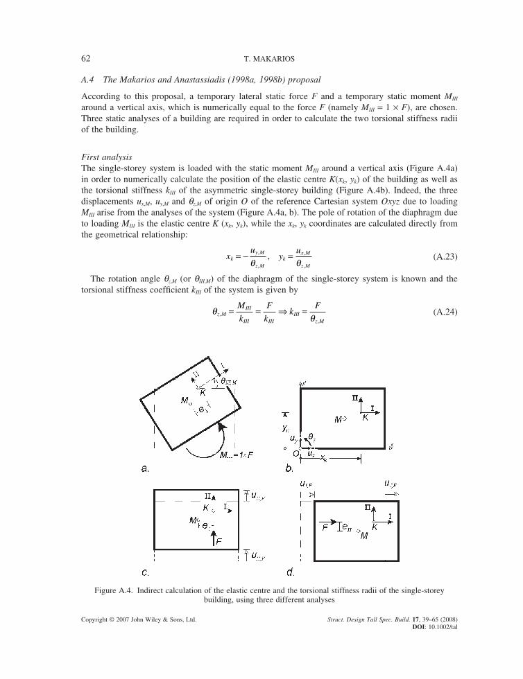
A.4 The Makarios and Anastassiadis (1998a, 1998b) proposal
According to this proposal, a temporary lateral static force F and a temporary static moment MIII around a vertical axis, which is numerically equal to the force F (namely MIII = 1 × F), are chosen. Three static analyses of a building are required in order to calculate the two torsional stiffness radii of the building.
First analysisThe single-storey system is loaded with the static moment MIII around a vertical axis (Figure A.4a) in order to numerically calculate the position of the elastic centre K(xk, yk) of the building as well as the torsional stiffness kIII of the asymmetric single-storey building (Figure A.4b). Indeed, the three displacements ux,M, uy,M and qz,M of origin O of the reference Cartesian system Oxyz due to loading MIII arise from the analyses of the system (Figure A.4a, b). The pole of rotation of the diaphragm due to loading MIII is the elastic centre K (xk, yk), while the xk, yk coordinates are calculated directly from the geometrical relationship:
xu
yu
ky M
z Mk
x M
z M
= − =,
,
,
,
,θ θ
(A.23)
The rotation angle qz,M (or qIII,M) of the diaphragm of the single-storey system is known and the torsional stiffness coeffi cient kIII of the system is given by
θθz M
III
III IIIIII
z M
M
k
F
kk
F,
,
= = ⇒ = (A.24)
Figure A.4. Indirect calculation of the elastic centre and the torsional stiffness radii of the single-storey building, using three different analyses
CALCULATION OF THE TORSIONAL STIFFNESS RADIUS OF MULTISTOREY BUILDINGS 63
Copyright © 2007 John Wiley & Sons, Ltd. Struct. Design Tall Spec. Build. 17, 39–65 (2008) DOI: 10.1002/tal
Second analysisThe single-storey system is loaded with the static force F that is applied at the elastic centre along the principal II-axis (Figure A.4c). In this case, the diaphragm of the system is translated with uII,F displacement along the principal II-axis without twist. Thus the translational stiffness coeffi cient kII of the system is given by
uF
kk
F
uII F
IIII
II F,
,
= ⇒ = (A.25)
Therefore, inserting Equations (A.24) and (A.25) into Equation (A.21a), the torsional stiffness radius rI along the principal I-axis of the single-storey system is given (Figure 4) by
ρ θθI
III
II
z M
II F
II F
z M
k
K
F
F u
u= = =,
,
,
,
(A.26)
Third analysisThe single-storey system is loaded with the static force F that is applied at the elastic centre along the principal I-axis (Figure A.4d). In this case, the diaphragm of the system is translated with uI,F displacement along the principal I-axis without twist. So, the translational stiffness coeffi cient kI of the system is given by
uF
kk
F
uI F
II
I F,
,
= ⇒ = (A.27)
Therefore, inserting Equationss (A.24) and (A.27) into Equation (A.21b) the torsional stiffness radius rII along the principal II-axis of the single-storey system is given (Figure 4) by
ρ θθII
III
I
z M
I F
I F
z M
k
K
F
F u
u= = =,
,
,
,
(A.28)
Hence, according to Equations (A.26) and (A.28) calculation of the stiffness coeffi cients kI kII, kIII of a single-storey building is not required for the calculation of the torsional stiffness radii of a system and it is very important in more complex systems, where the calculation of the stiffness coeffi cients is diffi cult or impossible, as is the case in asymmetric multistorey buildings.
A.5 The Tso and Moghadam (1998) proposal
According to Tso and Moghadam’s proposal, for each principal direction of the system two analyses of the system must be performed using the lateral static force F. In the fi rst analysis, the force F must be located at the mass centre M of the system; in the second analysis, the force F must be located with eccentricity +b × LI from the mass centre M to the fl exible side of the building (where LI is the perpendicular dimension of the building with reference to loading direction and b is a coeffi cient e.g. b = 0·05). The torsional stiffness radius rI of the system along the horizontal principal I-axis is given by Equation (A.29):
ρ ηI III
III I IL e L= × ⋅ ⋅ +( )
−−
× ( )0 5 1
1
∆∆
(A.29)
where ∆II = dmin/dmax; dmax is the maximum displacement of the fl exible side of the building due to the fi rst analysis; dmin is the maximum displacement of the stiff side of the building due to the fi rst analysis;
64 T. MAKARIOS
Copyright © 2007 John Wiley & Sons, Ltd. Struct. Design Tall Spec. Build. 17, 39–65 (2008) DOI: 10.1002/tal
hI = K̄G/LI with K̄G being the distance from the elastic centre K to the geometric centre G of the plan along the horizontal principal I-axis (the coeffi cient hI = K̄G/LI is different from the ratio eI/LI when the mass centre M does not coincide with the geometric centre G of the diaphragm).
Equation (A.30) gives the static eccentricity eI of the single-storey building:
eL
II III
III III
= × ×′ −β θ
θ θ (A.30)
where qIII is the rotation angle of the building, around a vertical axis, due to the fi rst analysis; and q ′III is the rotation angle of the building, around a vertical axis, due to the second analysis.
Equation (A.29) gives the second torsional stiffness radius rII of the single-storey building with alternation of indexes performing the same procedure as in the other two analyses along the normal horizontal principal direction.
Note that in order to calculate the torsional stiffness radius of a system either the Makarios and Anastassiadis proposal or that of Tso and Moghadam is applied; the same value of the torsional stiff-ness radius arises.
Finally, according to Tso and Moghadam (1998), buildings must possess the minimum torsional stiffness radius that is defi ned by Equation (A.31):
ρI IL> 0 30. (A.31)
The above indicative Equation (A.31) is different from the mathematical Equation (A.22a) from which the exact minimum torsional stiffness radius of a building arises in order for the building to be torsionally stiff.
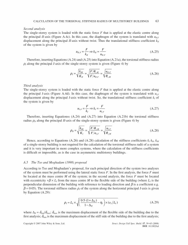
A.6 Numerical example of a single-storey building
Consider the monosymmetric single-storey building of Figure A.5, which consists of two unequal structural walls W1 and W2 along the y-direction and a structural wall W3 along the x-direction. The lateral translational stiffness of the two fi rst walls is kw1 = 1·20 k and kw2 = 1·00 k respectively, while that of the third wall W3 is kw3 = 1·00 k. The third structural wall, W3, does not contribute to the tor-
Figure A.5. Monosymmetric single-storey building of three structural walls W1, W2 and W3
CALCULATION OF THE TORSIONAL STIFFNESS RADIUS OF MULTISTOREY BUILDINGS 65
Copyright © 2007 John Wiley & Sons, Ltd. Struct. Design Tall Spec. Build. 17, 39–65 (2008) DOI: 10.1002/tal
sional stiffness of the building because it is located on the elastic centre K of the system. The structural walls are connected at their tops with a rigid deck that operates as a diaphragm around a vertical axis and we consider the Cartesian reference system Mxyz. The building has a torsional stiffness radius rI = 2·49 m that is derived from Equations (A.26) and (A.29). However, according to Calderoni et al.’s (2002) proposal the torsional stiffness radius is falsely calculated as 5·47 m. Moreover, the torsional stiffness radius rI,M with reference to the mass centre M of the system is calculated as rI,M = 2·50 m by Equation (A.22a). The contemporary Seismic Codes as well as the proposals of researchers disagree on whether this building is torsionally fl exible or torsionally stiff.
Indeed:
• According to UBC/1997 (Equation 30-16, s.1630·7 and Table 16-M), the coeffi cient of magni-tude Ax is less than one. Therefore, the building of Figure A.5 is torsionally stiff since Ax = (uII,fl ex/1·2 davg)2 = 0·982 is true.
• On the contrary, according to Section 2.3.1(3) (part 1-3) of Eurocode No. 8 (draft)/1998, the build-ing of Figure A.5 is torsionally fl exible because rI < 0·80 × r is true.
• According to (a) the criterion of Section 4.1.4.2b[3] of the Hellenic Seismic Code (EAK/2000), the building is torsionally stiff (see Section A.3 of the present paper).
• On the contrary, according to (b) and (c) the criteria of Section 4.1.4.2b[3] of the Hellenic Seismic Code (EAK/2000), the building is torsionally fl exible (see Section A.3 of the present paper).
• According to Equation (A.22a) of Anastassiadis et al.’s (1998) proposal, the building is torsionally fl exible.
• According to Equation (A.31) of Tso and Moghadam’s (1998) proposal, the building has the minimum required torsional stiffness since rI > 0·30LI is true.