Embed Size (px)
DESCRIPTION
ppap 4ta edicion
Citation preview
PRODUCTION PART APPROVAL PROCESS
(PPAP)
Production Part Approval Process (PPAP) First Edition Issued February 1993
Second Edition, 1st Printing, February 1995; 2nd Printing, July 1995 Third Edition, September 1999; 2nd Printing, August 2000
Fourth Edition, March 2006 Copyright ©1993, ©1995, ©1997, ©1999, ©2000, ©2006
DaimlerChrysler Corporation, Ford Motor Company, General Motors Corporation
Effective June 1, 2006, PPAP Fourth Edition replaces PPAP Third Edition unless otherwise specified by your customer.
Further copies are obtainable from AIAG at +1-248-358-3003 or AdareCarwin (UK) in Europe +44-1-708-861333
i
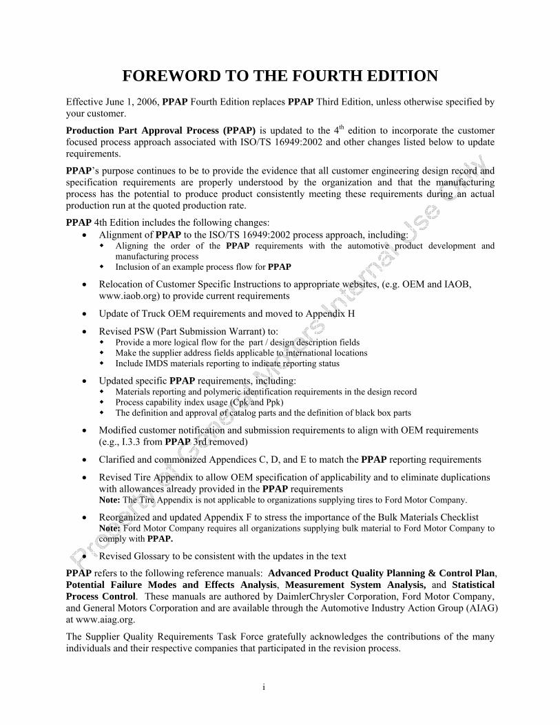
FOREWORD TO THE FOURTH EDITION
Effective June 1, 2006, PPAP Fourth Edition replaces PPAP Third Edition, unless otherwise specified by your customer.
Production Part Approval Process (PPAP) is updated to the 4th edition to incorporate the customer focused process approach associated with ISO/TS 16949:2002 and other changes listed below to update requirements.
PPAP’s purpose continues to be to provide the evidence that all customer engineering design record and specification requirements are properly understood by the organization and that the manufacturing process has the potential to produce product consistently meeting these requirements during an actual production run at the quoted production rate.
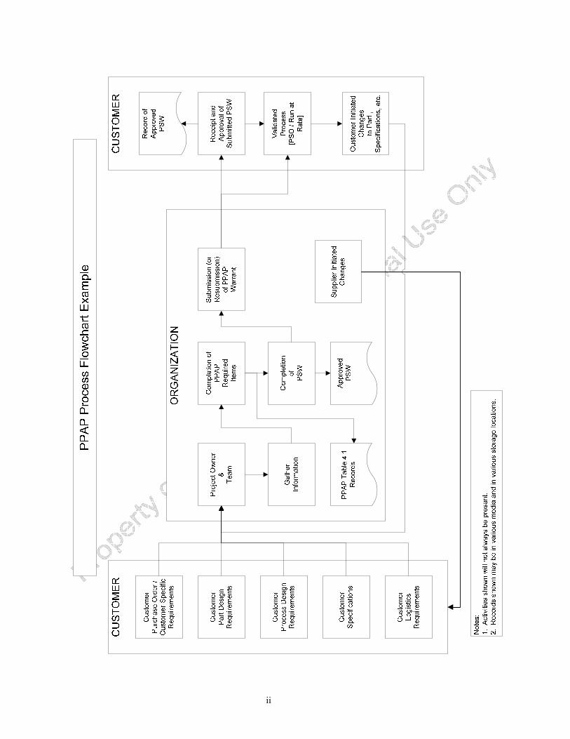
PPAP 4th Edition includes the following changes: • Alignment of PPAP to the ISO/TS 16949:2002 process approach, including:
Aligning the order of the PPAP requirements with the automotive product development and manufacturing process
Inclusion of an example process flow for PPAP
• Relocation of Customer Specific Instructions to appropriate websites, (e.g. OEM and IAOB, www.iaob.org) to provide current requirements
• Update of Truck OEM requirements and moved to Appendix H
• Revised PSW (Part Submission Warrant) to: Provide a more logical flow for the part / design description fields Make the supplier address fields applicable to international locations Include IMDS materials reporting to indicate reporting status
• Updated specific PPAP requirements, including: Materials reporting and polymeric identification requirements in the design record Process capability index usage (Cpk and Ppk) The definition and approval of catalog parts and the definition of black box parts
• Modified customer notification and submission requirements to align with OEM requirements (e.g., I.3.3 from PPAP 3rd removed)
• Clarified and commonized Appendices C, D, and E to match the PPAP reporting requirements
• Revised Tire Appendix to allow OEM specification of applicability and to eliminate duplications with allowances already provided in the PPAP requirements Note: The Tire Appendix is not applicable to organizations supplying tires to Ford Motor Company.
• Reorganized and updated Appendix F to stress the importance of the Bulk Materials Checklist Note: Ford Motor Company requires all organizations supplying bulk material to Ford Motor Company to comply with PPAP.
• Revised Glossary to be consistent with the updates in the text
PPAP refers to the following reference manuals: Advanced Product Quality Planning & Control Plan, Potential Failure Modes and Effects Analysis, Measurement System Analysis, and Statistical Process Control. These manuals are authored by DaimlerChrysler Corporation, Ford Motor Company, and General Motors Corporation and are available through the Automotive Industry Action Group (AIAG) at www.aiag.org.
The Supplier Quality Requirements Task Force gratefully acknowledges the contributions of the many individuals and their respective companies that participated in the revision process.
ii
iii
TABLE OF CONTENTS
INTRODUCTION.....................................................................................................................................................1 Purpose .................................................................................................................................................................1 Applicability..........................................................................................................................................................1 Approach ..............................................................................................................................................................1
SECTION 1 – GENERAL .........................................................................................................................................3
1.1 Submission of PPAP ................................................................................................................................3 SECTION 2 – PPAP PROCESS REQUIREMENTS.................................................................................................3
2.1 Significant Production Run......................................................................................................................3 2.2 PPAP Requirements.................................................................................................................................3
2.2.1 Design Record ......................................................................................................................................................... 4 2.2.2 Authorized Engineering Change documents ........................................................................................................... 5 2.2.3 Customer Engineering Approval ............................................................................................................................. 5 2.2.4 Design Failure Mode and Effects Analysis (Design FMEA)................................................................................... 5 2.2.5 Process Flow Diagram(s) ........................................................................................................................................ 5 2.2.6 Process Failure Mode and Effects Analysis (Process FMEA)................................................................................. 5 2.2.7 Control Plan............................................................................................................................................................. 5 2.2.8 Measurement System Analysis Studies ................................................................................................................... 6 2.2.9 Dimensional Results................................................................................................................................................ 6 2.2.10 Records of Material / Performance Test Results ................................................................................................... 6 2.2.11 Initial Process Studies............................................................................................................................................ 7 2.2.12 Qualified Laboratory Documentation.................................................................................................................. 10 2.2.13 Appearance Approval Report (AAR) .................................................................................................................. 10 2.2.14 Sample Production Parts...................................................................................................................................... 10 2.2.15 Master Sample..................................................................................................................................................... 10 2.2.16 Checking Aids ..................................................................................................................................................... 11 2.2.17 Customer-Specific Requirements ........................................................................................................................ 11 2.2.18 Part Submission Warrant (PSW) ......................................................................................................................... 11
SECTION 3 – CUSTOMER NOTIFICATION AND SUBMISSION REQUIREMENTS .....................................13
3.1 Customer Notification.................................................................................................................................13 3.2 Submission to Customer..............................................................................................................................15
SECTION 4 – SUBMISSION TO CUSTOMER - LEVELS OF EVIDENCE.........................................................17
4.1 Submission Levels .......................................................................................................................................17 SECTION 5 – PART SUBMISSION STATUS.......................................................................................................19
5.1 General .......................................................................................................................................................19 5.2 Customer PPAP Status ...............................................................................................................................19
5.2.1 Approved ........................................................................................................................................................... 19 5.2.2 Interim Approval ............................................................................................................................................... 19
iv
5.2.3 Rejected ............................................................................................................................................................. 19 SECTION 6 – RECORD RETENTION ..................................................................................................................21 APPENDICIES APPENDIX A – COMPLETION OF THE PART SUBMISSION WARRANT (PSW) .............................................................22 APPENDIX B – COMPLETION OF THE APPEARANCE APPROVAL REPORT...................................................................26 APPENDIX C – PRODUCTION PART APPROVAL, DIMENSIONAL RESULTS..................................................................29 APPENDIX D – PRODUCTION PART APPROVAL, MATERIAL TEST RESULTS ..............................................................31 APPENDIX E – PRODUCTION PART APPROVAL, PERFORMANCE TEST RESULTS........................................................33 APPENDIX F – BULK MATERIAL - SPECIFIC REQUIREMENTS ....................................................................................35 APPENDIX G – TIRES - SPECIFIC REQUIREMENTS .....................................................................................................57 APPENDIX H – TRUCK INDUSTRY - SPECIFIC REQUIREMENTS ..................................................................................59 GLOSSARY............................................................................................................................................................68
1
INTRODUCTION Purpose Production Part Approval Process (PPAP) defines generic requirements for production part approval, including production and bulk materials (see Glossary). The purpose of PPAP is to determine if all customer engineering design record and specification requirements are properly understood by the organization and that the manufacturing process has the potential to produce product consistently meeting these requirements during an actual production run at the quoted production rate.
Applicability PPAP shall apply to internal and external organization sites (see Glossary) supplying production parts, service parts, production materials, or bulk materials. For bulk materials, PPAP is not required unless specified by the authorized customer representative.
An organization supplying standard catalog production or service parts shall comply with PPAP unless formally waived by the authorized customer representative.
NOTE 1: See customer-specific requirements for additional information. All questions about PPAP should be addressed to the authorized customer representative. NOTE 2: A customer can formally waive PPAP requirements for an organization. Such waivers can only be issued by an authorized customer representative. NOTE 3: An organization or supplier requesting a waiver of a PPAP requirement should contact the authorized customer representative. The organization or supplier should obtain documentation of waivers from the authorized customer representative. NOTE 4: Catalog parts (e.g., bolts) are identified and/or ordered by functional specifications or by recognized industry standards.
Approach The word “shall” indicates mandatory requirements. The word “should” indicates a recommendation.
Paragraphs marked “NOTE” are for guidance in understanding or clarifying the associated requirement. The word “should” appearing in a NOTE is for guidance only.
For the purposes of PPAP, the terms and definitions given in ISO/TS 16949 and the PPAP Glossary apply.
2
3
SECTION 1 – GENERAL 1.1 Submission of PPAP The organization shall obtain approval (see 5.2.1) from the authorized customer representative for:
1. a new part or product (e.g., a specific part, material, or color not previously supplied to the specific customer).
2. correction of a discrepancy on a previously submitted part.
3. product modified by an engineering change to design records, specifications, or materials.
4. any situation required by Section 3. NOTE: If there is any question concerning the need for production part approval, contact the authorized customer representative.
SECTION 2 – PPAP PROCESS REQUIREMENTS 2.1 Significant Production Run For production parts, product for PPAP shall be taken from a significant production run. This significant production run shall be from one hour to eight hours of production, and with the specific production quantity to total a minimum of 300 consecutive parts, unless otherwise specified by the authorized customer representative.
This significant production run shall be conducted at the production site, at the production rate (see Glossary) using the production tooling, production gaging, production process, production materials, and production operators. Parts from each unique production process, e.g., duplicate assembly line and/or work cell, each position of a multiple cavity die, mold, tool or pattern, shall be measured and representative parts tested.
For bulk materials: No specific number of “parts” is required. The submitted sample shall be taken in a manner as to assure that it represents “steady-state” operation of the process.
NOTE: For bulk material, production histories of current products may often be used to estimate the initial process capability or performance of new and similar products. In cases where no production history of a similar bulk material product or technology exists, a containment plan may be put into effect until sufficient production has demonstrated capability or performance, unless otherwise specified by the customer.
2.2 PPAP Requirements The organization shall meet all specified PPAP requirements listed below (2.2.1 through 2.2.18). The organization shall also meet all customer-specific PPAP requirements.
Production parts shall meet all customer engineering design record and specification requirements (including safety and regulatory requirements).
Bulk Material PPAP requirements are defined by a completed Bulk Material Requirements Checklist (see Appendix F).
4
If any part specifications cannot be met, the organization shall document their problem-solving efforts and shall contact the authorized customer representative for concurrence in determination of appropriate corrective action.
NOTE: Items or records from 2.2.1 through 2.2.18 may not necessarily apply to every customer part number from every organization. For example, some parts do not have appearance requirements, others do not have color requirements, and plastic parts may have polymeric part marking requirements. In order to determine with certainty which items must be included, consult the design record, e.g., part print, the relevant Engineering documents or specifications, and your authorized customer representative.
2.2.1 Design Record The organization shall have the design record for the saleable product/part, including design records for components or details of the saleable product/part. Where the design record is in electronic format, e.g., CAD/CAM math data, the organization shall produce a hard copy (e.g., pictorial, geometric dimensioning & tolerancing [GD&T] sheets, drawing) to identify measurements taken.
NOTE 1: For any saleable product, part or component, there will only be one design record, regardless of who has design-responsibility. The design record may reference other documents making them part of the design record. NOTE 2: A single design record can represent multiple part or assembly configurations, e.g., a sub-frame assembly with various hole configurations for different applications. NOTE 3: For parts identified as black box (see Glossary), the design record specifies the interface and performance requirements. NOTE 4: For parts identified as catalog parts, the design record may consist only of a functional specification or a reference to a recognized industry standard. NOTE 5: For bulk materials, the design record may include identification of raw materials, formulations, processing steps and parameters, and final product specifications or acceptance criteria. If dimensional results do not apply, then CAD/CAM requirements are also not applicable.
2.2.1.1 Reporting of Part Material Composition
The organization shall provide evidence that the Material/Substance Composition reporting that is required by the customer has been completed for the part and that the reported data complies with all customer-specific requirements.
NOTE: This materials reporting may be entered into the IMDS (International Materials Data System) or other customer-specified system/method. IMDS is available through http://www.mdsystem.com/index.jsp.
2.2.1.2 Marking of Polymeric Parts
Where applicable, the organization shall identify polymeric parts with the ISO symbols such as specified in ISO 11469, “Plastics – Generic Identification and marking of plastic products” and/or ISO 1629, “Rubber and lattices – Nomenclature.” The following weight criteria shall determine if the marking requirement is applicable:
• Plastic parts weighing at least 100g (using ISO 11469/1043-1) • Elastomeric parts weighing at least 200g (using ISO 11469/1629) NOTE: Nomenclature and abbreviation references to support the use of ISO 11469 are contained in ISO 1043-1 for basic polymers and in ISO 1043-2 for fillers and reinforcements.
5
2.2.2 Authorized Engineering Change documents The organization shall have any authorized engineering change documents for those changes not yet recorded in the design record but incorporated in the product, part or tooling.
2.2.3 Customer Engineering Approval Where specified by the customer, the organization shall have evidence of customer engineering approval.
NOTE: For bulk materials, this requirement is satisfied by a signed ‘Engineering Approval’ line item on the Bulk Material Requirements Checklist (see Appendix F) and/or inclusion on a customer maintained list of approved materials.
2.2.4 Design Failure Mode and Effects Analysis (Design FMEA) if the organization is product design-responsible The product design-responsible organization shall develop a Design FMEA in accordance with, and compliant to, customer-specified requirements (e.g., Potential Failure Mode and Effects Analysis reference manual).
NOTE 1: A single Design FMEA may be applied to a family of similar parts or materials. NOTE 2: For bulk materials, see Appendix F.
2.2.5 Process Flow Diagram(s) The organization shall have a process flow diagram in an organization-specified format that clearly describes the production process steps and sequence, as appropriate, and meets the specified customer needs, requirements and expectations (e.g., Advanced Product Quality Planning and Control Plan reference manual). For bulk materials, an equivalent to a Process Flow Diagram is a Process Flow Description.
NOTE: Process flow diagrams for ‘families’ of similar parts are acceptable if the new parts have been reviewed for commonality by the organization.
2.2.6 Process Failure Mode and Effects Analysis (Process FMEA) The organization shall develop a Process FMEA in accordance with, and compliant to, customer-specified requirements, (e.g., Potential Failure Mode and Effects Analysis reference manual).
NOTE 1: A single Process FMEA may be applied to a process manufacturing a family of similar parts or materials if reviewed for commonality by the organization. NOTE 2: For bulk materials, see Appendix F.
2.2.7 Control Plan The organization shall have a Control Plan that defines all methods used for process control and complies with customer-specified requirements (e.g., Advanced Product Quality Planning and Control Plan reference manual).
NOTE 1: Control Plans for “families” of parts are acceptable if the new parts have been reviewed for commonality by the organization. NOTE 2: Control Plan approval may be required by certain customers.
6
2.2.8 Measurement System Analysis Studies The organization shall have applicable Measurement System Analysis studies, e.g., gage R&R, bias, linearity, stability, for all new or modified gages, measurement, and test equipment. (see the Measurement Systems Analysis reference manual).
NOTE 1: Gage R&R acceptability criteria are defined in the Measurement Systems Analysis reference manual. NOTE 2: For bulk materials, Measurement System Analysis may not apply. Customer agreement should be obtained on actual requirements.
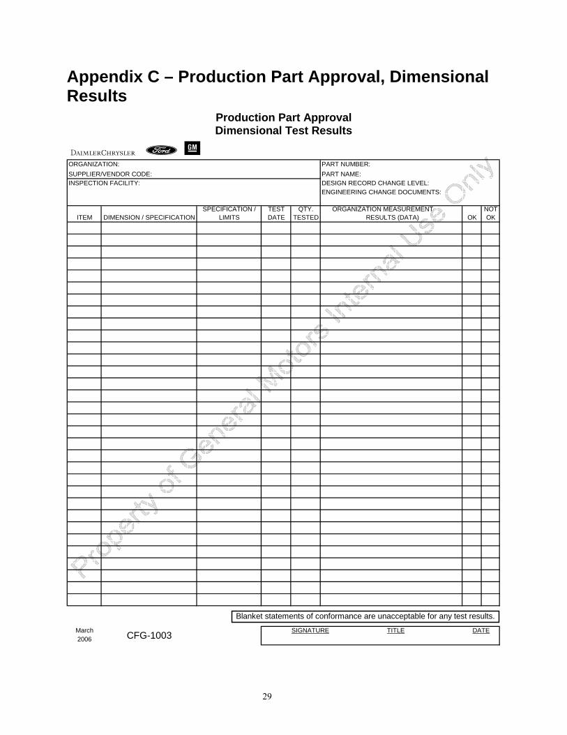
2.2.9 Dimensional Results The organization shall provide evidence that dimensional verifications required by the design record and the Control Plan have been completed and results indicate compliance with specified requirements. The organization shall have dimensional results for each unique manufacturing process, e.g., cells or production lines and all cavities, molds, patterns or dies (see 2.2.18). The organization shall record, with the actual results: all dimensions (except reference dimensions), characteristics, and specifications as noted on the design record and Control Plan.
The organization shall indicate the date of the design record, change level, and any authorized engineering change document not yet incorporated in the design record to which the part was made. The organization shall record the change level, drawing date, organization name and part number on all auxiliary documents (e.g., supplementary layout results sheets, sketches, tracings, cross sections, CMM inspection point results, geometric dimensioning and tolerancing sheets, or other auxiliary drawings used in conjunction with the part drawing). Copies of these auxiliary materials shall accompany the dimensional results according to the Retention/Submission Requirements Table. A tracing shall be included when an optical comparator is necessary for inspection.
The organization shall identify one of the parts measured as the master sample (see 2.2.15). NOTE 1: The Dimensional Results form in Appendix C, a pictorial, geometric dimensioning & tolerancing [GD&T] sheets, or a checked print where the results are legibly written on a part drawing including cross-sections, tracings, or sketches as applicable may be utilized for this purpose. NOTE 2: Dimensional results typically do not apply to bulk materials.
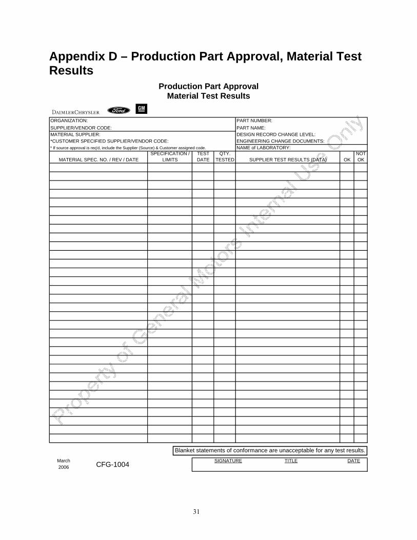
2.2.10 Records of Material / Performance Test Results The organization shall have records of material and/or performance test results for tests specified on the design record or Control Plan.
2.2.10.1 Material Test Results
The organization shall perform tests for all parts and product materials when chemical, physical, or metallurgical requirements are specified by the design record or Control Plan.
Material test results shall indicate and include:
• the design record change level of the parts tested; • any authorized engineering change documents that have not yet been incorporated in the
design record; • the number, date, and change level of the specifications to which the part was tested; • the date on which the testing took place; • the quantity tested;
7
• the actual results; • the material supplier’s name and, when required by the customer, the customer-assigned
supplier/vendor code. NOTE: Material test results may be presented in any convenient format. An example is shown in Appendix D.
For products with customer-developed material specifications and a customer-approved supplier list, the organization shall procure materials and/or services (e.g., painting, plating, heat-treating, welding) from suppliers on that list.
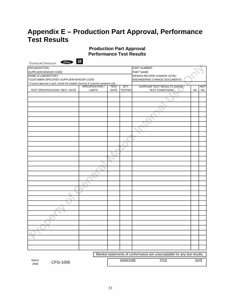
2.2.10.2 Performance Test Results
The organization shall perform tests for all part(s) or product material(s) when performance or functional requirements are specified by the design record or Control Plan.
Performance test results shall indicate and include:
• the design record change level of the parts tested; • any authorized engineering change documents that have not yet been incorporated in the
design record; • the number, date, and change level of the specifications to which the part was tested; • the date on which the testing took place; • the quantity tested; • the actual results. NOTE: Performance test results may be presented in any convenient format. An example is shown in Appendix E.
2.2.11 Initial Process Studies 2.2.11.1 General
The level of initial process capability or performance shall be determined to be acceptable prior to submission for all Special Characteristics designated by the customer or organization. The organization shall obtain customer concurrence on the index for estimating initial process capability prior to submission.
The organization shall perform measurement system analysis to understand how measurement error affects the study measurements. (see 2.2.8)
NOTE 1: Where no special characteristics have been identified, the customer reserves the right to require demonstration of initial process capability on other characteristics. NOTE 2: The purpose of this requirement is to determine if the production process is likely to produce product that will meet the customer’s requirements. The initial process study is focused on variables not attribute data. Assembly errors, test failures, surface defects are examples of attribute data, which is important to understand, but is not covered in this initial study. To understand the performance of characteristics monitored by attribute data will require more data collected over time. Unless approved by the authorized customer representative, attribute data are not acceptable for PPAP submissions. NOTE 3: Cpk and Ppk are described below. Other methods more appropriate for certain processes or products may be substituted with prior approval from an authorized customer representative. NOTE 4: Initial process studies are short-term and will not predict the effects of time and variation in people, materials, methods, equipment, measurement systems, and environment. Even for these short-term studies, it is important to collect and analyze the data in the order produced using control charts. NOTE 5: For those characteristics that can be studied using X-bar and R charts, a short-term study should be based on a minimum of 25 subgroups containing at least 100 readings from consecutive parts of the
8
significant production run (see 2.1). The initial process study data requirements may be replaced by longer-term historical data from the same or similar processes, with customer concurrence. For certain processes, alternative analytical tools such as individual and moving range charts may be appropriate and permitted with prior approval from an authorized customer representative.
2.2.11.2 Quality Indices
Initial process studies shall be summarized with capability or performance indices, if applicable. NOTE 1: The initial process study results are dependent on the purpose of the study, method of data acquisition, sampling, amount of data, demonstration of statistical control, etc. See the Statistical Process Control reference manual for additional information in understanding the basic principles of statistical stability and process measures (indices). For guidance on items listed below, contact the authorized customer representative. Cpk - The capability index for a stable process. The estimate of sigma is based on within subgroup variation (R-bar/d2 or S-bar/c4). Cpk is an indicator of process capability based on process variation within each subgroup of a set of data. Cpk does not include the effect of process variability between the subgroups. Cpk is an indicator of how good a process could be if all process variation between subgroups was to be eliminated. Therefore, use of Cpk alone may be an incomplete indicator of process performance. For more information, see the Statistical Process Control reference manual. Ppk - The performance index. The estimate of sigma is based on total variation (all of individual sample data using the standard deviation [root mean square equation], “s”). Ppk is an indicator of process performance based on process variation throughout the full set of data. Unlike Cpk, Ppk is not limited to the variation within subgroups. However, Ppk cannot isolate within subgroup variation from between subgroup variation. When calculated from the same data set, Cpk and Ppk can be compared to analyze the sources of process variation. For more information, see the Statistical Process Control reference manual. Initial Process Studies. The purpose of the initial process study is to understand the process variation, not just to achieve a specific index value. When historical data are available or enough initial data exist to plot a control chart (at least 100 individual samples), Cpk can be calculated when the process is stable. Otherwise, for processes with known and predictable special causes and output meeting specifications, Ppk should be used. When not enough data are available (< 100 samples) or there are unknown sources of variation, contact the authorized customer representative to develop a suitable plan.
NOTE 2: For Initial Process Studies involving more than one process stream, additional appropriate statistical methods or approaches may be required.
NOTE 3: For bulk material, the organization should obtain customer agreement regarding the appropriate techniques for initial process studies, if required, in order to determine an effective estimate of capability.
9
2.2.11.3 Acceptance Criteria for Initial Study
The organization shall use the following as acceptance criteria for evaluating initial process study results for processes that appear stable.
Results Interpretation
Index > 1.67 The process currently meets the acceptance criteria.
1.33 ≤ Index ≤ 1.67 The process may be acceptable. Contact the authorized customer representative for a review of the study results.
Index < 1.33 The process does not currently meet the acceptance criteria. Contact the authorized customer representative for a review of the study results.
NOTE 1: Meeting the initial process study capability acceptance criteria is one of a number of customer requirements that leads to an approved PPAP submission.
NOTE 2: See 2.2.11.1 and 2.2.11.2.
2.2.11.4 Unstable Processes
Depending on the nature of the instability, an unstable process may not meet customer requirements. The organization shall identify, evaluate and, wherever possible, eliminate special causes of variation prior to PPAP submission. The organization shall notify the authorized customer representative of any unstable processes that exist and shall submit a corrective action plan to the customer prior to any submission.
NOTE: For bulk materials, for processes with known and predictable special causes and output meeting specifications, corrective action plans may not be required by the customer.
2.2.11.5 Processes With One-Sided Specifications or Non-Normal Distributions
The organization shall determine with the authorized customer representative alternative acceptance criteria for processes with one-sided specifications or non-normal distributions.
NOTE: The above mentioned acceptance criteria (2.2.11.3) assume normality and a two-sided specification (target in the center). When this is not true, using this analysis may result in unreliable information. These alternate acceptance criteria could require a different type of index or some method of transformation of the data. The focus should be on understanding the reasons for the non-normality (e.g., is it stable over time?) and managing variation. Refer to the Statistical Process Control reference manual for further guidance.
2.2.11.6 Actions To Be Taken When Acceptance Criteria Are Not Satisfied
The organization shall contact the authorized customer representative if the acceptance criteria (2.2.11.3) cannot be attained by the required PPAP submission date. The organization shall submit to the authorized customer representative for approval a corrective action plan and a modified Control Plan normally providing for 100% inspection. Variation reduction efforts shall continue until the acceptance criteria are met, or until customer approval is received.
NOTE 1: 100% inspection methodologies are subject to review and concurrence by the customer. NOTE 2: For bulk materials, 100% inspection means an evaluation of a sample(s) of product from a continuous process or homogeneous batch which is representative of the entire production run.
10
2.2.12 Qualified Laboratory Documentation Inspection and testing for PPAP shall be performed by a qualified laboratory as defined by customer requirements (e.g., an accredited laboratory). The qualified laboratory (internal or external to the organization) shall have a laboratory scope and documentation showing that the laboratory is qualified for the type of measurements or tests conducted.
When an external/commercial laboratory is used, the organization shall submit the test results on the laboratory letterhead or the normal laboratory report format. The name of the laboratory that performed the tests, the date (s) of the tests, and the standards used to run the tests shall be identified.
2.2.13 Appearance Approval Report (AAR) A separate Appearance Approval Report (AAR) shall be completed for each part or series of parts if the product/part has appearance requirements on the design record.
Upon satisfactory completion of all required criteria, the organization shall record the required information on the AAR. The completed AAR and representative production products/parts shall be submitted to the location specified by the customer to receive disposition. AARs (complete with part disposition and authorized customer representative signature) shall then accompany the PSW at the time of final submission based upon the submission level requested. See customer-specific requirements for any additional requirements.
NOTE 1: AAR typically applies only for parts with color, grain, or surface appearance requirements. NOTE 2: Certain customers may not require entries in all AAR fields. See Appendix B or customer-specifics for detailed instructions on completing the AAR.
2.2.14 Sample Production Parts The organization shall provide sample product as specified by the customer.
2.2.15 Master Sample The organization shall retain a master sample for the same period as the production part approval records, or a) until a new master sample is produced for the same customer part number for customer approval, or b) where a master sample is required by the design record, Control Plan or inspection criteria, as a reference or standard. The master sample shall be identified as such, and shall show the customer approval date on the sample. The organization shall retain a master sample for each position of a multiple cavity die, mold, tool or pattern, or production process unless otherwise specified by the customer.
NOTE 1: When part size, sheer volume of parts, etc. makes storage of a master sample difficult, the sample retention requirements may be modified or waived in writing by the authorized customer representative. The purpose of the master sample is to assist in defining the production standard, especially where data is ambiguous or in insufficient detail to fully replicate the part to its original approved state. NOTE 2: Many bulk material properties are by their nature time dependent, and if a master sample is required, it may consist of the manufacturing record, test results, and certificate of analysis of key ingredients, for the approved submission sample. (see Appendix F).
11
2.2.16 Checking Aids If requested by the customer, the organization shall submit with the PPAP submission any part-specific assembly or component checking aid.
The organization shall certify that all aspects of the checking aid agree with part dimensional requirements. The organization shall document all released engineering design changes that have been incorporated in the checking aid at the time of submission. The organization shall provide for preventive maintenance of any checking aids for the life of the part (see Glossary - “Active Part”).
Measurement system analysis studies, e.g., gage R & R, accuracy, bias, linearity, stability studies, shall be conducted in compliance with customer requirements. (see 2.2.8 and the Measurement Systems Analysis reference manual).
NOTE 1: Checking aids can include fixtures, variable and attribute gages, models, templates, mylars specific to the product being submitted. NOTE 2: Checking aids, etc. typically do not apply to Bulk Materials. If checking aids are used for bulk materials, the organization should contact the authorized customer representative regarding this requirement.
2.2.17 Customer-Specific Requirements The organization shall have records of compliance to all applicable customer-specific requirements. For bulk materials, applicable customer-specific requirements shall be documented on the Bulk Material Requirements Checklist.
2.2.18 Part Submission Warrant (PSW) Upon completion of all PPAP requirements, the organization shall complete the Part Submission Warrant (PSW).
A separate PSW shall be completed for each customer part number unless otherwise agreed to by the authorized customer representative.
If production parts will be produced from more than one cavity, mold, tool, die, pattern, or production process, e.g., line or cell, the organization shall complete a dimensional evaluation (see 2.2.9) on one part from each. The specific cavities, molds, line, etc., shall then be identified in the “Mold/Cavity/Production Process” line on a PSW, or in a PSW attachment.
The organization shall verify that all of the measurement and test results show conformance with customer requirements and that all required documentation is available and, for Level 2, 3, and 4, is included in the submission as appropriate. A responsible official of the organization shall approve the PSW and provide contact information.
NOTE 1: One warrant per customer part number can be used to summarize many changes providing that the changes are adequately documented, and the submission is in compliance with customer program timing requirements. NOTE 2: PSWs may be submitted electronically in compliance with customer requirements.
12
2.2.18.1 Part Weight (Mass)
The organization shall record on the PSW the part weight of the part as shipped, measured and expressed in kilograms to four decimal places (0.0000) unless otherwise specified by the customer. The weight shall not include shipping protectors, assembly aides, or packaging materials. To determine part weight, the organization shall individually weigh ten randomly selected parts, calculate and report the average weight. At least one part shall be measured from each cavity, tool, line or process to be used in product realization.
NOTE: This weight is used for vehicle weight analysis only and does not affect the approval process. Where there is no production or service requirement for at least ten parts, the organization should use the required number for calculation of the average part weight. For bulk materials, the part weight field is not applicable.
13
SECTION 3 – CUSTOMER NOTIFICATION AND SUBMISSION REQUIREMENTS
3.1 Customer Notification The organization shall notify the authorized customer representative of any planned changes to the design, process, or site. Examples are indicated in the table below (see Table 3.1).
NOTE: Organizations are responsible to notify the authorized customer representative of all changes to the part design and/or the manufacturing process.
Upon notification and approval of the proposed change by the authorized customer representative, and after change implementation, PPAP submission is required unless otherwise specified.
Table 3.1 Examples of changes requiring
notification Clarifications
1. Use of other construction or material than was used in the previously approved part or product
For example, other construction as documented on a deviation (permit) or included as a note on the design record and not covered by an engineering change as described in Table 3.2, #3.
2. Production from new or modified tools (except perishable tools), dies, molds patterns, etc. including additional or replacement tooling
This requirement only applies to tools, which due to their unique form or function, can be expected to influence the integrity of the final product. It is not meant to describe standard tools (new or repaired), such as standard measuring devices, drivers (manual or power), etc.
3. Production following upgrade or rearrangement of existing tooling or equipment.
Upgrade means the reconstruction and/or modification of a tool or machine or to increase the capacity, performance, or change its existing function. This is not meant to be confused with normal maintenance, repair or replacement of parts, etc., for which no change in performance is to be expected and post repair verification methods have been established. Rearrangement is defined as activity that changes the sequence of product/process flow from that documented in the process flow diagram (including the addition of a new process). Minor adjustments of production equipment may be required to meet safety requirements such as, installation of protective covers, elimination of potential ESD risks, etc.
4. Production from tooling and equipment transferred to a different plant site or from an additional plant site.
Production process tooling and /or equipment transferred between buildings or facilities at one or more sites.
5. Change of supplier for parts, non-equivalent materials, or services (e.g., heat-treating, plating).
The organization is responsible for approval of supplier provided material and services.
14
6. Product produced after the tooling has been inactive for volume production for twelve months or more.
For product that has been produced after tooling has been inactive for twelve months or more: Notification is required when the part has had no change in active purchase order and the existing tooling has been inactive for volume production for twelve months or more. The only exception is when the part has low volume, e.g., service or specialty vehicles. However a customer may specify certain PPAP requirements for service parts.
7. Product and process changes related to components of the production product manufactured internally or manufactured by suppliers.
Any changes, including changes at the suppliers to the organization and their suppliers, that affect customer requirements, e.g., fit, form, function, performance, durability.
8. Change in test/inspection method – new technique (no effect on acceptance criteria)
For change in test method, the organization should have evidence that the new method has measurement capability equivalent to the old method.
Additionally, for bulk materials: 9. New source of raw material from new or existing supplier. 10. Change in product appearance attributes
These changes would normally be expected to have an effect on the performance of the product.
15
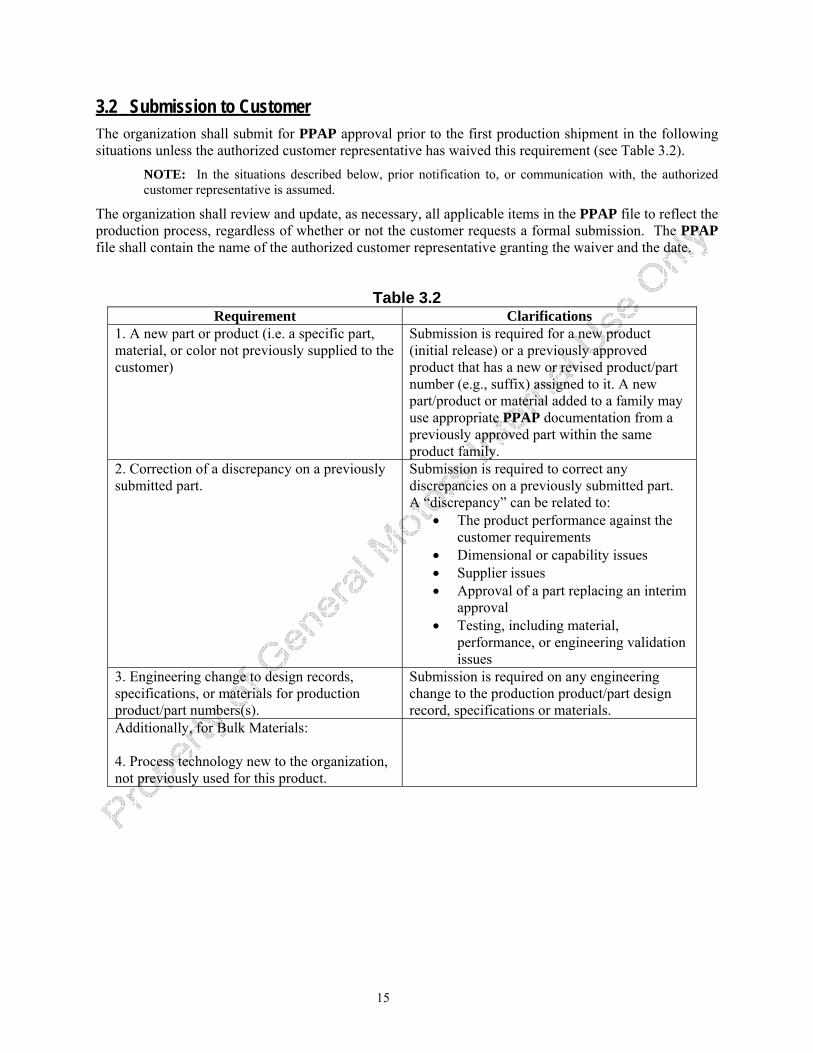
3.2 Submission to Customer The organization shall submit for PPAP approval prior to the first production shipment in the following situations unless the authorized customer representative has waived this requirement (see Table 3.2).
NOTE: In the situations described below, prior notification to, or communication with, the authorized customer representative is assumed.
The organization shall review and update, as necessary, all applicable items in the PPAP file to reflect the production process, regardless of whether or not the customer requests a formal submission. The PPAP file shall contain the name of the authorized customer representative granting the waiver and the date.
Table 3.2 Requirement Clarifications
1. A new part or product (i.e. a specific part, material, or color not previously supplied to the customer)
Submission is required for a new product (initial release) or a previously approved product that has a new or revised product/part number (e.g., suffix) assigned to it. A new part/product or material added to a family may use appropriate PPAP documentation from a previously approved part within the same product family.
2. Correction of a discrepancy on a previously submitted part.
Submission is required to correct any discrepancies on a previously submitted part. A “discrepancy” can be related to:
• The product performance against the customer requirements
• Dimensional or capability issues • Supplier issues • Approval of a part replacing an interim
approval • Testing, including material,
performance, or engineering validation issues
3. Engineering change to design records, specifications, or materials for production product/part numbers(s).
Submission is required on any engineering change to the production product/part design record, specifications or materials.
Additionally, for Bulk Materials: 4. Process technology new to the organization, not previously used for this product.
16
17
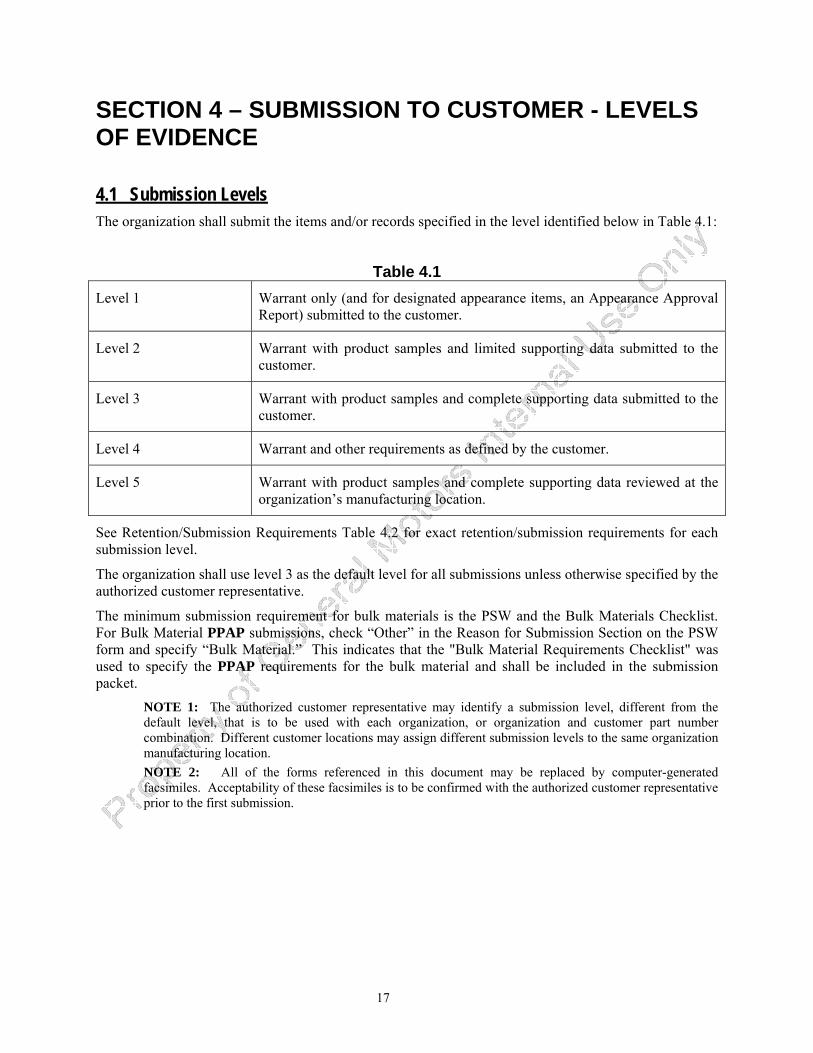
SECTION 4 – SUBMISSION TO CUSTOMER - LEVELS OF EVIDENCE
4.1 Submission Levels The organization shall submit the items and/or records specified in the level identified below in Table 4.1:
Table 4.1 Level 1 Warrant only (and for designated appearance items, an Appearance Approval
Report) submitted to the customer.
Level 2 Warrant with product samples and limited supporting data submitted to the customer.
Level 3 Warrant with product samples and complete supporting data submitted to the customer.
Level 4 Warrant and other requirements as defined by the customer.
Level 5 Warrant with product samples and complete supporting data reviewed at the organization’s manufacturing location.
See Retention/Submission Requirements Table 4.2 for exact retention/submission requirements for each submission level.
The organization shall use level 3 as the default level for all submissions unless otherwise specified by the authorized customer representative.
The minimum submission requirement for bulk materials is the PSW and the Bulk Materials Checklist. For Bulk Material PPAP submissions, check “Other” in the Reason for Submission Section on the PSW form and specify “Bulk Material.” This indicates that the "Bulk Material Requirements Checklist" was used to specify the PPAP requirements for the bulk material and shall be included in the submission packet.
NOTE 1: The authorized customer representative may identify a submission level, different from the default level, that is to be used with each organization, or organization and customer part number combination. Different customer locations may assign different submission levels to the same organization manufacturing location. NOTE 2: All of the forms referenced in this document may be replaced by computer-generated facsimiles. Acceptability of these facsimiles is to be confirmed with the authorized customer representative prior to the first submission.
18
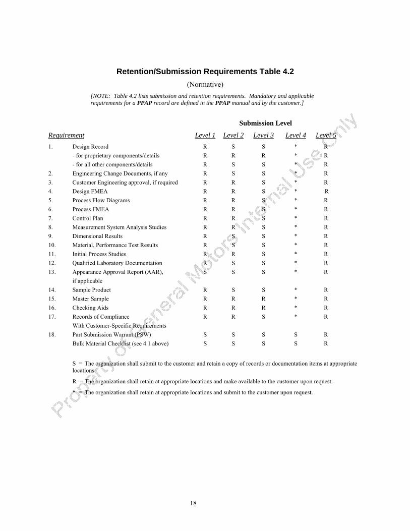
Retention/Submission Requirements Table 4.2 (Normative)
[NOTE: Table 4.2 lists submission and retention requirements. Mandatory and applicable requirements for a PPAP record are defined in the PPAP manual and by the customer.]
Submission Level
Requirement Level 1 Level 2 Level 3 Level 4 Level 51. Design Record R S S * R - for proprietary components/details R R R * R - for all other components/details R S S * R 2. Engineering Change Documents, if any R S S * R 3. Customer Engineering approval, if required R R S * R 4. Design FMEA R R S * R 5. Process Flow Diagrams R R S * R 6. Process FMEA R R S * R 7. Control Plan R R S * R 8. Measurement System Analysis Studies R R S * R 9. Dimensional Results R S S * R 10. Material, Performance Test Results R S S * R 11. Initial Process Studies R R S * R 12. Qualified Laboratory Documentation R S S * R 13. Appearance Approval Report (AAR), S S S * R if applicable 14. Sample Product R S S * R 15. Master Sample R R R * R 16. Checking Aids R R R * R 17. Records of Compliance R R S * R With Customer-Specific Requirements 18. Part Submission Warrant (PSW) S S S S R Bulk Material Checklist (see 4.1 above) S S S S R
S = The organization shall submit to the customer and retain a copy of records or documentation items at appropriate locations.
R = The organization shall retain at appropriate locations and make available to the customer upon request.
* = The organization shall retain at appropriate locations and submit to the customer upon request.
19
SECTION 5 – PART SUBMISSION STATUS
5.1 General Upon approval of the submission, the organization shall assure that future production continues to meet all customer requirements.
NOTE: For those organizations that have been classified as “self certifying” (PPAP submission level 1) by a specific customer, submission of the required organization-approved documentation will be considered as customer approval unless the organization is advised otherwise.
5.2 Customer PPAP Status 5.2.1 Approved Approved indicates that the part or material, including all sub-components, meets all customer requirements. The organization is therefore authorized to ship production quantities of the product, subject to releases from the customer scheduling activity.
5.2.2 Interim Approval Interim Approval permits shipment of material for production requirements on a limited time or piece quantity basis. Interim Approval will only be granted when the organization has:
• clearly defined the non-compliances preventing approval; and, • prepared an action plan agreed upon by the customer. PPAP re-submission is required to
obtain a status of “approved.” Note 1: The organization is responsible for implementing containment actions to ensure that only acceptable material is being shipped to the customer. Note 2: Parts with a status of “Interim Approval” are not to be considered “Approved.”
Material covered by an interim approval that fails to meet the agreed-upon action plan, either by the expiration date or the shipment of the authorized quantity, will be rejected. No additional shipments are authorized unless an extension of the interim approval is granted.
For bulk materials, the organization shall use the “Bulk Material Interim Approval” form, or its equivalent (see Appendix F).
5.2.3 Rejected Rejected means that the PPAP submission does not meet customer requirements, based on the production lot from which it was taken and/or accompanying documentation. In such cases, the submission and/or process, as appropriate, shall be corrected to meet customer requirements. The submission shall be approved before production quantities may be shipped.

20
21
SECTION 6 – RECORD RETENTION
PPAP records (see 2.2), regardless of submission level, shall be maintained for the length of time that the part is active (see Glossary) plus one calendar year.
The organization shall ensure that the appropriate PPAP records from a superseded part PPAP file are included, or referenced in the new part PPAP file.
NOTE: An example of an appropriate document/record that should be carried forward from the old file to the new part file would be a material certification from a raw material supplier for a new part that represents only a dimensional change from the old part number. This should be identified by conducting a PPAP “gap analysis” between the old and new part numbers.
22
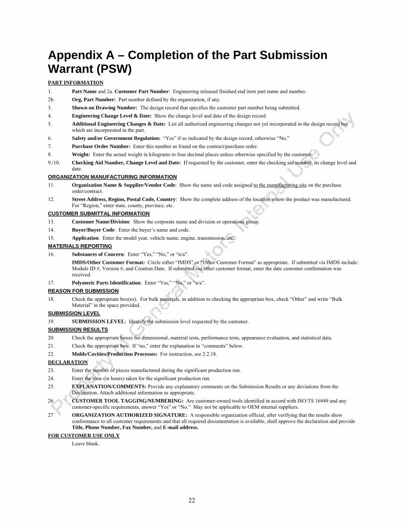
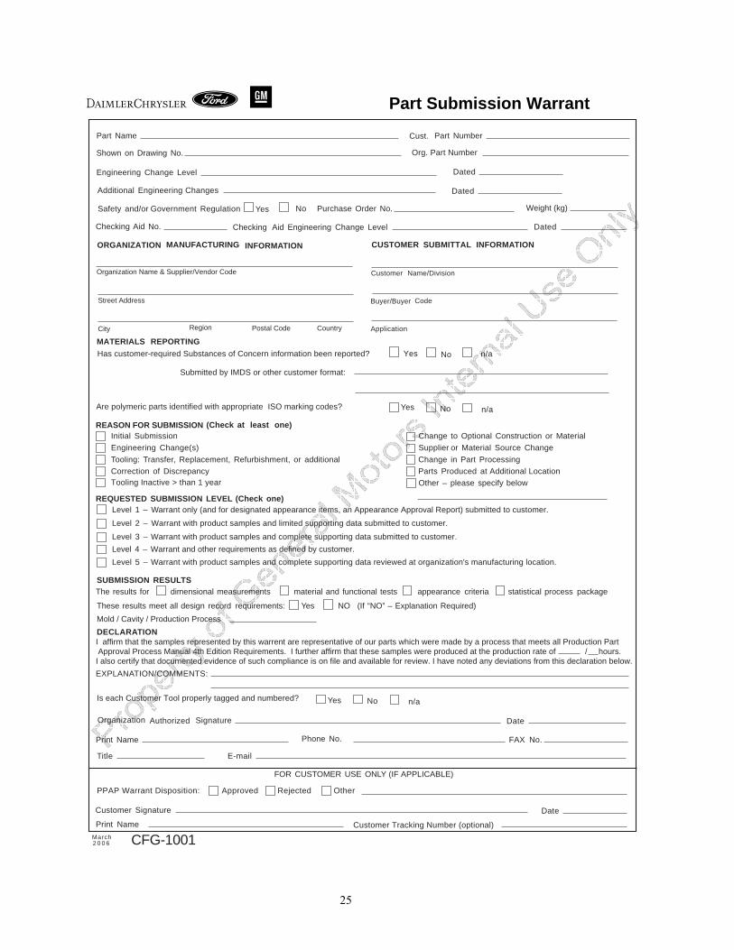
Appendix A – Completion of the Part Submission Warrant (PSW) PART INFORMATION1. Part Name and 2a. Customer Part Number: Engineering released finished end item part name and number. 2b. Org, Part Number: Part number defined by the organization, if any. 3. Shown on Drawing Number: The design record that specifies the customer part number being submitted. 4. Engineering Change Level & Date: Show the change level and date of the design record. 5. Additional Engineering Changes & Date: List all authorized engineering changes not yet incorporated in the design record but
which are incorporated in the part. 6. Safety and/or Government Regulation: “Yes” if so indicated by the design record, otherwise “No.” 7. Purchase Order Number: Enter this number as found on the contract/purchase order. 8. Weight: Enter the actual weight in kilograms to four decimal places unless otherwise specified by the customer. 9./10. Checking Aid Number, Change Level and Date: If requested by the customer, enter the checking aid number, its change level and
date. ORGANIZATION MANUFACTURING INFORMATION11. Organization Name & Supplier/Vendor Code: Show the name and code assigned to the manufacturing site on the purchase
order/contract. 12. Street Address, Region, Postal Code, Country: Show the complete address of the location where the product was manufactured.
For “Region,” enter state, county, province, etc. CUSTOMER SUBMITTAL INFORMATION13. Customer Name/Division: Show the corporate name and division or operations group. 14. Buyer/Buyer Code: Enter the buyer’s name and code. 15. Application: Enter the model year, vehicle name, engine, transmission, etc. MATERIALS REPORTING16. Substances of Concern: Enter “Yes,” “No,” or “n/a”. IMDS/Other Customer Format: Circle either “IMDS” or “Other Customer Format” as appropriate. If submitted via IMDS include:
Module ID #, Version #, and Creation Date. If submitted via other customer format, enter the date customer confirmation was received.
17. Polymeric Parts Identification: Enter “Yes,” “No,” or “n/a”. REASON FOR SUBMISSION18. Check the appropriate box(es). For bulk materials, in addition to checking the appropriate box, check “Other” and write “Bulk
Material” in the space provided. SUBMISSION LEVEL19. SUBMISSION LEVEL: Identify the submission level requested by the customer. SUBMISSION RESULTS20. Check the appropriate boxes for dimensional, material tests, performance tests, appearance evaluation, and statistical data. 21. Check the appropriate box. If “no,” enter the explanation in “comments” below. 22. Molds/Cavities/Production Processes: For instruction, see 2.2.18. DECLARATION 23. Enter the number of pieces manufactured during the significant production run. 24. Enter the time (in hours) taken for the significant production run. 25. EXPLANATION/COMMENTS: Provide any explanatory comments on the Submission Results or any deviations from the
Declaration. Attach additional information as appropriate. 26 CUSTOMER TOOL TAGGING/NUMBERING: Are customer-owned tools identified in accord with ISO/TS 16949 and any
customer-specific requirements, answer “Yes” or “No.” May not be applicable to OEM internal suppliers. 27 ORGANIZATION AUTHORIZED SIGNATURE: A responsible organization official, after verifying that the results show
conformance to all customer requirements and that all required documentation is available, shall approve the declaration and provide Title, Phone Number, Fax Number, and E-mail address.
FOR CUSTOMER USE ONLY Leave blank.
23
Part Submission Warrant Part Name Part Cust. Number
Safety and/or Government Regulation
Yes No
Org. Part Number
Dated
Additional Engineering Changes Dated
Shown on Drawing No.
Purchase Order No. Weight (kg)
Checking Aid No.
Engineering Change Level
Change Level Dated
ORGANIZATION MANUFACTURING
MATERIALS REPORTING
INFORMATION SUBMITTAL CUSTOMER INFORMATION
EngineeringChecking Aid
Yes No
n/a
Yes No n/a
Supplier Name & Supplier/Vendor Code
Street Address
City Region Postal Code Country
Customer Name/Division
Buyer/Buyer Code
Application
REASON FOR SUBMISSIONInitial Submission Change to Optional Construction or Material
Engineering Change(s) Supplier or Material Source Change
Tooling: Transfer, Replacement, Refurbishment, or additional Change in Part Processing
Tooling Inactive > than 1 yearCorrection of Discrepancy Parts Produced at Additional Location
Other – please specify
REQUESTED SUBMISSION LEVEL
(Check at least one)
(Check one)Level 1 – Warrant only (and for designated appearance items, an Appearance Approval Report) submitted to customer.
Has customer-required Substances of Concern information been reported?.
Are polymeric parts identified with appropriate ISO marking codes?
Yes NoIs each Customer Tool properly tagged and numbered?
Submitted by IMDS or other customer format:
Level 2 – Warrant with product samples and limited supporting data submitted to customer.
Level 3 – Warrant with product samples and complete supporting data submitted to customer.
Level 4 – Warrant and other requirements as defined by customer.
Level 5 – Warrant with product samples and complete supporting data reviewed at organization's manufacturing location.
SUBMISSION RESULTSThe results for dimensional measurements material and functional tests appearance criteria statistical process package
These results meet all design record requirements:
Mold / Cavity / Production Process Yes NO (If “NO” – Explanation Required)
DECLARATIONI affirm that the samples represented by this warrent are representative of our parts, which were made by a process that meets all Production Part Approval Process Manual 4th Edition Requirements. I further affirm that these samples were produced at the production rate of / hours.I also certify that documented evidence of such compliance is on file and available for review. I have noted any deviations from this declaration below.
EXPLANATION/COMMENTS:
Print Name
Phone No.
Organization Authorized Signature Date
1 2a
2b3
4
5
876
109
11 13
12 14
15
16
FOR CUSTOMER USE ONLY (IF APPLICABLE)
ApprovedPPAP Warrant Disposition: Rejected
Print Name
Customer
Customer Tracking Number (optional)
Signature Date
Other
March2 0 0 6 CFG-1001
Title
FAX No.
17
18
19
20
2122
23 24
2526
27

24
25
Part Submission Warrant
Part Name Part Cust. Number
Safety and/or Government Regulation
Yes No
Org. Part Number
Dated
Additional Engineering Changes Dated
Shown on Drawing No.
Purchase Order No. Weight (kg)
Checking Aid No.
Engineering Change Level
Change Level Dated
ORGANIZATION MANUFACTURING
MATERIALS REPORTING
INFORMATION SUBMITTAL CUSTOMER INFORMATION
EngineeringChecking Aid
Yes No
n/a
Organization Name & Supplier/Vendor Code
Street Address
City Region Postal Code Country
Customer Name/Division
Buyer/Buyer Code
Application
Yes No n/a
REASON FOR SUBMISSIONInitial Submission Change to Optional Construction or Material
Engineering Change(s) Supplier or Material Source Change
Tooling: Transfer, Replacement, Refurbishment, or additional Change in Part Processing
Tooling Inactive > than 1 yearCorrection of Discrepancy Parts Produced at Additional Location
Other – please specify below
REQUESTED SUBMISSION LEVEL
(Check at least one)
(Check one)Level 1 – Warrant only (and for designated appearance items, an Appearance Approval Report) submitted to customer.
Has customer-required Substances of Concern information been reported?
Are polymeric parts identified with appropriate ISO marking codes?
Yes No n/aIs each Customer Tool properly tagged and numbered?
Submitted by IMDS or other customer format:
Level 2 – Warrant with product samples and limited supporting data submitted to customer.
Level 3 – Warrant with product samples and complete supporting data submitted to customer.
Level 4 – Warrant and other requirements as defined by customer.
Level 5 – Warrant with product samples and complete supporting data reviewed at organization's manufacturing location.
SUBMISSION RESULTSThe results for dimensional measurements material and functional tests appearance criteria statistical process package
These results meet all design record requirements:
Mold / Cavity / Production Process Yes NO (If “NO” – Explanation Required)
DECLARATIONI affirm that the samples represented by this warrent are representative of our parts which were made by a process that meets all Production Part Approval Process Manual 4th Edition Requirements. I further affirm that these samples were produced at the production rate of / hours.I also certify that documented evidence of such compliance is on file and available for review. I have noted any deviations from this declaration below.
EXPLANATION/COMMENTS:
Print Name
Phone No.
Organization Authorized Signature Date
FOR CUSTOMER USE ONLY (IF APPLICABLE)
ApprovedPPAP Warrant Disposition: Rejected
Print Name
Customer
Customer Tracking Number (optional)
Signature Date
Other
FAX No.
Title
March2 0 0 6 CFG-1001
26
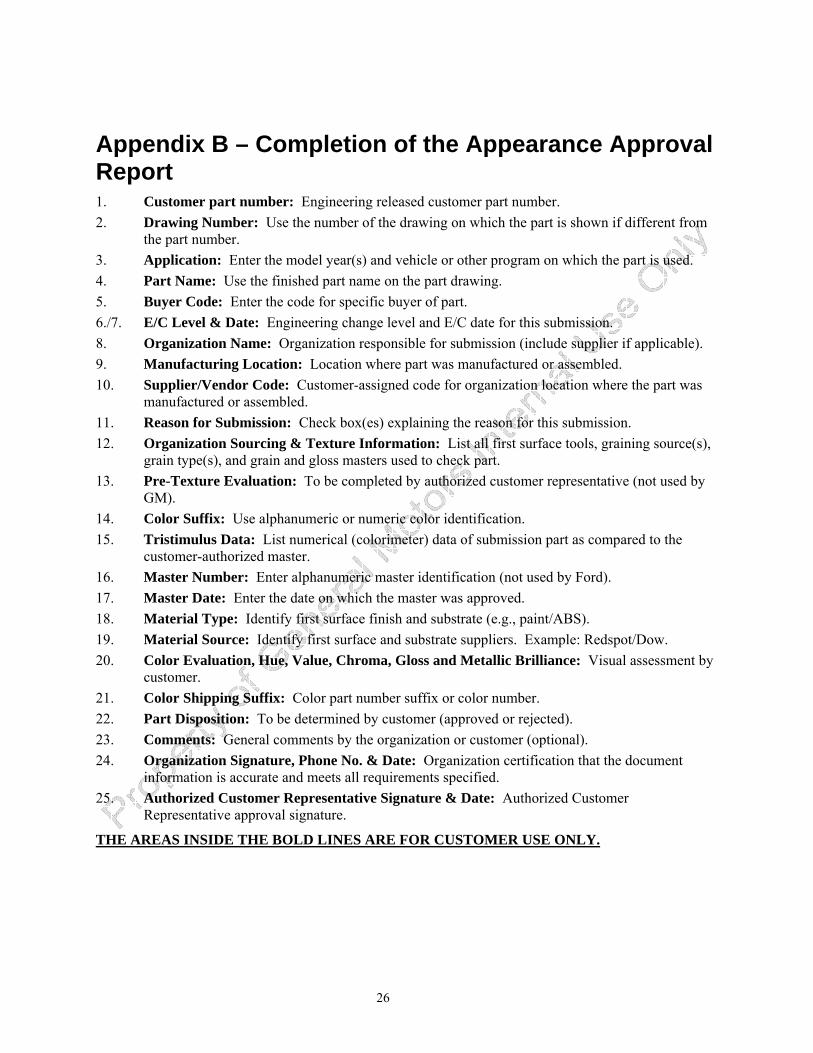
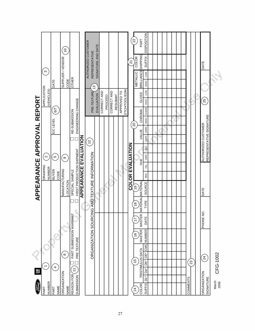
Appendix B – Completion of the Appearance Approval Report 1. Customer part number: Engineering released customer part number. 2. Drawing Number: Use the number of the drawing on which the part is shown if different from
the part number. 3. Application: Enter the model year(s) and vehicle or other program on which the part is used. 4. Part Name: Use the finished part name on the part drawing. 5. Buyer Code: Enter the code for specific buyer of part. 6./7. E/C Level & Date: Engineering change level and E/C date for this submission. 8. Organization Name: Organization responsible for submission (include supplier if applicable). 9. Manufacturing Location: Location where part was manufactured or assembled. 10. Supplier/Vendor Code: Customer-assigned code for organization location where the part was
manufactured or assembled. 11. Reason for Submission: Check box(es) explaining the reason for this submission. 12. Organization Sourcing & Texture Information: List all first surface tools, graining source(s),
grain type(s), and grain and gloss masters used to check part. 13. Pre-Texture Evaluation: To be completed by authorized customer representative (not used by
GM). 14. Color Suffix: Use alphanumeric or numeric color identification. 15. Tristimulus Data: List numerical (colorimeter) data of submission part as compared to the
customer-authorized master. 16. Master Number: Enter alphanumeric master identification (not used by Ford). 17. Master Date: Enter the date on which the master was approved. 18. Material Type: Identify first surface finish and substrate (e.g., paint/ABS). 19. Material Source: Identify first surface and substrate suppliers. Example: Redspot/Dow. 20. Color Evaluation, Hue, Value, Chroma, Gloss and Metallic Brilliance: Visual assessment by
customer. 21. Color Shipping Suffix: Color part number suffix or color number. 22. Part Disposition: To be determined by customer (approved or rejected). 23. Comments: General comments by the organization or customer (optional). 24. Organization Signature, Phone No. & Date: Organization certification that the document
information is accurate and meets all requirements specified. 25. Authorized Customer Representative Signature & Date: Authorized Customer
Representative approval signature.
THE AREAS INSIDE THE BOLD LINES ARE FOR CUSTOMER USE ONLY.
27
A
PPEA
RA
NC
E A
PPR
OVA
L R
EPO
RT
PA
RT
DR
AW
ING
AP
PLI
CA
TIO
NN
UM
BE
RN
UM
BE
R(V
EH
ICLE
S)
PA
RT
BU
YE
RE
/C L
EV
EL
DA
TEN
AM
EC
OD
EO
RG
AN
IZA
TIO
NM
AN
UFA
CTU
RIN
GS
UP
PLI
ER
/ V
EN
DO
RN
AM
ELO
CA
TIO
NC
OD
ER
EA
SO
N F
OR
PA
RT
SU
BM
ISS
ION
WA
RR
AN
TS
PE
CIA
L S
AM
PLE
RE
-SU
BM
ISS
ION
OTH
ER
SU
BM
ISS
ION
PR
E T
EXT
UR
EFI
RS
T P
RO
DU
CTI
ON
SH
IPM
EN
TE
NG
INE
ER
ING
CH
AN
GE
APP
EAR
AN
CE
EVAL
UAT
ION
AU
THO
RIZ
ED
CU
STO
ME
R
PR
E-T
EXT
UR
ER
EP
RE
SE
NTA
TIV
E
EV
ALU
ATI
ON
SIG
NA
TUR
E A
ND
DA
TEC
OR
RE
CT
AN
DP
RO
CE
ED
CO
RR
EC
T A
ND
RE
SU
BM
ITA
PP
RO
VE
D T
OE
TCH
/TO
OL/
ED
M
CO
LOR
EVA
LUA
TIO
NC
OLO
RC
OLO
RTR
ISTI
MU
LUS
DA
TAM
AS
TER
MA
STE
RM
ATE
RIA
LM
ATE
RIA
LH
UE
VA
LUE
CH
RO
MA
GLO
SS
BR
ILLI
AN
CE
SH
IPP
ING
PA
RT
SU
FFIX
DL*
Da*
Db*
DE
*C
MC
NU
MB
ER
DA
TETY
PE
SO
UR
CE
RED
YE
LG
RN
BLU
LIG
HT
DA
RK
GR
AY
CLE
ANH
IGH
LOW
HIG
HLO
WS
UFF
IXD
ISP
OS
ITIO
N
CO
MM
EN
TS
OR
GA
NIZ
ATI
ON
PH
ON
E N
O.
DA
TEA
UTH
OR
IZE
D C
US
TOM
ER
DA
TES
IGN
ATU
RE
RE
PR
ES
EN
TATI
VE
SIG
NA
TUR
E
OR
GA
NIZ
ATI
ON
SO
UR
CIN
G A
ND
TE
XTU
RE
INFO
RM
ATI
ON
ME
TALL
IC
CFG
-100
2M
arch
2006
22
10
21
3
13
25
6/7
20
12
2 5 9
1918
1716
8
24
15 23
1 4
11
14
28
APPE
ARAN
CE
APPR
OVA
L R
EPO
RT
PAR
TD
RA
WIN
GA
PP
LIC
ATI
ON
NU
MB
ER
NU
MB
ER
(VE
HIC
LES
)PA
RT
BU
YE
RE
/C L
EV
EL
DA
TEN
AME
CO
DE
SU
PP
LIE
RM
AN
UFA
CTU
RIN
GS
UP
PLI
ER
/ V
EN
DO
RN
AME
LOC
ATI
ON
CO
DE
RE
AS
ON
FO
RP
AR
T S
UB
MIS
SIO
N W
AR
RA
NT
SP
EC
IAL
SA
MP
LER
E-S
UB
MIS
SIO
NO
THE
RSU
BM
ISS
ION
PR
E TE
XTU
RE
FIR
ST
PR
OD
UC
TIO
N S
HIP
ME
NT
EN
GIN
EER
ING
CH
AN
GE
APPE
ARAN
CE
EVAL
UA
TIO
NA
UTH
OR
IZE
D C
US
TOM
ER
P
RE
-TE
XTU
RE
RE
PR
ES
EN
TATI
VE
E
VA
LUA
TIO
NS
IGN
ATU
RE
AN
D D
ATE
CO
RR
EC
T A
ND
PR
OC
EE
DC
OR
RE
CT
AN
DR
ES
UB
MIT
AP
PR
OV
ED
TO
ETC
H/T
OO
L/E
DM
CO
LOR
EVA
LUAT
ION
CO
LOR
CO
LOR
TRIS
TIM
ULU
S D
ATA
MA
STE
RM
AS
TER
MA
TER
IAL
MA
TER
IAL
HU
EV
ALU
EC
HR
OM
AG
LOSS
BR
ILLI
AN
CE
SH
IPP
ING
PA
RT
SUFF
IXD
L*D
a*D
b*D
E*
CM
CN
UM
BER
DA
TETY
PE
SO
UR
CE
RED
YEL
GR
NBL
ULI
GH
TD
ARK
GR
AYC
LEAN
HIG
HLO
WH
IGH
LOW
SU
FFIX
DIS
PO
SIT
ION
CO
MM
EN
TS
OR
GA
NIZ
ATI
ON
PH
ON
E N
O.
DA
TEA
UTH
OR
IZE
D C
US
TOM
ER
DA
TES
IGN
ATU
RE
RE
PR
ES
EN
TATI
VE
SIG
NA
TUR
E
OR
GAN
IZAT
ION
SO
UR
CIN
G A
ND
TEX
TUR
E IN
FOR
MAT
ION
ME
TALL
IC
Mar
chC
FG-1
002
2006
29
ORGANIZATION: PART NUMBER:SUPPLIER/VENDOR CODE: PART NAME:INSPECTION FACILITY: DESIGN RECORD CHANGE LEVEL:
ENGINEERING CHANGE DOCUMENTS:
SPECIFICATION / TEST QTY. ORGANIZATION MEASUREMENT NOTITEM DIMENSION / SPECIFICATION LIMITS DATE TESTED OK OK
March TITLE
Appendix C – Production Part Approval, Dimensional Results
2006
Production Part ApprovalDimensional Test Results
SIGNATURE
RESULTS (DATA)
CFG-1003 DATE
Blanket statements of conformance are unacceptable for any test results.
30
31
ORGANIZATION: PART NUMBER:SUPPLIER/VENDOR CODE: PART NAME:MATERIAL SUPPLIER: DESIGN RECORD CHANGE LEVEL:*CUSTOMER SPECIFIED SUPPLIER/VENDOR CODE: ENGINEERING CHANGE DOCUMENTS:* If source approval is req'd, include the Supplier (Source) & Customer assigned code. NAME of LABORATORY:
SPECIFICATION / TEST QTY. NOTLIMITS DATE TESTED OK OK
March TITLE
Appendix D – Production Part Approval, Material Test Results
2006
Production Part ApprovalMaterial Test Results
MATERIAL SPEC. NO. / REV / DATE
SIGNATURE
SUPPLIER TEST RESULTS (DATA)
CFG-1004 DATE
Blanket statements of conformance are unacceptable for any test results.

32
33
ORGANIZATION: PART NUMBER:SUPPLIER/VENDOR CODE: PART NAME:NAME of LABORATORY: DESIGN RECORD CHANGE LEVEL:*CUSTOMER SPECIFIED SUPPLIER/VENDOR CODE: ENGINEERING CHANGE DOCUMENTS:* If source approval is req'd, include the Supplier (Source) & Customer assigned code.
SPECIFICATION / TEST QTY. NOTLIMITS DATE TESTED OK OK
March TITLE
Appendix E – Production Part Approval, Performance Test Results
2006
Production Part ApprovalPerformance Test Results
TEST SPECIFICATION / REV / DATE
SIGNATURE
SUPPLIER TEST RESULTS (DATA) / TEST CONDITIONS
CFG-1005 DATE
Blanket statements of conformance are unacceptable for any test results.

34
35
Appendix F – Bulk Material - Specific Requirements F.1 Introduction An organization supplying bulk materials shall comply with the requirements in this Appendix or use guidance herein for clarification of PPAP. The requirements in this Appendix are minimums and may be supplemented at the discretion of the organization and/or the customer.
F.2 Applicability Organizations are responsible for applying PPAP to their suppliers of ingredients which have organization-designated special characteristics.
Where OEM PPAP approval of a bulk material exists, evidence of that approval is sufficient as the PPAP submission at other levels in the supply chain.
Examples of bulk material include, but are not limited to: adhesives and sealants (solders, elastomers); chemicals (rinses, polishes, additives, treatments, colors/pigments, solvents); coatings (top coats, undercoats, primers, phosphates, surface treatments); engine coolants (antifreeze); fabrics; film and film laminates; ferrous and non-ferrous metals (bulk steel, aluminum, coils, ingots); foundry (sand/silica, alloying materials, other minerals/ores); fuels and fuel components; glass and glass components; lubricants (oils, greases, etc.); monomers, pre-polymers and polymers (rubbers, plastics, resins and their precursors); and performance fluids (transmission, power steering, brake, refrigerant).
F.3 Bulk Materials Requirements Checklist (see 2.2) For bulk material, the PPAP elements required are defined by the Bulk Materials Requirements Checklist. Any customer-specific requirements shall be documented on the Bulk Materials Requirements Checklist.
Use the Bulk Materials Requirements Checklist as follows:
• Required / Target Date: For each item listed in the checklist either enter a target date for completion of the element or enter “NR” for Not Required.
• Primary Responsibility - Customer: Identify by name or function the individual who will review and approve the element.
• Primary Responsibility - Organization: Identify by name or function the individual who will assemble and assure the completeness of the element to be reviewed.
• Comments / Conditions: Identify any qualifying information or references to attached documents that provide specific information regarding the element. For example, this may include specific formats to be used for the Design Matrix or acceptable tolerances for Measurement System Analysis (MSA) studies.
• Approved by: Enter the initials of the authorized customer representative who has reviewed and accepted the element.
• Plan agreed to by: Identify the individuals (and their functions) who made and agreed upon the project plan.
36
Bulk Materials Requirements Checklist Project:
Primary Responsibility Required /
Target Date Customer Organization Comments/ Conditions
Approved by / date
Product Design and Development Verification
Design Matrix Design FMEA Special Product Characteristics Design Records Prototype Control Plan Appearance Approval Report Master Sample Test Results Dimensional Results Checking Aids Engineering Approval
Process Design and Development Verification
Process Flow Diagrams Process FMEA Special Process Characteristics Pre-launch Control Plan Production Control Plan Measurement System Analysis Interim Approval
Product and Process Validation
Initial Process Studies Part Submission Warrant
Elements to be completed as needed
Customer Plant Connection Customer-Specific Requirements Change Documentation Supplier Considerations Plan Agreed to by: Name / Function Company / Title / Date
37
F.4 Design Matrix F.4.1 Introduction Organizations supplying bulk material generally deal with the chemistry and functionality of the product being designed. Use of these suggestions will arrive at the same end point of a completed Design FMEA, but with greater applicability to bulk materials. For bulk materials, a Design Matrix, when required, shall be prepared prior to developing the Design FMEA. The Design Matrix determines the complex interactions of formula ingredients, ingredient characteristics, product characteristics, process constraints, and conditions for customer use. High impact items can then be effectively analyzed in the Design FMEA.
F.4.2 Design Matrix – Elaboration This matrix correlates customer expectations with the product design items.
Construct the Design Matrix referring to the example which will follow:
1. Along the horizontal axis, list the Functions (Desired Attributes/Potential Failure Modes).
2. Along the vertical axis, list the design items as Potential Causes (Category/Characteristics) :
• Formula Ingredients • Ingredient Characteristics • Product Characteristics • Process Constraints • Conditions for Use (customer process constraints)
3. For each design item, enter the current robust threshold range levels and units.
4. Correlate the potential causes to the potential failure modes using a number, letter, or symbol representing the impact or strength of the relationship. Ask what would happen if a potential cause item is allowed to go under or over its robust minimum or maximum, respectively.
5. After completion of the rankings in the Design Matrix, review the category/characteristics for a preliminary assessment of Special Characteristics. Designate any Special Characteristics in column 1.
6. The high negative impact potential causes are transferred to the Design FMEA for analysis.
38
Prelim. Special Characteristics
CAT
EGO
RY
/ C
HAR
ACTE
RIS
TIC
S
FAILURE
ROBUST THRESHOLD RANGE
Units
APPEARANCEGood Gloss/Image/Peel
No Telegraphing
No Pinholing
No Mudcracking
Dirt / Seed Free
Crater Free
Good Color Match
PERFORMANCEGood Accerlerated Durability
Good Florida Durability
Good Chip Resistance
Good Crack Resistance
Good Delamination Resistance
Good Repair Adhesion
Good FMVSS (Windsheild Adh.)
PROCESSABILIT
Good Sag Resistance
Workable VISC/Atomization
Good Shelf Stability
Good Circulation Stability
Stabel Rheology
No Edge Pull
Good Hiding Latitude
Good Overspray Compatibility
Good Repair Processability
ENVIRONMENTAL
Y
Low /Acceptable VOC
Low/Accepable Odor
HAPS Compliant
Form
ula
Ingr
edie
nts
Res
in A
unde
r40
%U
NIT
S3
11
11
10
23
21
11
12
11
22
10
11
11
1
over
50%
“3
11
11
10
22
12
11
12
11
22
10
11
11
1
Res
in B
unde
r25
%Bi
nder
Sol
ids
11
31
11
11
23
11
22
11
11
11
01
21
11
over
35%
“1
11
12
11
22
21
11
21
12
22
10
11
11
1
Cro
sslin
ker
unde
r20
%Bi
nder
Sol
ids
12
31
12
12
23
12
22
11
12
21
02
21
22
over
30%
“1
21
11
11
22
21
31
21
11
31
10
11
13
1
SPR
heol
ogy
Con
trol A
dditi
veun
der
0.50
%To
tal S
olid
s1
13
11
10
11
11
11
13
22
33
21
11
11
1
over
2.50
%“
11
11
11
11
11
11
11
21
12
22
11
11
11
Col
or D
ispe
rsio
n-B
unde
r1.
00%
Tota
l Sol
ids
11
11
21
32
12
11
22
11
11
11
31
11
11
over
2.00
%“
21
11
11
11
13
11
11
11
11
11
11
11
11
Solv
ent D
unde
r5%
Form
ula
Wgt
.3
12
21
20
11
11
11
11
21
12
20
22
11
1
over
15%
“2
11
11
11
11
11
11
13
21
22
30
21
32
3
Alco
hol S
olve
ntun
der
2%Fo
rmul
a W
gt.
11
11
11
11
11
11
11
11
33
21
12
11
11
unde
r4%
“1
11
11
11
11
11
11
11
11
11
11
31
22
3
Ingr
edie
nt C
hara
cter
istic
sR
esig
n A-
Visc
osity
unde
r30
%Po
ise
(#1
@ 5
0)3
21
11
20
11
11
11
11
22
22
11
11
10
1
over
40%
“2
11
11
11
11
11
11
11
32
13
11
21
10
1
SPC
ross
linke
r-Im
ino
(-N
H) %
unde
r1%
% M
olar
Com
p.1
11
11
10
12
22
22
21
11
11
10
22
00
0
over
10%
“1
11
13
21
12
33
22
31
11
11
10
31
11
1
Prod
uct C
hara
cter
istic
sSP
Visc
osity
unde
r30
sec
#4 F
ord
Cup
22
11
12
21
11
11
11
33
23
23
12
11
01
over
40 s
ec“
11
11
11
31
11
11
11
23
13
11
11
11
01
SP%
NV
Solid
sun
der
57%
%N
.V. @
110
ºC1
11
21
11
11
11
11
12
22
22
21
21
31
1
over
61%
“1
11
11
11
11
11
11
12
23
22
21
11
11
1
Res
istiv
ityun
der
0.01
meg
aohm
s2
11
00
20
00
00
00
01
31
11
10
21
11
1
over
0.15
“1
11
00
30
00
00
00
01
31
11
10
21
11
1
Proc
ess
Con
stra
ints
Batc
h M
ixin
g Te
mp
unde
r 70
ººF
11
11
22
21
11
11
11
11
32
31
12
11
01
over
110º
“2
11
13
32
22
12
11
21
13
13
11
31
11
1
Con
ditio
ns fo
r Use
Flas
h Ti
me
befo
re C
lear
unde
r1
min
utes
31
32
11
21
11
11
11
30
00
02
11
11
10
over
3“
21
21
11
31
11
11
11
20
00
01
11
12
10
SPFi
nal B
ake
Tem
p.ov
er25
0ººF
21
11
00
33
33
22
32
10
00
01
11
31
11
unde
r27
5º“
31
11
11
32
23
32
33
10
00
01
11
32
31
NEG
ATIV
E IM
PAC
T O
N C
UST
OM
ER E
XPEC
TATI
ON
S: H
IGH
=3; M
ED=2
; LO
W=1
; NO
NE=
0; U
NK
NO
WN
=?
FUN
CTI
ON
- D
ESIR
ED A
TTR
IBU
TES
(PO
TEN
TIAL
FAI
LUR
E M
OD
ES)
Pro
ject
#: 0
0001
DES
IGN
MA
TRIX
- G
ENER
IC P
AIN
T EX
AM
PLE
Pro
duct
Cod
e/D
escr
iptio
n: x
xR-y
yyy
Bas
ecoa
t Pai
nt
POTE
NTI
AL C
AUSE
S
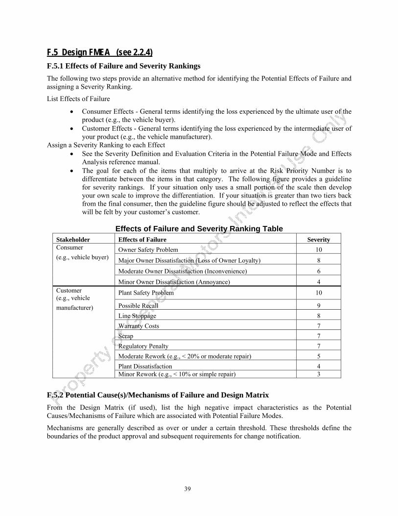
39
F.5 Design FMEA (see 2.2.4) F.5.1 Effects of Failure and Severity Rankings The following two steps provide an alternative method for identifying the Potential Effects of Failure and assigning a Severity Ranking.
List Effects of Failure
• Consumer Effects - General terms identifying the loss experienced by the ultimate user of the product (e.g., the vehicle buyer).
• Customer Effects - General terms identifying the loss experienced by the intermediate user of your product (e.g., the vehicle manufacturer).
Assign a Severity Ranking to each Effect • See the Severity Definition and Evaluation Criteria in the Potential Failure Mode and Effects
Analysis reference manual. • The goal for each of the items that multiply to arrive at the Risk Priority Number is to
differentiate between the items in that category. The following figure provides a guideline for severity rankings. If your situation only uses a small portion of the scale then develop your own scale to improve the differentiation. If your situation is greater than two tiers back from the final consumer, then the guideline figure should be adjusted to reflect the effects that will be felt by your customer’s customer.
Effects of Failure and Severity Ranking Table
Stakeholder Effects of Failure Severity Owner Safety Problem 10
Major Owner Dissatisfaction (Loss of Owner Loyalty) 8
Moderate Owner Dissatisfaction (Inconvenience) 6
Consumer (e.g., vehicle buyer)
Minor Owner Dissatisfaction (Annoyance) 4
Plant Safety Problem 10
Possible Recall 9 Line Stoppage 8 Warranty Costs 7 Scrap 7 Regulatory Penalty 7 Moderate Rework (e.g., < 20% or moderate repair) 5 Plant Dissatisfaction 4
Customer (e.g., vehicle manufacturer)
Minor Rework (e.g., < 10% or simple repair) 3
F.5.2 Potential Cause(s)/Mechanisms of Failure and Design Matrix From the Design Matrix (if used), list the high negative impact characteristics as the Potential Causes/Mechanisms of Failure which are associated with Potential Failure Modes.
Mechanisms are generally described as over or under a certain threshold. These thresholds define the boundaries of the product approval and subsequent requirements for change notification.
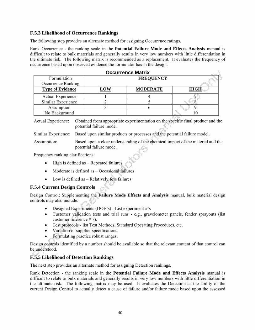
40
F.5.3 Likelihood of Occurrence Rankings The following step provides an alternate method for assigning Occurrence ratings.
Rank Occurrence - the ranking scale in the Potential Failure Mode and Effects Analysis manual is difficult to relate to bulk materials and generally results in very low numbers with little differentiation in the ultimate risk. The following matrix is recommended as a replacement. It evaluates the frequency of occurrence based upon observed evidence the formulator has in the design.
Occurrence Matrix Formulation
Occurrence Ranking FREQUENCY
Type of Evidence LOW MODERATE HIGHActual Experience 1 4 7 Similar Experience 2 5 8
Assumption 3 6 9 No Background 10
Actual Experience: Obtained from appropriate experimentation on the specific final product and the potential failure mode.
Similar Experience: Based upon similar products or processes and the potential failure model.
Assumption: Based upon a clear understanding of the chemical impact of the material and the potential failure mode.
Frequency ranking clarifications:
• High is defined as – Repeated failures
• Moderate is defined as – Occasional failures
• Low is defined as – Relatively few failures
F.5.4 Current Design Controls Design Control: Supplementing the Failure Mode Effects and Analysis manual, bulk material design controls may also include:
• Designed Experiments (DOE’s) - List experiment #’s • Customer validation tests and trial runs - e.g., gravelometer panels, fender sprayouts (list
customer reference #’s). • Test protocols - list Test Methods, Standard Operating Procedures, etc. • Variation of supplier specifications. • Formulating practice robust ranges.
Design controls identified by a number should be available so that the relevant content of that control can be understood.
F.5.5 Likelihood of Detection Rankings The next step provides an alternate method for assigning Detection rankings.
Rank Detection - the ranking scale in the Potential Failure Mode and Effects Analysis manual is difficult to relate to bulk materials and generally results in very low numbers with little differentiation in the ultimate risk. The following matrix may be used. It evaluates the Detection as the ability of the current Design Control to actually detect a cause of failure and/or failure mode based upon the assessed
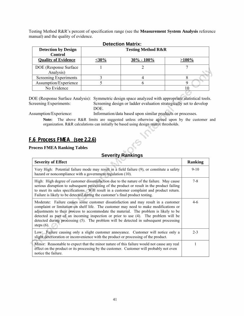
41
Testing Method R&R’s percent of specification range (see the Measurement System Analysis reference manual) and the quality of evidence.
Detection Matrix: Detection by Design
Control Testing Method R&R
Quality of Evidence <30% 30% - 100% >100%
DOE (Response Surface Analysis)
1 2 7
Screening Experiments 3 4 8 Assumption/Experience 5 6 9
No Evidence 10 DOE (Response Surface Analysis): Symmetric design space analyzed with appropriate statistical tools. Screening Experiments: Screening design or ladder evaluation strategically set to develop
DOE. Assumption/Experience: Information/data based upon similar products or processes.
Note: The above R&R limits are suggested unless otherwise agreed upon by the customer and organization. R&R calculations can initially be based using design matrix thresholds.
F.6 Process FMEA (see 2.2.6) Process FMEA Ranking Tables
Severity Rankings Severity of Effect Ranking
Very High: Potential failure mode may result in a field failure (9), or constitute a safety hazard or noncompliance with a government regulation (10).
9-10
High: High degree of customer dissatisfaction due to the nature of the failure. May cause serious disruption to subsequent processing of the product or result in the product failing to meet its sales specifications. Will result in a customer complaint and product return. Failure is likely to be detected during the customer’s final product testing.
7-8
Moderate: Failure causes some customer dissatisfaction and may result in a customer complaint or limitation on shelf life. The customer may need to make modifications or adjustments to their process to accommodate the material. The problem is likely to be detected as part of an incoming inspection or prior to use (4). The problem will be detected during processing (5). The problem will be detected in subsequent processing steps (6).
4-6
Low: Failure causing only a slight customer annoyance. Customer will notice only a slight deterioration or inconvenience with the product or processing of the product.
2-3
Minor: Reasonable to expect that the minor nature of this failure would not cause any real effect on the product or its processing by the customer. Customer will probably not even notice the failure.
1
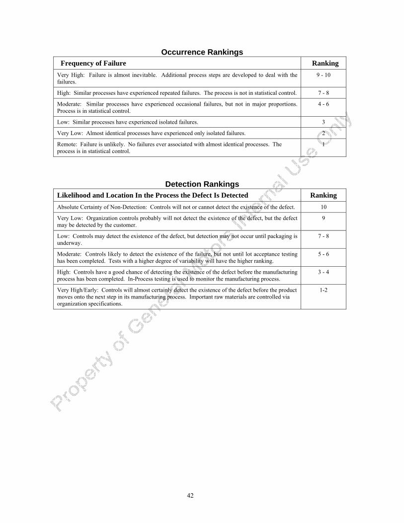
42
Occurrence Rankings Frequency of Failure Ranking
Very High: Failure is almost inevitable. Additional process steps are developed to deal with the failures.
9 - 10
High: Similar processes have experienced repeated failures. The process is not in statistical control. 7 - 8
Moderate: Similar processes have experienced occasional failures, but not in major proportions. Process is in statistical control.
4 - 6
Low: Similar processes have experienced isolated failures. 3
Very Low: Almost identical processes have experienced only isolated failures. 2
Remote: Failure is unlikely. No failures ever associated with almost identical processes. The process is in statistical control.
1
Detection Rankings Likelihood and Location In the Process the Defect Is Detected Ranking Absolute Certainty of Non-Detection: Controls will not or cannot detect the existence of the defect. 10
Very Low: Organization controls probably will not detect the existence of the defect, but the defect may be detected by the customer.
9
Low: Controls may detect the existence of the defect, but detection may not occur until packaging is underway.
7 - 8
Moderate: Controls likely to detect the existence of the failure, but not until lot acceptance testing has been completed. Tests with a higher degree of variability will have the higher ranking.
5 - 6
High: Controls have a good chance of detecting the existence of the defect before the manufacturing process has been completed. In-Process testing is used to monitor the manufacturing process.
3 - 4
Very High/Early: Controls will almost certainly detect the existence of the defect before the product moves onto the next step in its manufacturing process. Important raw materials are controlled via organization specifications.
1-2
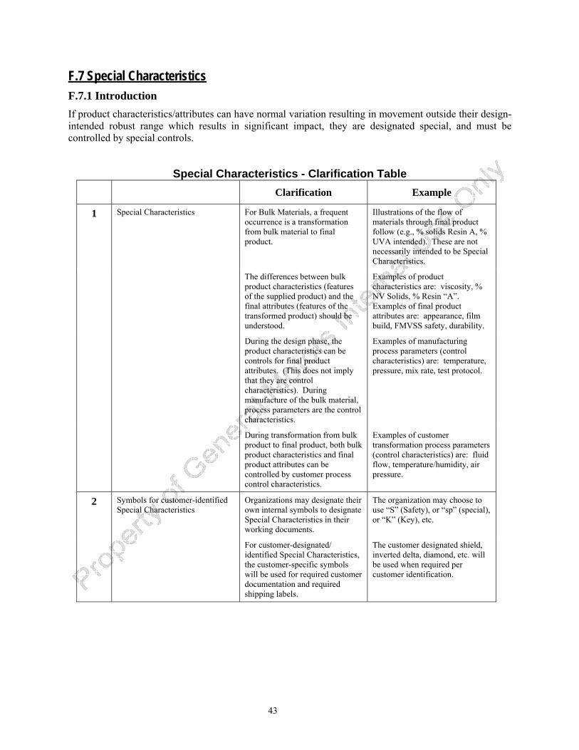
43
F.7 Special Characteristics F.7.1 Introduction If product characteristics/attributes can have normal variation resulting in movement outside their design-intended robust range which results in significant impact, they are designated special, and must be controlled by special controls.
Special Characteristics - Clarification Table Clarification Example
1 Special Characteristics For Bulk Materials, a frequent occurrence is a transformation from bulk material to final product.
Illustrations of the flow of materials through final product follow (e.g., % solids Resin A, % UVA intended). These are not necessarily intended to be Special Characteristics.
The differences between bulk product characteristics (features of the supplied product) and the final attributes (features of the transformed product) should be understood.
Examples of product characteristics are: viscosity, % NV Solids, % Resin “A”. Examples of final product attributes are: appearance, film build, FMVSS safety, durability.
During the design phase, the product characteristics can be controls for final product attributes. (This does not imply that they are control characteristics). During manufacture of the bulk material, process parameters are the control characteristics.
Examples of manufacturing process parameters (control characteristics) are: temperature, pressure, mix rate, test protocol.
During transformation from bulk product to final product, both bulk product characteristics and final product attributes can be controlled by customer process control characteristics.
Examples of customer transformation process parameters (control characteristics) are: fluid flow, temperature/humidity, air pressure.
2 Symbols for customer-identified Special Characteristics
Organizations may designate their own internal symbols to designate Special Characteristics in their working documents.
The organization may choose to use “S” (Safety), or “sp” (special), or “K” (Key), etc.
For customer-designated/ identified Special Characteristics, the customer-specific symbols will be used for required customer documentation and required shipping labels.
The customer designated shield, inverted delta, diamond, etc. will be used when required per customer identification.
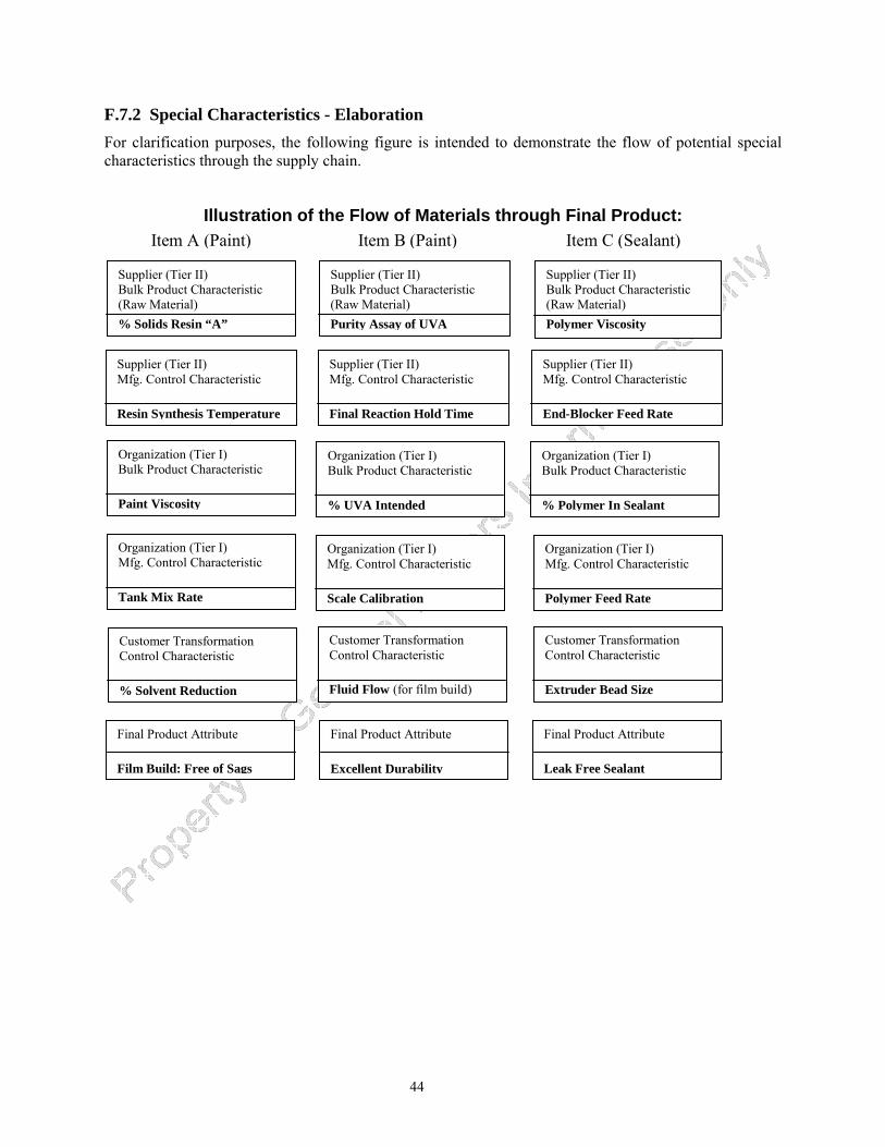
44
Illustration of the Flow of Materials through Final Product:
F.7.2 Special Characteristics - Elaboration For clarification purposes, the following figure is intended to demonstrate the flow of potential special characteristics through the supply chain.
Supplier (Tier II) Bulk Product Characteristic (Raw Material) % Solids Resin “A”
Supplier (Tier II) Bulk Product Characteristic (Raw Material) Purity Assay of UVA
Supplier (Tier II) Bulk Product Characteristic (Raw Material) Polymer Viscosity
Supplier (Tier II) Mfg. Control Characteristic Resin Synthesis Temperature
Supplier (Tier II) Mfg. Control Characteristic Final Reaction Hold Time
Supplier (Tier II) Mfg. Control Characteristic End-Blocker Feed Rate
Organization (Tier I) Bulk Product Characteristic % UVA Intended
Organization (Tier I) Bulk Product Characteristic % Polymer In Sealant
Organization (Tier I) Bulk Product Characteristic Paint Viscosity
Organization (Tier I) Mfg. Control Characteristic Tank Mix Rate
Organization (Tier I) Mfg. Control Characteristic Scale Calibration
Organization (Tier I) Mfg. Control Characteristic Polymer Feed Rate
Customer Transformation Control Characteristic % Solvent Reduction
Customer Transformation Control Characteristic Fluid Flow (for film build)
Customer Transformation Control Characteristic Extruder Bead Size
Final Product Attribute Film Build: Free of Sags
Final Product Attribute Excellent Durability
Final Product Attribute Leak Free Sealant
Item A (Paint) Item B (Paint) Item C (Sealant)
45
F.8 Control Plan (see 2.2.7) F.8.1 Introduction The Bulk Material Control Plan serves as a mechanism to:
• Highlight Special Product/Process Characteristics and their controls
• Link together sources of control methods, instructions and specification/tolerance limits and reference them in one document
Additionally, this control plan is not intended to recreate specification and/or tolerance limits that exist in other control sources such as batch tickets, work instructions and testing protocols.
F.8.2 Control Plan - Elaboration Refer to the customer’s specified control plan format (e.g., that found in the Advanced Product Quality Planning and Control Plan reference manual).
• Prototype (when required) - A listing of tests, evaluations and their associated specifications/tolerances used to assess an experimental or developmental formulation. This may be the only control plan that is product specific.
• Pre-launch - Documentation of the product/process control characteristics, process controls affecting Special Characteristics, associated tests, and measurement systems employed during product scale up and prior to normal production.
• Production - Documentation of the product/process control characteristics, process controls affecting Special Characteristics, associated tests, and measurement systems employed during normal production. Additional items may be included at the Organization’s discretion.
Pre-launch and production control plans may be applied to a family of products or specific processes.
46
F.9 Measurement System Analysis (MSA) Studies (see 2.2.8) Bulk materials often require further processing after sampling in order to make a measurement.
Measurements are often destructive in nature and this prevents retesting the same sample.
Measurement variability is often much larger for properties important in the process industries (e.g., viscosity and purity) than it is for properties measured in mechanical industries (e.g., dimensions). Measurement may account for 50% or more of the total observed variation.
Standardized test methods (e.g., ASTM, AMS, ISO) are often followed. The organization need not re-verify bias, linearity, stability, and Gage R&R.
MSA studies are not required where standardized tests are used, however it is still important for the organization to understand the measurement component of variation in the test methods used.
Customer agreement on the actual requirements for MSA for either non-standard test methods or “new-to-supplier” test methods should be obtained during the planning phase.
Any MSA studies should be applied to each test method associated with Special Characteristics, and not to each individual product measured by the test method. Therefore, the MSA studies should be conducted as broadly as possible across all products which use a particular test method. If the resulting variability is unacceptable, then either the studies should be conducted on a narrower class of products or action should be taken to improve the test method.
F.10 Initial Process Studies For Special Characteristics (see 2.2.11) The manufacture of bulk materials consists of industries which span a variety of production processes, from high volume products to specialty products produced in small quantities no more than once or twice per year. Often the production process is completed or already in place before sufficient samples can be tested. By the time the product is made again, personnel and/or equipment may have changed. Also, these processes have numerous input variables, many control variables, and a variety of product variations. There are non-linearities – meaning for example that doubling the change in a particular input does not necessarily double the change in the output. The effects and relationships between all these variables and controls are also not usually known without error. Multiple processes are usually interconnected, sometimes with feedback loops. There are also timing considerations and delays in reaction time. Further, measurements of component variables are generally less precise than measurements of component parts, such that in many cases correlated variables must be used.
47
F.11 Master Sample (see 2.2.15) F.11.1 Introduction The requirements for master sample or equivalent shall be agreed by the customer and organization.
Physical Sample: Some bulk materials are stable and unchanging over an extended period of time (e.g., they do not significantly change physical or chemical composition, if properly stored, for decades). In this case, a physical sample will serve as a Master Sample.
Analytical Sample Record: Other bulk materials change with time, but can be precisely quantified by appropriate analytical techniques. In this case the analytical record (e.g., Ultra-Violet or Infra-Red spectra “fingerprint,” Atomic Absorption or Gas Chromatographic-Mass Spectrometric analysis) is an appropriate Master Sample.
Manufacturing Sample Record: When bulk materials can not be distinctly identified or change over time, a manufacturing sample record should be generated. The record should include the information required to manufacture a “normal production size” run (lot or batch), according to the final “Production Control Plan” supporting the PSW. This record provides an “audit trail” to the information which may be stored in various documents and or electronic systems. The following is the basic information suggested to accomplish this task:
• The quantity of product produced. • The important performance results. • The raw materials utilized (including manufacturer, Lot # and important properties records). • The critical equipment required to manufacture the bulk material. • Analytical sample records, as described above, on the material as produced. • Batch ticket used to manufacture the bulk material.
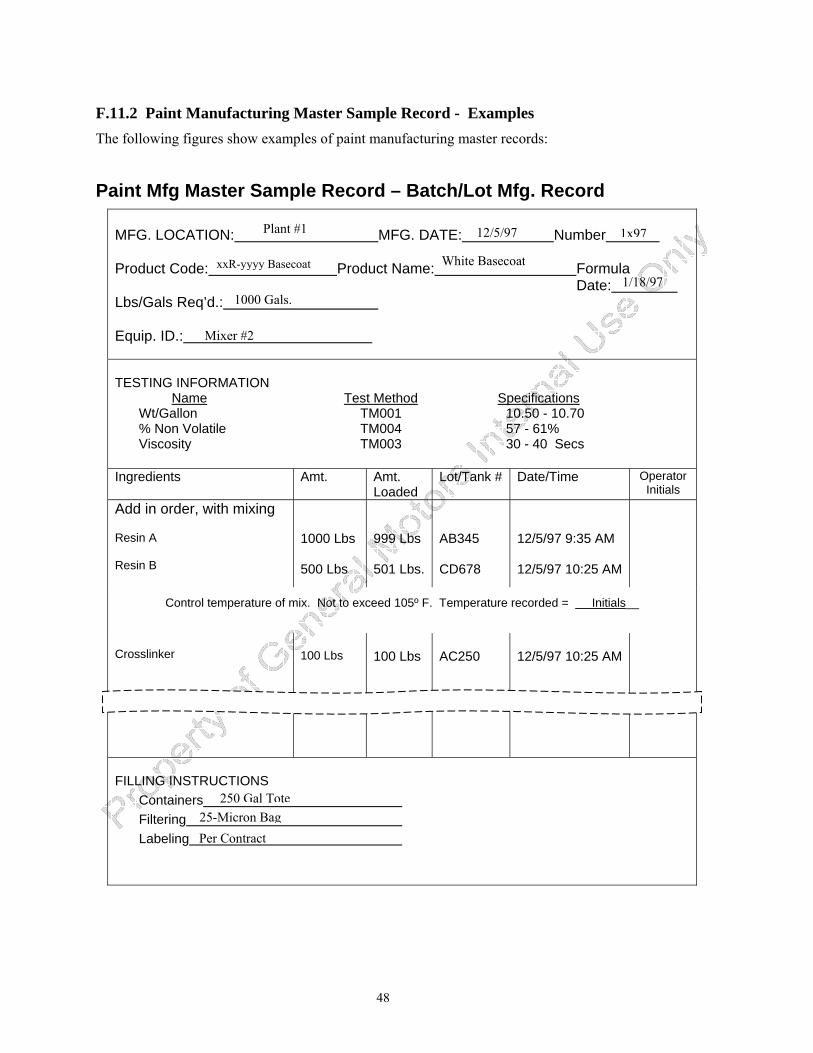
48
F.11.2 Paint Manufacturing Master Sample Record - Examples The following figures show examples of paint manufacturing master records:
Paint Mfg Master Sample Record – Batch/Lot Mfg. Record MFG. LOCATION: MFG. DATE: Number Product Code: Product Name: Formula Date: Lbs/Gals Req’d.: Equip. ID.:
TESTING INFORMATION Name Test Method Specifications
Plant #1 1x9712/5/97
White BasecoatxxR-yyyy Basecoat 1/18/97
1000 Gals.
Mixer #2
Wt/Gallon TM001 10.50 - 10.70 % Non Volatile TM004 57 - 61% Viscosity TM003 30 - 40 Secs Ingredients Amt. Amt.
Loaded Lot/Tank # Date/Time Operator
Initials Add in order, with mixing Resin A Resin B
1000 Lbs 500 Lbs
999 Lbs 501 Lbs.
AB345 CD678
12/5/97 9:35 AM 12/5/97 10:25 AM
Control temperature of mix. Not to exceed 105º F. Temperature recorded = Initials__
Crosslinker
100 Lbs
100 Lbs
12/5/97 10:25 AM
AC250
FILLING INSTRUCTIONS Containers Filtering Labeling
250 Gal Tote 25-Micron Bag Per Contract
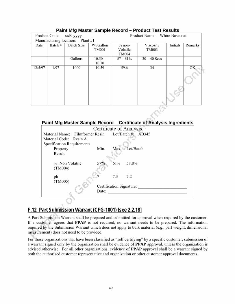
49
Paint Mfg Master Sample Record – Product Test Results Product Code: xxR-yyyy Product Name: White Basecoat Manufacturing location: Plant #1 Date Batch # Batch Size Wt/Gallon
TM001 % non-Volatile TM004
Viscosity TM003
Initials Remarks
Gallons 10.50 – 10.70
57 – 61% 30 – 40 Secs
12/5/97 1/97 1000 10.59 59.6 34 OK
Paint Mfg Master Sample Record – Certificate of Analysis Ingredients Certificate of Analysis
Material Name: Filmformer Resin Lot/Batch #: AB345 Material Code: Resin A Specification Requirements Property Min. Max Lot/Batch Result % Non Volatile 57% 61% 58.8% (TM004) ph 7 7.3 7.2 (TM005) Certification Signature: _______________________ Date: _____________________________________
F.12 Part Submission Warrant (CFG-1001) [see 2.2.18] A Part Submission Warrant shall be prepared and submitted for approval when required by the customer. If a customer agrees that PPAP is not required, no warrant needs to be prepared. The information required by the Submission Warrant which does not apply to bulk material (e.g., part weight, dimensional measurement) does not need to be provided.
For those organizations that have been classified as “self certifying” by a specific customer, submission of a warrant signed only by the organization shall be evidence of PPAP approval, unless the organization is advised otherwise. For all other organizations, evidence of PPAP approval shall be a warrant signed by both the authorized customer representative and organization or other customer approval documents.
50
F.13 Interim Approval (see 5.2.2) Most products will achieve approval prior to initial use. In cases where approval cannot be obtained, a “Bulk Material Interim Approval” may be granted. A form is shown on the facing page; other forms may be used.
COMPLETION OF THE BULK MATERIAL INTERIM APPROVAL FORM 1. ORGANIZATION NAME: Name assigned to Organization’s manufacturing location.
2. PRODUCT NAME: The Organization’s designated name for the product—as identified in the Customer’s Engineering Release Documents.
3. SUPPLIER/VENDOR CODE: Code (DUNS number or equivalent) assigned to the manufacturing location as shown on the Customer’s purchase order.
4. ENG. SPEC.: Customer’s identified Specification through which the product is approved and released.
5. MANUF. SITE: Physical address of the manufacturing location as shown on the Customer’s purchase order.
6. PART #: Customer’s Part Number.
7. ENG. CHANGE #: Formula Revision Level or number identifying the formula.
8. FORMULA DATE: Engineering Release Date of the formula identified in item #7.
9. RECEIVED DATE: Customer Use Only.
10. RECEIVED BY: Customer Use Only (Customer Representative).
11. SUBMISSION LEVEL: Submission Level (1-5) that Organization is required to submit to as defined by the Customer.
12. EXPIRATION DATE: Date that the Interim Approval expires.
13. TRACKING CODE: Customer Use Only.
14. RE-SUBMISSION DATE: Date organization will resubmit for production approval.
15. STATUS: For each item, enter appropriate code (NR — Not Required, A — Approved, I — Interim).
16. SPECIFIC QUANTITY OF MATERIAL AUTHORIZED: Utilized when Interim Approval specifies a specific quantity of volume of product.
17. PRODUCTION TRIAL AUTHORIZATION: Customer’s Engineering Release authorizing the use of the product in the Customer’s facility.
18. REASON(S) FOR INTERIM APPROVAL: Indicate reason for Interim Request.
19. ISSUES TO BE RESOLVED, EXPECTED COMPLETION DATE: For each item marked as “I” in #15, provide explanatory details regarding problem issues and furnish a date for problem resolution.
20. ACTIONS TO BE ACCOMPLISHED DURING INTERIM PERIOD, EFFECTIVE DATE: What is being done to ensure defective product is contained, date when the action was implemented and Exit Criteria necessary to end need for continuing the action or its individual elements.
21. PROGRESS REVIEW DATE: Update on progress of problem resolution, generally the midpoint from issuance to expiration of the interim period.
22. DATE MATERIAL DUE TO PLANT: Date material is due to Customer’s site.
23. WHAT ACTIONS ARE TAKING PLACE TO ENSURE THAT FUTURE SUBMISSIONS WILL CONFORM TO ALL PPAP REQUIREMENTS BY THE SAMPLE PROMISE DATE? Why won’t this happen again?
24. ORGANIZATION: Responsible and Authorized Organization official to ensure compliance to the above mentioned actions and dates.
25. PRODUCT ENG.: Product Engineer’s signature, printed name, phone number, and date.
26. MATERIALS ENG.: Material Engineer’s signature, printed name, phone number, and date.
27. QUALITY ENG.: Quality Engineer’s signature, printed name, phone number, and date.
28. INTERIM APPROVAL NUMBER: Customer Use Only.
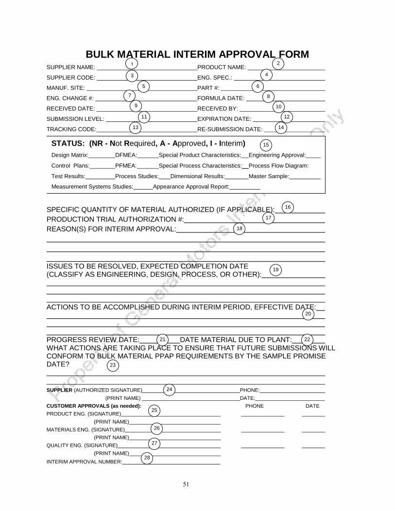
51
BULK MATERIAL INTERIM APPROVAL FORM SUPPLIER NAME: PRODUCT NAME:
SUPPLIER CODE: ENG. SPEC.:
MANUF. SITE: PART #:
ENG. CHANGE #: FORMULA DATE:
RECEIVED DATE: RECEIVED BY:
SUBMISSION LEVEL: EXPIRATION DATE:
TRACKING CODE: RE-SUBMISSION DATE: SPECIFIC QUANTITY OF MATERIAL AUTHORIZED (IF APPLICABLE): PRODUCTION TRIAL AUTHORIZATION #: REASON(S) FOR INTERIM APPROVAL: ISSUES TO BE RESOLVED, EXPECTED COMPLETION DATE (CLASSIFY AS ENGINEERING, DESIGN, PROCESS, OR OTHER): ACTIONS TO BE ACCOMPLISHED DURING INTERIM PERIOD, EFFECTIVE DATE: PROGRESS REVIEW DATE: DATE MATERIAL DUE TO PLANT: WHAT ACTIONS ARE TAKING PLACE TO ENSURE THAT FUTURE SUBMISSIONS WILL CONFORM TO BULK MATERIAL PPAP REQUIREMENTS BY THE SAMPLE PROMISE DATE? SUPPLIER (AUTHORIZED SIGNATURE) PHONE: (PRINT NAME) DATE: CUSTOMER APPROVALS (as needed): PHONE DATE PRODUCT ENG. (SIGNATURE) (PRINT NAME) MATERIALS ENG. (SIGNATURE) (PRINT NAME) QUALITY ENG. (SIGNATURE) (PRINT NAME) INTERIM APPROVAL NUMBER:
STATUS: (NR - Not Required, A - Approved, I - Interim)Design Matrix: DFMEA: Special Product Characteristics: Engineering Approval:
Control Plans: PFMEA: Special Process Characteristics:__ Process Flow Diagram:
Test Results: Process Studies: Dimensional Results: Master Sample:
Measurement Systems Studies: Appearance Approval Report:
3 4
5 6
7 8
9 10
11 12
13 14
15
16
17
18
19
20
21 22
23
24
25
26
27
28
2 1
52
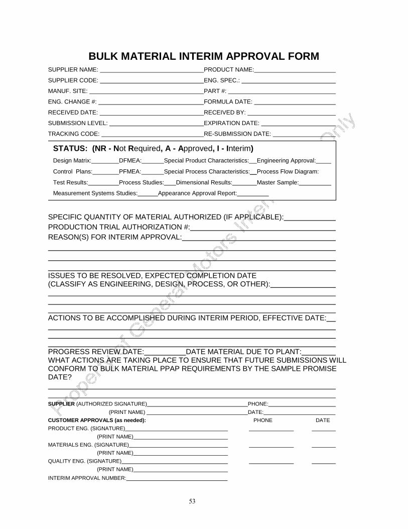
53
BULK MATERIAL INTERIM APPROVAL FORM SUPPLIER NAME: PRODUCT NAME:
SUPPLIER CODE: ENG. SPEC.:
MANUF. SITE: PART #:
ENG. CHANGE #: FORMULA DATE:
RECEIVED DATE: RECEIVED BY:
SUBMISSION LEVEL: EXPIRATION DATE:
TRACKING CODE: RE-SUBMISSION DATE: SPECIFIC QUANTITY OF MATERIAL AUTHORIZED (IF APPLICABLE): PRODUCTION TRIAL AUTHORIZATION #: REASON(S) FOR INTERIM APPROVAL: ISSUES TO BE RESOLVED, EXPECTED COMPLETION DATE (CLASSIFY AS ENGINEERING, DESIGN, PROCESS, OR OTHER): ACTIONS TO BE ACCOMPLISHED DURING INTERIM PERIOD, EFFECTIVE DATE: PROGRESS REVIEW DATE: DATE MATERIAL DUE TO PLANT: WHAT ACTIONS ARE TAKING PLACE TO ENSURE THAT FUTURE SUBMISSIONS WILL CONFORM TO BULK MATERIAL PPAP REQUIREMENTS BY THE SAMPLE PROMISE DATE? SUPPLIER (AUTHORIZED SIGNATURE) PHONE: (PRINT NAME) DATE: CUSTOMER APPROVALS (as needed): PHONE DATE PRODUCT ENG. (SIGNATURE) (PRINT NAME) MATERIALS ENG. (SIGNATURE) (PRINT NAME) QUALITY ENG. (SIGNATURE) (PRINT NAME) INTERIM APPROVAL NUMBER:
STATUS: (NR - Not Required, A - Approved, I - Interim)Design Matrix: DFMEA: Special Product Characteristics: Engineering Approval:
Control Plans: PFMEA: Special Process Characteristics:__ Process Flow Diagram:
Test Results: Process Studies: Dimensional Results: Master Sample:
Measurement Systems Studies: Appearance Approval Report:
54
55
F.14 Customer Plant Connection
F.14.1 Customer’s Responsibilities The customer plant connection is a shared responsibility between the organization supplying bulk material and the customer. This connection defines the interaction of specific customer plant processing steps with Special Characteristics and final product attributes of the bulk material. This interaction is especially significant when bulk materials undergo chemical or physical transformation(s). Three key components of the Customer Plant Connection are the development of a Customer Process Matrix (SEE FOLLOWING EXAMPLE), determination of Special Characteristics from the Customer Process Matrix, and the preparation of a Control Plan which systematically directs corrective actions. For bulk materials, conducting the steps outlined in this “Customer Plant Connection” is highly recommended.
NOTE: It is not the intent of PPAP to compromise proprietary information.
F.14.2 Customer Plant Connection – Clarification The following is applicable to materials that are transformed from bulk (e.g., wet can of paint) to final product (e.g., cured paint film). This may not be applicable to all bulk materials (i.e. washer fluid, engine oil, etc.). It is recognized by the organization that it is their responsibility to deliver the product to the customer with the characteristics of the bulk material per organization and customer agreement.
The impact of the transformation of bulk materials by the customer plant on final product attributes may be accounted for in the customer’s application process. During the transformation from bulk product to final product, both bulk product characteristics and final product attributes may be impacted by customer process controls.
PPAP does not require a Process FMEA or Control Plan for the customer process. Since the product is frequently two products (bulk and finished), there is a shared responsibility for the final product attribute. For example, percent solids and viscosity of a bulk coating which impacts the final coating’s film build attribute, may be affected by the customer’s mix room percent solvent reduction. The percent reduction process parameter may therefore be controlled to aid in control of film build. The process steps at customer plants may be matrixed versus the Special Characteristics (determined jointly by the organization and the customer). Where high impact is evident, those process steps may be analyzed by the Process FMEA methodology.
The Special Characteristics may then be determined, and be included in a Control Plan for the customer process. These special control characteristic items may be monitored and continuously improved.
F.14.3 Customer Plant Connection - Guidelines The following is a recommended set of guidelines for the customer plant when implementing process controls for bulk materials.
1. Assemble cross-functional teams of customer personnel for each customer process area. Include appropriate organization representatives on each team.
2. Select Champions for each team - these are the customer process owners (i.e., chief process engineer, area supervisor, etc.).
3. Define critical customer handling, application steps and process parameters in each area.
4. Review the organization’s Design Matrix and Design FMEA items for application functions which have been designated as Special Characteristics. Also review the desired final product attributes for items needing control.
5. From #4, develop a list of Special Characteristics and Attributes.
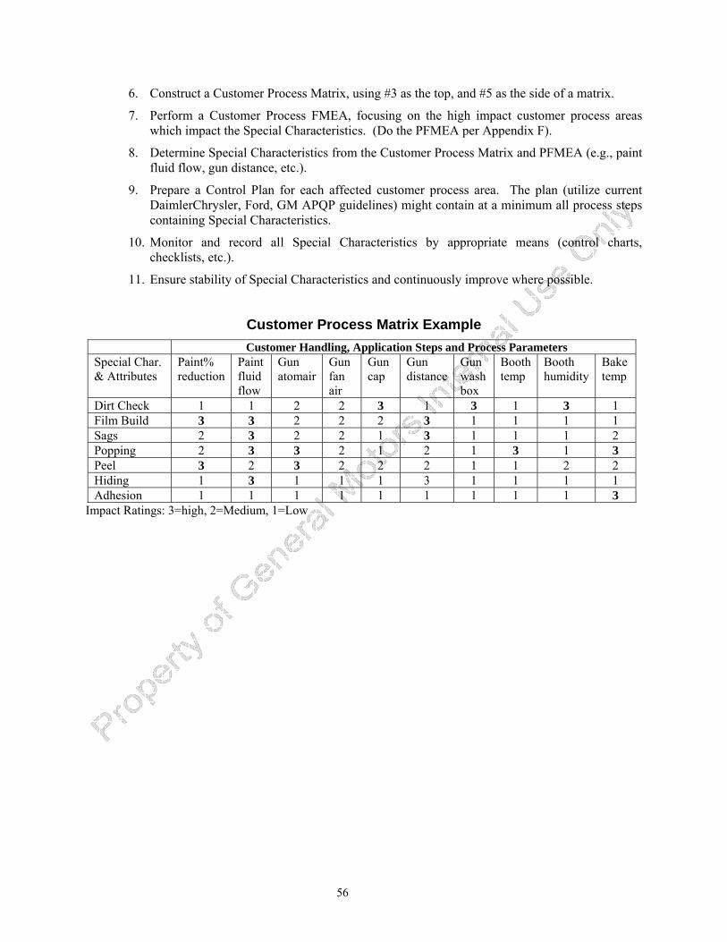
56
6. Construct a Customer Process Matrix, using #3 as the top, and #5 as the side of a matrix.
7. Perform a Customer Process FMEA, focusing on the high impact customer process areas which impact the Special Characteristics. (Do the PFMEA per Appendix F).
8. Determine Special Characteristics from the Customer Process Matrix and PFMEA (e.g., paint fluid flow, gun distance, etc.).
9. Prepare a Control Plan for each affected customer process area. The plan (utilize current DaimlerChrysler, Ford, GM APQP guidelines) might contain at a minimum all process steps containing Special Characteristics.
10. Monitor and record all Special Characteristics by appropriate means (control charts, checklists, etc.).
11. Ensure stability of Special Characteristics and continuously improve where possible.
Customer Process Matrix Example Customer Handling, Application Steps and Process Parameters
Special Char. & Attributes
Paint% reduction
Paint fluid flow
Gun atomair
Gun fan air
Gun cap
Gun distance
Gun wash box
Booth temp
Booth humidity
Bake temp
Dirt Check 1 1 2 2 3 1 3 1 3 1 Film Build 3 3 2 2 2 3 1 1 1 1 Sags 2 3 2 2 1 3 1 1 1 2 Popping 2 3 3 2 1 2 1 3 1 3 Peel 3 2 3 2 2 2 1 1 2 2 Hiding 1 3 1 1 1 3 1 1 1 1 Adhesion 1 1 1 1 1 1 1 1 1 3
Impact Ratings: 3=high, 2=Medium, 1=Low
57
Appendix G – Tires - Specific Requirements
G.1 Introduction and Applicability An organization supplying tires shall comply with the requirements of PPAP.
This Appendix is to be used as guidance for clarification of requirements unless otherwise specified by the authorized OEM customer representative.
Performance testing, based upon design requirements used by each OEM to select tire construction (technical approval), reduces the need to repeat all tests during PPAP. Specific PPAP confirmation tests are specified by each OEM.
G.2 Guidelines for PPAP Requirements (Reference Section 2.1) Significant Production Run (2.1) Unless otherwise specified by the OEM, the size of the production run for the PPAP parts is a minimum of 30 tires.
NOTE 1: The above definition applies to all uses of “significant production run” within PPAP. NOTE 2: The typical development of a new tire design involves multiple builds of a small quantity of tires. Most designs are basic to the organization’s process. For the tire industry, PPAP is typically completed with an initial mold or molds, and well in advance of customer requirements for large volume production. NOTE 3: The PPAP for the tire industry typically is derived from 1 to 8 hours of tire curing from the approved production process as specified in the organization’s control plan.
PPAP is not required for additional molds that are brought on line in the approved production process. All additional molds shall be certified by the organization’s internal certification criteria and documentation.
NOTE 4: For tires, tooling is defined as the tire mold. This definition of tooling applies to all uses of “tooling” within PPAP.
Material Test Results (Reference 2.2.10.1) Testing is applicable only to finished tires and not to raw materials. Tire industry practice does not require chemical, physical, or metallurgical testing. Material test results are not required for PPAP.
Special Characteristics (Reference 2.2.11.1) Tire uniformity (force variation) and balance are designated Special Characteristics.
Appearance Approval Report (AAR) (Reference 2.2.13) The AAR requirement is not applicable.
Master Sample (see 2.2.15 and 2.2.9) Master samples are not retained.
Process Flow Diagrams See PPAP 2.2.5.
58
Checking Aids (see 2.2.16) Checking aids are not required.
PPAP Submission Warrant (see 2.2.18) Reporting of multiple cavities, molds, lines, etc. on the PSW is not required for tires.
Part Weight (Mass) (Reference 2.2.18.1) PPAP tires are weighed to two (2) significant decimals (xx.xx). The average is reported on the PSW to four (4) decimals (xx.xxxx).
G.3 Submission to Customer - Levels of Evidence (Reference Section 4 ) Retention/Submission Requirements (Reference Table 4.2) Records of items submitted (S) and retained (R) are maintained at appropriate locations designated by the organization.
59
Appendix H – Truck Industry - Specific Requirements
Introduction An organization supplying to subscribing truck OEMs shall comply with the requirements in this Appendix or use guidance herein for clarification of PPAP. The requirements in this Appendix are minimums and may be supplemented at the discretion of the organization and/or the customer.
Applicability (see Page 1) The following additional requirements are added:
• The Customer has the right to request a PPAP at any time to re-qualify a production component.
• Feature Base Process or Part Number Generated components are PPAP qualified using the highest content configuration to qualify the master part number. All other configurations may be approved with the submission of a PSW linking the new part number with the master part number.
• For bulk material and standard catalog parts, the organization shall formally qualify their product to their design record and submit a PSW when requested by the customer.
Significant Production Run (see 2.1) It is important that adequate quantities of parts be manufactured during this run to confirm the quality and capability of production process at rate prior to full production. It is recognized that in low volume applications, sample sizes as small as 30 pieces may be utilized for preliminary process capability studies.
When performing the Significant Production Run, all aspects of variability within the production process should be considered and tested where practicable, e.g., set-up variability or other potential process related issues identified within the PFMEA.
Sample sizes must be discussed and agreed to early in the APQP process. If projected volumes are so low that 30 samples are not attainable prior to production, interim PPAP approval may be granted. A dimensional report with 100% inspection on special characteristics is required during the interim period. Once the 30 consecutive production samples are produced, measured, and the quality index calculated and accepted, then the interim approval is changed to approved.
Dimensional Results (see 2.2.9) The organization shall submit, as part of the PPAP package, a copy of the drawing with each dimension, test, and or specification identified with a unique number. These unique numbers shall be entered onto the dimensional or test results sheet as applicable, and actual results entered onto the appropriate sheets. The organization shall also identify the print zone for each numbered characteristic as applicable.
60
Material Test (see 2.2.10.1) The organization shall also submit a completed Design Verification Plan and Report that summarizes appropriate performance and functional test results.
Quality Indices (see 2.2.11.2) When the customer specifies special characteristics and the estimated annual usage is less than 500 pieces, the organization shall document in their control plan that they will either:
• perform 100% inspection and record the results
or
• conduct an initial process capability study with a minimum of 30 production pieces and maintain SPC control charts of the characteristics during production.
For special characteristics that can be studied using variables data, the organization shall utilize one of the following techniques to study the stability of the process:
• X-Bar and R Charts, n=5, plot minimum 6 subgroups
or
• Individual X - Moving Range, plot minimum 30 data points
When performing the initial process study, data shall be plotted from consecutive parts taken from the production trial run. These studies could be augmented or replaced by long-term results from the same or similar process run on the same equipment with prior customer concurrence.
Master Sample (see 2.2.15) The master sample shall be retained after PPAP approval when specified by the customer.
Part Submission Warrant (see 2.2.18) When specified by the customer, organizations shall use the Truck Industry PSW (see the Truck Industry PSW Form that follows).
Part Weight (mass) (see 2.2.18.1) The organization may record the part weight of the part submitted on the PSW measured and expressed in kilograms to four significant figures (e.g., 1000Kg, 100.0Kg, 10.00Kg, and 1.000Kg) unless otherwise specified by the customer. To determine part weight, the organization shall individually weigh ten randomly selected parts, and calculate and report the average weight. At least one part shall be measured from each cavity, tool, line, or process used in product realization.
Customer Notification (see 3.1) The organization shall notify the customer of any planned design and process changes. The customer may subsequently elect to require a submission for PPAP approval. Organizations supplying to subscribing truck OEMs are required to complete the Product Process Change notification form to advise of forthcoming process or proprietary product changes.
61
Completion of the Part Submission Warrant PART INFORMATION1. Part Name: Engineering released finished end item part name. 2. Customer Part Number(s): Engineering released finished end item part number. 3. Part Revision Level: if applicable. 4. Tool Purchase Order Number: if applicable. 5. Engineering Drawing Change Level & Approval Date: Show change level and date for submission. 6. Additional Engineering Changes: Include all authorized engineering change documents and
approval dates not yet incorporated on the drawing but which are incorporated in the part. 7. Shown on Drawing Number: The design record that specifies the customer part number being
submitted. 8. Purchase Order Number: Enter this number as found on the purchase order. 9. Part weight: Enter the actual weight in kilograms to four significant places. 10. Checking Aid Number: Enter the checking aid number, if one is used for dimensional inspection,
and 11. Its Engineering Change Level and Approval Date. ORGANIZATION MANUFACTURING INFORMATION12. Organization Name and Code: Show the code assigned to the manufacturing location on the
purchase order. 13. Organization Manufacturing Address: Show the complete address of the location where the product
was manufactured. SUBMISSION INFORMATION14. Customer Name/Division: Show the corporate name and division or operations group. 15. Contact Name: Enter the name of your customer contact. 16. Application: Enter the model year, vehicle name, or engine, transmission, etc. 17. Check the appropriate box to indicate Substances of Concern/ISO marking reporting. REASON FOR SUBMISSION18. Check the appropriate box. Add explanatory details in the “other” section. REQUESTED SUBMISSION LEVEL19. Identify the submission level requested by your customer. Check the submission items if a level 4 is
requested. DECLARATION20. Explanation/Comments: Provide any explanatory details on the submission results; additional
information may be attached as appropriate. 21. Enter the number or code that identifies the specific mold, cavity, and/or production process used to
manufacture the sample parts. 22. The responsible supplier official, after verifying that the results show conformance to all customer
requirements and that all required documentation is available, shall approve the declaration and provide Title, Phone Number, Email Address, and Fax Number.
FOR CUSTOMER USE ONLY: Leave blank.
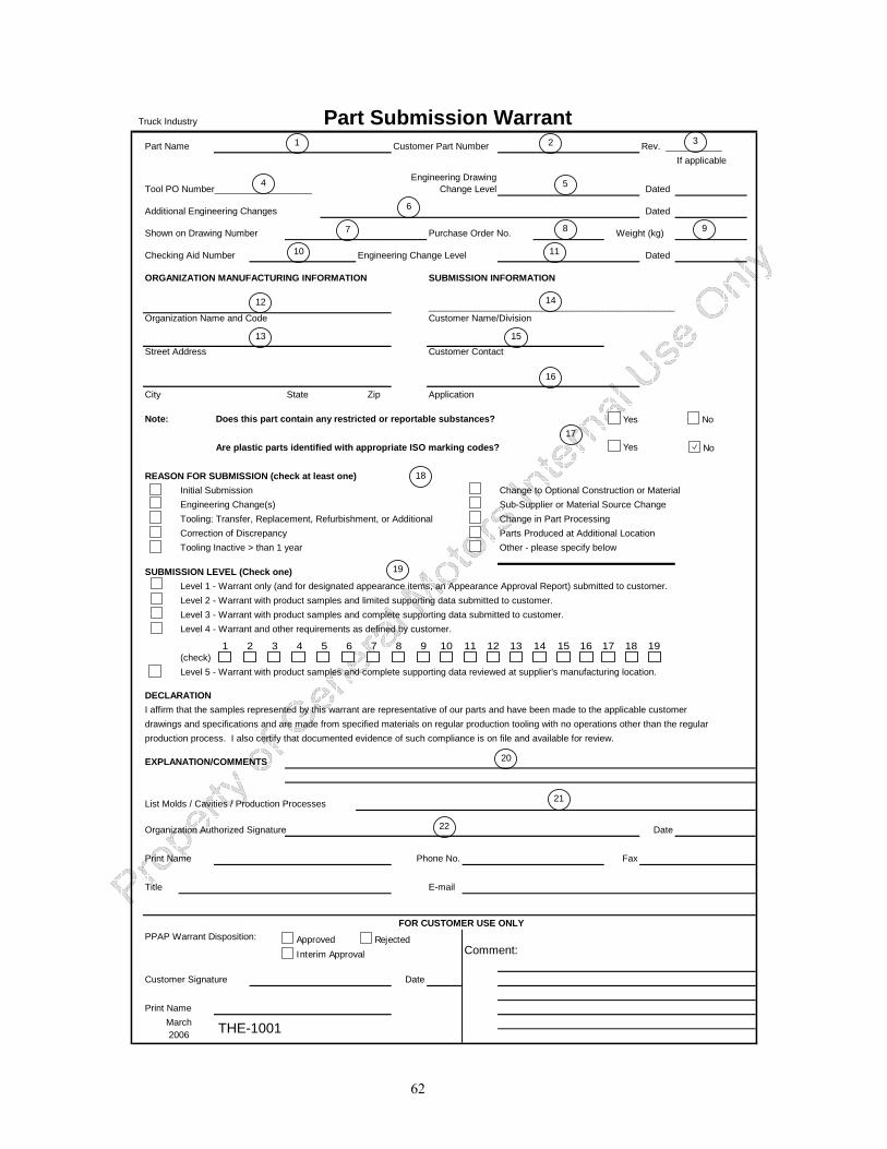
62
Truck Industry Part Submission WarrantPart Name Customer Part Number Rev. ___________
If applicable
Dated
Additional Engineering Changes Dated
Shown on Drawing Number Purchase Order No. Weight (kg)
Checking Aid Number Engineering Change Level Dated
ORGANIZATION MANUFACTURING INFORMATION SUBMISSION INFORMATION
________________________________________________Organization Name and Code Customer Name/Division
Street Address Customer Contact
City State Zip Application
Note: Does this part contain any restricted or reportable substances?
Are plastic parts identified with appropriate ISO marking codes?
REASON FOR SUBMISSION (check at least one)Initial Submission Change to Optional Construction or MaterialEngineering Change(s) Sub-Supplier or Material Source ChangeTooling: Transfer, Replacement, Refurbishment, or Additional Change in Part ProcessingCorrection of Discrepancy Parts Produced at Additional LocationTooling Inactive > than 1 year Other - please specify below
SUBMISSION LEVEL (Check one)Level 1 - Warrant only (and for designated appearance items, an Appearance Approval Report) submitted to customer.Level 2 - Warrant with product samples and limited supporting data submitted to customer.Level 3 - Warrant with product samples and complete supporting data submitted to customer.Level 4 - Warrant and other requirements as defined by customer.
(check)Level 5 - Warrant with product samples and complete supporting data reviewed at supplier's manufacturing location.
DECLARATIONI affirm that the samples represented by this warrant are representative of our parts and have been made to the applicable customerdrawings and specifications and are made from specified materials on regular production tooling with no operations other than the regularproduction process. I also certify that documented evidence of such compliance is on file and available for review.
EXPLANATION/COMMENTS
List Molds / Cavities / Production Processes
Organization Authorized Signature Date
Print Name Phone No. Fax
Title E-mail
PPAP Warrant Disposition:Comment:
Customer Signature Date
Print Name
2006 THE-1001
Engineering Drawing Change LevelTool PO Number___________________
FOR CUSTOMER USE ONLY
March
Yes No
Yes No
Approved Rejected
Interim Approval
2
5
1 3
4
6
7 8 9
10 11
12
13
14
15
16
17
18
19
20
21
22
1 2 3 4 5 6 7 8 9 10 11 12 13 14 15 16 17 18 19
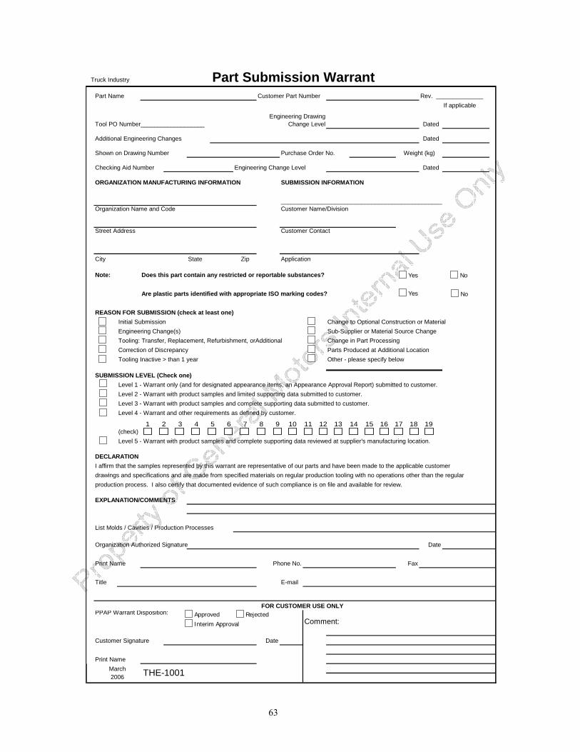
63
Truck Industry Part Submission WarrantPart Name Customer Part Number Rev. ______________
If applicable
Dated
Additional Engineering Changes Dated
Shown on Drawing Number Purchase Order No. Weight (kg)
Checking Aid Number Engineering Change Level Dated
ORGANIZATION MANUFACTURING INFORMATION SUBMISSION INFORMATION
________________________________________________Organization Name and Code Customer Name/Division
Street Address Customer Contact
City State Zip Application
Note: Does this part contain any restricted or reportable substances?
Are plastic parts identified with appropriate ISO marking codes?
REASON FOR SUBMISSION (check at least one)Initial Submission Change to Optional Construction or MaterialEngineering Change(s) Sub-Supplier or Material Source ChangeTooling: Transfer, Replacement, Refurbishment, orAdditional Change in Part ProcessingCorrection of Discrepancy Parts Produced at Additional LocationTooling Inactive > than 1 year Other - please specify below
SUBMISSION LEVEL (Check one)Level 1 - Warrant only (and for designated appearance items, an Appearance Approval Report) submitted to customer.Level 2 - Warrant with product samples and limited supporting data submitted to customer.Level 3 - Warrant with product samples and complete supporting data submitted to customer.Level 4 - Warrant and other requirements as defined by customer.
(check)Level 5 - Warrant with product samples and complete supporting data reviewed at supplier's manufacturing location.
DECLARATIONI affirm that the samples represented by this warrant are representative of our parts and have been made to the applicable customerdrawings and specifications and are made from specified materials on regular production tooling with no operations other than the regularproduction process. I also certify that documented evidence of such compliance is on file and available for review.
EXPLANATION/COMMENTS
List Molds / Cavities / Production Processes
Organization Authorized Signature Date
Print Name Phone No. Fax
Title E-mail
PPAP Warrant Disposition:Comment:
Customer Signature Date
Print Name
Engineering Drawing Change LevelTool PO Number___________________
FOR CUSTOMER USE ONLY
March THE-10012006
Yes No
Yes No
Approved Rejected
Interim Approval
1 2 3 4 5 6 7 8 9 10 11 12 13 14 15 16 17 18 19
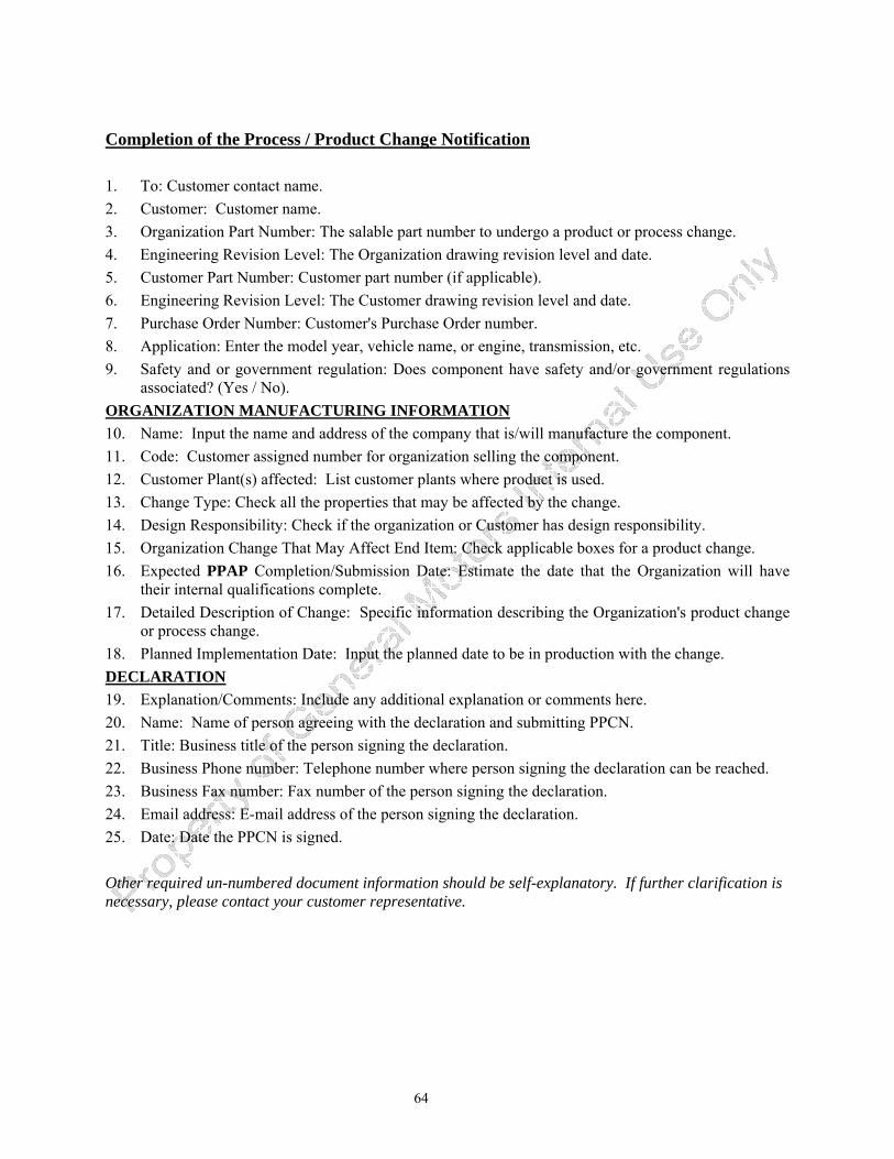
64
Completion of the Process / Product Change Notification 1. To: Customer contact name. 2. Customer: Customer name. 3. Organization Part Number: The salable part number to undergo a product or process change. 4. Engineering Revision Level: The Organization drawing revision level and date. 5. Customer Part Number: Customer part number (if applicable). 6. Engineering Revision Level: The Customer drawing revision level and date. 7. Purchase Order Number: Customer's Purchase Order number. 8. Application: Enter the model year, vehicle name, or engine, transmission, etc. 9. Safety and or government regulation: Does component have safety and/or government regulations
associated? (Yes / No). ORGANIZATION MANUFACTURING INFORMATION10. Name: Input the name and address of the company that is/will manufacture the component. 11. Code: Customer assigned number for organization selling the component. 12. Customer Plant(s) affected: List customer plants where product is used. 13. Change Type: Check all the properties that may be affected by the change. 14. Design Responsibility: Check if the organization or Customer has design responsibility. 15. Organization Change That May Affect End Item: Check applicable boxes for a product change. 16. Expected PPAP Completion/Submission Date: Estimate the date that the Organization will have
their internal qualifications complete. 17. Detailed Description of Change: Specific information describing the Organization's product change
or process change. 18. Planned Implementation Date: Input the planned date to be in production with the change. DECLARATION19. Explanation/Comments: Include any additional explanation or comments here. 20. Name: Name of person agreeing with the declaration and submitting PPCN. 21. Title: Business title of the person signing the declaration. 22. Business Phone number: Telephone number where person signing the declaration can be reached. 23. Business Fax number: Fax number of the person signing the declaration. 24. Email address: E-mail address of the person signing the declaration. 25. Date: Date the PPCN is signed. Other required un-numbered document information should be self-explanatory. If further clarification is necessary, please contact your customer representative.

65
Dimensional __________________________________ Materials
FunctionalDesign Responsibility: Customer Organization Appearance
Organization Change That May Affect End Item:
Product Change Engineering Drawing Change New or Revised Subcomponent
Expected PPAP Completion/Submission Date:
DETAILED DESCRIPTION OF PRODUCT/PROCESS CHANGE:
Planned Date of Implementation:
DECLARATION
:I hereby certify that representative samples will be manufactured using the revised product and/or process and verified,
Explanation/Comments:
NOTE: Please submit this notification at least 6 weeks prior to the planned change implementation!
March2006 THE-1002
Dated:
PRODUCT / PROCESS CHANGE NOTIFICATION
Complete this form and email to your customer organization whenever customer notification is required by the PPAPManual in Table 3.1. Your customer will respond back with an acknowledgement and may request additional changeclarification or PPAP submission requirements.
Purchase Order Number: Safety and/or government regulation:
To: Customer:
Organization Part Number:
Customer Part Number:
Engineering Revision Level: Dated:
Engineering Revision Level:
Street Address:Change Type (check all that apply)City, State & Zip:
Application:
ORGANIZATION MANUFACTURING INFORMATION
Name: Code:
Customer Plants Affected:
NAME: TITLE:
performance and durability. I also certify that documented evidence of such compliance is on file and available forcustomer review.
where appropriate, for dimensional change, appearance change, physical property change, functionally for
Contact your customer to determine if this form is available in an electronic format or if this form should be faxed.
FAX NO:BUSINESS PHONE NO:
E-MAIL: DATE:
1 2
3 4
5 6
7 9
8
10 11
13
12
14
15
16
17
18
19
20 21
22 23
24 25
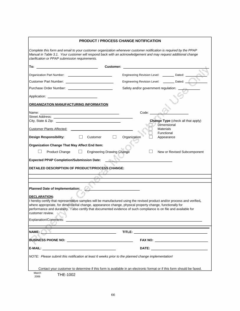
66
Dimensional __________________________________ Materials
FunctionalDesign Responsibility: Customer Organization Appearance
Organization Change That May Affect End Item:
Product Change Engineering Drawing Change New or Revised Subcomponent
Expected PPAP Completion/Submission Date:
DETAILED DESCRIPTION OF PRODUCT/PROCESS CHANGE:
Planned Date of Implementation:
DECLARATION
:I hereby certify that representative samples will be manufactured using the revised product and/or process and verified,
Explanation/Comments:
NOTE: Please submit this notification at least 6 weeks prior to the planned change implementation!
March2006
Contact your customer to determine if this form is available in an electronic format or if this form should be faxed.
FAX NO:BUSINESS PHONE NO:
E-MAIL: DATE:
Customer Plants Affected:
NAME: TITLE:
performance and durability. I also certify that documented evidence of such compliance is on file and available forcustomer review.
where appropriate, for dimensional change, appearance change, physical property change, functionally for
Street Address:Change Type (check all that apply)City, State & Zip:
Application:
ORGANIZATION MANUFACTURING INFORMATION
Name: Code:
Customer:
Organization Part Number:
Customer Part Number:
Engineering Revision Level: Dated:
Engineering Revision Level:
THE-1002
Dated:
PRODUCT / PROCESS CHANGE NOTIFICATION
Complete this form and email to your customer organization whenever customer notification is required by the PPAPManual in Table 3.1. Your customer will respond back with an acknowledgement and may request additional changeclarification or PPAP submission requirements.
Purchase Order Number: Safety and/or government regulation:
To:

67
68
GLOSSARY ACCREDITED LABORATORY is one that has been reviewed and approved by a nationally-recognized accreditation body or, as an alternative, a customer recognized accreditation body, conforming to ISO/IEC Guide 58 for calibration or test laboratory accreditation to ISO/IEC 17025, or national equivalent.
ACTIVE PART is one currently being supplied to the customer for original equipment or service applications. The part remains active until tooling scrap authorization is given by the appropriate customer activity. For parts with no customer-owned tooling or situations where multiple parts are made from the same tool, written confirmation from the customer Purchasing activity is required to deactivate a part.
NOTE: For bulk material, “active part” refers to the bulk material contracted, not the parts that are subsequently produced from that material.
APPEARANCE ITEM is a product that is visible once the vehicle is completed. Certain customers will identify appearance items on the engineering drawings. In these cases, special approval for appearance (color, grain, texture, etc.) is required prior to production part submission.
APPROVED is used in PPAP to mean that the parts, materials, and/or related documentation (or records submitted to, or reviewed by, the customer) meet all customer requirements. After approval or interim approval, the organization is authorized to ship product as directed by the customer.
APPROVED DRAWING is an engineering drawing signed by the engineer and released through the customer’s system.
APPROVED MATERIALS are materials governed either by industry standard specifications (e.g., SAE, ASTM, DIN, ISO) or by customer specifications.
APPROVED SOURCE LIST is a list of the organizations and suppliers that have been found to be acceptable to the customer. Utilizing product from an approved supplier does not relieve the organization of responsibility for the quality of that product.
ATTRIBUTE DATA are qualitative data that can be counted for recording and analysis. Examples include the presence or absence of a required label, the installation of all required fasteners.
AUTHORIZED CUSTOMER REPRESENTATIVE(S) is the individual or individuals having approval authority on behalf of the customer.
NOTE: The customer’s process should identify the approval authority.
BLACK BOX refers to a part (e.g., an assembly, electrical device, mechanical device, or control module) where design responsibility belongs to the organization or the supplier. Black Box requirements are generally limited to those characteristics/items required for customer interface connections and verification of functional requirements. “O.D.D.” (Outside Design and Development) has the equivalent meaning.
BULK MATERIAL is a substance (e.g., non-dimensional solid, liquid, gas) such as adhesives, sealants, chemicals, coatings, fabrics, lubricants, etc. A bulk material may become production material if issued a customer production part number (see PRODUCTION MATERIAL).
BULK MATERIALS REQUIREMENTS CHECKLIST defines the customer PPAP requirements for bulk material. (see Appendix F).
CAD/CAM MATH DATA is a form of design record by which all dimensional information necessary to define a product is conveyed electronically. When this design record is used, the organization is responsible for obtaining a drawing to convey results of dimensional inspection.
69
CALIBRATION is a set of operations which compares values taken from a piece of inspection, measuring and test equipment or a gage to a known standard under specified conditions.
CAPABILITY is the total range of inherent variation in a stable process. (see the Statistical Process Control reference manual)
CHECKED PRINT is a released engineering drawing with actual measurement results recorded by the organization adjacent to each drawing dimension and other requirements.
CONFORMANCE means that the part or material meets the customer’s specifications and requirements.
CONTROL - see STATISTICAL CONTROL.
CONTROL CHARTS – see the Statistical Process Control reference manual.
CONTROL PLANS are written descriptions of the system for controlling production parts or bulk materials and processes. They are written by organizations to address the important characteristics and engineering requirements of the product. Each part must have a Control Plan, but in many cases, “family” Control Plans can apply to a number of parts produced using a common process. Refer to Advanced Product Quality Planning and Control Plan reference manual, ISO/TS 16949, and customer-specific requirements.
CUSTOMER is the recipient of the organization's or supplier’s product or service.
DESIGN-INTENDED ROBUST RANGE are limits within which parameters may be allowed to vary while still ensuring that a product complies with fitness for use requirements.
DESIGN RECORD is the part drawing, specifications, and/or electronic (CAD) data used to convey information necessary to produce a product.
FAILURE MODE AND EFFECTS ANALYSIS (FMEA) is a systematic group of activities intended to: (a) recognize and evaluate the potential failure of a product/process and the effects of that failure, (b) identify actions that could eliminate or reduce the chance of the potential failure occurring, and (c) document the entire process. It is complementary to the process of defining what a design or process must do to satisfy the customer. Refer to Potential Failure Modes and Effects Analysis reference manual.
INITIAL PROCESS STUDY – see the Statistical Process Control reference manual.
LABORATORY is a test facility that may include chemical, metallurgical, dimensional, physical, electrical, reliability testing or test validation.
LABORATORY SCOPE is quality record containing the following:
• the specific tests, evaluations and calibrations an organization’s laboratory has the ability and competency to perform
• a list of the equipment which it uses to perform the above • a list of the methods and standards to which it performs the above.
MARKED PRINT is an engineering drawing modified, signed, and dated by the customer engineer (the engineering change number must be included).
ORGANIZATIONS are providers of: a) production materials, b) production or service parts, c) assemblies, or d) heat treating, welding, painting, plating or other finishing services, directly to the OEM or other customers requiring this document.
PART SUBMISSION WARRANT (PSW) is an industry-standard document required for all newly-tooled or revised products in which the organization confirms that inspections and tests on production parts show conformance to customer requirements.
70
PERISHABLE TOOLS are drill bits, cutters, inserts, etc. used to produce a product and which are consumed in the process.
PROCESS is a set of interrelated or interacting activities which transforms inputs into outputs.
PROCESS FLOW DIAGRAM is a schematic representation of the process flow.
NOTE 1: For PPAP, the process flow diagram should focus upon the manufacturing process, including rework and repair.
NOTE 2: Process flow diagrams can apply to any aspect of the business.
PRODUCTION ENVIRONMENT is the manufacturing location within the production site which includes the production tooling, gaging, process, materials, operators, environment, and process settings, e.g., feeds, speeds, cycle times, pressures, temperatures, quoted line rate. Environment is defined as all of the process conditions surrounding or affecting the manufacture and quality of a part or product. Environment will vary for each site, but generally includes: housekeeping, lighting, noise, HVAC, ESD controls, and safety hazards relating to housekeeping.
PRODUCTION MATERIAL is material which has been issued a production part number by the customer and is shipped directly to the customer.
PRODUCTION PART is manufactured at the production site using the production tooling, gaging, process, materials, operators, environment, and process settings, e.g., feeds/speeds/cycle times/pressures/temperatures.
PRODUCTION PART APPROVAL SUBMISSION is based on specified quantities of production parts or production materials taken from the significant production run made with production tooling, processes, and cycle times. These parts or materials submitted for production part approval are to be verified by the organization as meeting all specified requirements from the design record.
PRODUCTION RATE is the agreed upon number of parts produced in a planned time period to meet customer assembly or manufacturing plant production volume requirements - with consideration of other product mix and machine availability.
NOTE: The agreed production rate is typically specified in the purchase agreement.
QUALITY INDICES are measures of capability or performance for either product or process, such as Cpk or Ppk. See the Statistical Process Control reference manual.
QUALITY PLANNING is a structured process for defining the methods (e.g., measurements, tests) that will be used in the production of a specific product or family of products (e.g., parts, materials). Quality planning embodies the concepts of defect prevention and continual improvement as contrasted with defect detection (see Advanced Product Quality Planning and Control Plan reference manual).
QUALITY RECORD is a document stating results achieved or providing evidence of activities performed, e.g., test results, internal audit results, calibration data.
REGULAR PRODUCTION TOOLING is the tooling with which the manufacturer intends to produce production product.
SALEABLE PRODUCT/PART - refers to the product/part specified on the contract between the customer and organization.
SIGNIFICANT PRODUCTION RUN - see PPAP, 2.1.
SITE is a location at which value-added manufacturing processes occur.
71
SPECIAL CHARACTERISTICS are product characteristics or manufacturing process parameters which can affect safety or compliance with regulations, fit, function, performance or subsequent processing of product. Refer to customer-specific requirements.
SPECIFICATION is a document stating requirements.
NOTE: For PPAP, every feature of the product as identified by engineering specifications must meet requirements. Actual measurement and test results are required. Specifications should not be confused with control limits which represent “the voice of the process.”
STABLE PROCESSES are processes that are in statistical control. See the Statistical Process Control reference manual.
STATISTICAL CONTROL is the condition of a process from which all special causes of variation have been eliminated and only common causes remain. See the Statistical Process Control reference manual.
SUBMISSION LEVEL refers to the level of evidence required for PPAP submission (see PPAP, 4.1).
SUPPLIERS are providers of production materials, or production or service parts, assemblies, heat treating, welding, painting, plating or other finishing services directly to an organization supplying the OEM or other customers requiring this document.
TOOL is defined as the portion of process machinery which is specific to a component or sub-assembly. Tools (or tooling) are used in process machinery to transform raw material into a finished part or assembly.
VALIDATION is confirmation, through the provision of objective evidence, that the requirements for a specific intended use or application have been fulfilled.
VARIABLES DATA are quantitative data, where measurements are used for analysis. Examples include the diameter of a bearing journal in millimeters, the closing effort of a door in Newtons, the concentration of electrolyte in percent, or the torque of a fastener in Newton-meters.
VERIFICATION is confirmation, through the provision of objective evidence, that specified requirements have been fulfilled
WARRANT - See Part Submission Warrant.