Embed Size (px)
DESCRIPTION
divisions
Citation preview

DIVISION 2: SITE CONSTRUCTION
PIPINGS – STORM DRAIN
by:
HP Storm
An addition to our proven line of pipe products, HP Storm
is a high-performance polypropylene pipe for gravity-flow storm
drainage applications. HP Storm is the perfect choice when
premium joint performance and/or greater pipe stiffness is required.
HP Storm couples advanced polypropylene resin technology with a
proven, dual-wall profile design for superior performance and
durability. The smooth interior wall offers additional strength as well as superior flow.
This innovative product meets or exceeds typical standards for pipe stiffness and joint integrity and
meets ASTM F2736, ASTM F2881 and AASHTO M330 for the respective diameters.
Minimum Cover in Traffic Applications
Pipe diameters from 12- through 48-inch (300-1200 mm) installed in traffic areas (AASHTO H-25 or HS-
25 loads) must have at least one foot (0.3m) of cover over the pipe crown, while 60-inch (1500 mm) pipes
must have at least 24 inches (0.6m) of cover. The backfill envelope must be constructed in accordance with
the Installation section (Section 5) of the Drainage Handbook and the requirements of ASTM D2321. The
backfill envelope must be of the type and compaction listed in Appendix A-5, Table A-5-2 of the Drainage
Handbook. In Table 1 below, this condition is represented by a Class III material compacted to 90%
standard Proctor density, although other material can provide similar strength at slightly lower levels of
compaction. Structural backfill material should extend to the crown of the pipe; the remaining cover should
be appropriate for the installation and as specified by the design engineer. If settlement or rutting is a
concern, it may be appropriate to extend the structural backfill to grade. Where pavement is involved, sub-
base material can be considered in the minimum burial depth. While rigid pavements can be included in
the minimum cover, the thickness of flexible pavements should not be included in the minimum cover.
Additional information that may affect the cover requirements is included in the Installation section (Section
5) of the Drainage Handbook. Some examples of what may need to be considered are temporary heavy
equipment, construction loading , paving equipment and similar loads that are less than the design load, the
potential of pipe flotation, and the type of surface treatment which will be installed over the pipe zone.
Maximum Cover
Wall thrust generally governs the maximum cover a pipe can withstand and conservative maximum cover
heights will result when using the information presented in the Structures section (Section 2) of the

Drainage Handbook. Table 2 below shows the material properties consistent with the expected
performance characteristics for HP Storm materials for a 50-year design life.
The maximum burial depth is highly influenced by the type of backfill and level of compaction around the
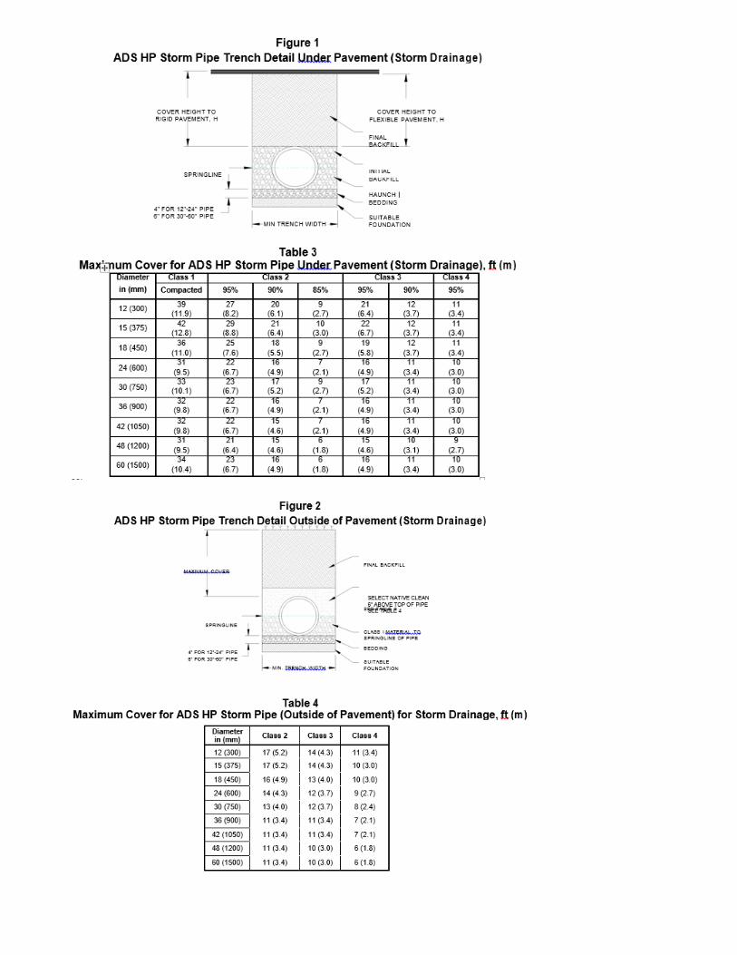
pipe. General maximum cover limits for ADS HP Storm use in storm drainage applications are shown in
Tables 3 and 4 for a variety of backfill conditions. Please note Table 3 is based on the installation of HP
Storm under pavement using a uniform backfill type and compaction level, as depicted in Figure 1; fill
heights in Table 4 are based on the installation of HP Storm outside of pavement using differing backfill
materials in the backfill zone, as depicted in Figure 2.
Table 3 was developed assuming pipe is installed in accordance with ASTM D2321 and the Installation
section (Section 5) of the Drainage Handbook. Additionally, the calculations assume a hydrostatic load
around the pipe and extending 12 inches above the crown of the pipe, incorporate the maximum safety
factors represented in structures section of the Drainage Handbook, use material properties consistent with
the expected performance characteristics for HP Storm materials as shown in Table 4 below, and assume
the native (in-situ) soil is of adequate strength and is suitable for installation. For applications requiring fill
heights greater than those shown in Table 4, contact an ADS Engineer.
It should be noted that while an installation condition as depicted in Figure 3 can be modeled in
structural evaluations, there are constructability and practical installation considerations that should
be taken into account when a designer is determining the best backfill plan for a project.
1. Changing material types at the springline of the pipe requires accounting for the different soil
confining strengths of the two materials. This variation in soil strengths can result in a reduced
cover height when compared to an installation where a single material type is used for the
entire pipe embedment. This reduction can be seen in Tables 3 and 4 below. Where materials
of differing strengths are used in the pipe embedment, susceptibility to pipe deflection can
increase if the materials are not properly placed and compacted.
2. The fill heights shown in Table 4 are based upon a minimum compaction density of 85% being
achieved for the native material above the pipe springline. When considering moisture content
and compaction effort, adequate compaction of Class 3 and 4 materials can be more difficult
to achieve compared to the effort of a Class 1 material used in the haunch zone of the pipe.
3. When materials of different gradation are placed adjacent to each other, filter fabric separation or properly graded material, under the guidance of a geotechnical engineer, is recommended in order to prevent the migration of fines into the open-graded material.
These considerations are not intended to explicitly allow or discourage the use of native
materials above the pipe springline, but simply to state that such embedment can be successful
when implemented correctly. While ADS supports that the product can perform well within
these installation parameters, overall successful execution is dependent not only on the product,
but on coordination, input and agreement between the owner, engineer and contractor, based on
each party’s needs.
DIVISION 3: CONCRETE
WALL PANELS
Acrovyn Wall Panels: CHAMELEON
SIMULATED METAL WALL PANELS
For the look of real metal with the superior
performance qualities of Acrovyn.
Available with beveled or square edges.
Installation
Starting Procedure
If The Installation Is Full Height, Establish A Plumb Line At The Edge Of The First Panel. This
Will Serve As A Starting Point For Material To Be Installed On That Wall And Ensure That All
Remaining Panels Will Be Plumb. A Plumb Line Should Be Established At The Beginning Of
Each New Run Of Material.
If The Wall Panel Is To Be Installed At Wainscot Height, Determine What The Finished Height
Is To Be And Establish A Level Line The Entire Length Of The Run. Install All Wall Paneling
By Aligning The Top Edge With This Line. Establish A Level Line At The Beginning Of Each
New Run Of Material.
If Ledge Trim Is Required It Should Be Installed Prior To Panel Installation. Ledge Trims
Should Be Fastened By Small Drywall Screws (By Others) And Securely Fastened To Studding
16" [406.4mm] O.C.
Determining Where The First Plumb Line Is Located Will Be The Responsibility Of The
Installer. Project Drawings, If Available, Should Be Reviewed In Case Joint Locations Have
Already Been Predetermined.
It Is Suggested That The Center Of The Wall Be The Starting Point For Panel Installation.
Panels Can Be Installed From The Center; Working Outward Providing For End Panels That
Are Of An Equal Dimension.
At The End Of A Run, Cut End Panel(S) To Size And Make Necessary Cutouts. Dry Fit The
Panels Prior To Applying The Adhesive. Place The Panel Face Down On A Worktable, While
Protecting The Finished Surface, And Wipe The Back With A Clean Damp Cloth To Remove
Any Dust And Dirt.
Apply A 1/4" Bead Of Construction Adhesive To The Panel. Apply The Adhesive On 18"
[457.2mm] To 20" [508mm] Centers And Around The Entire Perimeter Maintaining Maximum
1” [25.4mm] Space From The Edge. One 28-Oz Tube Will Cover 80 Ft2 [7.4m2] Of Panels The
Bead Size Should Be Increased On Uneven Substrates To Insure Adhesion.
Panel Installation

Align The Panel With The Level Or Plumb Line Established Earlier. Once Positioned Install
The Panel To Substrate By Pushing It Against The Wall With Even Pressure, Ensuring Full
Adhesive Transfer.
Immediately Remove Any Adhesive From The Panel That May Have Accidentally Gotten On
The Acrovyn Using Isopropyl Alcohol, Mineral Spirits Or Diluted Acetone. Trim Screws Or
Finishing Nails Must Be Used To Secure The Panel In Place Until The Adhesive Cures.
Placements Of Trim Screws Or Finishing Nails Must Be Concealed With Cove Base, Wainscot
Molding Or Filled With Color Match Caulk.
Trim Installation
If Ledge Trim Is Required Please Refer To The Section Entitled Installation Starting Procedure.
For Multi-Panel Runs, Install Applicable Vertical Joint, Edge Trim And Inside And Outside
Corner Pieces. If Color Matched Caulk Is Used At Vertical Joints, Allow A Minimum 1/16"
Space Between Panels. Notch The Back Of Wainscot Moldings Where It Intersects Vertical Or
Edge Trim. Apply A Small Bead Of Silicone Adhesive To The Inside Of The Wainscot Trim
And Snap Over The Top Of The Previously Installed Panels.
DIVISION 4: MASONRY
LIME MASONRY
MORTASEAL Mason's Lime
Description
MORTASEAL® Mason’s Lime is a fine-grind, white, high-purity dolomitic lime, fully
hydrated for immediate use. When properly combined with Portland cement and sand, it creates
a lime mortar having superior performance and ageless durability.
MORTASEAL® Mason’s Lime complies with ASTM C207, Type S. This product is available
in durable 3- ply, weather-resistant and poly-lined 50-lb. bags.
Uses
Recommended for all Type M, S, N and 0 cement- lime mortar (ASTM C270) applications in
interior and exterior masonry walls.
Advantages
High Plasticity
MORTASEAL® Mason's Lime develops exceptional plasticity and workability immediately
upon mixing with water by machine or hand. Carries more sand than most masonry cements or
mortar cements for better yield without sacrificing workability.
Excellent Water Retentivity
Increases workability and bonding characteristics, reduces segregation of materials, requires less
retempering of mortar during use. MORTASEAL® Mason’s Lime mortar resists suction, even
from dry masonry, leaves ample time to strike joints.
Balanced Strength
Permits optimum balance between workability and bond strength; provides adequate
compressive and tensile strength to accommodate structural move- ment, plus flexibility to
absorb normal stresses from winds and vibration.
Weather Resistance
Offers tight, uniform bond to resist water penetration, helps prevent efflorescence, leaky walls
and frost damage. Self-healing properties of MORTASEAL® Mason’s Lime repair fine cracks
for many years after construction.
Lower Costs
Easily mixed, makes a richer mortar that carries more sand, works easier, and can save on
cementitious material cost. Masonry units lay up faster with less waste and “shake-up” time for
greater on-site production.
Materials
a. Portland Cement—Conforming to ASTM C15O, Type I.

b. Hydrated Lime—MORTASEAL® Mason’s Lime, conforming to ASTM C207, Type S. c.
Aggregate—Sand conforming to ASTM C144.
d. Water-Clean and free of deleterious amounts of acids, alkalies and organic materials.
Mixes
a. Type M Mortar, shall be mixed in proportion of one bag Portland Cement, one-quarter bag
MORTASEAL® Mason’s Lime, to not more than 3 3/4 cu. ft. sand (1: 1/4 : 3 3/4). b. Type S
Mortar shall be mixed in proportion of one bag Portland Cement, one-half bag MORTASEAL®
Mason’s Lime, to not more than 4 1/2 cu. ft. sand (1: 1/2 : 4 1/2). c. Type N Mortar shall be
mixed in proportion of one bag Portland Cement, one bag MORTASEAL® Mason’s Lime, to
not more than 6 cu. ft. sand (1: 1: 6). d. Type 0 Mortar shall be mixed in proportion of one bag
Portland Cement, 2 bags MORTASEAL® Mason’s Lime, to not more than 9 cu. ft. sand (1: 2 :
9)
Execution
Proportion ingredients accurately and mix for at least 5 minutes in mechanical batch mixer with
enough water to produce a workable consistency.
Mortar Application
Lay mortar in a uniform bed and completely fill joints between masonry units.
DIVISION 5: METAL
METAL DECKING
ROOF DECK - 1.0RD, 1.0RDV Deck
Type 1.0RD provides an economical option when support spacing is small. Where rigid roofing
insulation is used with 1.0RD deck, a minimum 1” thickness is required.
Available with nested side laps only.
Available as a vented deck, type 1.0RDV is manufactured with slot vents in the bottom flutes. The
openings equal 0.5% of total surface. Type 1.0RDV is to be specified when venting is required for
cementitious insulation fill.
1.0RD deck can also be used as wall siding.
DIVISION 6: WOOD & PLASTIC
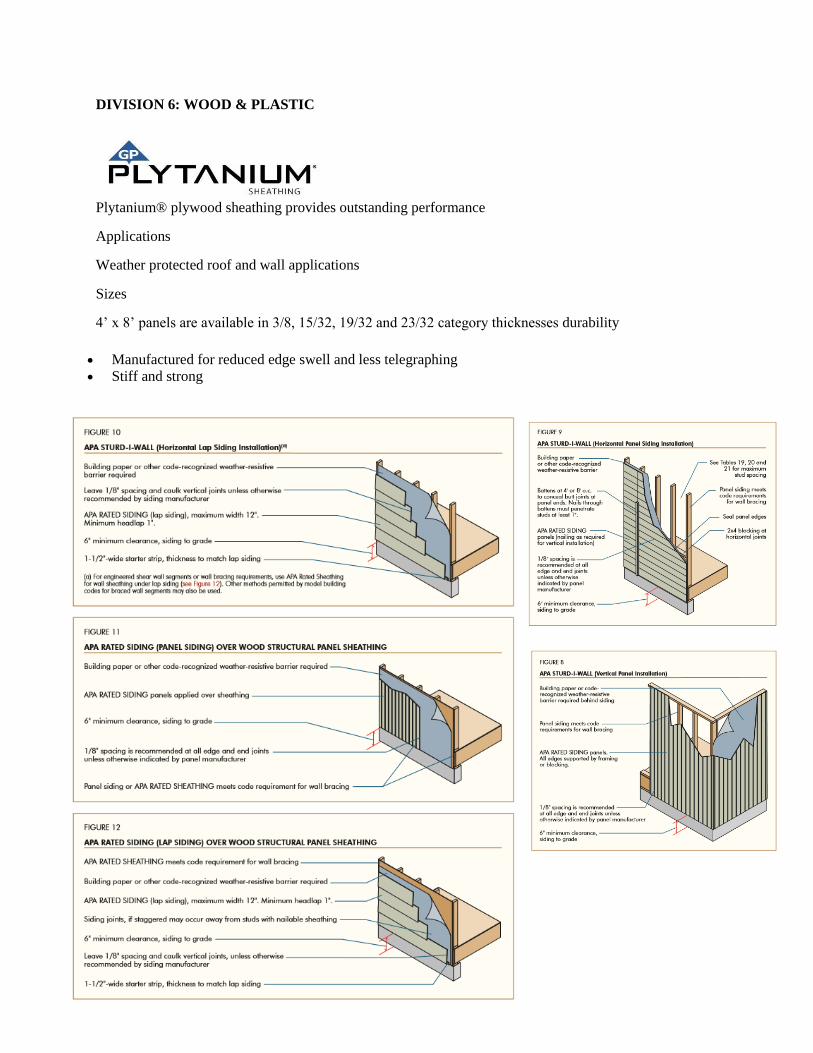
Plytanium® plywood sheathing provides outstanding performance
Applications
Weather protected roof and wall applications
Sizes
4’ x 8’ panels are available in 3/8, 15/32, 19/32 and 23/32 category thicknesses durability
Manufactured for reduced edge swell and less telegraphing
Stiff and strong

DIVISION 7: THERMAL & NOISTURE PROTECTION
ASPHALT SHINGLES
Asphalt roofing shingles are the most common roofing material used by homeowners in North America
today. At IKO Industries Ltd. we have been manufacturing asphalt roofing shingles since the 1950’s and
our 3,000 employees worldwide deliver various roofing and waterproofing materials for residential homes
as well as commercial buildings.
DIVISION 8: DOORS & WINDOWS
WOODEN DOOR
2014 OPPEIN Classic White Simple Wooden Door
Home Furniture-wooden Door-Interior Door
Model NO.: MSJD43
Surface Finishing: White matte lacquer
Special Function: Security
Product Material: MDF or Plywood
Position: Available in living room or
entrance room or bedroom etc.
Open Style: Swing
Wooden Door Feature:
This door is classic style, unique corner
flowers, full of art, suit to match fashion
furnish including new chinese style, simple
euro style etc

DIVISION 9: FINISHES
GOLD BOND GAUGING PLASTER
Description
Gold Bond® BRAND Gauging Plaster, quick set or slow set type, is designed for use with finish lime. It
is specially ground, calcined gypsum, which readily mixes with water and lime putty. Proper
proportioning is essential, since gauging adds strength and hardness to the finish surface by reinforcing
the plastic non-setting lime against shrinkage and cracking. A finish coat of gypsum gauging plaster and
finish lime, job mixed 2 parts hydrated lime to 1 part plaster by weight, is designed primarily for interior
smooth trowel application over a gypsum plaster basecoat. Smooth finish plasters should be applied at a
thickness of not more than 1/16". Texture finishes should be applied at a thickness of not more than 1/8".
Complies with ASTM Designation C 28.
Applications
Gauging Plaster is designed for use with finish lime. It is specially ground, calcined gypsum, which
readily mixes with water and lime putty. A finish coat of gypsum gauging plaster and finish lime is
designed primarily for interior smooth trowel application over a gypsum plaster basecoat.
Bag Weight
Quick Set - 50 lbs. (22.5 kg)
Slow Set - 50 lbs. (22.5 kg)
DIVISION 10: SPECIALTIES
FIRE EXTINGGUISHERS
HAND HELD EXTINGUISHERS
Our goal is to provide our customers with quality fire extinguishers at a great value. In pursuit of this, we
manufacture all our products in the U.S.A. We mill and blend our own dry chemical agents, machine the
component parts, assemble and then test our units to the highest quality standards.
FEATURES
- Manufactured to meet UL’s rigorous standards for commercial hazard protection and backed by our
manufacturer’s warranty.
- Rechargeable.
- Anodized metal & brass valve assemblies for superior strength and corrosion resistance.
- Industrial grade steel & aluminum cylinders with polyester powder coating designed to withstand harsh
environments & rough usage.
- Metal pull pins, vehicle brackets and wall hooks for extended unit service life
- Color-coded gauges show operating status at-a-glance..
- Extinguishers have model and serial number bar coding for easy and accurate maintenance history.
DIVISION 11: EQUIPMENTS
REFRIGIRATOR
GE Profile™ Series 23.3 Cu. Ft. Counter-Depth Side-by-Side Refrigerator
WEIGHTS & DIMENSIONS
Approximate Shipping Weight - 360 lb
Overall Height - 69 1/4 in
Height to Top of Case - 68 3/4 in
Overall Width - 35 3/4 in
Back Air Clearances - 2 in
Side Air Clearances - 0 1/8 in
POWER / RATINGS
Volts/Hertz/Amps - 120v;
60Hz; 15A

DIVISION 12: FURNISHINGS
BLINDS
SOMNER®
Features & Benefits
UV protection
SUNSCREEN FOR YOUR VALUABLES
Protect your furniture, flooring and artwork from fading with at least 75% protection from harmful UV
rays.
Absorb Sound
REDUCE OUTSIDE NOISE
Softex™ is a texturing process used on some of our Somner louvers that helps reduce noise levels. The
degree of sound control will depend on the fabric you choose, so if this is an important feature to you, be
sure to discuss it with your sales expert.

DIVISION 13: SPECIAL CONSTRUCTION
SPRINGKLER SYSTEM
Pre-action fire sprinkler systems employ the basic concept of a dry pipe system in that water is not
normally contained within the pipes. The difference, however, is that water is held from piping by an
electrically operated valve, known as a pre-action valve. Valve operation is controlled by independent
flame, heat, or smoke detection.
Two separate events must happen to initiate sprinkler discharge. First, the detection system must identify
a developing fire and then open the pre-action valve. This allows water to flow into system piping, which
effectively creates a wet pipe sprinkler system. Second, individual sprinkler heads must release to permit
water flow onto the fire.
In some instances, the pre-action system may be set up with a double interlock in which pressurized air or
nitrogen is added to system piping. The purpose of this feature is two-fold: first to monitor piping for
leaks and second to hold water from system piping in the event of inadvertent detector operation. The
most common application for this system type is in freezer warehouses.
DIVISION 14: CONVEYING SYSTEM
ELEVATORS
Machine-Roomless Elevators
This revolutionary elevator system is based on the first major breakthrough in
lifting technology in nearly 100 years. Designed for buildings between two
and 30 stories, this system employs a smaller sheave than conventional geared
and gearless elevators. The reduced sheave size, together with a redesigned
machine, allows the machine to be mounted within the hoistway itself—
eliminating the need for a bulky machine room on the roof.
Just as unique are the flat polyurethane-coated steel belts, an Otis invention
for the Gen2™ elevator system, that replace the heavy, woven steel cables
that have been the industry standard since the 1800s. The belts make the
smaller sheave possible. They are only 0.1 inch (3 mm) thick, yet they are as
strong as woven steel cables and far more durable, flexible and space-saving.
Machine-roomless elevators are ideal for a variety of applications—and the
most unusual, such as the Christ the Redeemer monument in Rio de Janeiro.

DIVISION 15: MECHANICAL
BOILERS
Heavy Commercial Steam
Helo Heavy Commercial Steam by Amerec
AI boilers are the steam generators of choice for large commercial steam rooms and
can help you create an inviting, relaxing environment that adds real value and
generates positive word of mouth and returns for your business. The AI Series is
specially designed for easy on-site maintenance and hands-off, automated operation.
From their corrosion-resistant exteriors to their multiple safety features, AI boilers
provide a welcome, genuine steam bath experience at less cost and with less hassle.
BUILT TO LAST
AI boilers feature all-steel construction with powder coat exterior, brass fittings, and
stainless steel feet to prevent corrosion. Designed to minimize downtime, AI boilers
are easy to access and service, with integrated diagnostic systems using LED indicator lights to alert you
to any problems.
IT1/IT2 CONTROLS
IT thermostats (1 for one room installations, 2 for two room installations) are boiler-mounted time and
temperature controls designed to be easy-to-understand and use. A separate thermostat is require for each
steam room.
ADI CoolFlush™
A drain and flush system that automatically performs recommended daily draining and flushing of the
boiler tank to reduce build-up of solids such as scale and sludge. Uses a computer controlled drain cycle
to add and drain water in steps, rinsing the tank and draining water at or below 140º F. Available with
optional Digital Run Clock.
Powerful dependable steam boiler for large commercial spaces
One or two room operation, each controlled individually by low voltage on/off switches for
maximum ease of use
Low service and maintenance requirements, saving time and other costs
ASME H-stamped Low-Pressure Vessel, National Board Registered
UL Listed
UPGRADE YOUR BOILER W/ T100 TOUCH SCREEN CONTROL
T100 TOUCH CONTROL FEATURES:
Touch screen operation for easy control of temperature and time settings
Large screen displays steam bath temperature and time of day
Displays temperature in Fahrenheit or Celsius
Sleep mode with integral sensor to activate screen when approached
Delayed start feature to pre-heat steam room at selected time up to 24 hours in advance
Multiple language settings include English and Spanish
Remote mounted sensor allows the Touch control to be mounted inside or outside the steam
shower or steam room
Flush-mount, low-profile installation
Installed dimensions 6-3/8"H x 4"W
DIVISION 16: ELECTRICAL
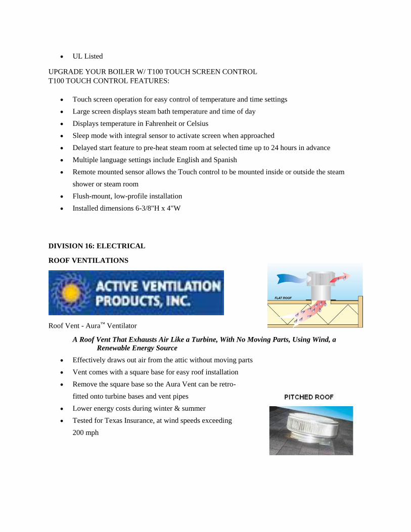
ROOF VENTILATIONS
Roof Vent - Aura™ Ventilator
A Roof Vent That Exhausts Air Like a Turbine, With No Moving Parts, Using Wind, a
Renewable Energy Source
Effectively draws out air from the attic without moving parts
Vent comes with a square base for easy roof installation
Remove the square base so the Aura Vent can be retro-
fitted onto turbine bases and vent pipes
Lower energy costs during winter & summer
Tested for Texas Insurance, at wind speeds exceeding
200 mph