Embed Size (px)
Citation preview
PowerPoint® PresentationPowerPoint® Presentation
Chapter 8Chapter 8InvertersInverters
AC Power • Inverters • Power Conditioning Units • Inverter Features and Specifications
AC Power • Inverters • Power Conditioning Units • Inverter Features and Specifications
Chapter 8 — InvertersChapter 8 — Inverters
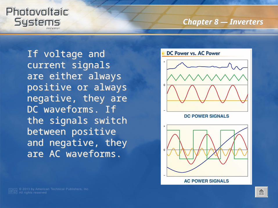
If voltage and current signals are either always positive or always negative, they are DC waveforms. If the signals switch between positive and negative, they are AC waveforms.
If voltage and current signals are either always positive or always negative, they are DC waveforms. If the signals switch between positive and negative, they are AC waveforms.
Chapter 8 — InvertersChapter 8 — Inverters
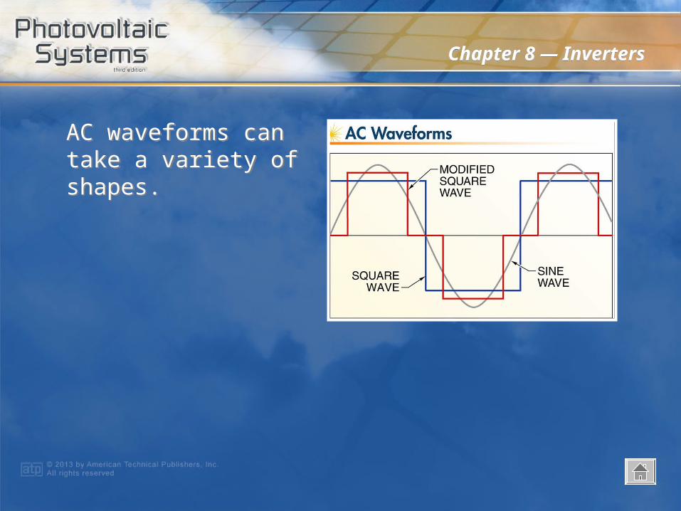
AC waveforms can take a variety of shapes.AC waveforms can take a variety of shapes.
Chapter 8 — InvertersChapter 8 — Inverters
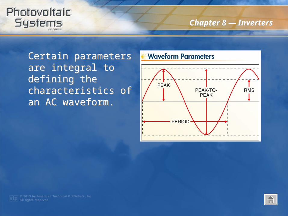
Certain parameters are integral to defining the characteristics of an AC waveform.
Certain parameters are integral to defining the characteristics of an AC waveform.
Chapter 8 — InvertersChapter 8 — Inverters
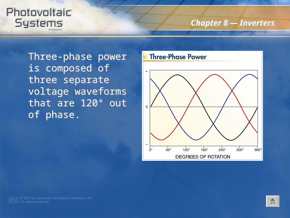
Three-phase power is composed of three separate voltage waveforms that are 120° out of phase.
Three-phase power is composed of three separate voltage waveforms that are 120° out of phase.
Chapter 8 — InvertersChapter 8 — Inverters
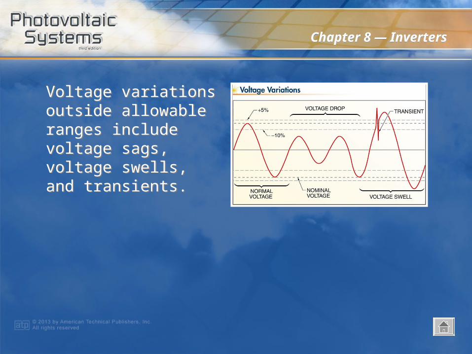
Voltage variations outside allowable ranges include voltage sags, voltage swells, and transients.
Voltage variations outside allowable ranges include voltage sags, voltage swells, and transients.
Chapter 8 — InvertersChapter 8 — Inverters
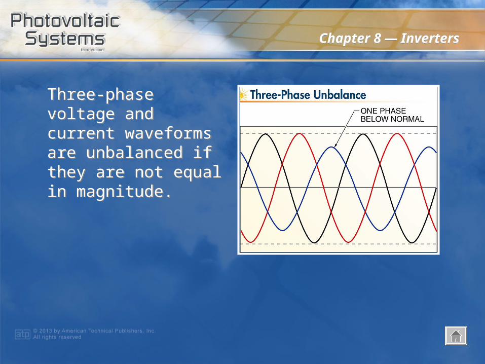
Three-phase voltage and current waveforms are unbalanced if they are not equal in magnitude.
Three-phase voltage and current waveforms are unbalanced if they are not equal in magnitude.
Chapter 8 — InvertersChapter 8 — Inverters
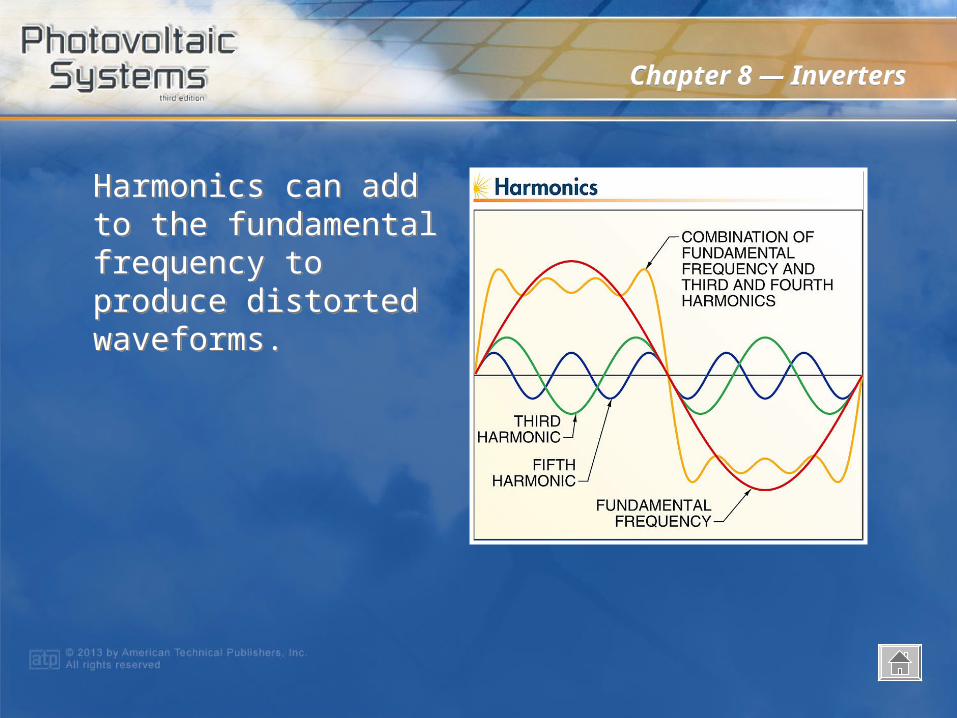
Harmonics can add to the fundamental frequency to produce distorted waveforms.
Harmonics can add to the fundamental frequency to produce distorted waveforms.
Chapter 8 — InvertersChapter 8 — Inverters
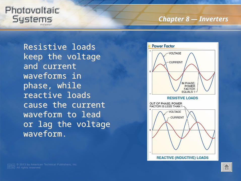
Resistive loads keep the voltage and current waveforms in phase, while reactive loads cause the current waveform to lead or lag the voltage waveform.
Resistive loads keep the voltage and current waveforms in phase, while reactive loads cause the current waveform to lead or lag the voltage waveform.
Chapter 8 — InvertersChapter 8 — Inverters
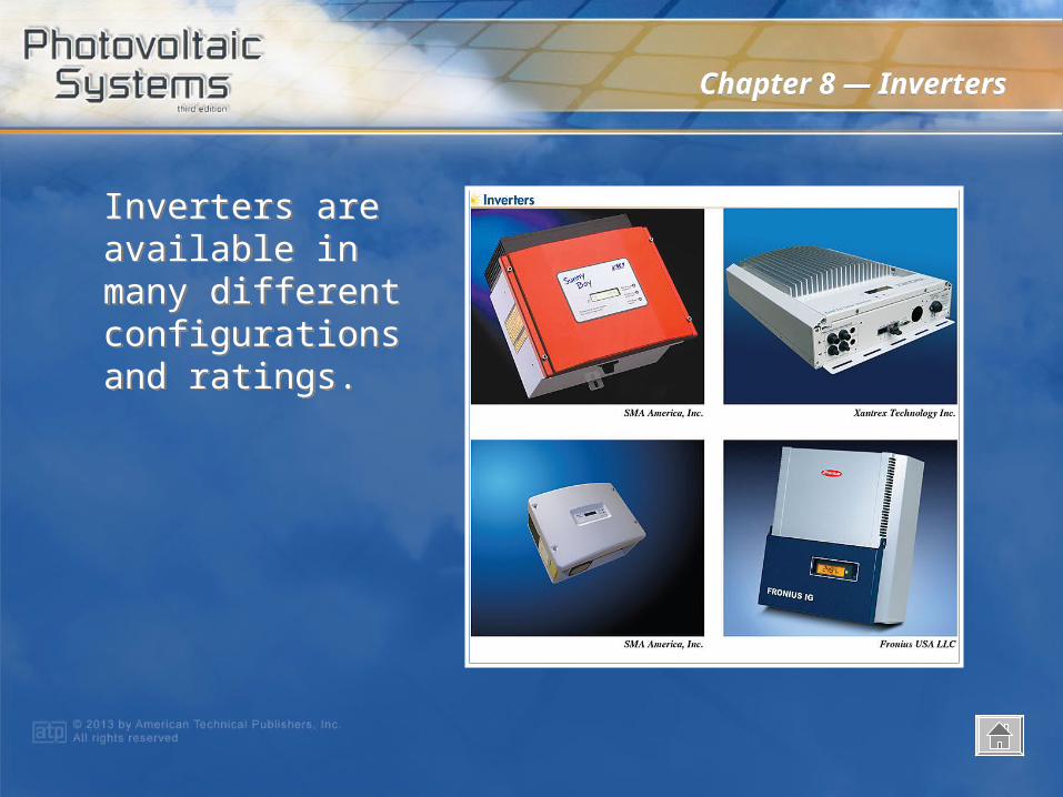
Inverters are available in many different configurations and ratings.
Inverters are available in many different configurations and ratings.
Chapter 8 — InvertersChapter 8 — Inverters
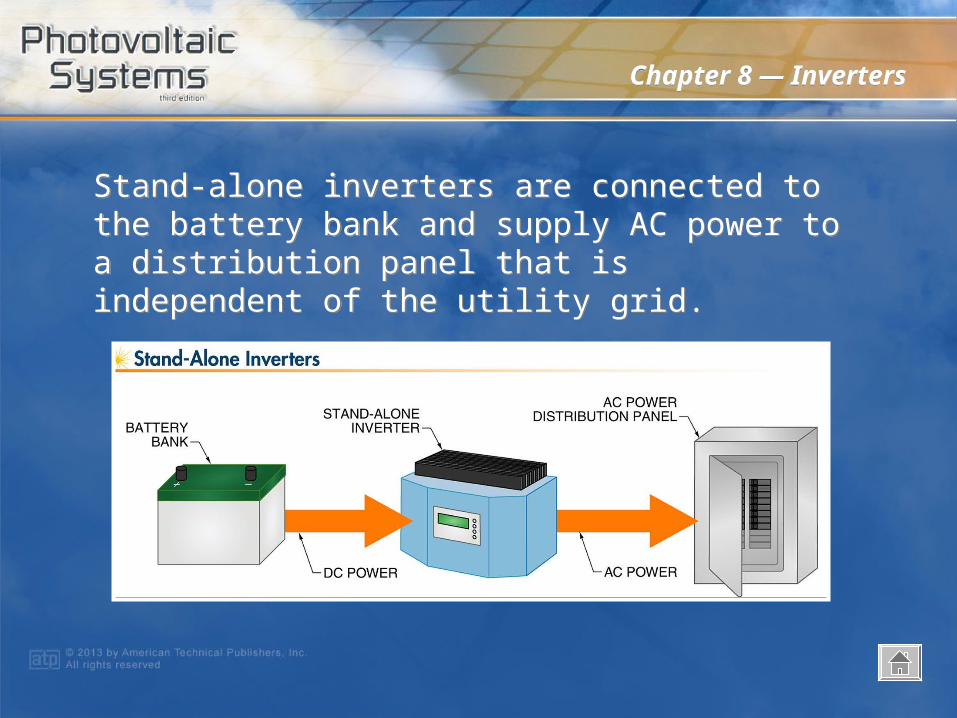
Stand-alone inverters are connected to the battery bank and supply AC power to a distribution panel that is independent of the utility grid.
Stand-alone inverters are connected to the battery bank and supply AC power to a distribution panel that is independent of the utility grid.
Chapter 8 — InvertersChapter 8 — Inverters
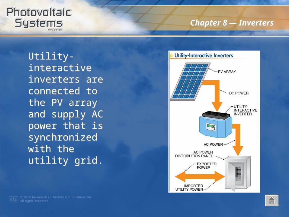
Utility-interactive inverters are connected to the PV array and supply AC power that is synchronized with the utility grid.
Utility-interactive inverters are connected to the PV array and supply AC power that is synchronized with the utility grid.

Chapter 8 — InvertersChapter 8 — Inverters
String inverters are commonly used in residential and small commercial PV systems.
String inverters are commonly used in residential and small commercial PV systems.
Chapter 8 — InvertersChapter 8 — Inverters
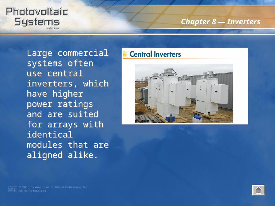
Large commercial systems often use central inverters, which have higher power ratings and are suited for arrays with identical modules that are aligned alike.
Large commercial systems often use central inverters, which have higher power ratings and are suited for arrays with identical modules that are aligned alike.
Chapter 8 — InvertersChapter 8 — Inverters
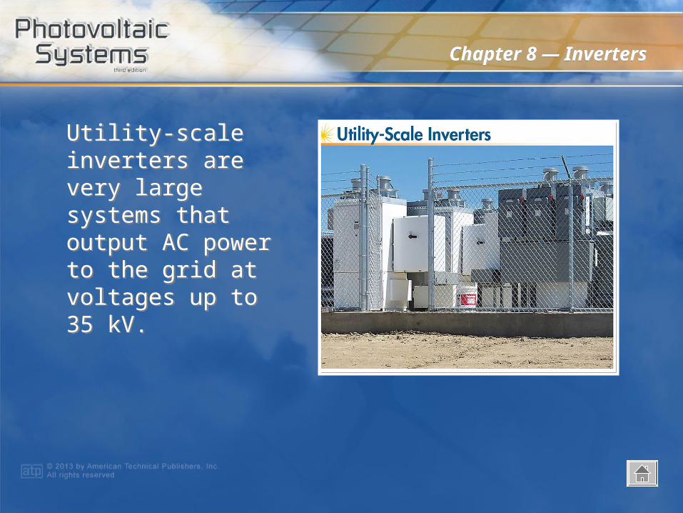
Utility-scale inverters are very large systems that output AC power to the grid at voltages up to 35 kV.
Utility-scale inverters are very large systems that output AC power to the grid at voltages up to 35 kV.
Chapter 8 — InvertersChapter 8 — Inverters
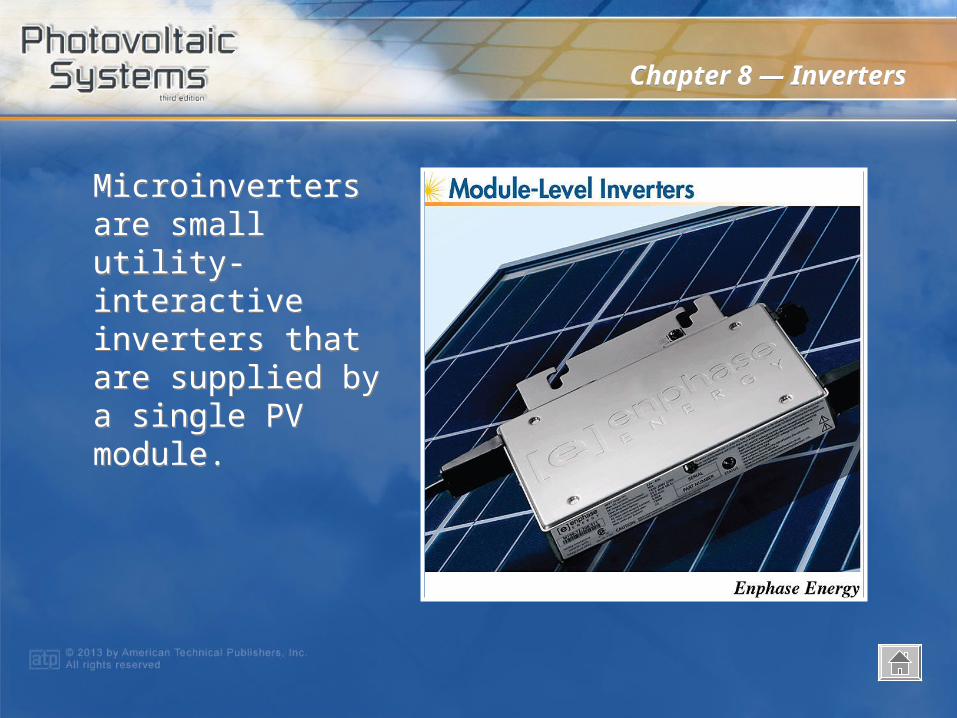
Microinverters are small utility-interactive inverters that are supplied by a single PV module.
Microinverters are small utility-interactive inverters that are supplied by a single PV module.
Chapter 8 — InvertersChapter 8 — Inverters
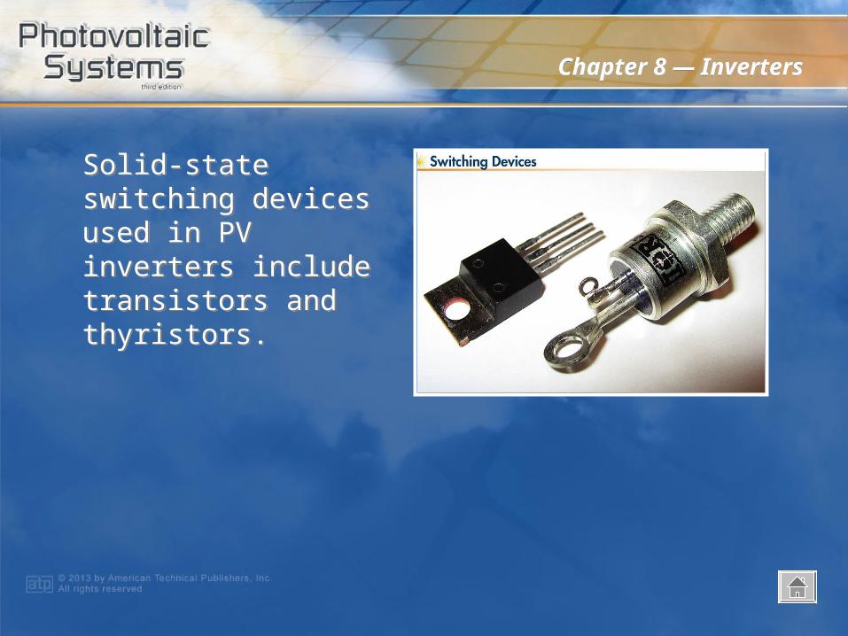
Solid-state switching devices used in PV inverters include transistors and thyristors.
Solid-state switching devices used in PV inverters include transistors and thyristors.
Chapter 8 — InvertersChapter 8 — Inverters
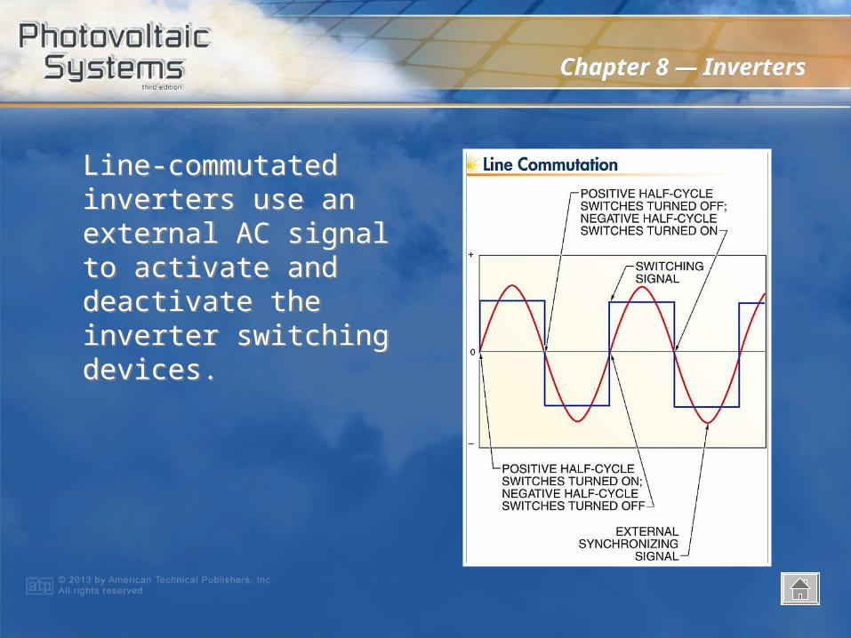
Line-commutated inverters use an external AC signal to activate and deactivate the inverter switching devices.
Line-commutated inverters use an external AC signal to activate and deactivate the inverter switching devices.

Chapter 8 — InvertersChapter 8 — Inverters
H-bridge inverter circuits use two pairs of switching devices to direct a DC input to the output in both directions.
H-bridge inverter circuits use two pairs of switching devices to direct a DC input to the output in both directions.
Chapter 8 — InvertersChapter 8 — Inverters
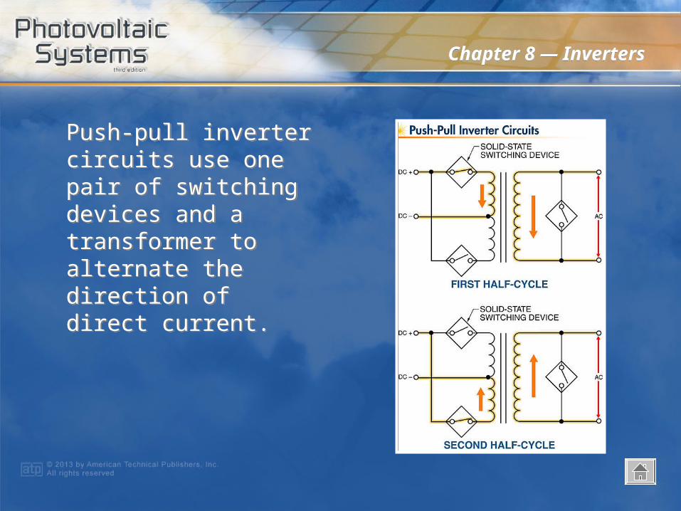
Push-pull inverter circuits use one pair of switching devices and a transformer to alternate the direction of direct current.
Push-pull inverter circuits use one pair of switching devices and a transformer to alternate the direction of direct current.
Chapter 8 — InvertersChapter 8 — Inverters
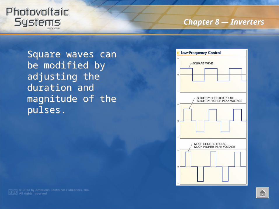
Square waves can be modified by adjusting the duration and magnitude of the pulses.
Square waves can be modified by adjusting the duration and magnitude of the pulses.

Chapter 8 — InvertersChapter 8 — Inverters
Combining multiple modified square waves with different magnitudes and durations results in a multistepped modified square wave that more closely approximates a sine wave.
Combining multiple modified square waves with different magnitudes and durations results in a multistepped modified square wave that more closely approximates a sine wave.
Chapter 8 — InvertersChapter 8 — Inverters
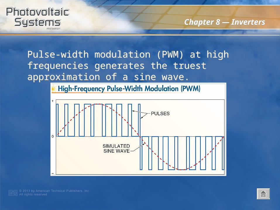
Pulse-width modulation (PWM) at high frequencies generates the truest approximation of a sine wave.Pulse-width modulation (PWM) at high frequencies generates the truest approximation of a sine wave.
Chapter 8 — InvertersChapter 8 — Inverters
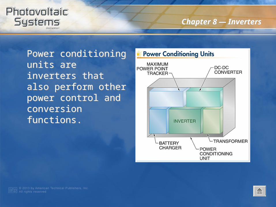
Power conditioning units are inverters that also perform other power control and conversion functions.
Power conditioning units are inverters that also perform other power control and conversion functions.
Chapter 8 — InvertersChapter 8 — Inverters
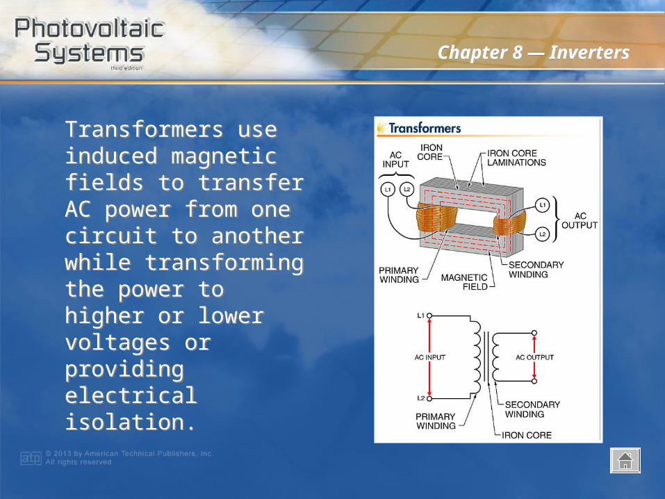
Transformers use induced magnetic fields to transfer AC power from one circuit to another while transforming the power to higher or lower voltages or providing electrical isolation.
Transformers use induced magnetic fields to transfer AC power from one circuit to another while transforming the power to higher or lower voltages or providing electrical isolation.
Chapter 8 — InvertersChapter 8 — Inverters
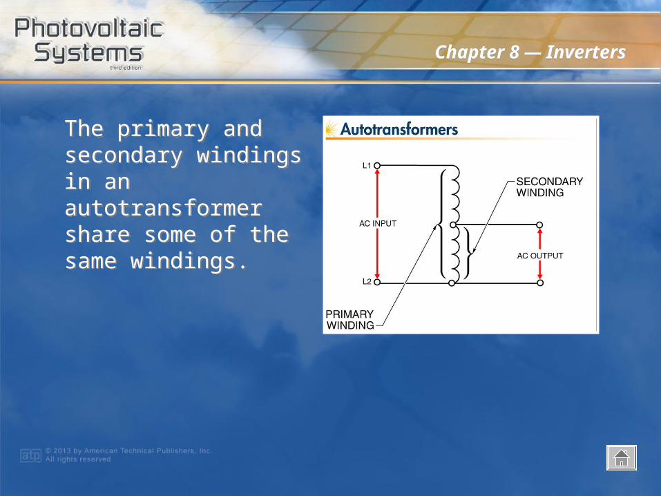
The primary and secondary windings in an autotransformer share some of the same windings.
The primary and secondary windings in an autotransformer share some of the same windings.
Chapter 8 — InvertersChapter 8 — Inverters
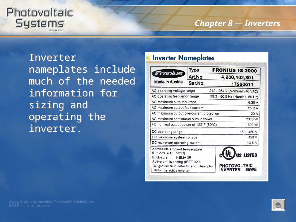
Inverter nameplates include much of the needed information for sizing and operating the inverter.
Inverter nameplates include much of the needed information for sizing and operating the inverter.

Chapter 8 — InvertersChapter 8 — Inverters
At high temperatures, an interactive inverter may limit current input by raising the input voltage, which also lowers power input and output.
At high temperatures, an interactive inverter may limit current input by raising the input voltage, which also lowers power input and output.

Chapter 8 — InvertersChapter 8 — Inverters
Most inverters operate from a relatively wide range of input voltages, but the range for MPPT operation is usually smaller.
Most inverters operate from a relatively wide range of input voltages, but the range for MPPT operation is usually smaller.
Chapter 8 — InvertersChapter 8 — Inverters
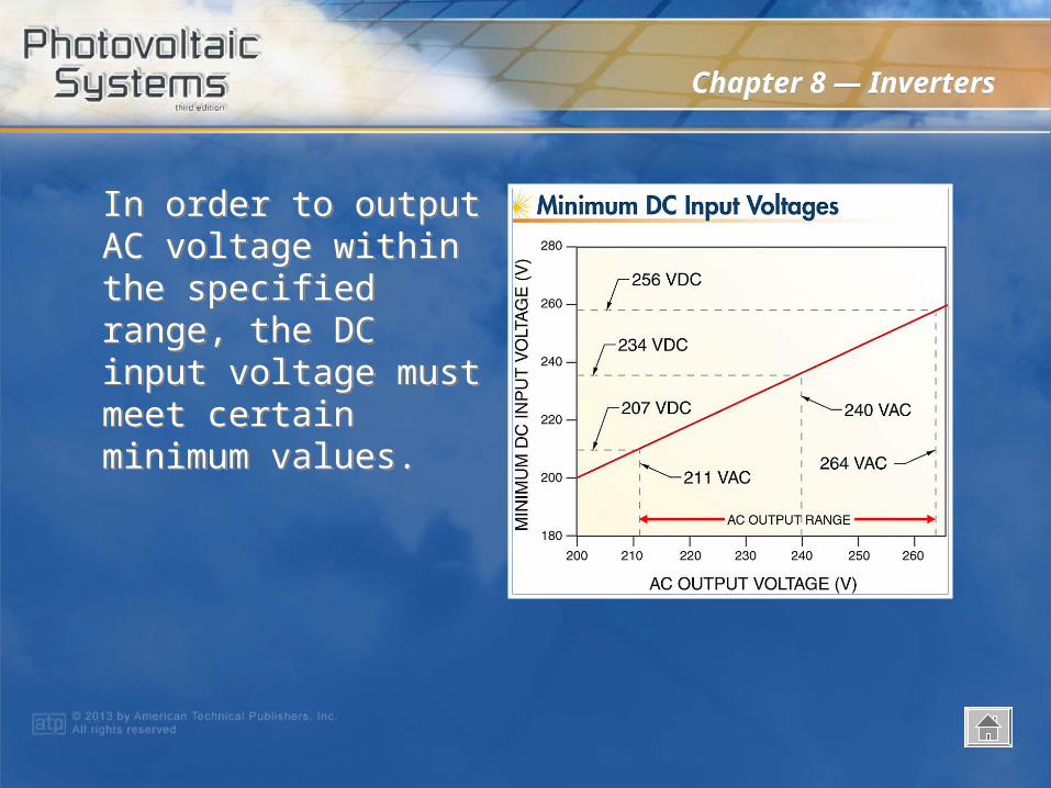
In order to output AC voltage within the specified range, the DC input voltage must meet certain minimum values.
In order to output AC voltage within the specified range, the DC input voltage must meet certain minimum values.
Chapter 8 — InvertersChapter 8 — Inverters
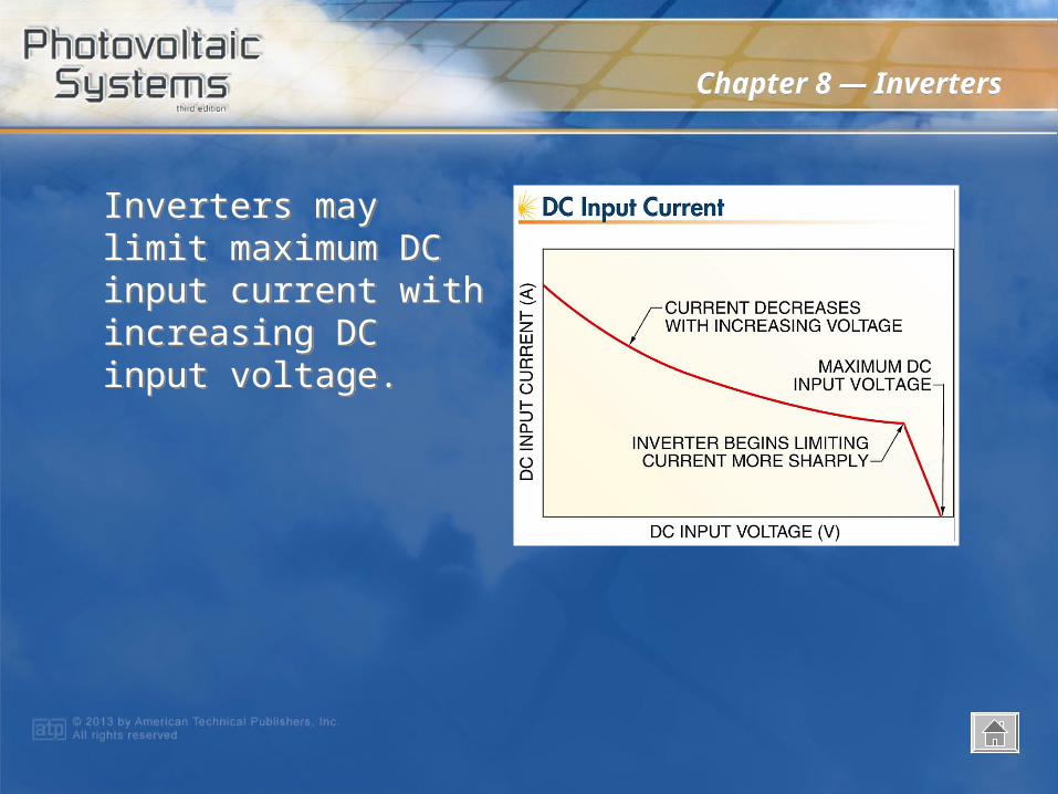
Inverters may limit maximum DC input current with increasing DC input voltage.
Inverters may limit maximum DC input current with increasing DC input voltage.

Chapter 8 — InvertersChapter 8 — Inverters
Most sine wave inverters maintain high efficiency over a wide operating-power range.
Most sine wave inverters maintain high efficiency over a wide operating-power range.
Chapter 8 — InvertersChapter 8 — Inverters
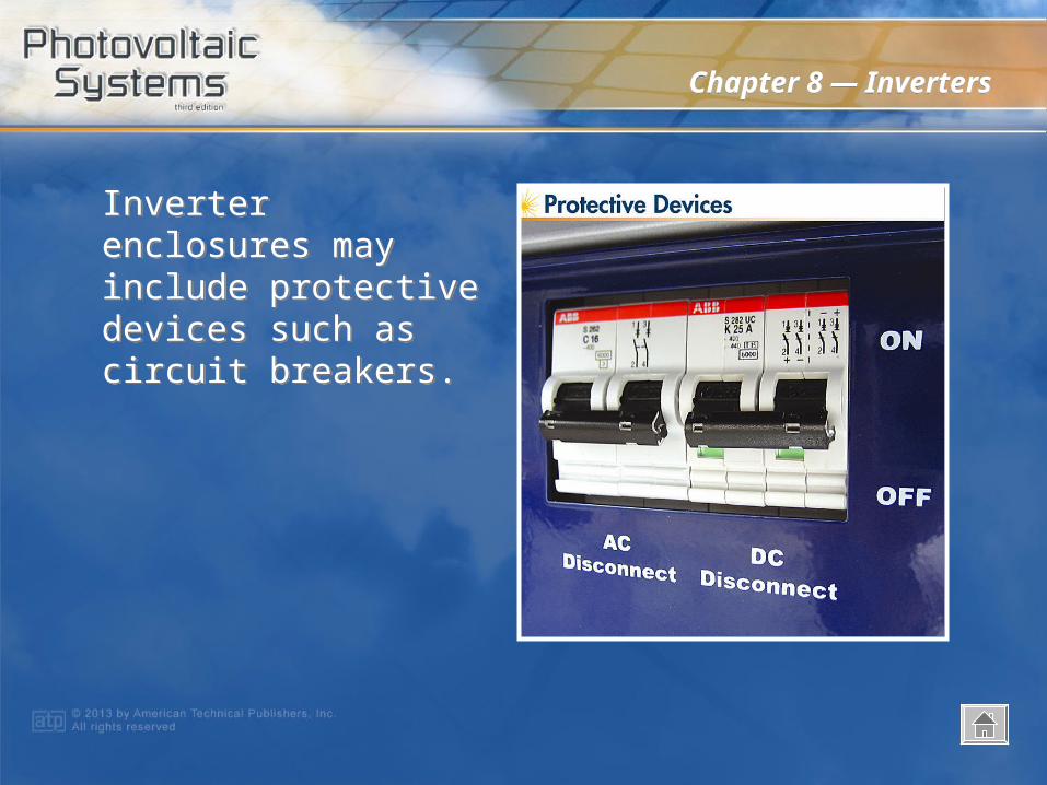
Inverter enclosures may include protective devices such as circuit breakers.
Inverter enclosures may include protective devices such as circuit breakers.

Chapter 8 — InvertersChapter 8 — Inverters
Inverter interfaces include on-board screens, remote data monitors, and computerized data acquisition and processing software.
Inverter interfaces include on-board screens, remote data monitors, and computerized data acquisition and processing software.