Embed Size (px)
Citation preview
User & Installation Manual
Power Supply Inteface Module (PSIM)
Information in this document is subject to change without notice. Companies, names and data usedin examples herein are fictitious unless noted otherwise. No part of this document may be reproduced or transmitted in any form or by means, electronic or mechanical, for any purpose, without the express permission of Solartron Metrology.
© 2001 Solartron Metrology. All rights reserved.
Orbit is a trademark of Solartron MetrologyAll other brand names, product names or trademarks belong to their respective holders.
Part No. 501622 Issue 8.1
Index
Index 1Part No. 501622 Issue 8.1
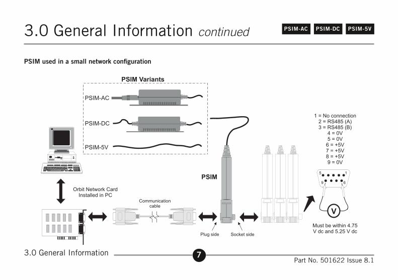
PSIM-AC PSIM-DC PSIM-5V
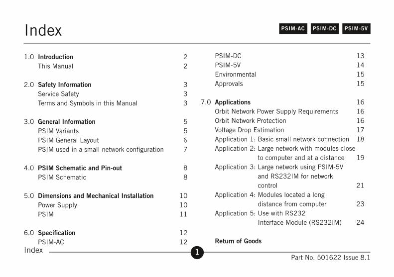
1.0 Introduction 2 This Manual 2
2.0 Safety Information 3 Service Safety 3 Terms and Symbols in this Manual 3
3.0 General Information 5 PSIM Variants 5 PSIM General Layout 6 PSIM used in a small network configuration 7
4.0 PSIM Schematic and Pin-out 8 PSIM Schematic 8
5.0 Dimensions and Mechanical Installation 10 Power Supply 10 PSIM 11
6.0 Specification 12 PSIM-AC 12
PSIM-DC 13 PSIM-5V 14 Environmental 15 Approvals 15
7.0 Applications 16 Orbit Network Power Supply Requirements 16 Orbit Network Protection 16 Voltage Drop Estimation 17 Application 1: Basic small network connection 18 Application 2: Large network with modules close
to computer and at a distance 19 Application 3: Large network using PSIM-5V
and RS232IM for network control 21
Application 4: Modules located a long distance from computer 23
Application 5: Use with RS232 Interface Module (RS232IM) 24
Return of Goods
2Part No. 501622 Issue 8.1
PSIM-AC PSIM-DC PSIM-5V
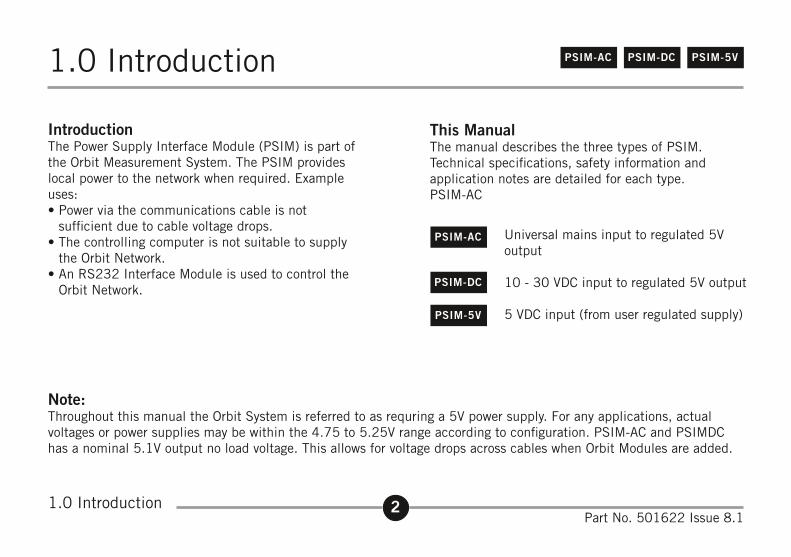
This ManualThe manual describes the three types of PSIM.Technical specifications, safety information and application notes are detailed for each type.PSIM-AC
Universal mains input to regulated 5V output
10 - 30 VDC input to regulated 5V output
5 VDC input (from user regulated supply)
1.0 Introduction
1.0 Introduction
IntroductionThe Power Supply Interface Module (PSIM) is part of the Orbit Measurement System. The PSIM provides local power to the network when required. Example uses:• Power via the communications cable is not
sufficient due to cable voltage drops.• The controlling computer is not suitable to supply
the Orbit Network.• An RS232 Interface Module is used to control the
Orbit Network.
PSIM-AC
PSIM-DC
PSIM-5V
Note:Throughout this manual the Orbit System is referred to as requring a 5V power supply. For any applications, actual voltages or power supplies may be within the 4.75 to 5.25V range according to configuration. PSIM-AC and PSIMDC has a nominal 5.1V output no load voltage. This allows for voltage drops across cables when Orbit Modules are added.
3Part No. 501622 Issue 8.1
PSIM-AC PSIM-DC PSIM-5V2.0 Safety Information
2.0 Safety Information
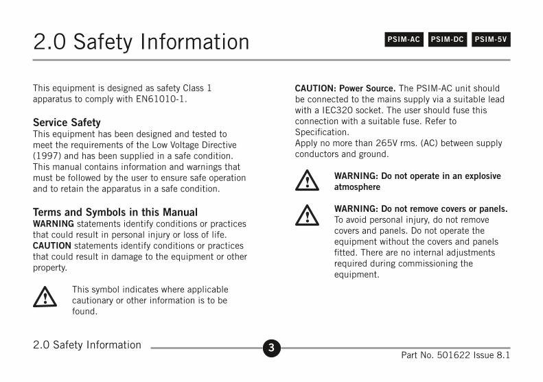
This equipment is designed as safety Class 1 apparatus to comply with EN61010-1.
Service SafetyThis equipment has been designed and tested to meet the requirements of the Low Voltage Directive (1997) and has been supplied in a safe condition. This manual contains information and warnings that must be followed by the user to ensure safe operation and to retain the apparatus in a safe condition.
Terms and Symbols in this ManualWARNING statements identify conditions or practicesthat could result in personal injury or loss of life.CAUTION statements identify conditions or practicesthat could result in damage to the equipment or otherproperty.
This symbol indicates where applicable cautionary or other information is to be found.
CAUTION: Power Source. The PSIM-AC unit shouldbe connected to the mains supply via a suitable leadwith a IEC320 socket. The user should fuse thisconnection with a suitable fuse. Refer to Specification.Apply no more than 265V rms. (AC) between supplyconductors and ground.
WARNING: Do not operate in an explosive atmosphere
WARNING: Do not remove covers or panels. To avoid personal injury, do not remove covers and panels. Do not operate the equipment without the covers and panels fitted. There are no internal adjustments required during commissioning the equipment.
4Part No. 501622 Issue 8.1
PSIM-AC PSIM-DC PSIM-5V2.0 Safety Information continued
WARNING: Danger arising from loss of ground. During a fault condition and upon loss of protective ground (earth), all accessible conducting parts - including controls that might appear to be insulated - can render an electric shock.
WARNING: Grounding the equipment. The unit is grounded through the mains lead: to avoid electric shock, plug the power lead into a properly-wired receptacle before connecting to the input or output terminals. A protective ground connection by way of the grounding conductor in the power lead is essential for safe operation.
CAUTION This equipment contains no user serviceable parts. This equipment must be returned to a Solartron Dealer for all service and repair. Dismantling the unit will invalidate the warranty.
CAUTION To avoid a fire hazard, use the correct fuse type, voltage and current rating as specified for the equipment. Refer fuse replacement to qualified personnel.
2.0 Safety Information
5Part No. 501622 Issue 8.1
PSIM-AC PSIM-DC PSIM-5V3.0 General Information
3.0 General Information
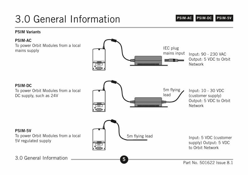
PSIM-ACTo power Orbit Modules from a local mains supply
PSIM-DCTo power Orbit Modules from a local DC supply, such as 24V
PSIM-5VTo power Orbit Modules from a local 5V regulated supply
PSIM Variants
IEC plugmains input Input: 90 - 230 VAC
Output: 5 VDC to Orbit Network
Input: 10 - 30 VDC (customer supply)Output: 5 VDC to Orbit Network
Input: 5 VDC (customer supply) Output: 5 VDC to Orbit Network
5m flying lead
5m flying lead
6Part No. 501622 Issue 8.1
PSIM-AC PSIM-DC PSIM-5V3.0 General Information continued
3.0 General Information
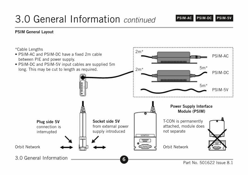
*Cable Lengths• PSIM-AC and PSIM-DC have a fixed 2m cable
between PIE and power supply.• PSIM-DC and PSIM-5V input cables are supplied 5m
long. This may be cut to length as required.
2m*
5m*
PSIM-AC
PSIM-DC
PSIM-5V
2m*
5m*
Plug side 5Vconnection isinterrupted
Socket side 5Vfrom external powersupply introduced
T-CON is permanentlyattached, module doesnot separate
Orbit Network Orbit Network
PSIM General Layout
Power Supply InterfaceModule (PSIM)
7Part No. 501622 Issue 8.1
PSIM-AC PSIM-DC PSIM-5V3.0 General Information continued
PSIM used in a small network configuration
3.0 General Information
8Part No. 501622 Issue 8.1
PSIM-AC PSIM-DC PSIM-5V4.0 PSIM Schematic and Pin-out
4.0 PSIM Schematic and Pin-out
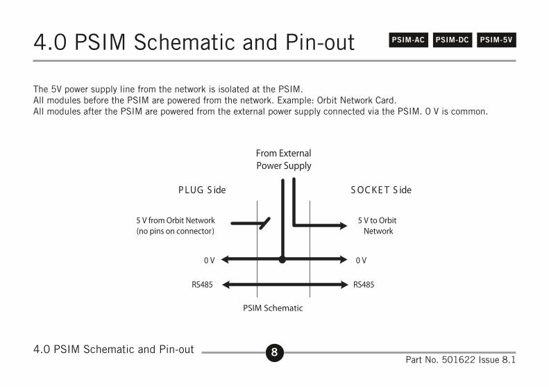
The 5V power supply line from the network is isolated at the PSIM.All modules before the PSIM are powered from the network. Example: Orbit Network Card.All modules after the PSIM are powered from the external power supply connected via the PSIM. 0 V is common.
9Part No. 501622 Issue 8.1
PSIM-AC PSIM-DC PSIM-5V
4.0 PSIM Schematic and Pin-out
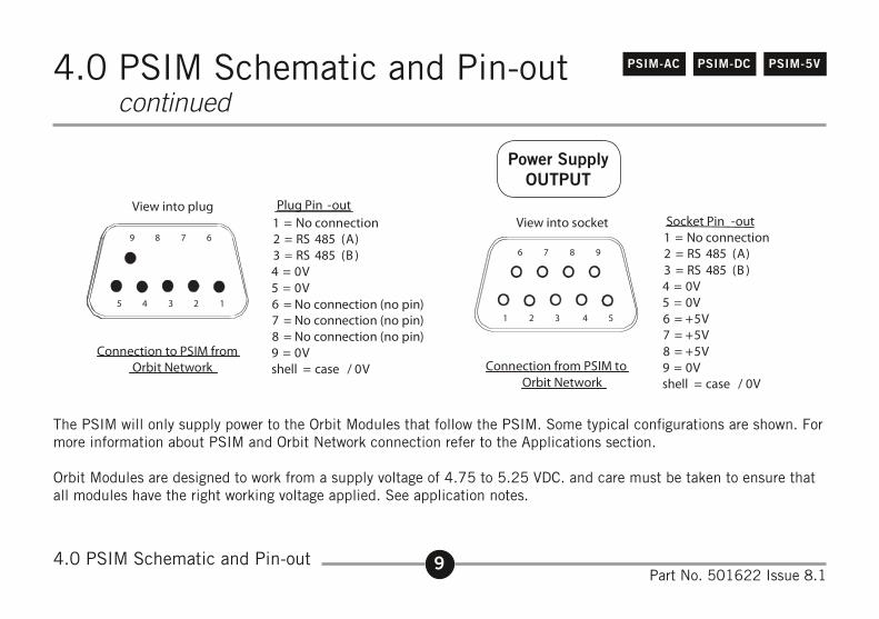
The PSIM will only supply power to the Orbit Modules that follow the PSIM. Some typical configurations are shown. For more information about PSIM and Orbit Network connection refer to the Applications section.
Orbit Modules are designed to work from a supply voltage of 4.75 to 5.25 VDC. and care must be taken to ensure that all modules have the right working voltage applied. See application notes.
4.0 PSIM Schematic and Pin-out continued
10Part No. 501622 Issue 8.1
PSIM-5VPSIM-AC PSIM-DC5.0 Dimensions and Mechanical Installation
5.0 Dimensions and Mechanical Installation
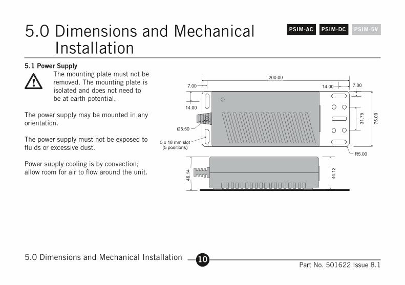
5.1 Power Supply The mounting plate must not be
removed. The mounting plate is isolated and does not need to be at earth potential.
The power supply may be mounted in any orientation.
The power supply must not be exposed to fluids or excessive dust.
Power supply cooling is by convection; allow room for air to flow around the unit.
11Part No. 501622 Issue 8.1
PSIM-AC PSIM-DC PSIM-5V
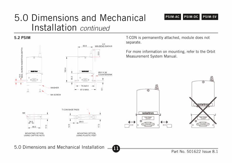
5.2 PSIM
5.0 Dimensions and Mechanical Installation
T-CON is permanently attached, module does not separate.
For more information on mounting, refer to the Orbit Measurement System Manual.
5.0 Dimensions and Mechanical Installation continued
12Part No. 501622 Issue 8.1
PSIM-5VPSIM-DCPSIM-AC
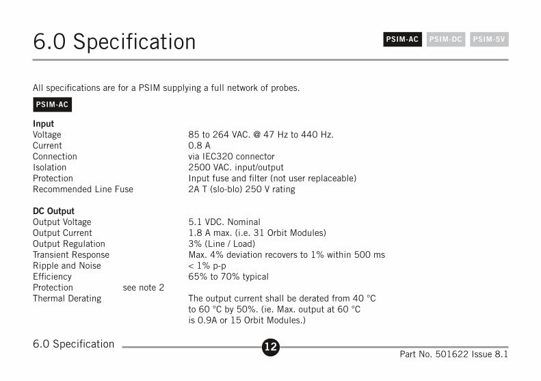
InputVoltage 85 to 264 VAC. @ 47 Hz to 440 Hz.Current 0.8 AConnection via IEC320 connectorIsolation 2500 VAC. input/outputProtection Input fuse and filter (not user replaceable)Recommended Line Fuse 2A T (slo-blo) 250 V rating
DC OutputOutput Voltage 5.1 VDC. NominalOutput Current 1.8 A max. (i.e. 31 Orbit Modules)Output Regulation 3% (Line / Load)Transient Response Max. 4% deviation recovers to 1% within 500 msRipple and Noise < 1% p-pEfficiency 65% to 70% typicalProtection see note 2Thermal Derating The output current shall be derated from 40 °C
to 60 °C by 50%. (ie. Max. output at 60 °C is 0.9A or 15 Orbit Modules.)
All specifications are for a PSIM supplying a full network of probes.
6.0 Specification
6.0 Specification
PSIM-AC
13Part No. 501622 Issue 8.1
PSIM-DC PSIM-5VPSIM-AC6.0 Specification continued
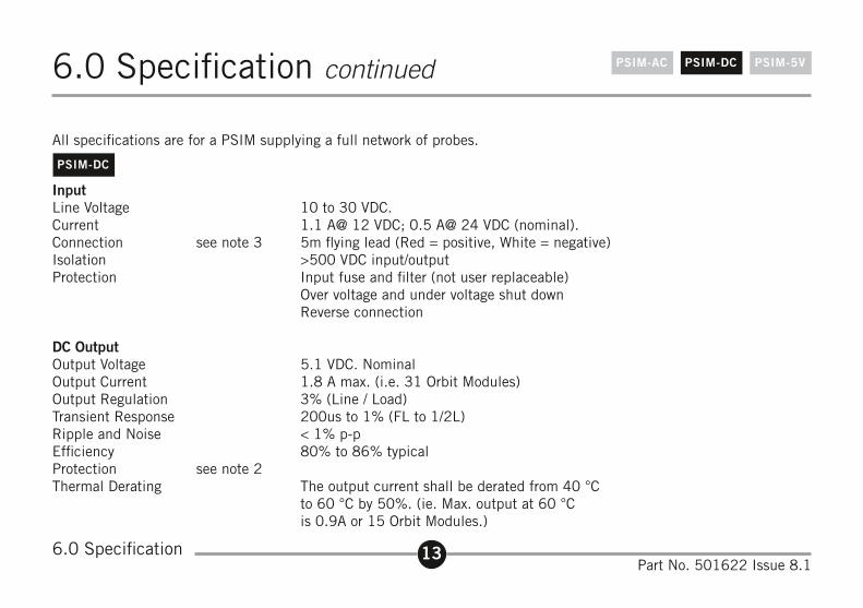
InputLine Voltage 10 to 30 VDC.Current 1.1 A@ 12 VDC; 0.5 A@ 24 VDC (nominal).Connection see note 3 5m flying lead (Red = positive, White = negative)Isolation >500 VDC input/outputProtection Input fuse and filter (not user replaceable)
Over voltage and under voltage shut down Reverse connection
DC OutputOutput Voltage 5.1 VDC. NominalOutput Current 1.8 A max. (i.e. 31 Orbit Modules)Output Regulation 3% (Line / Load)Transient Response 200us to 1% (FL to 1/2L)Ripple and Noise < 1% p-pEfficiency 80% to 86% typicalProtection see note 2Thermal Derating The output current shall be derated from 40 °C
to 60 °C by 50%. (ie. Max. output at 60 °C is 0.9A or 15 Orbit Modules.)
All specifications are for a PSIM supplying a full network of probes.
PSIM-DC
6.0 Specification
14Part No. 501622 Issue 8.1
PSIM-5VPSIM-DCPSIM-AC6.0 Specification continued
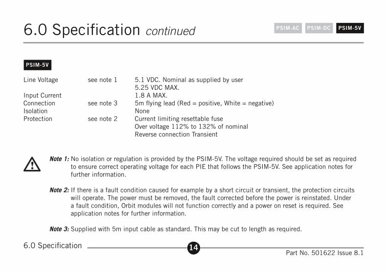
Line Voltage see note 1 5.1 VDC. Nominal as supplied by user 5.25 VDC MAX.
Input Current 1.8 A MAX.Connection see note 3 5m flying lead (Red = positive, White = negative)Isolation NoneProtection see note 2 Current limiting resettable fuse
Over voltage 112% to 132% of nominal Reverse connection Transient
Note 1: No isolation or regulation is provided by the PSIM-5V. The voltage required should be set as required to ensure correct operating voltage for each PIE that follows the PSIM-5V. See application notes for further information.
Note 2: If there is a fault condition caused for example by a short circuit or transient, the protection circuits will operate. The power must be removed, the fault corrected before the power is reinstated. Under a fault condition, Orbit modules will not function correctly and a power on reset is required. See application notes for further information.
Note 3: Supplied with 5m input cable as standard. This may be cut to length as required.
PSIM-5V
6.0 Specification
15Part No. 501622 Issue 8.1
PSIM-AC PSIM-DC PSIM-5V6.0 Specification continued
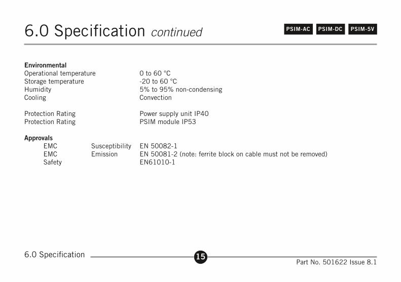
EnvironmentalOperational temperature 0 to 60 °CStorage temperature -20 to 60 °CHumidity 5% to 95% non-condensingCooling Convection
Protection Rating Power supply unit IP40Protection Rating PSIM module IP53
ApprovalsEMC Susceptibility EN 50082-1EMC Emission EN 50081-2 (note: ferrite block on cable must not be removed)Safety EN61010-1
6.0 Specification
16Part No. 501622 Issue 8.1
PSIM-AC PSIM-DC PSIM-5V7.0 Applications
7.0 Applications
Orbit Network Power Supply RequirementsAll Orbit Modules are designed to work from a supply voltage of 4.75V to 5.25 VDC. When power is applied to a module, its current consumption will cause a slight voltage drop across cables. Care must be taken to ensure that all modules have the right working voltage applied.
This section is for guidance only. Since every application is different it is not possible to give precise information that covers all installations. Your Solartron dealer will be able to provide further advice if required.
Note:Throughout this manual the Orbit System is referred to as requring a 5V power supply. For any applications, actual voltages or power supplies may be within the 4.75 to 5.25V range according to configuration. PSIM-AC and PSIM-DC has a nominal 5.1V output no load voltage. This allows for voltage drops across cables when Orbit Modules are added.
Orbit Network ProtectionEach PSIM provides a high level of protection for an Orbit Network. Protection for mis-connection, over voltage and transients is provided.
If a transient or other over voltage occurs, the protection circuits will short circuit (crow bar) the power supply. At this time, the voltage levels to each Orbit Module will be below the working limit. When the fault condition has been removed, Orbit power must be removed and reapplied to allow a full hardware reset to take place. A software reset is not possible under these conditions.
17Part No. 501622 Issue 8.1
PSIM-AC PSIM-DC PSIM-5V7.0 Applications continued
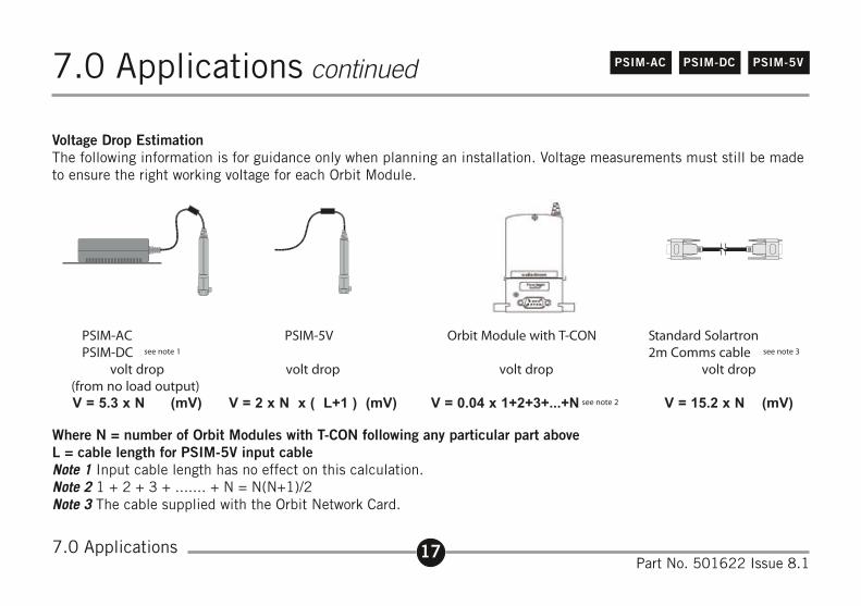
Voltage Drop EstimationThe following information is for guidance only when planning an installation. Voltage measurements must still be made to ensure the right working voltage for each Orbit Module.
Where N = number of Orbit Modules with T-CON following any particular part aboveL = cable length for PSIM-5V input cableNote 1 Input cable length has no effect on this calculation.Note 2 1 + 2 + 3 + ....... + N = N(N+1)/2Note 3 The cable supplied with the Orbit Network Card.
7.0 Applications
18Part No. 501622 Issue 8.1
PSIM-AC PSIM-DC PSIM-5V7.0 Applications continued
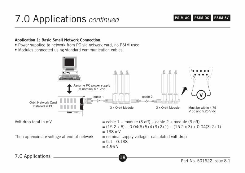
Application 1: Basic Small Network Connection.• Power supplied to network from PC via network card, no PSIM used.• Modules connected using standard communication cables.
Volt drop total in mV = cable 1 + module (3 off) + cable 2 + module (3 off) = (15.2 x 6) + 0.04(6+5+4+3+2+1) + (15.2 x 3) + 0.04(3+2+1) = 138 mVThen approximate voltage at end of network = nominal supply voltage - calculated volt drop = 5.1 - 0.138 = 4.96 V
7.0 Applications
19Part No. 501622 Issue 8.1
PSIM-AC PSIM-DC PSIM-5V7.0 Applications continued
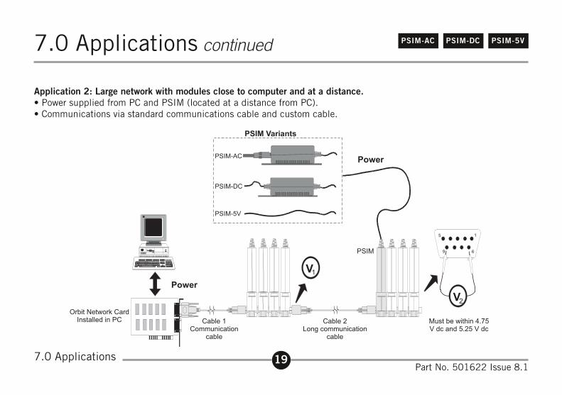
Application 2: Large network with modules close to computer and at a distance.• Power supplied from PC and PSIM (located at a distance from PC).• Communications via standard communications cable and custom cable.
7.0 Applications
20Part No. 501622 Issue 8.1
PSIM-AC PSIM-DC PSIM-5V7.0 Applications continued
Volt drop V1 is calculated in a similar way to the previous example except there is only a single cable and 3 Orbit modules. The PSIM supplies power to remaining modules and are calculated separately. The long communications cable does not carry supply current and so has no affect on volt drops.
Calculation for V1 volt drop = cable + module (3 off) = (15.2 x 3) + 0.04(3+2+1) = 46 mVThen approximate voltage at end of network = nominal supply voltage - calculated volt drop = 5.1 - 0.046 = 5.054 Vi.e. greater than 4.75 VDC the minimum working voltage
Calculation for V2 volt drop = PSIM + module (3 off) = (5.3 x 3) + 0.04(3+2+1) = 16 mV
Then approximate voltage at end of network = nominal supply voltage - calculated volt drop = 5.1 - 0.016 = 5.084 V
i.e. greater than 4.75 VDC the minimum working voltage.
7.0 Applications
21Part No. 501622 Issue 8.1
PSIM-5VPSIM-DCPSIM-AC7.0 Applications continued
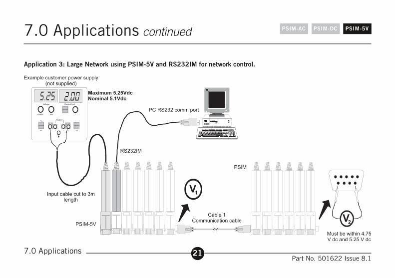
Application 3: Large Network using PSIM-5V and RS232IM for network control.
7.0 Applications
22Part No. 501622 Issue 8.1
PSIM-5VPSIM-DCPSIM-AC7.0 Applications continued
The PSIM-5V is powering the whole Orbit Network. PSIM-5V volt drop is calculated using 12 as the total number of Orbit modules; the RS232IM is included in this number.
Total Voltage drop = PSIM-5V + modules (6 off) + Cable 1 + Modules (6 off) = (2 x 12 x [3+1]) + 0.04 (1+2+3+4+5+6+7+8+9+10+11+12)+ (15.2 x 6) + 0.04
(1+2+3+4+5+6) = 96 + 3.12 + 91.2 + 0.84 = 191 mV
Then approximate voltage at end of network = nominal supply voltage - calculated volt drop = 5.25 - 0.191 = 5.06 V
i.e. greater than 4.75 VDC the minimum working voltage. In this example the input supply to the PSIM-5V could be reduced to 5.1 V (the Orbit nominal value).
7.0 Applications
23Part No. 501622 Issue 8.1
PSIM-AC PSIM-DC PSIM-5V7.0 Applications continued
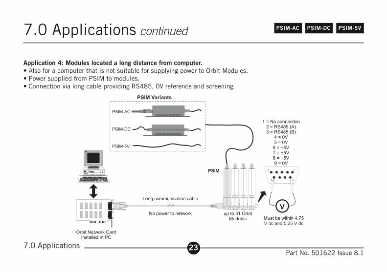
Application 4: Modules located a long distance from computer.• Also for a computer that is not suitable for supplying power to Orbit Modules.• Power supplied from PSIM to modules.• Connection via long cable providing RS485, 0V reference and screening.
7.0 Applications
24Part No. 501622 Issue 8.1
PSIM-AC PSIM-DC PSIM-5V7.0 Applications continued
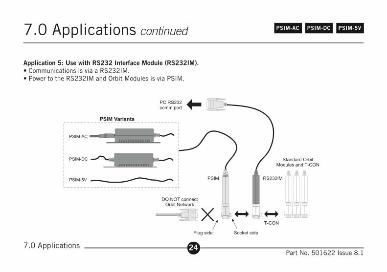
Application 5: Use with RS232 Interface Module (RS232IM).• Communications is via a RS232IM.• Power to the RS232IM and Orbit Modules is via PSIM.
7.0 Applications
Devices returned for service/repair/calibration should be shippedprepaid to your distributor or, if purchased directly from SolartronMetrology, to the relevant Sales Office (see overleaf).
The shipping container should be marked: "For the Attention ofthe Returns Department"
The following information should accompany the device(s):
1. Contact details of company/person returning device, including return shipping instructions.
2. A statement of service required and purchase order.
3. Description of the device fault and the circumstancesof the failure, including application environment andlength of time in service.
4. Original purchase order number and date ofpurchase, if known.
Please note: A standard assessment charge is applicable on allnon-warranty devices returned for repair. Customer damage andany device found, upon inspection, to have no fault will beconsidered non-warranty.
Please contact the Sales Office or Distributor for warranty terms,service options and standard charges.
Adherence to these procedures will expedite handling of the
returned device and will prevent unnecessary additional charges forinspection and testing to determine the condition.
Solartron Metrology reserves the right to repair or replace goodsreturned under warranty.
All repairs are guaranteed for 3 months (unless otherwise stated).
Solartron Metrology reserves the right to make changes withoutfurther notice to any products herein to improve reliability, function ordesign. Solartron Metrology does not assume any liability arising outof the application or use of any product or circuit described herein,neither does it convey any licence under patent rights nor the rights ofothers.
Return of Goods
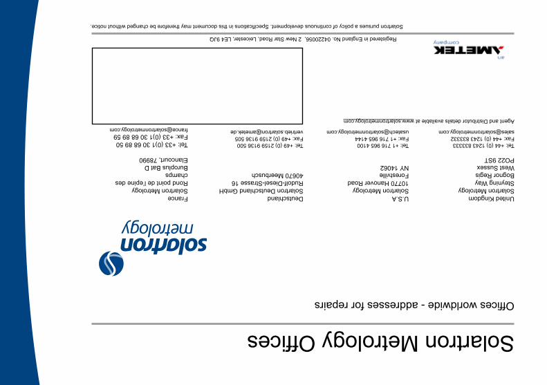
United KingdomSolartron MetrologySteyning WayBognor RegisWest SussexPO22 9ST
Tel: +44 (0) 1243 833333 Fax: +44 (0) 1243 [email protected]
Agent and Distributor details available at www.solartronmetrology.com
U.S.ASolartron Metrology10770 Hanover RoadForestvilleNY 14062
Tel: +1 716 965 4100 Fax: +1 716 965 [email protected]
DeutschlandSolartron Deutschland GmbHRudolf-Diesel-Strasse 1640670 Meerbusch
Tel: +49 (0) 2159 9136 500 Fax: +49 (0) 2159 9136 [email protected]
FranceSolartron MetrologyRond point de l’epine des champsBuroplus Bat DElancourt, 78990
Tel: +33 (0)1 30 68 89 50Fax: +33 (0)1 30 68 89 [email protected]
Solartron Metrology OfficesOffices worldwide - addresses for repairs
Solartron pursues a policy of continuous development. Specifications in this document may therefore be changed without notice.
Registered in England No. 04220056, 2 New Star Road, Leicester, LE4 9JQ


![Psim Manual[1]](https://img.dokumen.tips/doc/110x75/552735384979595f178b45f9/psim-manual1.jpg)


