Embed Size (px)
DESCRIPTION
Polymer Surfactant assisted EOR
Citation preview
2
The Application of a New Polymeric Surfactant for Chemical EOR
Khaled Abdalla Elraies and Isa M. Tan Universiti Teknologi PETRONAS, Ipoh
Malaysia
1. Introduction
Crude oil makes a major contribution to the world economy today. The provision of heat, light, and transportation depends on oil and there has not been yet a single energy source to replace crude oil that is widely integrated. Moreover, the global economy currently depends on the ability to acquire the energy required and it is indisputable that oil is the main contributor to this demand. Currently, there is no an energy source available that could compete with oil, making the world, and mainly the high energy consumers to rely on countries with large reserves (Energy Information Administration, 2003).
Traditionally oil production strategies have followed primary depletion, secondary recovery, and tertiary recovery processes. Primary depletion uses the natural reservoir energy to accomplish the displacement of oil from the porous rocks to the producing wells (Craft et al., 1991). An average of 10 to 20 percent of original oil in place (OOIP) can be recovered through primary recovery. Secondary recovery methods are processes in which the oil is subjected to immiscible displacement with injected fluids such as water or gas. It is estimated that about thirty to fifty percent of the OOIP can be produced through the entire life of a mature reservoir that has been developed under primary and secondary recovery methods (Green & Willhite, 1998). The remaining oil is still trapped in the porous media. This is attributed to surface and interfacial forces (capillary forces), viscosity forces, and reservoir heterogeneities which results in poor displacement efficiency (Green & Willhite, 1998). Recognition of these facts has led to the development and use of many enhanced oil recovery (EOR) methods. EOR methods hold promise for recovering a significant portion of the remaining oil after conventional methods.
Planning for improving or enhancing oil production strategies through EOR methods is one of the most critical challenges facing the industry today. EOR not only will extend the life of this important non-renewable resource, but it will also delay a world production decline and shortage in the energy supply. Realizing the significant potential of EOR, most of oil companies embarked on a massive journey to advance EOR processes.
Various modifications of EOR methods have been developed to recover at least a portion of the remaining oil. Thermal processes are the most common type of EOR, where a hot invading phase, such as steam, hot water or a combustible gas, is injected in order to increase the temperature of oil and gas in the reservoir and facilitate their flow to the
www.intechopen.com

Introduction to Enhanced Oil Recovery (EOR) Processes and Bioremediation of Oil-Contaminated Sites
46
production wells (Green & Willhite, 1998). Another type of EOR process consists of injecting a miscible phase with the oil and gas into the reservoir to eliminate the interfacial tension effects. The miscible phase can be a hydrocarbon solvent, CO2, or an inert gas (N2). Another common EOR technique is chemical flooding which includes alkalis, surfactants, and polymers, or combinations thereof. The injected alkali and surfactant agents can lower interfacial tension (IFT) between oil and water, thereby mobilize the residual oil. Polymers are used to viscosify the aqueous solution for mobility control (Green & Willhite, 1998).
2. Chemical flooding for EOR
Chemical flooding, which has been developed since the early 1950s, is an important method for enhanced oil recovery that includes alkaline flooding, alkali-surfactant flooding, and alkali-surfactant-polymer flooding. Surfactant flooding and its variants are EOR processes that have been employed to recover the residual oil after primary and secondary recovery process.
The efficiency of the chemical EOR is a function of liquid viscosities, relative permeabilities, interfacial tensions, wettabilities, and capillary pressures (Liu, 2008). Even if all the oil is contacted by the injected chemicals, some oil would still remain in the reservoir. This is due to the trapping of oil droplets by capillary forces due to high interfacial tension (IFT) between water and oil (Liu, 2008). The capillary number (Nc) is used to express the forces acting on an entrapped droplet of oil within a porous media. Nc is a function of the Darcy velocity (v), the viscosity ( ) of the mobile phase, and the IFT ( ) between the mobile and the trapped oil phase (Berger & Lee, 2006). Equation 1 shows the relationship of Darcy velocity, viscosity and IFT to the capillary number.
/CN v (1)
Fig. 1. Capillary pressure curves for sandstone cores (Liu, 2008)
Figure 1 shows capillary desaturation curves that plot residual saturation of oil versus a capillary number on a logarithmic x-axis. From this figure, increasing capillary number reduces the residual oil saturation. The residual oil saturations for both the nonwetting and
No
rmali
zed
resi
du
al
satu
rati
on
Capillary number, Nc
www.intechopen.com

The Application of a New Polymeric Surfactant for Chemical EOR
47
the wetting cases are roughly constant at low capillary numbers. Above a certain capillary number, the residual saturation begins to decrease. This phenomenon indicates that large capillary number is beneficial to high recovery efficiency because the residual oil fraction becomes smaller. Capillary number must be increased in order to reduce the residual oil saturation. The most logical way to increase the capillary number is to reduce the IFT (Berger & Lee, 2006; Liu, 2008). Therefore, the principal objective of the chemical process is to lower the interfacial tension so that the recovery performance will be improved.
3. Surfactant in enhanced oil recovery
The concept of recovering oil by surfactant flooding dates back to 1929 when De Groot was granted a patent claiming water-soluble surfactants as an aid to improve oil recovery. The surfactant could reduce the interfacial tension between the brine and residual oil. The use of proper surfactant can effectively lower the IFT resulting in a corresponding increase in the capillary number (Berger & Lee, 2006). The success of surfactant flooding depends on many factors such as formulation, cost of surfactants, availability of chemicals, and oil prices in the market. In enhanced oil recovery, surfactants could be used in several formulations to enhance oil production. Some of these formulations are surfactant-alkali flooding, surfactant-polymer flooding, and alkali-surfactant-polymer flooding.
The idea of combining surfactants and alkalis was first proposed by Reisberg and Doscher in 1956. They added non-ionic surfactants to the alkali solution to improve oil recovery at laboratory scale. Recent work has shown that the addition of alkali to the surfactant solution would not only decrease the IFT, but also reduces the surfactant adsorption on the negatively charged sand surface (Touhami et al., 2001). An inexpensive alkali could be used with expensive surfactants to achieve both a technically successful and economically feasible flood.
In order to design an effective surfactant-alkali flooding formulation, it is important to utilize the synergistic effect between the surfactant and alkali. Surfactants tend to accumulate at the oil and water interface where the hydrophilic and hydrophobic ends of the molecules can be in a minimal energy state. This increases the surface pressure and decreases both the interfacial energy and the IFT. Rudin & Wasan (1992) concluded that the dominant mechanism of the synergistic effect is the formation of mixed micelles of the surfactants and the generated in situ surfactant. The mixed micelles cause the IFT to drop significantly (Nelson et al., 1984). At the same time, surfactant adsorption on sand is reduced by the presence of alkali. The sand surface will become increasingly negatively charged with an increase in pH and will thereby retard the adsorption of the anionic surfactant.
A number of alkali-surfactant flooding field tests have been described in the literature (Mayer et al., 1983; McCafferty and McClaflin, 1992). Success of these processes in an actual reservoir will depend on how well and for how long the internally-generated surfactant and the externally-added surfactant work together as intended. Mayer et al., (1983) summarized based on known field tests the amount of alkali injected and the performance results for early alkaline flooding processes. Most of the projects were not as profitable as expected. Falls et al., (1992) reported successful field tests using alkaline-surfactant flooding in recovering waterflood residual oil from sandstone reservoirs in the White Castle Field, USA. The process recovered at least 38% of the residual oil after waterflooding.
www.intechopen.com

Introduction to Enhanced Oil Recovery (EOR) Processes and Bioremediation of Oil-Contaminated Sites
48
Alkali-surfactant flooding is a promising method for enhanced oil recovery. With the combination of alkali and a small amount of surfactant, oil-water IFT can be reduced much more than with either alkali or surfactant alone. However, the recovery factor of this process is usually insufficient due to the unfavourable mobility ratio. Hence, a polymer is added to the surfactant solution to improve the sweep efficiency. The application of alkali-surfactant polymer in the Daqing oil field in China is an example of successful field trials. However, because of the high cost of surfactants, this process has not been expanded (Wang et al., 1997). In order to reduce the cost of the surfactant and to enlarge the swept volume, this technology was upgraded to alkali-surfactant-polymer flooding. The combination of alkali-surfactant-polymer is expected to cause the residual oil to be economically recovered from the reservoir.
Alkali-surfactant-polymer (ASP) is considered to be one of the major EOR techniques that can be successfully used in producing light and medium oils. The advantage of ASP flooding over conventional alkaline flooding is that ASP can be used for low acid number crudes while alkaline flooding can only be applied for medium to high acid number crudes. In the ASP process, alkali reacts with acidic oils to form in-situ surfactant and increases the pH to lower surfactant adsorption on the porous media. Surfactants are used to lower the IFT between oil and water while polymer is used to improve the sweep efficiency by providing mobility control (Elraies et al., 2010a). ASP flooding has been extensively evaluated in the laboratory and widely used in field applications with great success. In recent years, many ASP field pilot tests have been conducted in USA, India, Venezuela, and China (Pitts et al 2006; Pratap & Gauma, 2004; Clara et al 2001; Wang et al., 1999). The ASP process uses the benefits of the three flooding methods, and oil recovery is greatly enhanced by decreasing interfacial tension (IFT), increasing the capillary number, enhancing microscopic displacing efficiency, and improving the mobility ratio (Pingping et al., 2009). However, even with these advantages and the success of ASP projects, the process is not without some disadvantages.
An earlier paper written by Hou and co-workers (2001) addresses the corrosion and scale problems that occurred during the ASP flood in Daqing field. The strong alkali had detrimental effects on polymer performance and in many cases additional polymer was required to achieve the desired viscosity (Wang et al., 2006). Nasr-El-Din et al., (1992) conducted an experimental study to examine the effectiveness of alkali concentration in ASP performance. Their experiments confirmed an exponential decrease in viscosity of the combined ASP slug with the increase in alkali concentration.
The selection of proper surfactants is one of the key factors for chemical EOR application. Surfactant should be stable under reservoir conditions resulting in an ultra low interfacial tension. Wangqi & Dave, (2004) conducted screening studied by interfacial tension experiments using different types of surfactants and validated by core flood tests. The IFT results showed wide range of IFT reduction, depends on the surfactant concentration and type. Core flood results indicated that 11.2% OOIP could be recovered when the selected surfactant concentration and type are combined with alkali and polymer. Flaaten et al., 2008 performed the screening and optimization of surfactant formulations by microemulsion phase behavior using various combinations of surfactants, co-solvents, and alkalis. Branched alcohol propoxy sulfates and internal olefin sulfonates demonstrated a superior performance when mixed with conventional alkali. The recovery performance indicated that nearly 100% of residual oil was recovered with very low surfactant adsorption.
www.intechopen.com
The Application of a New Polymeric Surfactant for Chemical EOR
49
4. Chemical EOR challenges
Most pilot tests reported in the 2000s accomplished a higher oil recovery than those in the 1970s and 1980s. Improvements in the functionality of the chemicals and a better understanding of the process mechanisms are the causes for these successes. These field tests indicate that surfactant flooding and its variants can be technically successful. However, the main downside for these chemical EOR applications was still the high manufacture cost of surfactants and the cost of raw materials. The recovered oil by this process was not economical or the economical and technical risk was too high compared with the oil price (Austad & Milter, 2000). Therefore, a lot of work has been recently conducted to develop an economical surfactant when the crude oil prices remained high. To reduce the cost of surfactant production, much attention is focused toward agriculturally derived oleochemicals as alternative feedstocks (Gregorio, 2005). Many surfactants have been produced from natural oils to satisfy EOR requirements (Wuest et al., 1994; Li et al., 2000). Soybean and coconut oils are the most popular raw materials used to derive oleochemical feedstocks such as fatty alcohol and esters (Hill, 2000).
Paradoxically, these surfactants use edible vegetable oils for its synthesis and it will compete with the food supply in the long-term. As the demand and cost of edible vegetable oils has increased annually in recent years, then their derivative surfactant becomes more expensive (Gregorio, 2005). According to the United States Department of Agriculture Oilseeds 2009, the average cost of soybean oil was approximately $ 395 per tonne at the time. While, the cost of non-edible oils such as Jatropha oil was about $ 250 per tonne and the typical cost of the major petrochemical feedstock such as ethylene was $ 595 per tonne. Therefore, the evaluation and production of Jatropha oil based surfactant was an attractive pursuit for chemical EOR.
5. Development of a new polymeric surfactant
This section of the chapter is focused on the description of the development of a new polymeric surfactant with the aim to overcome some of the existing problems associated with conventional ASP flooding. The goal is to produce a new surfactant that will be both economical and effective for interfacial tension reduction and viscosity control. The basic idea was to attach the sulfonate group to a hydrophobic group of an associative polymer chain. A hydrophobically modified polymer is one class of water soluble associative polymer that contains a small number of hydrophobic groups (Abdala, 2002). Hydrophobically modified polymers have either a telechelic structure in which the chains are end-capped with the hydrophobic groups, or more complicated comb-like structures in which the hydrophobic groups are randomly grafted to the polymer backbone. The backbone has a polyelectrolyte feature and is composed of a polymer of acrylamide or acrylic acid, and ethylacrylate. Upon neutralization, the polymer backbone adopts a more extended conformation allowing the hydrophobic groups to associate forming a transient network structure (Abdala, 2002).
Herein, a single step route that is similar to the method reported by Ye et al., (2004) was used to produce a new polymeric surfactant via the polymerization process. This surfactant was designed to graft the sulfonated group to the polymer backbone as one component system for interfacial tension reduction and viscosity control. Therefore, the polymerization
www.intechopen.com

Introduction to Enhanced Oil Recovery (EOR) Processes and Bioremediation of Oil-Contaminated Sites
50
was conducted with an excess of different surfactant to acrylamide ratios. Sodium methyl ester sulfonate (SMES) was used as a surfactant feedstock in the polymerization process. Because the goal was to design a cost effective surfactant, the SMES was synthesized from Jatropha oil as the raw material. Jatropha oil was selected because it is a non-edible oil so it will not compete with food supply and it is not a petroleum derivative. Finally, it is a drought resistant perennial tree that grows in marginal lands and can live over 50 years. Under these conditions, it is expected that the supply and availability of Jatropha oil will not be a major concern.
6. Jatropha oil
Jatropha curcas L. is a plant belonging to the Euphorbiaceae family that produces a significant amount of oil from its seeds. This is a non-edible oil-bearing plant widespread in arid, semi-arid, and tropical regions of the world. Jatropha is a drought resistant perennial tree that grows in marginal lands and can live over 50 years (Bosswell, 2003). Jatropha oil content varies depending on the types of species and climatic conditions, but mainly on the altitude where it is grown (Pant et al., 2006). The oil content in Jatropha seed is reported to be in the ranges from 30 to 50% by weight of the seed and ranges from 45% to 60% weight of the kernel itself (Pramanik, 2003). The Jatropha tree has several beneficial properties such as its stem is being used as a natural tooth paste and brush, the latex from the stem is used as natural pesticides and wound healing, its leaf is used as feed for silkworms among other uses. It is a rapid growing tree that propagates easily.
Density, g/cm3 0.92
Flash point, oC 236
Cloud point, oC 8
Iodine value 95-107
Acid value (mgKOH/g) 0.92-10
Sulfur content, ppm 0.13
Phosphate content ppm 290
Table 1. Jatropha oil properties
In this study, non-edible Jatropha oil was used as a starting raw material to produce different types of surfactants for EOR applications. The crude Jatropha oil was purchased from a local oil industry (Bionas) in Kuala Lumpur, Malaysia, and it was used as received. Table 1 summarizes the properties of the Jatropha oil.
7. Experimental design and procedure
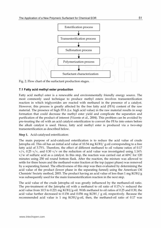
The purpose of this work was to develop new polymeric surfactants for enhanced oil recovery applications. Several experiments have been conducted to synthesize different surfactants based on fatty acid methyl ester derived from Jatropha oil. The experimental work started with the production of the methyl ester, followed by the synthesis of the surfactants and their characterizations. Figure 2 shows the experimental steps followed in this study.
www.intechopen.com
The Application of a New Polymeric Surfactant for Chemical EOR
51
Fig. 2. Flow chart of the surfactant production stages.
7.1 Fatty acid methyl ester production
Fatty acid methyl ester is a renewable and environmentally friendly energy source. The most commonly used technique to produce methyl esters involves transesterification reaction in which triglycerides are reacted with methanol in the presence of a catalyst. However, this process is greatly affected by the free fatty acid (FFA) content of the raw material. The presence of high FFA (i.e. high acid value) in the raw material results in soap formation that could decrease the methyl ester yield and complicate the separation and purification of the product of interest (Vicente et al., 2004). This problem can be avoided by pre-treating the oil with an acid catalyst esterification to convert the FFAs into esters before the alkali catalyst is used. Hence, fatty acid methyl ester is produced via a two-step transesterification as described below.
Step 1. Acid-catalysed esterification:
The main purpose of acid-catalyzed esterification is to reduce the acid value of crude Jatropha oil. This oil has an initial acid value of 10.54 mg KOH/ g-oil corresponding to a free fatty acid of 3.75%. Therefore, the effect of different methanol to oil volume ratios of 0.17 v/v, 0.25 v/v, and 0.30 v/v on the reduction of acid value was investigated using 1.14% v/w of sulfuric acid as a catalyst. In this step, the reaction was carried out at 60oC for 120 minutes using 250 ml round bottom flask. After the reaction, the mixture was allowed to settle for three hours and the methanol-water fraction at the top (upper phase) was removed by a separating funnel. The effectiveness of this step was then evaluated by determining the acid value of the product (lower phase in the separating funnel) using the American Oil Chemists' Society method, 2003. The product having an acid value of less than 1 mg KOH/g was subsequently used for the main transesterification reaction in the next step.
The acid value of the crude Jatropha oil was greatly influenced by the methanol-oil ratio. The pre-treatment of the Jatropha oil with a methanol to oil ratio of 0.17v/v reduced the acid value from 10.5 to 0.221 mg KOH/g-oil. With methanol to oil ratios of 0.25 and 0.30, the acid value further decreased to 0.156 and 0.056 mg KOH / g oil, respectively. Because the recommended acid value is 1 mg KOH/g-oil, then, the methanol-oil ratio of 0.17 was
Transesterification process
Esterification process
Sulfonation process
Polymerization process
Surfactant characterization
www.intechopen.com

Introduction to Enhanced Oil Recovery (EOR) Processes and Bioremediation of Oil-Contaminated Sites
52
selected as the optimum ratio for the acid-catalyzed esterification reaction at 60oC and 120 minutes of reaction time. Based on the weight of oil used in this step, the average product yield was about 90%, which is in agreement with the product yield obtained by Tiwari et al., (2007) who conducted the pre-treatment of Jatropha oil that contained 28 mg KOH/g-oil using a methanol-oil volume ratio of 0.28 over 88 minutes of reaction time.
Step 2. Alkaline-catalysed transesterification:
The transesterification reaction was conducted to produce methyl esters from the pre-treated Jatropha oil. Different methanol- oil ratios were evaluated at a constant ratio of potassium hydroxide (KOH) to oil ratio of 0.5%w/w. In this study, the volume ratios of methanol to oil volume were 0.16 v/v, 0.22 v/v, and 0.26 v/v. The reaction was carried out at 60oC for 35 minutes.
At the reaction time of 35 minutes, the yield of methyl ester obtained was similar for methanol to oil ratios of 0.22 and 0.26. For instance, a maximum yield of 99.8% and 99.3% were obtained for methanol to oil ratios of 0.22 and 0.26 respectively; while a yield of 96.4% was obtained when the lowest methanol to oil ratio of 0.16 was used. Therefore, the optimum methanol to oil ratio was chosen as 0.22. According to Tiwari et al. (2007) a maximum yield of 99% was obtained with a methanol to oil ratio of 0.16 v/v and 24 min of reaction time. As compared to other oils, a maximum yield of 95% was obtained from soybean oil with a methanol to oil molar ratio of 12:1 and 3 hours of reaction time (Xuejun et al., 2008). Therefore, Jatropha oil seems to be a promising source for methyl ester production.
Jatropha oil (wt %)
Soybean oil (wt %) (Sarin et al., 2007)
Palmitic acid methyl ester 17.24 11.0
Stearic acid methyl ester 9.79 4.0
Margaric acid methyl ester 0.11 -
Myristate methyl ester 0.09 0.1
Palmitoleic acid methyl ester 1.28 0.1
Linoleic acid methyl ester 35.21 53.2
Oleic acid methyl ester 36.28 23.4
Table 2. Analysis of the fatty acid methyl ester
The methyl ester produced at the optimum methanol to oil ratio was characterized by Gas Chromatography-Mass Spectrometry (GC-MS) to confirm the presence of fatty acid methyl esters. Table 2 summarizes the composition of the fatty acid methyl esters produced from Jatropha oil. The presence of methyl esters were assessed using the GC-MS library that is provided with the equipment. Table 2 indicates that the Jatropha oil methyl ester contains 27.23% of saturated fatty acid and 72.77% of unsaturated fatty acid. It was also found that the Jatropha oil has a high quantity of linoleic acid methyl ester (35.21 %) and oleic acid methyl ester (36.28%). If compared to soybean oil (Table 2), Jatropha oil has also great potential as a fatty acid source.
www.intechopen.com
The Application of a New Polymeric Surfactant for Chemical EOR
53
7.2 Surfactant synthesis
7.2.1 Sulfonation process
The fatty acid methyl ester produced from Jatropha oil was then sulfonated according to Chonlin et al., (1990). The purpose of the sulfonation process was to synthesize a sodium methyl ester sulfonate (SMES) based on fatty acid methyl esters as feedstocks. The sulfonation reaction was carried out at laboratory scale using a 250 ml round bottom flask. However, since n-butanol and sodium carbonate are already used in chemical EOR as cosolvent and alkali respectively, the SMES obtained was used in the polymerization reaction without any further purification so as to minimize the cost of surfactant manufacturing (Elraies et al., 2010).
7.2.2 Polymerization process
A single step route similar to Ye et al., (2004) was used to produce polymeric methyl ester sulfonate (PMES) via polymerization process. The principle of this process was to attach the sulfonate group of SMES to the polymer backbone (polyacrylamide) as a one component system for ITF reduction and viscosity control.
The polymerization process was performed using a 250 ml-three necked flask. In a typical run, the reaction was conducted using the methyl ester sulfonate (SMES) as the surfactant and potassium persulfate as the initiator. The initiator solution was prepared by dissolving 0.123 g of potassium persulfate in 10 ml of deionized water and then the pH of the solution was adjusted to 9-10 with sodium hydroxide. The surfactant solution was prepared by dissolving the appropriate amount of SMES in 100 ml deionized water. The appropriate amount of acrylamide monomer was dissolved in 70 ml of deionized water and purged with nitrogen to remove residual oxygen. Afterward, the surfactant solution was added to the acrylamide solution and stirred under a nitrogen atmosphere until a clear solution was observed. This mixture was then heated to 60oC and the initiator was added. The polymerization reaction was conducted at 60oC for 1.5 hours using and auto shaker water bath. The crude product was then extracted with acetone and dried in an oven for 12 hours (Elraies et al., 2011).
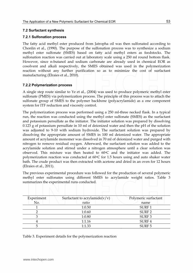
The previous experimental procedure was followed for the production of several polymeric methyl ester sulfonates using different SMES to acrylamide weight ratios. Table 3 summarizes the experimental runs conducted.
Experiment No.
Surfactant to acrylamide(v/v) ratio
Polymeric surfactant name
1 1:0.50 SURF 1
2 1:0.60 SURF 2
3 1:0.80 SURF 3
4 1:1.16 SURF 4
5 1:1.33 SURF 5
Table 3. Experiment details for the polymerization reaction
www.intechopen.com

Introduction to Enhanced Oil Recovery (EOR) Processes and Bioremediation of Oil-Contaminated Sites
54
7.3 Surfactant characterization
7.3.1 FTIR spectroscopy analyses
A FTIR spectrophotometer was used to determine the chemical functional groups present in the surfactant. Different functional groups are susceptible to absorb characteristic frequencies of IR radiation. Figure 3 shows the FTIR spectrum of sodium methyl ester sulfonate. All the IR absorption bands are analyzed with reference to the Spectrometric identification of organic compounds by Silverstein et al., (2005). The broad absorbance peaks between 3300-2500 cm-1 represent the O–H stretching of carboxylic acid. The presence of esters is indicated by the absorbance peak of C=O stretching vibration between 1730-1715 cm-1. The presence of the significant peak at 1450 cm-1 corresponds to the asymmetrical bending vibration band of methyl group (C-H). Peaks between 1160 - 1120 cm-1 indicate the presence of sulfonate groups due to S=O stretching (Silverstein et al., 2005; Awang & Goh, 2008). The peaks at 1410 and 1068 cm-1 are another indication of the presence of sulfonate groups due to the S=O stretching vibration. These results indicate that this compound must be sodium methyl ester sulfonate.
The polymeric surfactants produced based on sodium methyl ester sulfonate were also characterized by FTIR. The IR spectrums recorded of the five produced surfactants showed similar pattern but the percentage of transmission is different due to the variation in their molecular weights. The IR spectrums indicate that the chemical structures for these five surfactants are the same. Figure 4 presents the FTIR spectrum for surfactant SURF 1. Figure 5 shows the IR spectra of the other four surfactants (SURF 2, SURF 3, SURF 4, and SURF 5).
Fig. 3. FTIR spectrum of sodium methyl ester sulfonate
In Figure 4, the peaks between 1160 - 1120 cm-1 and 1409 and 1068 cm-1 indicate the presence of sulfonate groups due to C=O stretching. The absorbance peaks between 1730-1715 cm-1 represent the S=O stretching vibration indicating the presence of esters. The presence of the
0
10
20
30
40
50
60
70
80
40080012001600200024002800320036004000
Tra
nsm
itta
nce (
%)
Wave number, cm-1
2495
11
37
.9
1122.4
9
1411.8
0
87
9.4
8
1722.3
9 61
9.1
1
3375.2
0
2979.8
2
www.intechopen.com

The Application of a New Polymeric Surfactant for Chemical EOR
55
significant peak at 1450 cm-1 corresponds to the asymmetrical bending vibration band of methyl group (C-H). Changes in the absorbance peaks from 2975 to 3352 cm-1 are due to the introduction of acrylamide to the surfactant. The tiny peaks from 3350 to 3180 cm-1 are an indication of the presence of primary and secondary amides due to N-H stretching. The peaks between 1680 and 1630 cm-1 are another indication of the presence of amide groups due to the C=O stretching vibration (Silverstein et al., 2005).
Fig. 4. FTIR spectrum of polymeric SURF 1
Fig. 5. FTIR spectrum of polymeric surfactants (SURF 2 to SURF 5)
0
5
10
15
20
25
30
35
40
45
40080012001600200024002800320036004000
Tra
nsm
itta
nce (
%)
Wave number (cm-1)
14
51
.8
1409.8
7
1157.2
1
1120.5
61068.4
9
86
5.9
8
61
9.1
1
1633.9
5
1730.2
1
2115.7
7
2470.6
4
3191.9
7
3352.0
5
3575.0
6
0
5
10
15
20
25
30
35
40
45
50
40080012001600200024002800320036004000
Tra
nsm
itta
nce (
%)
Wave number, cm-1
SURF 2
SURF 5
SURF 4
SURF 3
www.intechopen.com
Introduction to Enhanced Oil Recovery (EOR) Processes and Bioremediation of Oil-Contaminated Sites
56
7.3.2 Thermal stability analyses
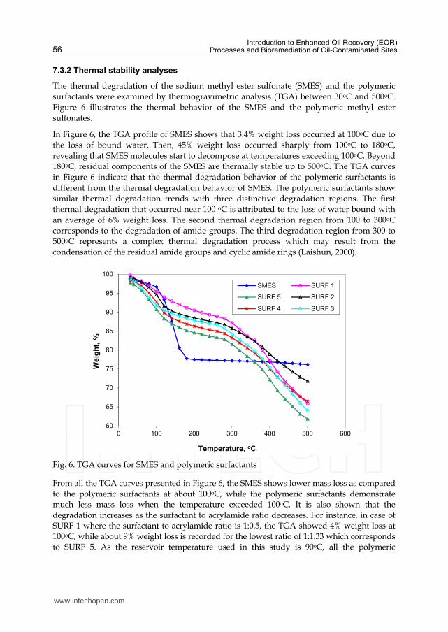
The thermal degradation of the sodium methyl ester sulfonate (SMES) and the polymeric surfactants were examined by thermogravimetric analysis (TGA) between 30oC and 500oC. Figure 6 illustrates the thermal behavior of the SMES and the polymeric methyl ester sulfonates.
In Figure 6, the TGA profile of SMES shows that 3.4% weight loss occurred at 100oC due to the loss of bound water. Then, 45% weight loss occurred sharply from 100oC to 180oC, revealing that SMES molecules start to decompose at temperatures exceeding 100oC. Beyond 180oC, residual components of the SMES are thermally stable up to 500oC. The TGA curves in Figure 6 indicate that the thermal degradation behavior of the polymeric surfactants is different from the thermal degradation behavior of SMES. The polymeric surfactants show similar thermal degradation trends with three distinctive degradation regions. The first thermal degradation that occurred near 100 oC is attributed to the loss of water bound with an average of 6% weight loss. The second thermal degradation region from 100 to 300oC corresponds to the degradation of amide groups. The third degradation region from 300 to 500oC represents a complex thermal degradation process which may result from the condensation of the residual amide groups and cyclic amide rings (Laishun, 2000).
Fig. 6. TGA curves for SMES and polymeric surfactants
From all the TGA curves presented in Figure 6, the SMES shows lower mass loss as compared to the polymeric surfactants at about 100oC, while the polymeric surfactants demonstrate much less mass loss when the temperature exceeded 100oC. It is also shown that the degradation increases as the surfactant to acrylamide ratio decreases. For instance, in case of SURF 1 where the surfactant to acrylamide ratio is 1:0.5, the TGA showed 4% weight loss at 100oC, while about 9% weight loss is recorded for the lowest ratio of 1:1.33 which corresponds to SURF 5. As the reservoir temperature used in this study is 90oC, all the polymeric
60
65
70
75
80
85
90
95
100
0 100 200 300 400 500 600
We
igh
t, %
Temperature, oC
SMES SURF 1
SURF 5 SURF 2
SURF 4 SURF 3
www.intechopen.com

The Application of a New Polymeric Surfactant for Chemical EOR
57
surfactants retain an average of 95% of their original structure and mass. It could be concluded that these polymeric surfactants are thermally stable under the desired reservoir temperature.
7.3.3 Interfacial tension measurements
Interfacial tension (IFT) measurements between crude oil and aqueous solutions of sodium methyl ester sulfonate (SMES) and polymeric methyl ester sulfonates were performed at several surfactant concentrations. All the measurements were conducted at 29oC using the spinning drop method. Angsi I-68 crude oil (Malaysia) was used throughout this study. The total acid number was 0.478 mg KOH/g. The API gravity was 40.1o and live oil viscosity was 0.3 cP at reservoir temperature.
Figure 7 shows the interfacial tension as a function of SMES concentration and time. At 0.2wt% loading, SMES reduces the interfacial tension between softened water and crude oil from about 13.6 mN/m to 0.82 mN/m. This demonstrates the surface adsorption and aggregative properties of the new surface-active compound. The interfacial tension of the system crude oil-SMES solution reduces drastically as surfactant concentration increases. For instance, when the surfactant concentration is increased from 0.2 wt% to 0.4 wt% and 0.6 wt%, the IFT drops continuously to values of 0.56 mN/m and 0.45 mN/m respectively.
The surface activity of the SMES was also compared with the surface activity of a commercial surfactant (sodium dodecyl sulphate, SDS). Figure 7 shows that at a concentration of 0.2wt%, the SMES and SDS reduced the interfacial tension of the system crude oil-aqueous solution to 0.82 mN/m and 0.63 mN/m respectively. While, at a concentration of 0.4 wt%, the reduction of IFT in the system crude oil-aqueous solution is similar to the IFT value obtained with 0.2wt% of sodium dodecyl sulphate (SDS). These results indicate that there is no much difference in the interfacial tension reduction provided by the SMES compared to SDS, especially considering the fact that the manufacture cost of the SMES is lower than the cost of the commercial SDS.
Fig. 7. IFT for the system crude oil- aqueous solution as a function of surfactant concentration and measuring time.
0
0.1
0.2
0.3
0.4
0.5
0.6
0.7
0.8
0.9
0 5 10 15 20 25 30 35
Inte
rfacia
l te
nsio
n,
mN
/m
Time, minute
SMES 0.2% SDS 0.2% SMES 0.4%
SMES 0.6% SMES 0.8%
www.intechopen.com

Introduction to Enhanced Oil Recovery (EOR) Processes and Bioremediation of Oil-Contaminated Sites
58
Figure 8 presents the IFT performance of polymeric methyl ester sulfonates (PMES) as a function of surfactant (SMES) to polymer (acrylamide) ratio and measuring time. The PMES showed a significant reduction of the IFT of the system crude oil-aqueous solution; IFT decreases as the surfactant to acrylamide ratio increases. As shown in Figure 8, the interfacial tensions between crude oil and surfactant solution reduces from 13.6 mN/m to 0.461 mN/m at a surfactant:acrylamide ratio of 1:0.8 (1.25 surfactant/acrylamide) , and the IFT of the system reaches 0.296 mN/m at a surfactant:acrylamide ratio of 1:0.4 (2.5 surfactant/acrylamide ratio). This demonstrates the aggregative properties of the attached sulfonated group to the polymer chains. As the surfactant to acrylamide ratio increases, the more surfactant is being attached to the polymer backbone and thereby lower IFT values are reached.
Fig. 8. IFT of the system crude oil – aqueous solution as a function of surfactant to acrylamide ratios and measurement time.
7.3.4 Viscosity measurements
The kinematic viscosity of the polymeric surfactants was measured using a Tamson viscometer. All the measurements were performed at a reservoir temperature of 90oC. In the polymeric surfactant mixtures, surfactant concentration was fixed at 0.2wt%, while the concentration of acrylamide was changed. The purpose of this test was to screen the polymeric surfactant based on performance for the subsequent core flood tests.
The effect of each surfactant to acrylamide ratio on the viscosity performance is illustrated in Figure 9. The viscosity of the polymeric surfactant significantly increases as the surfactant to acrylamide ratio decreases. This is due to the increasing amount of polymer chains attached to the surfactant. The viscosity of the polymeric surfactant having a surfactant:acrylamide ratio of 1:0.4 (2.5 surfactant/acrylamide) is lower than the viscosity of the crude oil (1.654 mm/sec) and therefore this polymeric surfactant (SURF 1) was not selected.
0.1
0.2
0.3
0.4
0.5
0 1 2 3 4 5
Inte
rfacia
l te
nsio
n,
mN
/m
Time, minute
1:0.4 1:0.5 1:0.6 1:0.8
www.intechopen.com

The Application of a New Polymeric Surfactant for Chemical EOR
59
Fig. 9. Viscosity as a function of different surfactant to acrylamide ratios.
The selection of the optimum surfactant:acrylamide ratio was based on several factors including production cost, IFT, and viscosity. Therefore, the polymeric surfactant having a surfactant/acrylamide ratio of 1:0.5 was chosen as the optimum ratio. Then, the viscosity of the chemical slug can be adjusted by increasing the polymeric surfactant concentration to yield a suitable viscosity and an ultra low IFT. Unlike the surfactant:acrylamide ratios of 1:0.6 and 1:0.8, the viscosity of these solutions were very high compared to the viscosity of the crude oil. If the concentration of these polymeric surfactants is increased in aqueous solutions to render low values of IFT, then the high viscosities of the polymeric surfactant solutions will cause injectivity problems during the injection of the chemical slug into the porous media. Therefore, the polymeric surfactant with a surfactant:acrylamide ratio of 1:05 was selected as the optimum PMES for IFT reduction and viscosity control. Similarly, this PMES allows achieving an effective chemical slug that is able to propagate into the rock formation upon injection without losing its integrity.
7.3.5 Viscosity and IFT performance for the optimum polymeric surfactant
The viscosity and IFT performances of the optimum polymeric surfactant were investigated using different concentrations of PMES. Figure 10 shows that the viscosity of the solution significantly increases as PMES concentration increases. The viscosity of the solution was approximately 1.75 mm/sec for a 0.2wt% PMES solution concentration, 2.533 mm/sec for 0.4wt% concentration, and 5.124 mm/sec with the highest PMES solution concentration (0.7wt%). The latter solution viscosity is very high as compared to the viscosity of the crude oil (1.654 mm/sec). So in order to design a cost-effective polymeric surfactant slug that offers a favourable mobility ratio, a polymeric surfactant concentration of 0.4wt% was chosen as the optimum concentration for the chemical flooding displacement of the crude oil used in this work.
0
0.5
1
1.5
2
2.5
3
3.5
1:0.4. 1:0.5. 1:0.6. 1:0.8. crude oil
Viscosity, m
m/sec2
Surfactant to acrylamide ratio
www.intechopen.com

Introduction to Enhanced Oil Recovery (EOR) Processes and Bioremediation of Oil-Contaminated Sites
60
Figure 10 also shows the interfacial tension as a function of different PMES concentrations. PMES shows excellent results in terms of IFT reduction. IFT between the crude oil and surfactant solution is reduced from 13.6 mN/m to 0.323 mN/m using 0.2wt% of PMES concentration. And the IFT reduces drastically as the concentration of polymeric surfactant increases. At the optimum PMES concentration of 0.4%, the IFT decreases to 0.192 mN/m.
Fig. 10. IFT and viscosity as a function of different polymeric surfactant concentration
7.3.6 Effect of alkali on the PMES viscosity and IFT performance
Since alkali has a significant impact on ASP flooding performance, the effect of alkali on the performance of the PMES was investigated using different sodium carbonate concentrations at a fixed concentration of polymeric surfactant (0.4wt%) in the aqueous solution. The purpose of these measurements was not only to study the effect of the alkali on the IFT reduction, but also to determine if the presence of sodium carbonate in the system would affect the viscosity of the polymeric surfactant.
Figure 11 shows the viscosity performance in the absence and presence of sodium carbonate at 90oC. The presence of alkali at concentrations ranging from 0.2wt% to 1wt% does not affect the viscosity of the system; the viscosity of the polymeric surfactant remains constant at 2.533 mm2/sec. This shows the stability of the viscosity of the new polymeric surfactant in the presence of sodium carbonate if compared to the conventional ASP formula where its viscosity is greatly affected by the added alkali (Nasr-El-Din et al., 1992).
0
0.05
0.1
0.15
0.2
0.25
0.3
0.35
0
1
2
3
4
5
6
0.1 0.2 0.3 0.4 0.5 0.6 0.7 0.8
IFT
, m
N/m
Vis
co
sit
y,
mm
2/s
ec
Surfactant concentration, wt%
Viscosity
IFT
www.intechopen.com

The Application of a New Polymeric Surfactant for Chemical EOR
61
Fig. 11. Viscosity and IFT performance of PMES solution as a function of different Na2CO3
concentrations.
Figure 11 shows the effect of alkali concentrations on the IFT performance of the polymeric surfactant. The IFT decreases significantly with the increase of alkali concentration until it levels off (0.024 mN/m) when the concentration of Na2CO3 reaches 0.8wt%. At an alkali concentration of 0.2wt%, the IFT of the system slightly decreases. However, significant IFT redaction is observed when the alkali concentration increases from 0.2wt%to 0.8wt%. This rapid decrease in the IFT value can be explained by the production of in-situ surfactants due to saponification reactions between the alkali and the acidic groups in the crude oil. These natural surfactants are associated with the polymeric surfactant to produce synergistic mixtures adsorbed at the oil/brine interface. As a result, a concentration of 0.8wt% of sodium carbonate was selected as the optimum alkali concentration in the presence of 0.4wt% of polymeric surfactant concentration.
7.3.7 Static surfactant adsorption
Surfactant adsorption is detrimental as it results in surfactant loss and reduces surfactant activity. The adsorption of surfactant from aqueous solution to sandstone surface was investigated in the absence and presence of different alkali concentrations. The sandstone was collected from Lumut Beach, Malaysia. The adsorption of surfactant for each case was determined by comparing the obtained refractive index before and after equilibrium (Elraies et al., 2011).
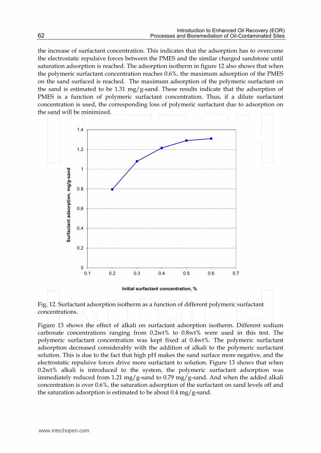
Figure 12 presents the adsorption isotherm as a function of polymeric surfactant concentration. Surfactant adsorption increased as the surfactant concentration increased. At low surfactant concentration, surfactant adsorption occurs mainly due to ion exchange. As surfactant concentration exceeds 0.4wt%, the adsorption increment progressed slowly with
0
0.05
0.1
0.15
0.2
0.25
0
0.5
1
1.5
2
2.5
3
0 0.2 0.4 0.6 0.8 1 1.2 1.4
IFT
, m
N/m
Vic
osit
y,
mm
2/s
ec
Alkali concentration, %
Viscosity
IFT
www.intechopen.com
Introduction to Enhanced Oil Recovery (EOR) Processes and Bioremediation of Oil-Contaminated Sites
62
the increase of surfactant concentration. This indicates that the adsorption has to overcome the electrostatic repulsive forces between the PMES and the similar charged sandstone until saturation adsorption is reached. The adsorption isotherm in figure 12 also shows that when the polymeric surfactant concentration reaches 0.6%, the maximum adsorption of the PMES on the sand surfaced is reached. The maximum adsorption of the polymeric surfactant on the sand is estimated to be 1.31 mg/g-sand. These results indicate that the adsorption of PMES is a function of polymeric surfactant concentration. Thus, if a dilute surfactant concentration is used, the corresponding loss of polymeric surfactant due to adsorption on the sand will be minimized.
Fig. 12. Surfactant adsorption isotherm as a function of different polymeric surfactant concentrations.
Figure 13 shows the effect of alkali on surfactant adsorption isotherm. Different sodium carbonate concentrations ranging from 0.2wt% to 0.8wt% were used in this test. The polymeric surfactant concentration was kept fixed at 0.4wt%. The polymeric surfactant adsorption decreased considerably with the addition of alkali to the polymeric surfactant solution. This is due to the fact that high pH makes the sand surface more negative, and the electrostatic repulsive forces drive more surfactant to solution. Figure 13 shows that when 0.2wt% alkali is introduced to the system, the polymeric surfactant adsorption was immediately reduced from 1.21 mg/g-sand to 0.79 mg/g-sand. And when the added alkali concentration is over 0.6%, the saturation adsorption of the surfactant on sand levels off and the saturation adsorption is estimated to be about 0.4 mg/g-sand.
0
0.2
0.4
0.6
0.8
1
1.2
1.4
0.1 0.2 0.3 0.4 0.5 0.6 0.7
Su
rfacta
nt
ad
so
rpti
on
, m
g/g
-san
d
Initial surfactant concentration, %
www.intechopen.com

The Application of a New Polymeric Surfactant for Chemical EOR
63
Fig. 13. The effect of alkali concentration on the polymeric surfactant adsorption isotherm
7.3.8 Coreflood test
Although the proposed Alkali/Polymeric/Surfactant (APS) formulation has shown promising potential in these preliminary screening tests, this is a relatively new technology for chemical EOR that requires more research. In order to design a cost-effective injection strategy to recover residual oil, core flood testing at reservoir conditions is essential. In this study, five core flood tests were performed to determine the effects of chemical concentration and slug size on oil recovery performance. For all coreflood experiments, the fluid injection sequence was as follows first waterflooding: followed by the injection of 0.5 PV of chemical slug, and finally waterflooding was resumed. Consolidated Brea Sandstone cores were used for evaluating the proposed procedure. Table 4 summarizes the physical core properties and coreflood results.
Property Run 1 Run 2 Run 3 Run 4 Run 5
Length, cm 7.6 7.5 7.5 7.5 7.5
Diameter, cm 3.8 3.8 3.8 3.8 3.8
Permeability, md 88.4 113 84.9 82 94
Porosity, % 15.7 16.4 16.9 16.5 16.4
Pore volume, cc 13.3 13.2 14.5 13.9 13.2
Surfactant concentration, % 0.4 0.6 1 0.6 0.6
Alkali concentration, % 0.8 0.8 0.8 0.2 1
Waterflood recovery (% OOIP) 48.1 53.7 56.2 50.0 54.2
APS recovery (% OOIP) 12.6 16.2 20.7 12.8 9.0
Total recovery (% OOIP) 60.7 70.0 77.0 62.8 63.2
Table 4. Summary of core samples properties and coreflood tests
0
0.2
0.4
0.6
0.8
1
1.2
1.4
0 0.2 0.4 0.6 0.8 1
Su
rfacta
nt
ad
so
rpti
on
, m
g/g
-san
d
Alkali concentration, %
www.intechopen.com

Introduction to Enhanced Oil Recovery (EOR) Processes and Bioremediation of Oil-Contaminated Sites
64
Effect of Surfactant Concentration
Preliminary testing indicated that the optimum formulation for the alkali-polymeric surfactant system was obtained for a composition of 0.8wt% alkali (Na2CO3) and 0.4wt% of polymeric surfactant. However, in order to examine the effectiveness of the new polymeric surfactant for enhanced oil recovery application, three additional concentrations of the polymeric surfactant (0.4%, 0.6%, 1%) were evaluated to confirm the optimum formulation of the new APS system. For all coreflood runs # 1, #2, and # 3 the alkali (sodium carbonate) concentration was kept constant at 0.8wt%, while for coreflood runs # 4 and # 5 Na2CO3 concentration was 0.2 wt% and 1wt% respectively.
Figure 14 shows the recovery performance as a function of pore volume injected for coreflood tests # 1, # 2, and # 3. Figure 14 shows that Run # 3 with the highest polymeric surfactant concentration (1wt%) had accomplished a better performance in recovering oil than Run # 2 with a polymeric surfactant concentration of 0.6wt% and Run # 1 with a polymeric surfactant concentration of 0.4wt%. After the injection of only 0.5 PV of APS, the percentage of oil recovery for Run # 2 and Run# 3 was 16.2% and 20.7% of the OOIP respectively. While, in Run # 1, with the lowest polymeric surfactant concentration, oil recovery was only 12.6 % of the OOIP after the injection of 0.5 PV of APS slug followed by extended waterflooding. Based on the IFT measurements, the high oil recovery from Run # 2 and Run # 3 was due to the synergistic action of the polymeric surfactant and the alkali causing the emulsification and mobilization of the crude oil. However, in Run # 1 with 0.4% of polymeric surfactant concentration, the recovery mechanism is only due to the formed microemulsion as a result of the low IFT observed during IFT test. In addition to the low surfactant concentration, the viscosity of the polymeric surfactant slug might not be high enough to efficiently displace emulsified crude oil. Based on these results, a chemical slug having a concentration of 0.6wt% of the polymeric surfactant was selected as the optimum APS formulation.
Fig. 14. Effect of surfactant concentration on oil recovery performance
www.intechopen.com
The Application of a New Polymeric Surfactant for Chemical EOR
65
Effect of Alkali Concentration
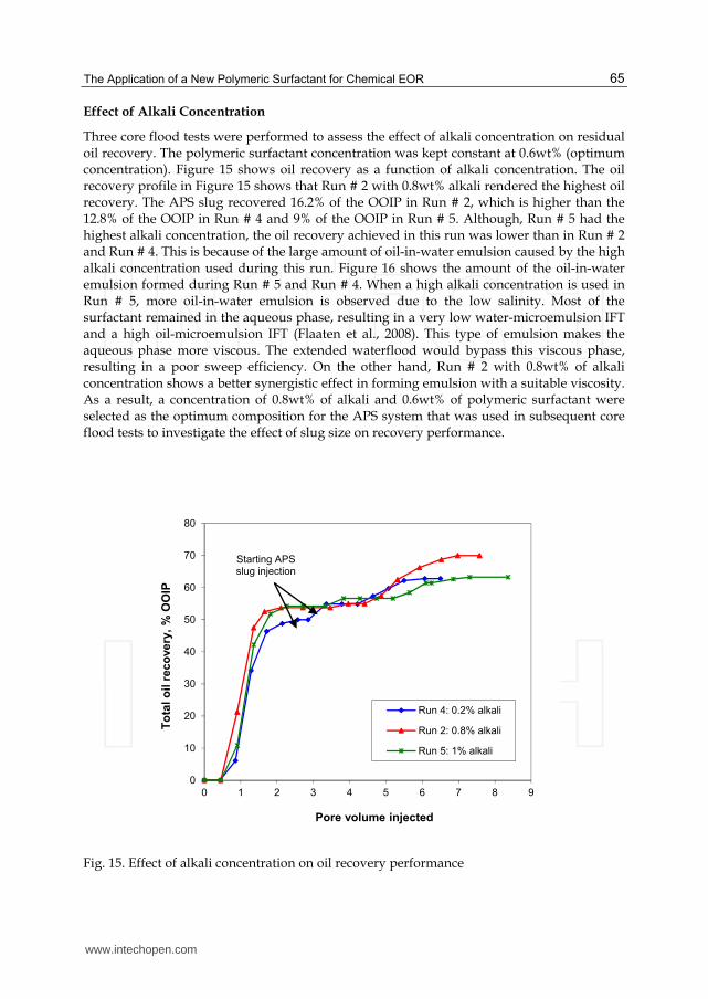
Three core flood tests were performed to assess the effect of alkali concentration on residual oil recovery. The polymeric surfactant concentration was kept constant at 0.6wt% (optimum concentration). Figure 15 shows oil recovery as a function of alkali concentration. The oil recovery profile in Figure 15 shows that Run # 2 with 0.8wt% alkali rendered the highest oil recovery. The APS slug recovered 16.2% of the OOIP in Run # 2, which is higher than the 12.8% of the OOIP in Run # 4 and 9% of the OOIP in Run # 5. Although, Run # 5 had the highest alkali concentration, the oil recovery achieved in this run was lower than in Run # 2 and Run # 4. This is because of the large amount of oil-in-water emulsion caused by the high alkali concentration used during this run. Figure 16 shows the amount of the oil-in-water emulsion formed during Run # 5 and Run # 4. When a high alkali concentration is used in Run # 5, more oil-in-water emulsion is observed due to the low salinity. Most of the surfactant remained in the aqueous phase, resulting in a very low water-microemulsion IFT and a high oil-microemulsion IFT (Flaaten et al., 2008). This type of emulsion makes the aqueous phase more viscous. The extended waterflood would bypass this viscous phase, resulting in a poor sweep efficiency. On the other hand, Run # 2 with 0.8wt% of alkali concentration shows a better synergistic effect in forming emulsion with a suitable viscosity. As a result, a concentration of 0.8wt% of alkali and 0.6wt% of polymeric surfactant were selected as the optimum composition for the APS system that was used in subsequent core flood tests to investigate the effect of slug size on recovery performance.
Fig. 15. Effect of alkali concentration on oil recovery performance
0
10
20
30
40
50
60
70
80
0 1 2 3 4 5 6 7 8 9
To
tal
oil r
eco
ve
ry,
% O
OIP
Pore volume injected
Run 4: 0.2% alkali
Run 2: 0.8% alkali
Run 5: 1% alkali
Starting APS slug injection
www.intechopen.com

Introduction to Enhanced Oil Recovery (EOR) Processes and Bioremediation of Oil-Contaminated Sites
66
Fig. 16. Oil-in-water emulsion formed during Run # 4 and Run # 5 (A & B show the produced oil and water during waterflooding and after APS slug injection respectively)
Effect of slug size
Determining the most effective chemical slug size which renders the minimum chemical consumption and maximizes oil recovery is one of the most important criterions in the optimization process. To investigate the effect of slug size, the optimum APS formulation was used. In this experimental phase the effect of three different chemical slug sizes on oil recovery were evaluated.
Fig. 17. Effect of slug size on oil recovery performance
Figure 17 shows the oil recovery performance as a function of APS slug size. The APS slug size was varied from 0.3 PV in Run # 6, 0.5 PV in Run # 2, and 1 PV in Run # 7. Figure 17 shows that the recovery performance is much improved as the APS slug size was increased
0
10
20
30
40
50
60
70
80
0 2 4 6 8 10 12
To
tal
oil r
eco
ve
ry,
% O
OIP
Pore volume injected
Run 6: 0.3 PV
Run 2: 0.5 PV
Run 7: 1 PV
Starting APS slug injection
A B
AB
Run # 4 (0.2% alkali) Run # 5 (1% alkali)
www.intechopen.com

The Application of a New Polymeric Surfactant for Chemical EOR
67
from 0.3 PV to 0.5 PV. However, only small increment recovery (0.9%) was observed when the APS slug size was increased from 0.5 PV in Run # 2 to 1 PV in Run # 7. This indicates that the injection of 0.5 PV of APS slug is effective and therefore more economical than the other relatively larger slug size. .
8. Conclusion
Based on the findings and results illustrated in this study, it can be concluded that the non-edible Jatropha oil has great potential as raw material for the production of surfactants. Production of sodium methyl ester sulfonate (SMES) based on Jatropha oil can satisfy EOR requirements, because it is an inexpensive, natural, and renewable raw material. SMES provides appropriate surfactant properties at low cost, and therefore it offers a strong economic incentive to substitute SDS and other commercial surfactants for EOR applications.
On the basis of the results obtained from IFT and viscosity measurements, the polymeric methyl ester sulfonate (PMES) shows excellent properties for IFT reduction and viscosity control. The grafting of SMES onto acrylamide polymers to produce PMESs offers many benefits as compared to the existing chemical EOR methods. The presence of both the surfactant and polymer in one component system makes the PMES easier to handle especially in offshore applications.
The major contribution of this new APS combination is its ability to maintain the desired viscosity in the presence of sodium carbonate. The optimum alkali-polymeric formulation in terms of oil recovery performance obtained from the coreflood tests corresponds to a concentration of sodium carbonate of 0.8wt% and 0.6wt% of polymeric surfactant. The injection of 0.5 PV of APS slug rendered an oil recovery of 16.2% of the OOIP. These experimental results show the potential of the new alkali-polymeric surfactant system as a promising chemical flooding formulation if compared to the conventional ASP flooding formulation.
9. References
Abdala, A. A. (2002). Solution Rheology & Microstructure of Associative Polymers, Ph.D. thesis, North Carolina State University, Raleigh.
American Oil Chemists' Society (2003). Sampling and analysis of commercial fats and oils. Cd 3d-63,
Awang, M. & Goh, M. S. (2008). Sulfonation of phenols extracted from the pyrolysis oil of oil palm shells for enhanced oil recovery, ChemSusChem, Vol. 1, pp. 210-214.
Austad, T. & Milter, J. (2000). Surfactant Flooding in Enhanced Oil Recovery. Surfactants, In: Fundamentals and Applications in the Petroleum Industry. UK: Cambridge University Press, pp. 203-250.
Berger, P.D. & Lee, C.H. (2006). Improved ASP process using organic alkali, the SPE/DOE symposium on improved oil recovery, SPE 99581, Tulsa, April, 2006.
Bosswell, M.J. (2003). Plant Oils: Wealth, health, energy and environment. Proc. International Conference of Renewable Energy Technology for rural Development, Kathmandu, Nepal, June, 2003.
www.intechopen.com

Introduction to Enhanced Oil Recovery (EOR) Processes and Bioremediation of Oil-Contaminated Sites
68
Clara, H., Larry, J.C., Lorenzo, A., Abel, B., Jie, Q., Phillip, C.D., &, Malcolm, J.P. (2001). ASP system design for an offshore application in the La Salina field, Lake Maracaibo, SPE Latin American and Caribbean petroleum engineering conference, SPE 69544 Buenos Aires, March, 2001.
Chonlin, L., Orear, E. A., Harwell, J.H., & Sheffield, J.A. (1990). Synthesis and characterization of a simple chiral surfactant sodium S-(-)-β-citronellyl sulfate, Journal of colloid and interface science, Vol. 137, pp. 296-299.
Craft, B.C., Hawkins, M., & Terry, R.E. (1991). Applied Petroleum Reservoir Engineering. Second Edition, Englewood, Cliffs NJ: Prentice Hall PTR. 4-6, pp. 376-384.
De Groot, M. (1929). Flooding process for recovering oil from subterranean oil-bearing strata, U. S. Patent 1 823 439.
Elraies, K. A., Tan, I., Awang, M., & Saaid, I. (2010a). Synthesis and Performance of Sodium Methyl Ester Sulfonate for Enhanced Oil Recovery. Petroleum Science and Technology, Vol. 28, No. 17, pp. 1799 – 1806.
Elraies, K. A., & Tan, I. (2010a). Design and Application of a New Acid-Alkali-Surfactant Flooding Formulation for Malaysian reservoirs, the SPE Asia Pacific Oil & Gas Conference and Exhibition, SPE 133005, Brisbane, October, 2010.
Elraies, K. A., Tan, I., Fathaddin, M., and Abo-Jabal, A. (2011). Development of a New Polymeric Surfactant for Chemical Enhanced Oil Recovery, Petroleum Science and Technology, Vol. 29, No. 14, pp. 1521 – 1528.
Energy Information Administration (2003). U.S. Crude Oil, Natural Gas, and Natural Gas Liquids Reserves, (2002) Annual Report. Office of Oil and Gas, U.S. Department of Energy. Washington. 20.
Falls, A.H., Thigpen, D.R., Nelson, R.C., Ciaston, J.W., Lawson, J.B., Good, P.A., & Shahin, G.T. (1992). A Filed Test of Cosurfactant-Enhanced Alkaline Flooding, the 8th Symposium on Enhanced Oil Recovery, SPE/DOE 24117, Tulsa, April, 1992.
Flaaten, A.K., Nguyen, Q.P., Pope, G.A., & Zhang, J. (2008). A systematic laboratory approach to low-cost, high-performance chemical flooding, the improved oil recovery symposium, SPE/DOE 113469, Tulsa, April, 2008.
Green, D.W., & Willhite, G.P. (1998). Enhanced Oil Recovery. Richardson Taxis: Society of Petroleum Engineers, SPE Textbook Series, 6, pp. 1-7,
Gregorio, C.G. (2005). Fatty Acids and Derivatives from Coconut Oil, Bailey’s Industrial Oil and Fat Products, Sixth Edition, Six Volume Set,.
Hou., et al. (2001). Study of the Effect of ASP Solution Viscosity on Displacement Efficiency, the 2001 SPE annual technical conference and exhibition, SPE 71492, New Orleans, LA, September, 2001.
Laishun, S. (2000). An approach to the flam retardation and smoke suppression of ethylene-vinyl acetate copolymer by plasma grafting of Acrylamide, Reactive and Functional Polymers, Vol. 45, pp. 85-93.
Li, G., Mu, J., Li, Y., & Yuan, S. (2000). An experimental study on alkaline/surfactant/polymer flooding systems using nature mixed carboxylate, Colloids and Surfaces A: Physicochemical and Engineering Aspects, Vol. 173, pp. 219-229.
Liu, S. 2008.Alkaline Surfactant Polymer Enhanced Oil Recovery Process, Ph.D. thesis, Rice University, Houston, Texas.
www.intechopen.com
The Application of a New Polymeric Surfactant for Chemical EOR
69
Mayer, E.H., Berg, R.L., Carrnichale, J.D., & Weinbrandt, R.M. (1983). Alkaline injection for enhanced oil recovery - a status report, the joint SPE/DOE enhanced oil recovery symposium, SPE 8848, Tulsa, April, 1983.
McCafferty, J.F., & McClaflin, G.G. (1992). The Field Application of a Surfactant for the Production of Heavy, Viscous Crude Oils, the 67th Annual Technical Conference and Exhibition, SPE 24850, Washington, DC, October, 1992.
Mohan, K. (2009). Alkaline Surfactant Flooding for Tight Carbonate Reservoirs, the Annual Technical Conference and Exhibition, SPE 129516, New Orleans, October, 2009.
Nasr-El-Din, H.A., Hawkins, B.F., & Green, K.A. (1992). Recovery of Residual Oil Using the Alkaline/Surfactant/Polymer Process: Effect of Alkali Concentration, Journal of Petroleum Science and Engineering, Vol. 6, pp. 381-388.
Nelson, R.C., Lawson, J.B., Thigpen, D.R., & Stegemeier, G.L. (1984). Cosurfactant-enhanced alkaline flooding, SPE 12672, enhanced oil recovery symposium, Tulsa, April, 1984.
Pant, K.S., Kumar, D. & Gairola, S. (2006). Seed oil content variation in Jatropha curcas L. in different altitudinal ranges and site conditions in H.P, India. Lyonia, Vol. 11, pp. 31-34.
Pingping, S., Jialu, W., Shiyi, Y., Taixian, Z., & Xu, J. (2009). Study of Enhanced-Oil-Recovery Mechanism of Alkali/Surfactant/Polymer Flooding in Porous Media from Experiments, SPE Journal, Vol. 14, No. 2, pp. 237-244.
Pitts, M.J., Dowling, P., Wyatt, K., Surkalo, H. & Adams, C. (2006). Alkaline-Surfactant-Polymer Flood of the Tanner Field, SPE 100004, the Symposium on Improved Oil Recovery, Tulsa, April, 2006.
Pramanik, K. (2003). Properties and use of Jatropha curcas oil and diesel fuel blends in compression ignition engine, Renewable Energy, Vol. 28, pp. 239–248.
Pratap, M., & Gauma M.S. (2004). Field Implementation of Alkaline-Surfactant-Polymer (ASP) Flooding: A maiden effort in India, SPE 88455, the Asia Pacific Oil and Gas Conference and Exhibition, Perth, October, 2004.
Reisberg, J., & Doscher, T.M. (1956). Interfacial phenomena in crude-oil-water systems, Production Monthly, pp. 43-50.
Rudin, J., & Wasan, D.T. (1992). Mechanisms for Lowering of Interfacial Tension in Alkali/Acidic Oil Systems: Effect of Added Surfactant, Industrial & Engineering Chemistry Research, Vol. 31, pp. 1899-1906.
Sarin, R., Sharma, M., Sinharay, S., & Malhotra, R.K. (2007). Jatropha-Palm biodiesel blends: An optimum mix for Asia, Fuel, Vol. 86, pp. 1365-1371.
Silverstein, R. M., Webster F. X., & Kiemle, D. J. (2005). Spectrometric identification of organic compounds, USA: John Wiley & Sons, Inc.
Wang, D., Zhang, Z., Cheng, J., Yang, J., Gao, S., & Li, L. (1997). Pilot test of alkaline/surfactant/polymer flooding in Daqing oil field, the Annual Technical Conference and Exhibition, SPE 36748, Denver, October, 1997.
Wang, D., Cheng, J., Wu, J., Yang, Z., Yao, Y., & Li, H. (1999). Summary of ASP Pilots in Daqing Oil Field, SPE 57288, the Asia Pacific Improved Oil Recovery Conference, Kuala Lumpur, October, 1999.
Wang, D., Han, P., & Shao, Z. (2006). Sweep Improvement Options for Daqing Oil Field. SPE/DOE symposium on improved oil recovery, SPE 99441, Tulsa, OK. April, 2006.
Wangqi, H.D., & Dave, F. (2004). Surfactant Blends for Aqueous Solutions Useful for Improving Oil Recovery,” U. S. Patent 6 828 281 B1.
www.intechopen.com

Introduction to Enhanced Oil Recovery (EOR) Processes and Bioremediation of Oil-Contaminated Sites
70
Wuest, W., Eskuchen, R., & Richter, B. (1994). Process for the Production of Surfactant Mixtures Based on Ether Sulfonates and Their Use,” U. S. Patent 5 318 709.
Tiwari, A. K., Kumar, A., & Raheman, H. (2007). Biodiesel production from Jatropha oil (Jatropha curcas) with high free fatty acids: an optimized process, Biomass and Bioenergy, Vol. 31, pp. 569-575.
Touhami, Y., Rana, D., Hornof, V., & Neale, G.H. (2001). Effects of Added Surfactant on the Dynamic Interfacial Tension Behavior of Acidic Oil/Alkaline Systems, Journal of Colloid and Interface Science, Vol. 239, pp. 226-229.
Vicente, G., Martinez, M., & Aracil, J. (2004). Integrated biodiesel production: a comparison of different homogeneous catalysts systems, Bioresource Technology, Vol. 92, No. 3, pp. 297-305.
Xuejun, L., Huayang, H., Yujun, W., Shenlin, Z., & Xianglan, P. (2008). Transesterification of soybean oil to biodiesel using CaO as a solid base catalyst, Fuel, Vol. 87, pp. 216-221.
Ye, L. Huang, R., Wu, J., & Hoffmann, H. (2004). Synthesis and Rheological Behaviour of Poly[Acrylamide–Acrylic Acid–N-(4-Butyl) Phenylacrylamide] Hydrophobically Modified Polyelectrolytes, Colloid Polym Sci, Vol. 282, pp. 305–313.
www.intechopen.com

Introduction to Enhanced Oil Recovery (EOR) Processes andBioremediation of Oil-Contaminated SitesEdited by Dr. Laura Romero-Zerón
ISBN 978-953-51-0629-6Hard cover, 318 pagesPublisher InTechPublished online 23, May, 2012Published in print edition May, 2012
InTech EuropeUniversity Campus STeP Ri Slavka Krautzeka 83/A 51000 Rijeka, Croatia Phone: +385 (51) 770 447 Fax: +385 (51) 686 166www.intechopen.com
InTech ChinaUnit 405, Office Block, Hotel Equatorial Shanghai No.65, Yan An Road (West), Shanghai, 200040, China
Phone: +86-21-62489820 Fax: +86-21-62489821
This book offers practical concepts of EOR processes and summarizes the fundamentals of bioremediation ofoil-contaminated sites. The first section presents a simplified description of EOR processes to boost therecovery of oil or to displace and produce the significant amounts of oil left behind in the reservoir during orafter the course of any primary and secondary recovery process; it highlights the emerging EOR technologicaltrends and the areas that need research and development; while the second section focuses on the use ofbiotechnology to remediate the inevitable environmental footprint of crude oil production; such is the case ofaccidental oil spills in marine, river, and land environments. The readers will gain useful and practical insightsin these fields.
How to referenceIn order to correctly reference this scholarly work, feel free to copy and paste the following:
Khaled Abdalla Elraies and Isa M. Tan (2012). The Application of a New Polymeric Surfactant for ChemicalEOR, Introduction to Enhanced Oil Recovery (EOR) Processes and Bioremediation of Oil-Contaminated Sites,Dr. Laura Romero-Zerón (Ed.), ISBN: 978-953-51-0629-6, InTech, Available from:http://www.intechopen.com/books/introduction-to-enhanced-oil-recovery-eor-processes-and-bioremediation-of-oil-contaminated-sites/the-application-of-a-new-polymeric-surfactant-for-chemical-eor