Embed Size (px)
Citation preview
www.polycom.com© 2018, Polycom, Inc. All rights reserved. POLYCOM® and the names and marks associated with Polycom’s products are trademarks and/or
service marks of Polycom, Inc. and are registered and/or common law marks in the United States and various other countries.
By using this product, you are agreeing to the terms of the End User License Agreement (EULA) at: http://documents.polycom.com/indexes/licenses.If you do not agree to the terms of the EULA, do not use the product, and you may return it in the original packaging to the seller from whom you
purchased the product.
August 2018
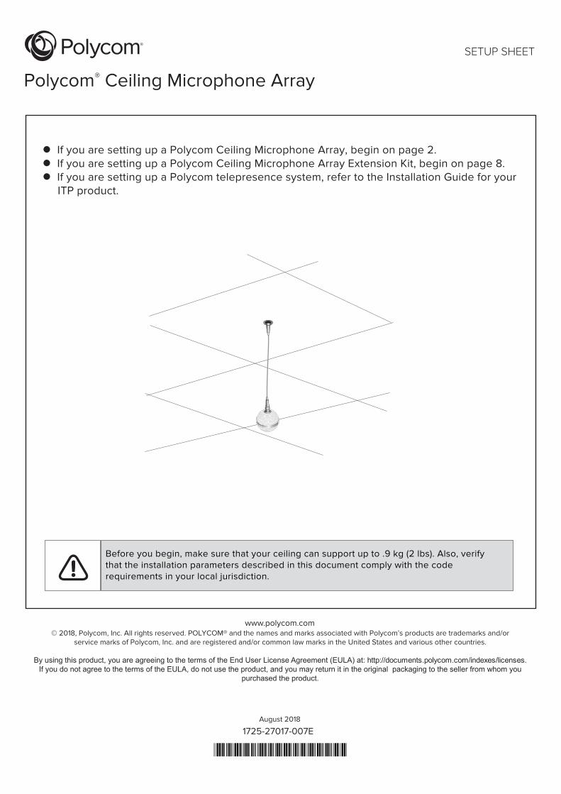
Polycom® Ceiling Microphone Array
SETUP SHEET
1725-27017-007E
If you are setting up a Polycom Ceiling Microphone Array, begin on page 2. If you are setting up a Polycom Ceiling Microphone Array Extension Kit, begin on page 8. If you are setting up a Polycom telepresence system, refer to the Installation Guide for your ITP product.
Before you begin, make sure that your ceiling can support up to .9 kg (2 lbs). Also, verify that the installation parameters described in this document comply with the coderequirements in your local jurisdiction.
2 Polycom Ceiling Microphone Array Setup Sheet
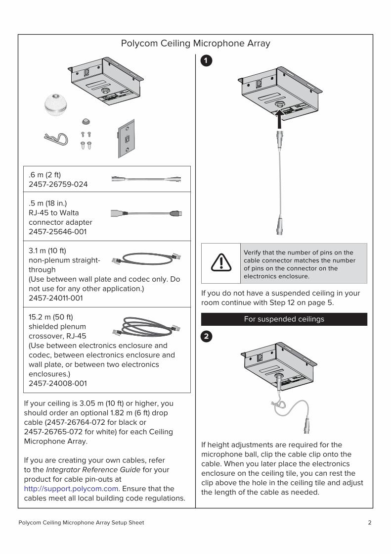
Polycom Ceiling Microphone Array
.6 m (2 ft)2457-26759-024
.5 m (18 in.)RJ-45 to Waltaconnector adapter2457-25646-001
3.1 m (10 ft)non-plenum straight-through (Use between wall plate and codec only. Donot use for any other application.)2457-24011-001
15.2 m (50 ft)shielded plenum crossover, RJ-45(Use between electronics enclosure andcodec, between electronics enclosure andwall plate, or between two electronicsenclosures.)2457-24008-001
If your ceiling is 3.05 m (10 ft) or higher, youshould order an optional 1.82 m (6 ft) dropcable (2457-26764-072 for black or2457-26765-072 for white) for each CeilingMicrophone Array.
If you are creating your own cables, referto the Integrator Reference Guide for yourproduct for cable pin-outs athttp://support.polycom.com. Ensure that thecables meet all local building code regulations.
1
Verify that the number of pins on thecable connector matches the numberof pins on the connector on theelectronics enclosure.
If you do not have a suspended ceiling in yourroom continue with Step 12 on page 5.
For suspended ceilings
2
If height adjustments are required for themicrophone ball, clip the cable clip onto thecable. When you later place the electronicsenclosure on the ceiling tile, you can rest theclip above the hole in the ceiling tile and adjustthe length of the cable as needed.
Polycom Ceiling Microphone Array Setup Sheet 3
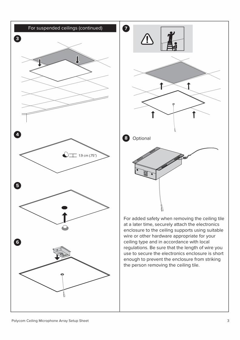
For suspended ceilings (continued)
3
4
1.9 cm (.75”)
5
7
8 Optional
For added safety when removing the ceiling tileat a later time, securely attach the electronics enclosure to the ceiling supports using suitable wire or other hardware appropriate for your ceiling type and in accordance with local regulations. Be sure that the length of wire you use to secure the electronics enclosure is short enough to prevent the enclosure from striking the person removing the ceiling tile.
6

Polycom Ceiling Microphone Array Setup Sheet 4
For suspended ceilings (continued)
9
4.13 cm (1.625”)
.64 cm (.25”) 4.10 cm (1.614”)
4.10 cm (1.614”) .64 cm (.25”)
10
11
12
15.2 m (50’ )
~ 3.1 m(10’)
SoundStructure C16TM

Polycom Ceiling Microphone Array Setup Sheet 5
For ceilings that are not suspended
13
To attach the electronics enclosure, use suitablehardware for your ceiling type. Align theenclosure so that, when the Microphone Arrayis attached, the dot on the Microphone Arraypoints toward the main display, as shown inStep 16.
14
15.2 m (50’ )
~ 3.1 m(10’)
SoundStructure C16TM
For all ceilings
15
16
Point the dot (located on the band around themiddle of the microphone ball) toward the maindisplay.
Polycom EagleEye Director II Setup Sheet 6
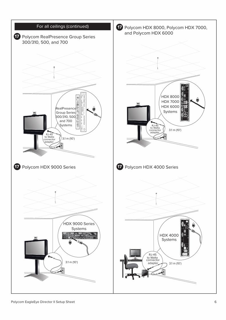
For all ceilings (continued)
17 Polycom RealPresence Group Series300/310, 500, and 700
3.1 m (10’)RJ-45
to Waltaconnectoradapter
12V
6.25
A
21 4
1 2
3
31
2
RealPresenceGroup Series300/310, 500,
and 700Systems
17 Polycom HDX 9000 Series
3.1 m (10’)
HDX 9000 SeriesSystems
17 Polycom HDX 8000, Polycom HDX 7000,and Polycom HDX 6000
44VC
R/D
VD
3
VCR
/DVD
3
AU
X
3.1 m (10’)
HDX 8000HDX 7000HDX 6000
Systems
RJ-45to Walta
connectoradapter
17 Polycom HDX 4000 Series
3.1 m (10’)
100
-240V
AC
50
/60
Hz 2.3ARJ-45
adapter
to Walta connector
HDX 4000Systems
Polycom Ceiling Microphone Array Setup Sheet 7
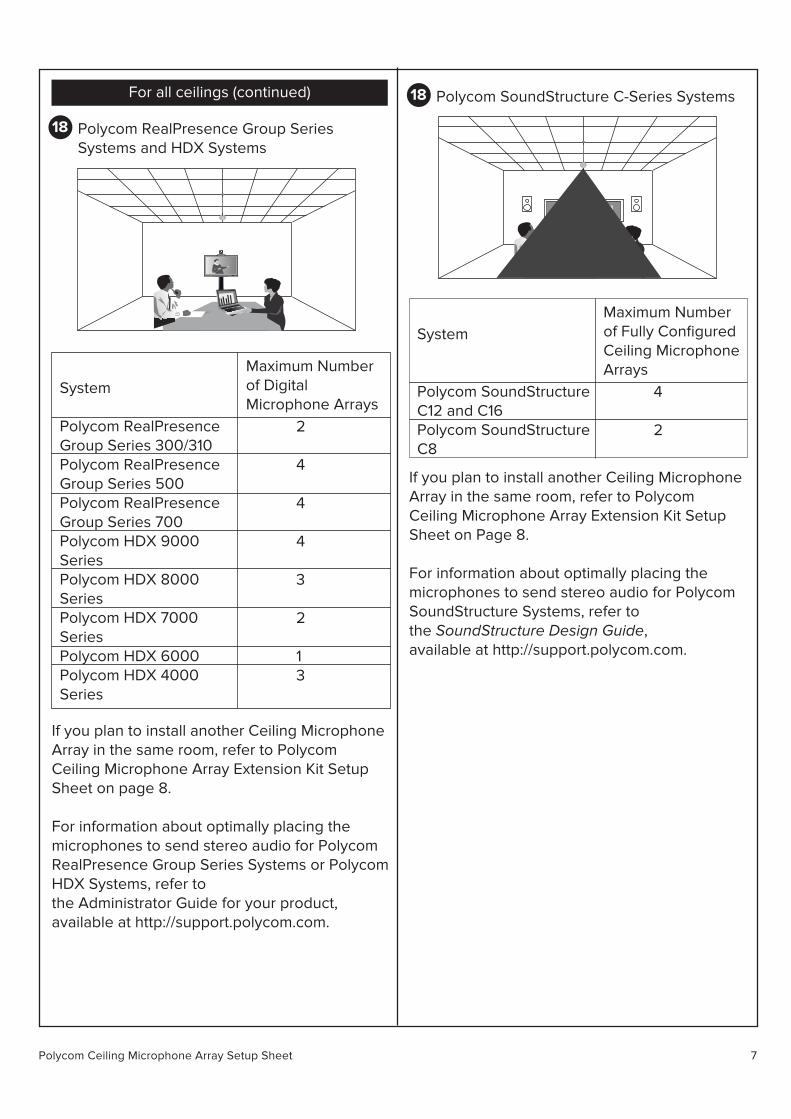
For all ceilings (continued)
18 Polycom RealPresence Group SeriesSystems and HDX Systems
18 Polycom SoundStructure C-Series Systems
If you plan to install another Ceiling Microphone Array in the same room, refer to PolycomCeiling Microphone Array Extension Kit Setup Sheet on page 8.
For information about optimally placing the microphones to send stereo audio for Polycom RealPresence Group Series Systems or PolycomHDX Systems, refer to the Administrator Guide for your product, available at http://support.polycom.com.
System
Polycom RealPresenceGroup Series 300/310Polycom RealPresenceGroup Series 500Polycom RealPresenceGroup Series 700Polycom HDX 9000SeriesPolycom HDX 8000SeriesPolycom HDX 7000SeriesPolycom HDX 6000Polycom HDX 4000Series
2
4
4
4
3
2
13
Maximum Numberof DigitalMicrophone Arrays
If you plan to install another Ceiling Microphone Array in the same room, refer to PolycomCeiling Microphone Array Extension Kit Setup Sheet on Page 8.
For information about optimally placing the microphones to send stereo audio for Polycom SoundStructure Systems, refer to the SoundStructure Design Guide, available at http://support.polycom.com.
System
Polycom SoundStructureC12 and C16Polycom SoundStructureC8
4
2
Maximum Numberof Fully ConfiguredCeiling MicrophoneArrays
8Polycom Ceiling Microphone Array Setup Sheet
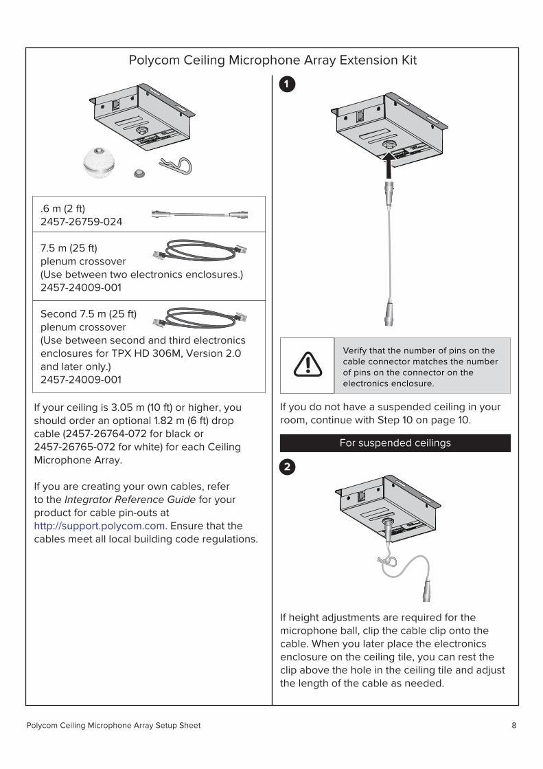
Polycom Ceiling Microphone Array Extension Kit
.6 m (2 ft)2457-26759-024
7.5 m (25 ft)plenum crossover(Use between two electronics enclosures.)2457-24009-001
Second 7.5 m (25 ft)plenum crossover(Use between second and third electronics enclosures for TPX HD 306M, Version 2.0and later only.)2457-24009-001
If your ceiling is 3.05 m (10 ft) or higher, youshould order an optional 1.82 m (6 ft) dropcable (2457-26764-072 for black or2457-26765-072 for white) for each CeilingMicrophone Array.
If you are creating your own cables, referto the Integrator Reference Guide for yourproduct for cable pin-outs athttp://support.polycom.com. Ensure that thecables meet all local building code regulations.
1
Verify that the number of pins on thecable connector matches the numberof pins on the connector on theelectronics enclosure.
If you do not have a suspended ceiling in yourroom, continue with Step 10 on page 10.
For suspended ceilings
2
If height adjustments are required for themicrophone ball, clip the cable clip onto thecable. When you later place the electronicsenclosure on the ceiling tile, you can rest theclip above the hole in the ceiling tile and adjustthe length of the cable as needed.

Polycom Ceiling Microphone Array Setup Sheet 9
For suspended ceilings (continued)
3
7
8 Optional
For added safety when removing the ceiling tileat a later time, securely attach the electronics enclosure to the ceiling supports using suitable wire or other hardware appropriate for your ceiling type and in accordance with local regulations. Be sure that the length of wire you use to secure the electronics enclosure is short enough to prevent the enclosure from striking the person removing the ceiling tile.
4
1.9 cm (.75”)
5
6
Polycom Ceiling Microphone Array Setup Sheet 10
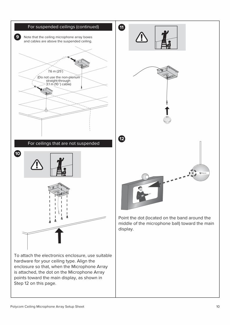
For suspended ceilings (continued)
9
10
11
12
7.6 m (25’)
(Do not use the non-plenum straight-through 3.1 m (10 ‘) cable)
For ceilings that are not suspended
To attach the electronics enclosure, use suitablehardware for your ceiling type. Align theenclosure so that, when the Microphone Arrayis attached, the dot on the Microphone Arraypoints toward the main display, as shown inStep 12 on this page.
Point the dot (located on the band around themiddle of the microphone ball) toward the maindisplay.
Note that the ceiling microphone array boxesand cables are above the suspended ceiling.
Polycom Ceiling Microphone Array Setup Sheet 11
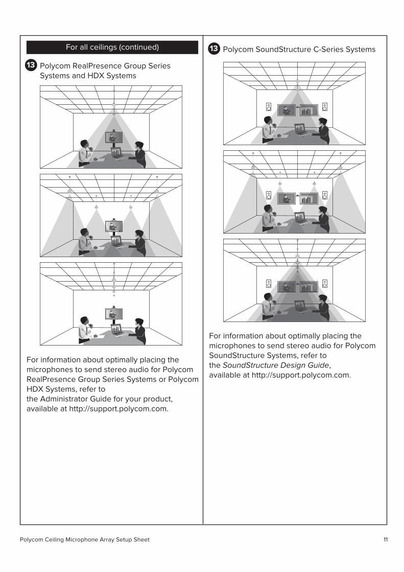
For all ceilings (continued)
13 Polycom RealPresence Group SeriesSystems and HDX Systems
13 Polycom SoundStructure C-Series Systems
For information about optimally placing the microphones to send stereo audio for Polycom RealPresence Group Series Systems or PolycomHDX Systems, refer to the Administrator Guide for your product, available at http://support.polycom.com.
For information about optimally placing the microphones to send stereo audio for Polycom SoundStructure Systems, refer to the SoundStructure Design Guide, available at http://support.polycom.com.