Embed Size (px)
Citation preview
POLARIMETRIC AVIONIC WEATHER RADAR FORINCREASING FLIGHT SAFETY AND EFFICIENCY
Alberto Lupidi∗, Stefano Lischi∗, Fabrizio Berizzi∗, Marco Martorella∗, Fabrizio Cuccoli∗∗RaSS National Laboratory, CNIT (National Inter-University Consortium for
Telecommunications), Pisa, Italy
Keywords: Radar polarimetry, Weather decision making, Electronic Flight Bag, Trajectoryoptimization
Abstract
Current avionic weather radars cannot give accu-rate information about the weather hazards. Pi-lots avoid the potentially dangerous area with agreater detour, but only thirty percent of “redecho” radar returns represent actually a threat.These detours involve a longer trajectory and agreater impact on the environment. Instead, a po-larimetric radar, which can discriminate for in-stance between rain and hail, can enhance pilotsituational awareness and support trajectory op-timization. In the framework of KLEAN projectfunded by CLEANSKY Joint Technology Initia-tive, a customized knowledge-based ElectronicFlight Bag (EFB) was developed. This EFB,other than being capable to show the map, theflight trajectory and information about surround-ing environment, it also implements a polarimet-ric radar data processor aimed to the assessmentof the risk level of the phenomena encountereden route.
1 Introduction
Weather factors cause hazards to flight in anyof its phases. Usually only a small fraction ofaccidents due to bad weather conditions occursduring the cruise phase, which is the largest partof an aircraft flight time. On the other hand,most accidents happen during the takeoff or thelanding operations. Trajectory changes due tobad weather conditions, with related longer flightpaths and increased fuel consumption, mainly
occur in the cruise phase, including subsequentdecision about detour on a different arrivalairport [1]. Some studies highlight the possibilityof a controlled trajectory change rather than acomplete avoidance in case of bad weather event.Wu et al. stated in [2] that it appears that pilotsdo make an effort in maintaining a safe distancefrom weather when the encountered circum-stances make it easy to achieve, such as whenthe initial trajectories were at the boundaries ofthe leading or trailing edges of the storms. Whenthe encounter circumstances make it inefficientto fly around the hazardous region altogether,such as when the initial trajectories take themthrough the middle of a line of storm cells, pilotswould be more willing to fly closer to the stormsto trade off comfort for efficiency.DeLaura et al. showed in [3] that often, dueto the lack of precise information on weatherstructure, pilots make a large deviation in aregion of benign weather, up to more than100 km downwind from nearest convectivecell. Moreover, they highlighted the fact thatadditional and relevant weather data, like a moreprecise information on the internal structureof the event or presence of organized versusdisorganized convection is present, would bebeneficial.
In this paper we present some enhance-ments for a class 2 type B EFB which consistif several aspects; the weather representationis extended with respect to classical weatherradar acquisition with the introduction of radar
1
LUPIDI, LISCHI, BERIZZI, MARTORELLA, CUCCOLI
polarimetry. Using this technique it is possibleto understand more accurately what lies withinthe core of a phenomenon, and to classifydifferent types of hydrometeors like hail (one ofthe most dangerous weather phenomena), rain(usually non-dangerous) or snow [4]. Therefore,taking into account the estimated level of risk,it is possible to calculate more efficient routes.Furthermore, the use of polarimetry provides astronger immunity against clutter and noise [5].The system is implemented in aNexisTMElectronic Flight Bag developed bythe Astronautic Corporation of America. Thepackage is show in Fig.1
Fig. 1 NexisTMEFB system.
2 System Architecture and Functionality
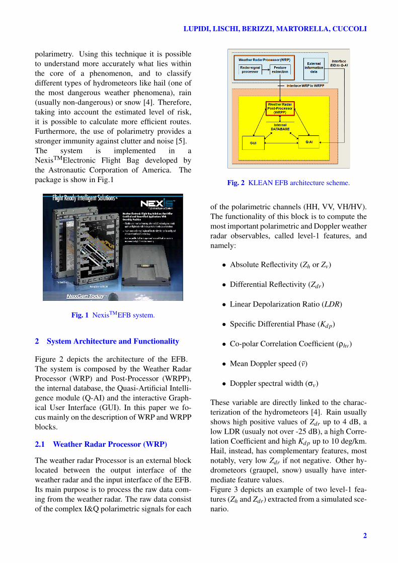
Figure 2 depicts the architecture of the EFB.The system is composed by the Weather RadarProcessor (WRP) and Post-Processor (WRPP),the internal database, the Quasi-Artificial Intelli-gence module (Q-AI) and the interactive Graph-ical User Interface (GUI). In this paper we fo-cus mainly on the description of WRP and WRPPblocks.
2.1 Weather Radar Processor (WRP)
The weather radar Processor is an external blocklocated between the output interface of theweather radar and the input interface of the EFB.Its main purpose is to process the raw data com-ing from the weather radar. The raw data consistof the complex I&Q polarimetric signals for each
Fig. 2 KLEAN EFB architecture scheme.
of the polarimetric channels (HH, VV, VH/HV).The functionality of this block is to compute themost important polarimetric and Doppler weatherradar observables, called level-1 features, andnamely:
• Absolute Reflectivity (Zh or Zv)
• Differential Reflectivity (Zdr)
• Linear Depolarization Ratio (LDR)
• Specific Differential Phase (Kd p)
• Co-polar Correlation Coefficient (ρhv)
• Mean Doppler speed (v̄)
• Doppler spectral width (σv)
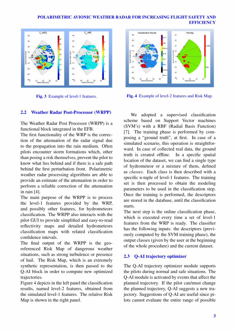
These variable are directly linked to the charac-terization of the hydrometeors [4]. Rain usuallyshows high positive values of Zdr up to 4 dB, alow LDR (usualy not over -25 dB), a high Corre-lation Coefficient and high Kd p up to 10 deg/km.Hail, instead, has complementary features, mostnotably, very low Zdr if not negative. Other hy-drometeors (graupel, snow) usually have inter-mediate feature values.Figure 3 depicts an example of two level-1 fea-tures (Zh and Zdr) extracted from a simulated sce-nario.
2
POLARIMETRIC AVIONIC WEATHER RADAR FOR INCREASING FLIGHT SAFETY ANDEFFICIENCY
Fig. 3 Example of level-1 features.
2.2 Weather Radar Post-Processor (WRPP)
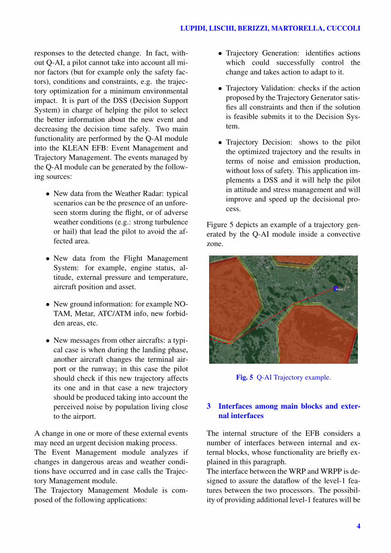
The Weather Radar Post Processor (WRPP) is afunctional block integrated in the EFB.The first functionality of the WRP is the correc-tion of the attenuation of the radar signal dueto the propagation into the rain medium. Oftenpilots encounter storm formations which, otherthan posing a risk themselves, prevent the pilot toknow what lies behind and if there is a safe pathbehind the first perturbation front. Polarimetricweather radar processing algorithms are able toprovide an estimate of the attenuation in order toperform a reliable correction of the attenuationin rain [4].The main purpose of the WRPP is to processthe level-1 features provided by the WRP,and possibly other features, for hydrometeorsclassification. The WRPP also interacts with thepilot GUI to provide simplified and easy-to-readreflectivity maps and detailed hydrometeorsclassification maps with related classificationconfidence intevals.The final output of the WRPP is the geo-referenced Risk Map of dangerous weathersituations, such as strong turbulence or presenceof hail. The Risk Map, which is an extremelysynthetic representation, is then passed to theQ-AI block in order to compute new optimizedtrajectories.Figure 4 depicts in the left panel the classificationresults, named level-2 features, obtained fromthe simulated level-1 features. The relative RiskMap is shown in the right panel.
Fig. 4 Example of level-2 features and Risk Map.
We adopted a supervised classificationscheme based on Support Vector machines(SVM’s) with a RBF (Radial Basis Function)[7]. The training phase is performed by com-posing a “ground truth”, at first. In case of asimulated scenario, this operation is straightfor-ward. In case of collected real data, the groundtruth is created offline. In a specific spatiallocation of the dataset, we can find a single typeof hydrometeor or a mixture of them, definedas classes. Each class is then described with aspecific n-tuple of level-1 features. The trainingset is then processed to obtain the modelingparameters to be used in the classification step.Once the training is performed, the descriptorsare stored in the database, until the classificationstarts.The next step is the online classification phase,which is executed every time a set of level-1features from the WRP is ready. The classifierhas the following inputs: the descriptors (previ-ously computed by the SVM training phase), theoutput classes (given by the user at the beginningof the whole procedure) and the current dataset.
2.3 Q-AI trajectory optimizer
The Q-AI trajectory optimizer module supportsthe pilots during normal and safe situations. TheQ-AI module is activated by events that affect theplanned trajectory. If the pilot can/must changethe planned trajectory, Q-AI suggests a new tra-jectory. Suggestions of Q-AI are useful since pi-lots cannot evaluate the entire range of possible
3
LUPIDI, LISCHI, BERIZZI, MARTORELLA, CUCCOLI
responses to the detected change. In fact, with-out Q-AI, a pilot cannot take into account all mi-nor factors (but for example only the safety fac-tors), conditions and constraints, e.g. the trajec-tory optimization for a minimum environmentalimpact. It is part of the DSS (Decision SupportSystem) in charge of helping the pilot to selectthe better information about the new event anddecreasing the decision time safely. Two mainfunctionality are performed by the Q-AI moduleinto the KLEAN EFB: Event Management andTrajectory Management. The events managed bythe Q-AI module can be generated by the follow-ing sources:
• New data from the Weather Radar: typicalscenarios can be the presence of an unfore-seen storm during the flight, or of adverseweather conditions (e.g.: strong turbulenceor hail) that lead the pilot to avoid the af-fected area.
• New data from the Flight ManagementSystem: for example, engine status, al-titude, external pressure and temperature,aircraft position and asset.
• New ground information: for example NO-TAM, Metar, ATC/ATM info, new forbid-den areas, etc.
• New messages from other aircrafts: a typi-cal case is when during the landing phase,another aircraft changes the terminal air-port or the runway; in this case the pilotshould check if this new trajectory affectsits one and in that case a new trajectoryshould be produced taking into account theperceived noise by population living closeto the airport.
A change in one or more of these external eventsmay need an urgent decision making process.The Event Management module analyzes ifchanges in dangerous areas and weather condi-tions have occurred and in case calls the Trajec-tory Management module.The Trajectory Management Module is com-posed of the following applications:
• Trajectory Generation: identifies actionswhich could successfully control thechange and takes action to adapt to it.
• Trajectory Validation: checks if the actionproposed by the Trajectory Generator satis-fies all constraints and then if the solutionis feasible submits it to the Decision Sys-tem.
• Trajectory Decision: shows to the pilotthe optimized trajectory and the results interms of noise and emission production,without loss of safety. This application im-plements a DSS and it will help the pilotin attitude and stress management and willimprove and speed up the decisional pro-cess.
Figure 5 depicts an example of a trajectory gen-erated by the Q-AI module inside a convectivezone.
Fig. 5 Q-AI Trajectory example.
3 Interfaces among main blocks and exter-nal interfaces
The internal structure of the EFB considers anumber of interfaces between internal and ex-ternal blocks, whose functionality are briefly ex-plained in this paragraph.The interface between the WRP and WRPP is de-signed to assure the dataflow of the level-1 fea-tures between the two processors. The possibil-ity of providing additional level-1 features will be
4
POLARIMETRIC AVIONIC WEATHER RADAR FOR INCREASING FLIGHT SAFETY ANDEFFICIENCY
investigated in future works.In order to evaluate the optimal trajectories thatminimize emissions, the Q-AI retrieves informa-tion from the external connections, about: pre-defined route, allowed flight corridor (airspacewhere to look for alternative routes), no-flightzones, NOTAMs, forecasted and updated weatherconditions (wind, temperature, pressure, rain,storms, etc.), aircraft performance models andparameters, flight condition (speed, altitude,aerodynamic state, engine state, etc.).For the correct functioning of the trajectory deci-sion algorithm, the Q-AI module requires somepre-assigned data which are provided by the in-ternal database. These data consist of: predefinedtravel route, route way-points, departure and ar-rival airports, total travel time, aircraft type forthrust and fuel flow estimation, CO2 and NOxemissions and noise factor. From the InternalDatabase, the Q-AI acquires also some infor-mation about the current flight status, namelycurrent position (latitude, longitude and height),speed, bearing and current time. Moreover, theInternal database provides also some informationabout the current weather and atmospheric status
• Weather conditions (initial input, to be up-dated with forecasts)
• Pressure, temperature, air density, relativehumidity
• Wind field structure
The Internal Database is also linked with theWRPP in order to have access to some of themeteorological features. The interface with theWRPP provides also the forbidden flight zonedue to dangerous weather situations, like strongturbulence or hail. The general reflectivity mapcan also be provided, in case of need, by groundbased weather radar, where normally is provideddirectly from the on-board radar. The polarimet-ric features processing needs a front-end with theuser (GUI). In this context, besides the other util-ity of the GUI, a section must be dedicated tothe visual output of the resulting mapping and,after the interaction with the Q-AI module, theevaluation of the risk map. The latter, combined
with the mapping of the phenomena, providesa degree of risk associated to a particular phe-nomenon occurring in a specific location of theobserved space volume. The classification resultscan be also stored in the internal database in orderto be constantly accessible by the Q-AI module ifthe pilot needs them.
4 Test Scenario, WRP and WRPP operation
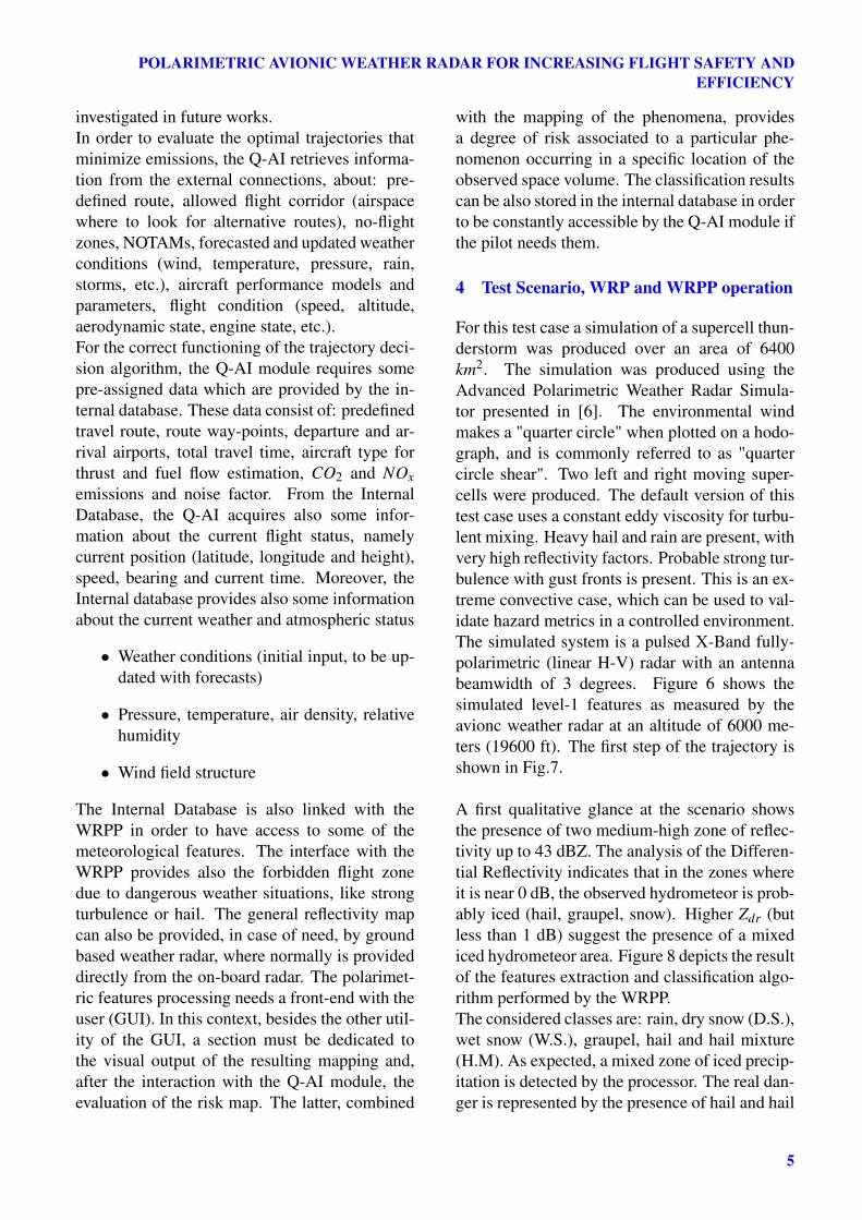
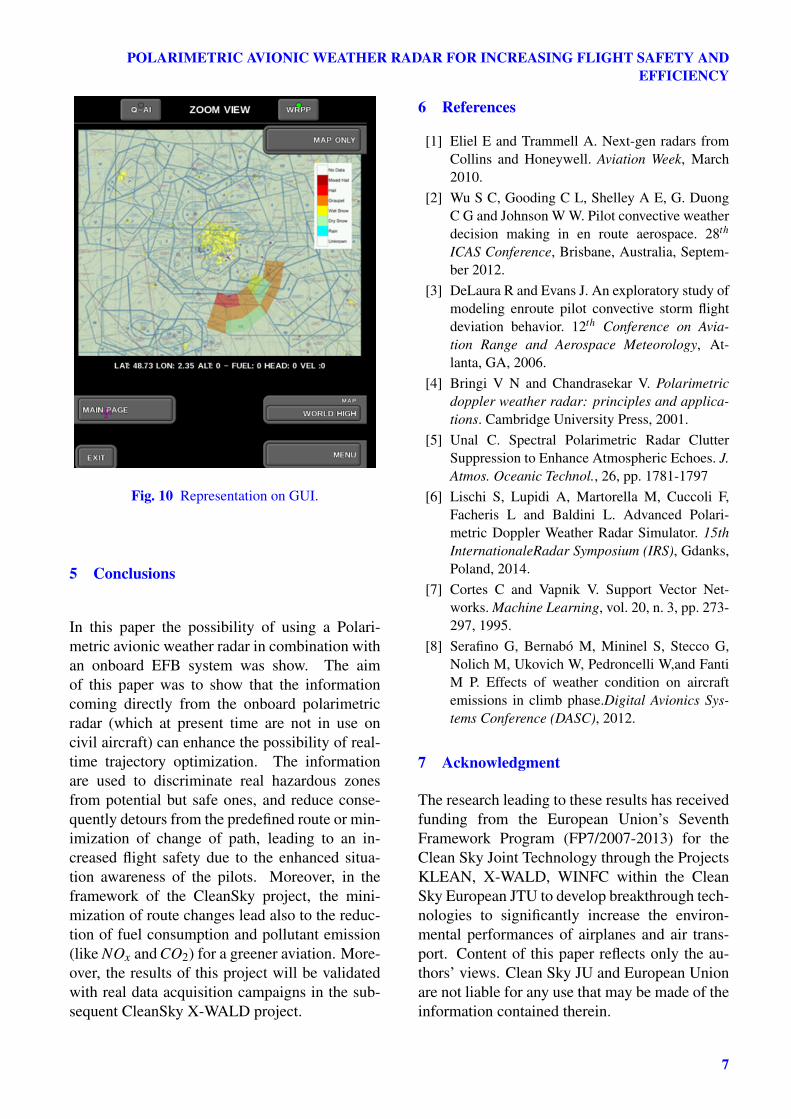
For this test case a simulation of a supercell thun-derstorm was produced over an area of 6400km2. The simulation was produced using theAdvanced Polarimetric Weather Radar Simula-tor presented in [6]. The environmental windmakes a "quarter circle" when plotted on a hodo-graph, and is commonly referred to as "quartercircle shear". Two left and right moving super-cells were produced. The default version of thistest case uses a constant eddy viscosity for turbu-lent mixing. Heavy hail and rain are present, withvery high reflectivity factors. Probable strong tur-bulence with gust fronts is present. This is an ex-treme convective case, which can be used to val-idate hazard metrics in a controlled environment.The simulated system is a pulsed X-Band fully-polarimetric (linear H-V) radar with an antennabeamwidth of 3 degrees. Figure 6 shows thesimulated level-1 features as measured by theavionc weather radar at an altitude of 6000 me-ters (19600 ft). The first step of the trajectory isshown in Fig.7.
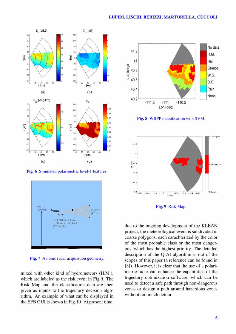
A first qualitative glance at the scenario showsthe presence of two medium-high zone of reflec-tivity up to 43 dBZ. The analysis of the Differen-tial Reflectivity indicates that in the zones whereit is near 0 dB, the observed hydrometeor is prob-ably iced (hail, graupel, snow). Higher Zdr (butless than 1 dB) suggest the presence of a mixediced hydrometeor area. Figure 8 depicts the resultof the features extraction and classification algo-rithm performed by the WRPP.The considered classes are: rain, dry snow (D.S.),wet snow (W.S.), graupel, hail and hail mixture(H.M). As expected, a mixed zone of iced precip-itation is detected by the processor. The real dan-ger is represented by the presence of hail and hail
5
LUPIDI, LISCHI, BERIZZI, MARTORELLA, CUCCOLI
(a) (b)
(c) (d)
Fig. 6 Simulated polarimetric level-1 features.
Fig. 7 Avionic radar acquisition geometry.
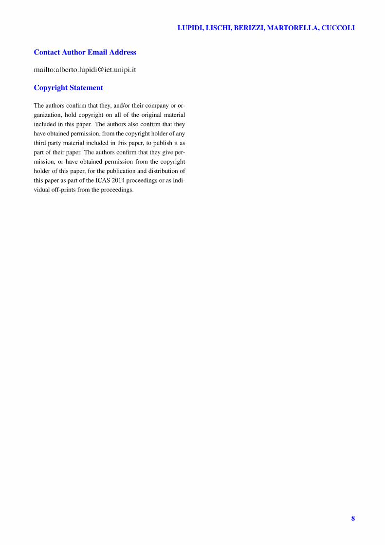
mixed with other kind of hydrometeors (H.M.),which are labeled as the risk event in Fig.9. TheRisk Map and the classification data are thengiven as inputs to the trajectory decision algo-rithm. An example of what can be displayed inthe EFB GUI is shown in Fig.10. At present time,
Fig. 8 WRPP classification with SVM.
Fig. 9 Risk Map.
due to the ongoing development of the KLEANproject, the meteorological event is subdivided incoarse polygons, each carachterized by the colorof the most probable class or the most danger-ous, which has the highest priority. The detaileddescription of the Q-AI algorithm is out of thescopes of this paper (a reference can be found in[8]). However, it is clear that the use of a polari-metric radar can enhance the capabilities of thetrajectory optimization software, which can beused to detect a safe path through non-dangerouszones or design a path around hazardous zoneswithout too much detour.
6
POLARIMETRIC AVIONIC WEATHER RADAR FOR INCREASING FLIGHT SAFETY ANDEFFICIENCY
Fig. 10 Representation on GUI.
5 Conclusions
In this paper the possibility of using a Polari-metric avionic weather radar in combination withan onboard EFB system was show. The aimof this paper was to show that the informationcoming directly from the onboard polarimetricradar (which at present time are not in use oncivil aircraft) can enhance the possibility of real-time trajectory optimization. The informationare used to discriminate real hazardous zonesfrom potential but safe ones, and reduce conse-quently detours from the predefined route or min-imization of change of path, leading to an in-creased flight safety due to the enhanced situa-tion awareness of the pilots. Moreover, in theframework of the CleanSky project, the mini-mization of route changes lead also to the reduc-tion of fuel consumption and pollutant emission(like NOx and CO2) for a greener aviation. More-over, the results of this project will be validatedwith real data acquisition campaigns in the sub-sequent CleanSky X-WALD project.
6 References
[1] Eliel E and Trammell A. Next-gen radars fromCollins and Honeywell. Aviation Week, March2010.
[2] Wu S C, Gooding C L, Shelley A E, G. DuongC G and Johnson W W. Pilot convective weatherdecision making in en route aerospace. 28th
ICAS Conference, Brisbane, Australia, Septem-ber 2012.
[3] DeLaura R and Evans J. An exploratory study ofmodeling enroute pilot convective storm flightdeviation behavior. 12th Conference on Avia-tion Range and Aerospace Meteorology, At-lanta, GA, 2006.
[4] Bringi V N and Chandrasekar V. Polarimetricdoppler weather radar: principles and applica-tions. Cambridge University Press, 2001.
[5] Unal C. Spectral Polarimetric Radar ClutterSuppression to Enhance Atmospheric Echoes. J.Atmos. Oceanic Technol., 26, pp. 1781-1797
[6] Lischi S, Lupidi A, Martorella M, Cuccoli F,Facheris L and Baldini L. Advanced Polari-metric Doppler Weather Radar Simulator. 15thInternationaleRadar Symposium (IRS), Gdanks,Poland, 2014.
[7] Cortes C and Vapnik V. Support Vector Net-works. Machine Learning, vol. 20, n. 3, pp. 273-297, 1995.
[8] Serafino G, Bernabó M, Mininel S, Stecco G,Nolich M, Ukovich W, Pedroncelli W,and FantiM P. Effects of weather condition on aircraftemissions in climb phase.Digital Avionics Sys-tems Conference (DASC), 2012.
7 Acknowledgment
The research leading to these results has receivedfunding from the European Union’s SeventhFramework Program (FP7/2007-2013) for theClean Sky Joint Technology through the ProjectsKLEAN, X-WALD, WINFC within the CleanSky European JTU to develop breakthrough tech-nologies to significantly increase the environ-mental performances of airplanes and air trans-port. Content of this paper reflects only the au-thors’ views. Clean Sky JU and European Unionare not liable for any use that may be made of theinformation contained therein.
7
LUPIDI, LISCHI, BERIZZI, MARTORELLA, CUCCOLI
Contact Author Email Address
mailto:[email protected]
Copyright Statement
The authors confirm that they, and/or their company or or-ganization, hold copyright on all of the original materialincluded in this paper. The authors also confirm that theyhave obtained permission, from the copyright holder of anythird party material included in this paper, to publish it aspart of their paper. The authors confirm that they give per-mission, or have obtained permission from the copyrightholder of this paper, for the publication and distribution ofthis paper as part of the ICAS 2014 proceedings or as indi-vidual off-prints from the proceedings.
8