Embed Size (px)
Citation preview

PNOZ m ES ETH
Operating Manual1002700EN04
Configurable Control System PNOZmulti

PrefaceThis document is a translation of the original document.
All rights to this documentation are reserved by Pilz GmbH & Co. KG. Copies may be madefor internal purposes. Suggestions and comments for improving this documentation will begratefully received.
Pilz®, PIT®, PMI®, PNOZ®, Primo®, PSEN®, PSS®, PVIS®, SafetyBUS p®,SafetyEYE®, SafetyNET p®, the spirit of safety® are registered and protected trademarksof Pilz GmbH & Co. KG in some countries.
SD means Secure Digital
Content
Operating Manual PNOZ m ES ETH1002700EN04
3
Section 1 Introduction 41.1 Validity of documentation 41.2 Retaining the documentation 41.3 Definition of symbols 4
Section 2 Overview 62.1 Scope of delivery 62.2 Unit features 62.3 Front view 7
Section 3 Safety 83.1 Intended use 83.2 System requirements 83.3 Safety regulations 83.3.1 Use of qualified personnel 83.3.2 Warranty and liability 93.3.3 Disposal 93.3.4 For your safety 9
Section 4 Function description 104.1 Unit properties 104.2 Block diagram 10
Section 5 Installation 115.1 General installation guidelines 115.2 Dimensions 115.3 Connecting the base unit and expansion modules 11
Section 6 Commissioning 136.1 General wiring guidelines 136.2 Preparing for operation 136.3 Download modified project to the PNOZmulti safety system 136.4 Ethernet interfaces 136.4.1 RJ45 interfaces ("Ethernet") 136.4.2 Requirements of the connection cable and connector 146.4.3 Interface configuration 146.4.4 RJ45 connection cable 156.4.5 Process data exchange 16
Section 7 Operation 177.1 Messages 177.2 Reset Ethernet connection settings 18
Section 8 Tecnical details 19
Section 9 Order reference 219.1 Module 219.2 Accessories 21
Introduction
Operating Manual PNOZ m ES ETH1002700EN04
4
1 Introduction
1.1 Validity of documentationThis documentation is valid for the product PNOZ m ES ETH. It is valid until new documentation is published.
This operating manual explains the function and operation, describes the installation andprovides guidelines on how to connect the product.
1.2 Retaining the documentationThis documentation is intended for instruction and should be retained for future reference.
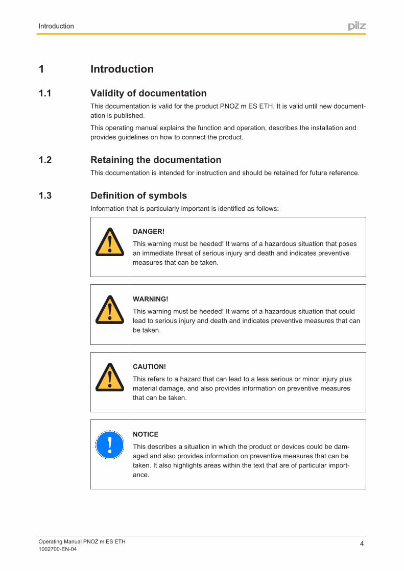
1.3 Definition of symbolsInformation that is particularly important is identified as follows:
DANGER!
This warning must be heeded! It warns of a hazardous situation that posesan immediate threat of serious injury and death and indicates preventivemeasures that can be taken.
WARNING!
This warning must be heeded! It warns of a hazardous situation that couldlead to serious injury and death and indicates preventive measures that canbe taken.
CAUTION!
This refers to a hazard that can lead to a less serious or minor injury plusmaterial damage, and also provides information on preventive measuresthat can be taken.
NOTICE
This describes a situation in which the product or devices could be damaged and also provides information on preventive measures that can betaken. It also highlights areas within the text that are of particular importance.
Introduction
Operating Manual PNOZ m ES ETH1002700EN04
5
INFORMATION
This gives advice on applications and provides information on special features.

Overview
Operating Manual PNOZ m ES ETH1002700EN04
6
2 Overview
2.1 Scope of delivery} Expansion modulePNOZ m ES ETH
} Jumper 779 260
2.2 Unit featuresUsing the product PNOZ m ES ETH:
Communication module for connection to a base unit from the configurable control systemPNOZmulti 2.
The product has the following features:
} Can be configured in the PNOZmulti Configurator
} 2 Ethernet interfaces
} Status indicators for supply voltage, communication and errors
} Max. 1 communication module can be connected to the left of the base unit PNOZmulti2
} Please refer to the document "PNOZmulti System Expansion" for the PNOZmulti baseunits that can be connected
Overview
Operating Manual PNOZ m ES ETH1002700EN04
7
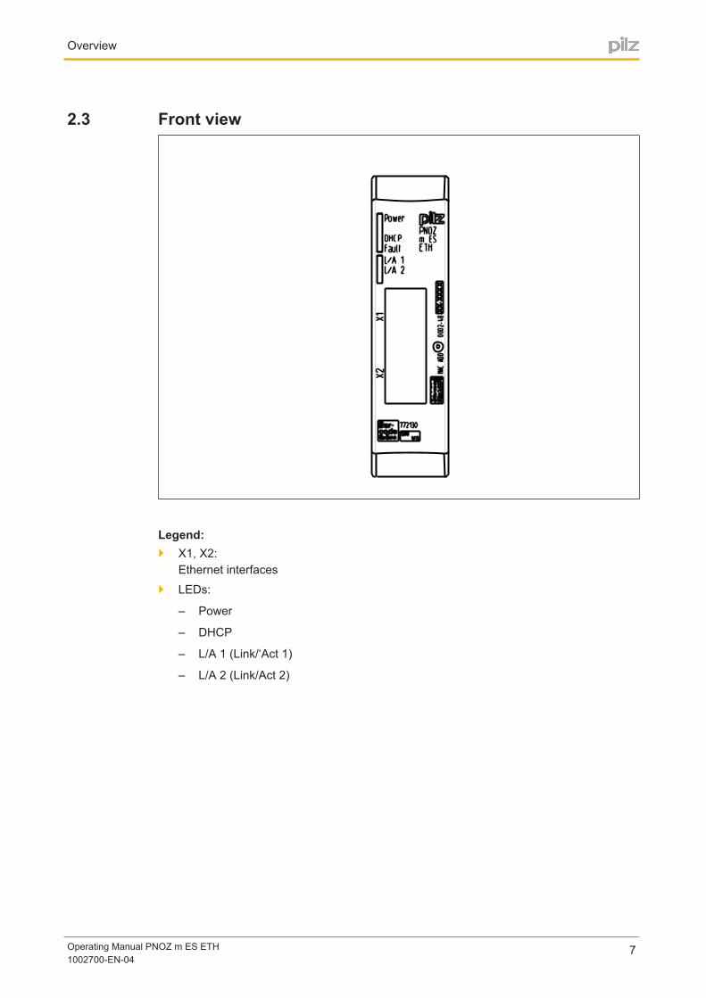
2.3 Front view
Legend:} X1, X2:
Ethernet interfaces
} LEDs:
– Power
– DHCP
– L/A 1 (Link/‘Act 1)
– L/A 2 (Link/Act 2)
Safety
Operating Manual PNOZ m ES ETH1002700EN04
8
3 Safety
3.1 Intended useThe expansion module PNOZ m ES ETH is used for communication of the configurable control system PNOZmulti 2 via Ethernet.
The expansion module may only be connected to a base unit from the configurable controlsystem PNOZmulti 2 (please refer to the document "PNOZmulti System Expansion" for details of the base units that can be connected).
The configurable control system PNOZmulti 2 is used for the safetyrelated interruption ofsafety circuits and is designed for use in:
} ESTOP equipment
} Safety circuits in accordance with VDE 0113 Part 1 and EN 602041
The expansion module may not be used for safetyrelated functions.
Intended use includes making the electrical installation EMCcompliant. The product is designed for use in an industrial environment. It is not suitable for use in a domestic environment, as this can lead to interference.
The following is deemed improper use in particular:
} Any component, technical or electrical modification to the product
} Use of the product outside the areas described in this manual
} Use of the product outside the technical details (see chapter entitled “Technical Details”)
3.2 System requirementsPlease refer to the "Product Modifications" document in the "Version overview" section fordetails of which versions of the base unit and PNOZmulti Configurator can be used for thisproduct.
3.3 Safety regulations
3.3.1 Use of qualified personnelThe products may only be assembled, installed, programmed, commissioned, operated,maintained and decommissioned by competent persons.
A competent person is someone who, because of their training, experience and current professional activity, has the specialist knowledge required to test, assess and operate thework equipment, devices, systems, plant and machinery in accordance with the generalstandards and guidelines for safety technology.
It is the company’s responsibility only to employ personnel who:
} Are familiar with the basic regulations concerning health and safety / accident prevention
} Have read and understood the information provided in this description under "Safety"
} And have a good knowledge of the generic and specialist standards applicable to thespecific application.
Safety
Operating Manual PNOZ m ES ETH1002700EN04
9
3.3.2 Warranty and liabilityAll claims to warranty and liability will be rendered invalid if
} The product was used contrary to the purpose for which it is intended
} Damage can be attributed to not having followed the guidelines in the manual
} Operating personnel are not suitably qualified
} Any type of modification has been made (e.g. exchanging components on the PCBboards, soldering work etc.).
3.3.3 Disposal} In safetyrelated applications, please comply with the mission time tM in the safetyre
lated characteristic data.
} When decommissioning, please comply with local regulations regarding the disposal ofelectronic devices (e.g. Electrical and Electronic Equipment Act).
3.3.4 For your safetyThe unit meets all necessary conditions for safe operation. However, you should always ensure that the following safety requirements are met:
} This operating manual only describes the basic functions of the unit. Information on theadvanced functions can be found in the online help for the PNOZmulti Configurator andin the PNOZmulti technical catalogue. Only use these functions after you have read andunderstood the documentation. All necessary documentation can be found on thePNOZmulti Configurator CD.
} Do not open the housing or make any unauthorised modifications.
} Please make sure you shut down the supply voltage when performing maintenancework (e.g. exchanging contactors).

Function description
Operating Manual PNOZ m ES ETH1002700EN04
10
4 Function description
4.1 Unit propertiesThe product PNOZ m ES ETH has two Ethernet interfaces to
} Download the project
} Read the diagnostic data
} Set virtual inputs for standard functions
} Read virtual outputs for standard functions
via Ethernet (TCP/IP, Modbus/TCP).
Information on diagnostics via the Ethernet interfaces can be found in the document entitled" PNOZmulti 2 communication interfaces".
The connection to Ethernet is made via the two 8pin RJ45 sockets.
The Ethernet interface is configured in the PNOZmulti Configurator and is described in theonline help for the PNOZmulti Configurator.
4.2 Block diagram
Ba
se
un
it
Eth
ern
et

Installation
Operating Manual PNOZ m ES ETH1002700EN04
11
5 Installation
5.1 General installation guidelines} The unit should be installed in a single mounting area with a protection type of at least
IP54.
} Fit the safety system to a horizontal mounting rail. The venting slots must face upwardsand downwards. Other mounting positions could destroy the safety system.
} Use the locking slide on the rear of the unit to attach it to a mounting rail.
} In environments exposed to heavy vibration, the unit should be secured using a fixingelement (e.g. retaining bracket or end angle).
} Open the locking slide before lifting the unit from the mounting rail.
} To comply with EMC requirements, the mounting rail must have a low impedance connection to the control cabinet housing.
} The ambient temperature of the PNOZmulti units in the control cabinet must not exceedthe figure stated in the technical details, otherwise air conditioning will be required.
CAUTION!
Damage due to electrostatic discharge!
Electrostatic discharge can damage components. Ensure against dischargebefore touching the product, e.g. by touching an earthed, conductive surface or by wearing an earthed armband.
5.2 Dimensions
101,4 (4,11“)
111
,0 (
4,3
7“)
22,5
(0,88“)
5.3 Connecting the base unit and expansion modulesConnect the base unit and the expansion module as described in the operating instructionsfor the base units.
} Install the expansion module in the position in which it is configured in the PNOZmultiConfigurator.

Installation
Operating Manual PNOZ m ES ETH1002700EN04
12
} Connect the base unit and expansion modules using the yellow/black jumper.
} Connect the black/yellow terminator to the expansion module.

Commissioning
Operating Manual PNOZ m ES ETH1002700EN04
13
6 Commissioning
6.1 General wiring guidelinesThe wiring is defined in the circuit diagram of the PNOZmulti Configurator.
Please note:
} Information given in the "Technical details" must be followed.
} Use copper wire that can withstand 75°C.
6.2 Preparing for operationDetection and activation of the Ethernet interface, depending on the USB interface on thebase unit:
} USB interface on the base unit not connectedIf the USB interface on the base unit is not connected, the Ethernet interface will be detected and activated by the base unit as soon as the communication module has beenconnected to the base unit.
} USB interface on the base unit connectedIf the USB interface on the base unit is already connected, the "Ethernet" interface willfirst need to be selected on the base unit display to enable the Ethernet interface on thebase unit to be detected and activated (see operating manual for the base unit for details of the setting).
6.3 Download modified project to the PNOZmulti safety systemAs soon as an additional expansion module has been connected to the system, the projectmust be amended using the PNOZmulti Configurator. Proceed as described in the operating instructions for the base unit.
NOTICE
For the commissioning and after every program change, you must checkwhether the safety devices are functioning correctly.
6.4 Ethernet interfaces
6.4.1 RJ45 interfaces ("Ethernet")Two free switch ports are provided as Ethernet interfaces via an internal autosensingswitch. The autosensing switch automatically detects whether data transfer is occurring at10 Mbit/s or 100 Mbit/s.
Commissioning
Operating Manual PNOZ m ES ETH1002700EN04
14
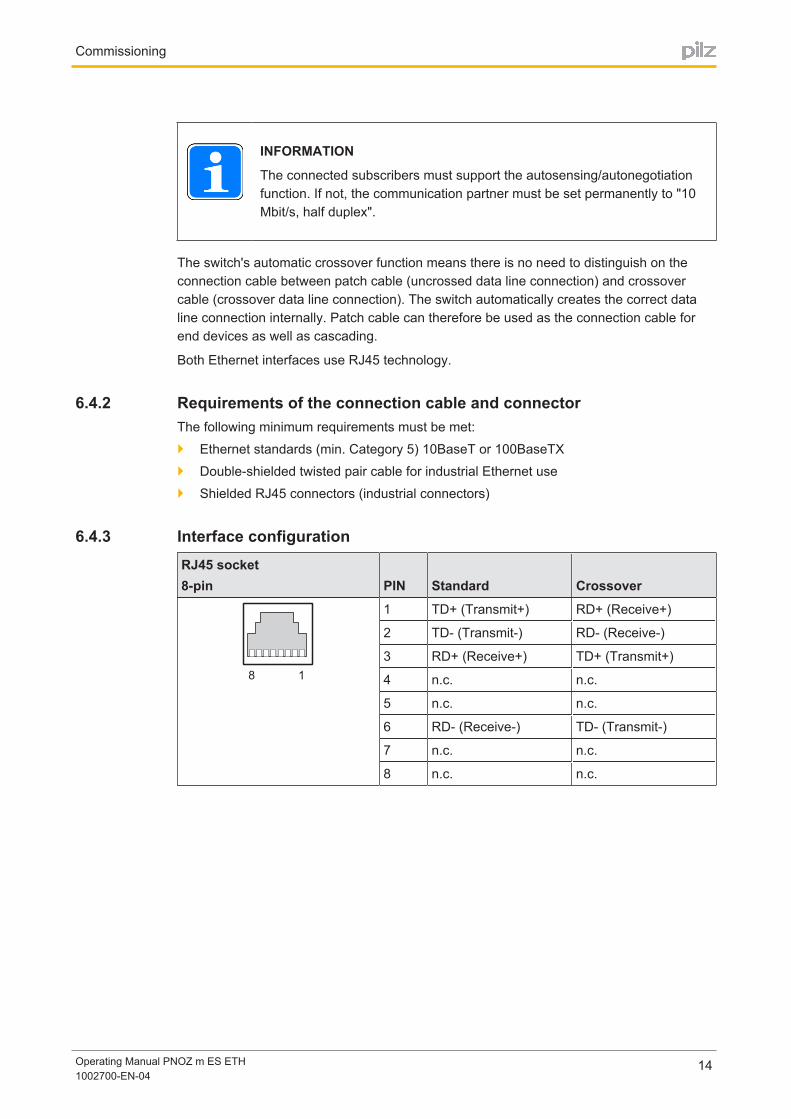
INFORMATION
The connected subscribers must support the autosensing/autonegotiationfunction. If not, the communication partner must be set permanently to "10Mbit/s, half duplex".
The switch's automatic crossover function means there is no need to distinguish on theconnection cable between patch cable (uncrossed data line connection) and crossovercable (crossover data line connection). The switch automatically creates the correct dataline connection internally. Patch cable can therefore be used as the connection cable forend devices as well as cascading.
Both Ethernet interfaces use RJ45 technology.
6.4.2 Requirements of the connection cable and connectorThe following minimum requirements must be met:
} Ethernet standards (min. Category 5) 10BaseT or 100BaseTX
} Doubleshielded twisted pair cable for industrial Ethernet use
} Shielded RJ45 connectors (industrial connectors)
6.4.3 Interface configurationRJ45 socket8pin PIN Standard Crossover
8 1
1 TD+ (Transmit+) RD+ (Receive+)
2 TD (Transmit) RD (Receive)
3 RD+ (Receive+) TD+ (Transmit+)
4 n.c. n.c.
5 n.c. n.c.
6 RD (Receive) TD (Transmit)
7 n.c. n.c.
8 n.c. n.c.

Commissioning
Operating Manual PNOZ m ES ETH1002700EN04
15
6.4.4 RJ45 connection cableRJ45 connector8pin
8
1
10BaseT cable or 100BaseTX cable
max. 100 m
NOTICE
With the plugin connection please note that the data cable and connectorhave a limited mechanical load capacity. Appropriate design measuresshould be used to ensure that the plugin connection is insensitive to increased mechanical stress (e.g. through shock, vibration). Such measuresinclude fixed routing with strain relief, for example.
Commissioning
Operating Manual PNOZ m ES ETH1002700EN04
16
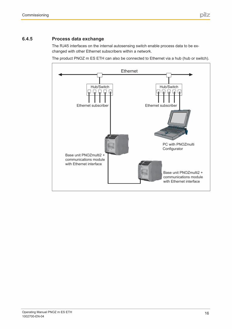
6.4.5 Process data exchangeThe RJ45 interfaces on the internal autosensing switch enable process data to be exchanged with other Ethernet subscribers within a network.
The product PNOZ m ES ETH can also be connected to Ethernet via a hub (hub or switch).
Base unit PNOZmulti2 +
communications module
with Ethernet interface
Ethernet subscriber Ethernet subscriber
Base unit PNOZmulti2 +
communications module
with Ethernet interface
PC with PNOZmulti
Configurator

Operation
Operating Manual PNOZ m ES ETH1002700EN04
17
7 OperationWhen the supply voltage is switched on, the PNOZmulti safety system copies the configuration from the chip card.
The LEDs "POWER","DIAG", "FAULT", "IFAULT" and "OFAULT" light up on the base unit.
The safety system PNOZmulti is ready for operation when the "POWER" and "RUN" LEDson the base unit and the "POWER" LED on the PNOZ m ES ETH are lit continuously.
7.1 MessagesLegend:
LED on
LED flashes
LED off
LED LED status Meaning
Power No supply voltage
Green Supply voltage is present
L/A 1 ( Link / Act 1 ) No network connection at X1 / No data traffic at X1
Green Network connection present at X1 / Data traffic presentat X1
L/A 2 ( Link / Act 2 ) No network connection at X2 / No data traffic at X2
Green Network connection present at X2 / Data traffic presentat X2
Fault Red Internal fault
Red No connection to base unit
DHCP Yellow The unit could not be assigned an IP address by theDHCP Server.
Yellow The unit is waiting for the DHCP Server to assign an IPaddress
Operation
Operating Manual PNOZ m ES ETH1002700EN04
18
7.2 Reset Ethernet connection settingsThe Ethernet connection settings of the base unit can be configured in the PNOZmulti Configurator.
You can reset the base unit's Ethernet connection settings to the default settings.
Proceed as follows:
} Switch off the supply voltage
} Remove the chip card
} Restart the base unit without the chip card inserted.
The Ethernet connection settings are now reset to the default settings.
Tecnical details
Operating Manual PNOZ m ES ETH1002700EN04
19
8 Tecnical details
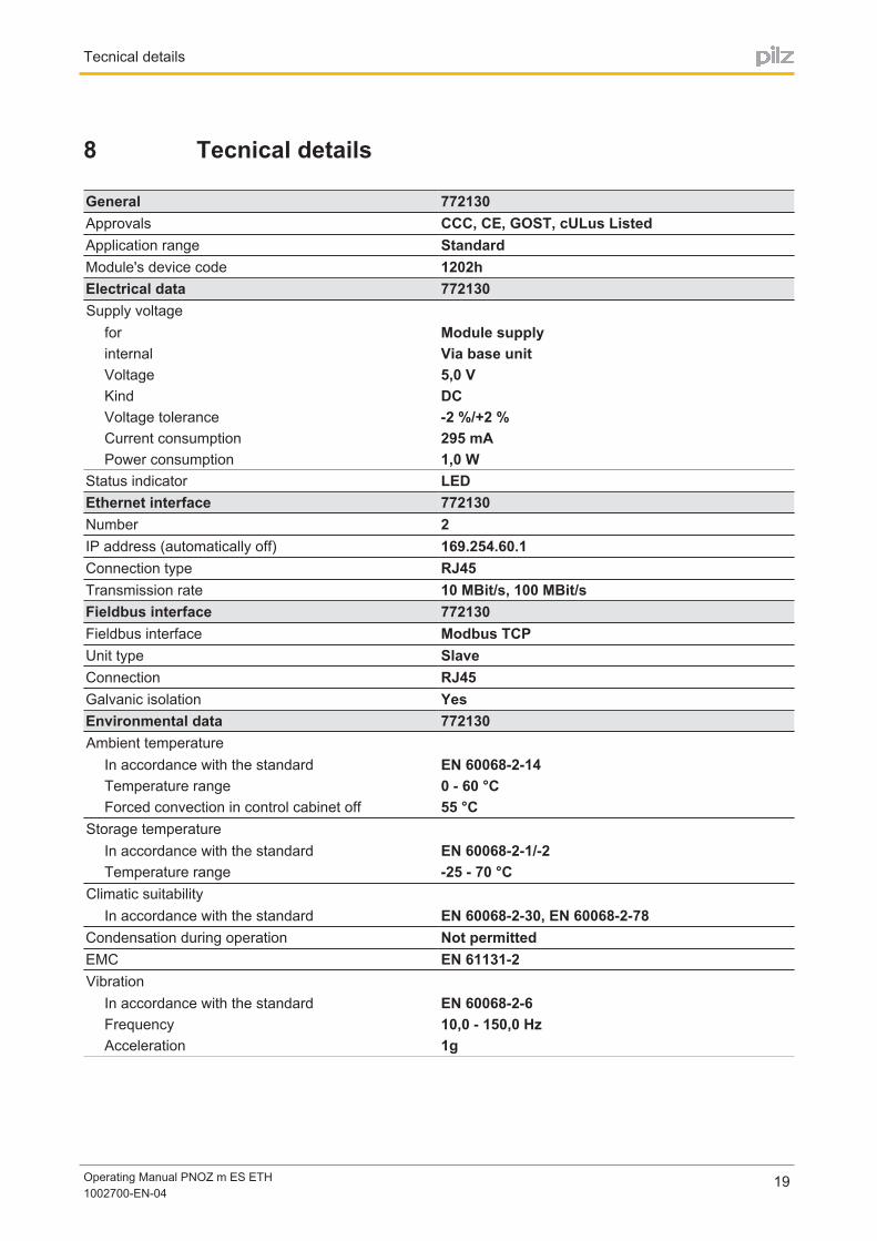
General 772130Approvals CCC, CE, GOST, cULus ListedApplication range StandardModule's device code 1202hElectrical data 772130Supply voltage
for Module supplyinternal Via base unitVoltage 5,0 VKind DCVoltage tolerance 2 %/+2 %Current consumption 295 mAPower consumption 1,0 W
Status indicator LEDEthernet interface 772130Number 2IP address (automatically off) 169.254.60.1Connection type RJ45Transmission rate 10 MBit/s, 100 MBit/sFieldbus interface 772130Fieldbus interface Modbus TCPUnit type SlaveConnection RJ45Galvanic isolation YesEnvironmental data 772130Ambient temperature
In accordance with the standard EN 60068214Temperature range 0 60 °CForced convection in control cabinet off 55 °C
Storage temperatureIn accordance with the standard EN 6006821/2Temperature range 25 70 °C
Climatic suitabilityIn accordance with the standard EN 60068230, EN 60068278
Condensation during operation Not permittedEMC EN 611312Vibration
In accordance with the standard EN 6006826Frequency 10,0 150,0 HzAcceleration 1g
Tecnical details
Operating Manual PNOZ m ES ETH1002700EN04
20
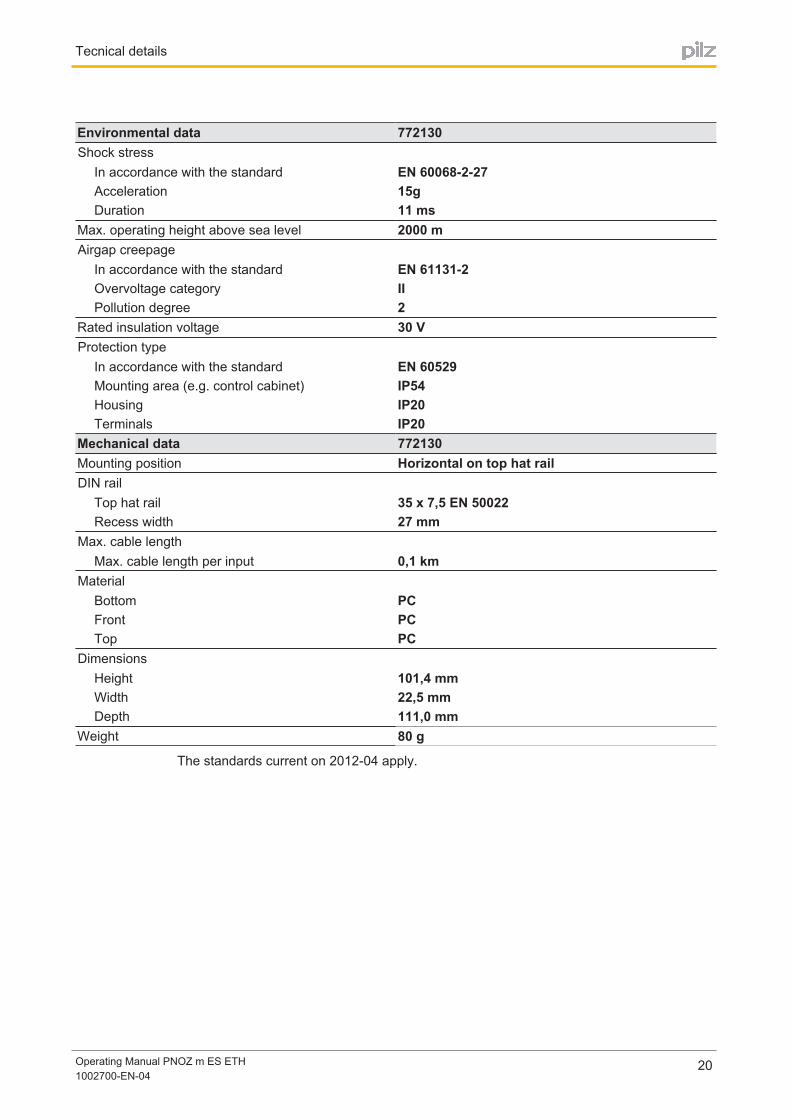
Environmental data 772130Shock stress
In accordance with the standard EN 60068227Acceleration 15gDuration 11 ms
Max. operating height above sea level 2000 mAirgap creepage
In accordance with the standard EN 611312Overvoltage category IIPollution degree 2
Rated insulation voltage 30 VProtection type
In accordance with the standard EN 60529Mounting area (e.g. control cabinet) IP54Housing IP20Terminals IP20
Mechanical data 772130Mounting position Horizontal on top hat railDIN rail
Top hat rail 35 x 7,5 EN 50022Recess width 27 mm
Max. cable lengthMax. cable length per input 0,1 km
MaterialBottom PCFront PCTop PC
DimensionsHeight 101,4 mmWidth 22,5 mmDepth 111,0 mm
Weight 80 g
The standards current on 201204 apply.
Order reference
Operating Manual PNOZ m ES ETH1002700EN04
21
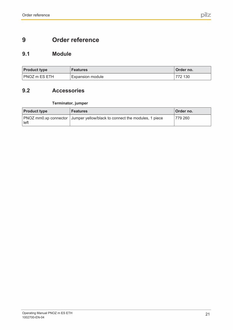
9 Order reference
9.1 Module
Product type Features Order no.
PNOZ m ES ETH Expansion module 772 130
9.2 Accessories
Terminator, jumper
Product type Features Order no.
PNOZ mm0.xp connectorleft
Jumper yellow/black to connect the modules, 1 piece 779 260

...
Sachnum
mer
Printe
d in G
erm
an
y
©
Pilz
Gm
bH
& C
o.
KG
, 2011
+49 711 [email protected]
Pilz GmbH & Co. KGFelix-Wankel-Straße 273760 Ostfildern, GermanyTelephone: +49 711 3409-0Telefax: +49 711 3409-133E-Mail: [email protected]: www.pilz.com
Technical supportIn many countries we are represented by our subsidiaries and sales partners.
Please refer to our homepage for further details or contact our headquarters.
Ind
ura
NE
T p
®, P
ilz®, P
IT®, P
MC
pro
teg
o®, P
MI®
, P
NO
Z®, P
rim
o®, P
SE
N®, P
SS
®, P
VIS
®, S
afe
tyB
US
p®, S
afe
tyE
YE
®, S
afe
tyN
ET
p®, th
e s
pirit o
f safe
ty® a
re r
eg
iste
red
and
pro
tecte
d t
rad
em
ark
s
of
Pilz
Gm
bH
& C
o. K
G in s
om
e c
ountr
ies. W
e w
ould
po
int
out
that
pro
duct
featu
res m
ay v
ary
fro
m t
he d
eta
ils s
tate
d in t
his
do
cum
ent,
dep
end
ing
on t
he s
tatu
s a
t th
e t
ime o
f p
ub
licatio
n a
nd
the s
co
pe
of
the e
qu
ipm
ent.
We a
ccep
t no
resp
onsib
ility
fo
r th
e v
alid
ity,
accura
cy a
nd
entire
ty o
f th
e t
ext
and
gra
phic
s p
resente
d in t
his
info
rmatio
n. P
lease c
onta
ct
our
Technic
al S
up
po
rt if
yo
u h
ave a
ny q
uestio
ns.
1002700EN04, 201403 Printed in Germany
© Pilz GmbH
& Co. KG, 2011
Back cover