Embed Size (px)
Citation preview

Plastic Deformation in Crystalline Materials
Kamyar Davoudi ���
Fall 2015���
1
Lecture 1: Overview

2
Solids:
Crystalline
amorphous
Single Crystalline
Poly Crystalline
Structure of Solids
Quasi-crystalline* (ordered but not periodic; lacks translational symmetry)

3
• Solids are often crystalline.• A solid may be found in a crystalline or amorphous
form. Each may have its own applications���For example:
• Crystalline silicon (Si) are used in ICs.• Amorphous silicon (Si) are sometimes used in Li-ion
batteries and solar cells• Amorphous metals are often called metallic glasses• It is really hard to make some metals amorphous (e.g.
Ag)
Crystalline vs Amorphous Solids

Let’s start with some ������elementary diagrams ������we saw in elementary mechanics of materials and ask ������
Some questions4

5
Low carbon steel Aluminum Alloy
Stress-Strain Curve
Stress-Strain Curve of a metal under uniaxial loading: ��� One of the first things we learned in mechanics of materials
• Why do materials become plastic? What is the mechanism of plastic deformation?
• Why stress-strain curves of different materials are different?
• How can we model strain hardening (= work hardening)?
Questions:[Beer & Johnston et al, mechanics of materials]

6
Stress-Strain Curve – Loading and Unloading
Again what we saw in the first chapters of mechanics of materials
[Beer & Johnston et al, mechanics of materials]

Bauschinger Effect
[Xiang, Vlassak, Acta Mater, 2006]
7
Question:
What causes the Bauschinger effect?

Effects of Orientation & Loading Rates���
8
Nom
inal
She
ar S
tres
s [k
g/m
m2 ]
Nominal Shear [%]
Nominal stress strain curves (without correction for area changes and orientation changes) for 99.99% pure Al, at two tensile strain rates: three single crsytals of different orientations and one polycrystal of a grain size of 0.2 mm. After Kocks et al., Work Hardening, 1968
Questions:
• How does the orientation affect the deformation?
• What is the difference between deformation of single crystal and polycrystal?
• How does the loading rate affect the deformation?������

Effects of Temperature
9
Question:How does the temperature affect the hardening rate?
Nom
inal
Str
ess
[kg
/mm
2 ]
Strain [%]

Creep
10
strain vs time (in tension) strain vs time (in compression)
σ
t
Three stages: (I) primary creep regime (II) quasi-steady-state regime (III) tertiary creep regime
ε
t
ε
t
Question: What is the explanation for each regime?

Size Dependent Behavior: Experiment
11
Pure Ni microsamples having a <134> orientation (A) stress-strain curves for samples with different diameters (B) SEM image at 4% strain (diameter 20 µm) (C) SEM image at 19% strain (diameter 5 µm) [Uchic et al., Science, 2008]

Another Experiment: Bulge Test
12
• Applied pressure p and membrane deflection h are measured• Average stress and strain are determined using following (or more sophisticated)
expressions
σ=
pa2
2hδ, ε= ε0 +
2δ2
3a2
: residual strain in the film ε0
before pressure is applied after pressure is applied
[Xiang, Vlassak, Scripta Mater., 2005]
σ"60o
h σ"
Plane Strain Model:

Bulge Test - II
13
σ"60o h
σ"
Effect of Film Thickness: Effect of Passivation:
Cu Films with both surfaces passivated of different film thicknesses
Cu film of thickness h = 340 nm
[Xiang, Vlassak, Acta Mater., 2006]

Importance of Study of Mechanical Behavior of Materials at Small Scales
14
Detailed and quantitative understanding of size effect is essential for a reliable design
Many of failure mechanisms are stress-driven
It is critical to know the strength of a component in a device and hence the level of stress it can support
http://gtresearchnews.gatech.edu/newsrelease/mems-cad.htm

1980s Small Scale Devices
Experiments exhibited size dependence1990s
1950s Hall – Petch effectBrenner’s paper on whiskersConference in NY
1924 First Report by G.I. Taylor
15
Size Effect

Continuum Mechanics Approach for Size Effect
16
In classical approach:
In nonlocal approach
This requires introduction of one or more length parameters into the constitutive equation
There is no strain gradient theory that can be applied to all experiments
!σ= function( !ε, T,…)
!σ= function( !ε,∇ !ε, ∇2 !ε, …,T,…)
f(σij ,εijp ,k)= F(σij ,εij
p )−k2(εpe )= 0

“it is sometimes said that the turbulent flow of fluids is the most difficult remaining problem in classical physics. Not so. Work hardening is worse.” (A.H. Cottrell, 2002)
2 4 6 8 10
10
20
30
40
60
strain [%]
stre
ss
[MPa
]
(Kocks, Trans ASME, 1970)
17

One Solution
• We should consider why and how crystals
deform plastically.
18

Ideal Shear Strength
19
Consider a single crystal
τ = τmax sin 2πx
b
If τ < τmax : shear strain is elastic and will disappear when the stress is released.
For very low value of γ = x / a : τ = G γ
Therefore:
dτdγ⎛
⎝⎜⎜⎜⎜
⎞
⎠⎟⎟⎟⎟⎟
x→0
= G
τmax =
Gb2πa≈
G2π
More accurate calculations showed that τmax= G/30 which is still >>measured shear strength

Ideal shear strength >> measured shear strength
81 years ago : Dislocations
Why materials become plastic
G.I. Taylor Egon Orowan Michael Polyani
20
Work hardening was the first problem that was considered
16 volumes of “Dislocations in Solids”

1953A.H. Cottrell: [Work hardening] was the first problem to be attempted by dislocation theory and may be the last to be solved
2009 L. Kubin: There is presently no generally accepted theory explaining how and why organized dislocation microstructures emerge during plastic flow
2003 U.F. Kocks & H. Mecking Work hardening is as hopeless as ever
21

Work hardening was the first problem that was considered
G.I. Taylor F. Nabarro
Frederick C Frank
Nevil Mott* Rudolf Peierls* William Schockley*
Alan Cottrell U Fred KocksJ. Friedel T Mura H. Mecking
John Hirth Jens Lothe J. & J. Weertman
Ladislas Kubin 22
Egon Orowan
* Nobel Laurites

Work Hardening Modeling
• Collective motion of dislocations è Plastic Deformation
• Individual processes are well understood• Understanding overall effects is challenging without
computer modeling
some main processes into the model ��� à Discrete Dislocation Dynamics
23
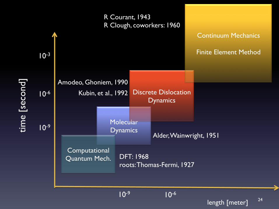
Molecular Dynamics
Discrete Dislocation Dynamics
Continuum Mechanics������
Finite Element Method
Computational Quantum Mech.
10-9 10-6
10-3
10-9
10-6
time
[sec
ond]
length [meter]
DFT: 1968���roots: Thomas-Fermi, 1927
Alder, Wainwright, 1951
R Courant, 1943R Clough, coworkers: 1960
Amodeo, Ghoniem, 1990
Kubin, et al., 1992
24