Embed Size (px)
Citation preview
Stockholm, January 2006
INVESTIGATION ON NITRIDING WITH ENPHASIS IN
PLASMA NITRIDING PROCESS, CURRENT
TECHNOLOGY AND EQUIPMENT:
Review Article
By
ANDRES BERNAL
Calle 29C#53-23 Phone: (57)- (4) - 265 8382
[email protected] Medellín - Colombia
MATERIALS PROCESSING
ROYAL INSTITUTE OF TECHNOLOGY - KTH
STOCKHOLM -100 44
SWEDEN
ABSTRACT
Nitriding is a case hardening thermo-chemical process used in many applications
today. A literature research was done in order to study the nitriding mechanism and
different nitriding methods used in industry. Gas, salt bath and plasma nitriding are
widely explained as well as their advantages and disadvantages. A special chapter is
dedicated to study how the plasma nitriding process works, the plasma technology
used for it and the physics behind it. Research has been done in the combination of
nitriding with different surface engineering processes in order to improve the
mechanical properties of components. A review of the different technologies that have
been developed in this field is also included in this paper. Three samples of Orvar
supreme (H13 type steel) were gas nitrided, nitrocarburized and plasma nitrided. The
different process parameters for each sample are presented in a table, the thickness of
the compound layer as well as the diffusion layer were measured and compared to
each other.
CONTENTS
1 NITRIDING.................................................................................................................1
1.1 Why Nitriding .........................................................................................................4
2 DIFFERENT NITRIDING METHODS........................................................................6
2.1 Gas Nitriding...........................................................................................................6
2.2 Salt Bath Nitriding ..................................................................................................9
2.3 Plasma Nitriding ...................................................................................................11
3 PROCESS TECHNOLOGY OF PLASMA NITRIDING...........................................17
3.1 Nitriding System with Enhanced Discharge ..........................................................18
3.2 Duplex Coatings ....................................................................................................19
3.3 Low-Pressure Nitriding Using a Microwave Discharge .........................................20
3.4 Continuous Duplex Process Using a Bipolar Pulsed Power Supply........................21
3.5 Active Screen Plasma Nitriding.............................................................................22
4 PLASMA TECHNOLOGY AND NITRIDING EQUIPMENT....................................23
4.1 The Importance of Collisions in Plasmas ...............................................................24
4.2 Type of Plasma Used in Plasma Nitriding: Glow Discharge ..................................27
4.3 Plasma Nitriding Equipment Used Today .............................................................28
5 NITRIDING EXPERIMENTS ON HOT-WORK TOOL STEEL................................33
5.1 Experiments Discussion.........................................................................................34
6 CONCLUSIONS.......................................................................................................35
7 REFERENCES.........................................................................................................37
1
1 NITRIDING
Nitriding is a case hardening heat treatment process which runs at temperatures
between 450 – 600 °C for steel. The aim of the process is to diffuse nitrogen into the
substrate surface to form nitrides in combination with different alloying elements of the
substrate and to form compound layers that have high wear resistance properties.
Since nitriding changes the chemical composition of the surface of the substrate and
the process is carried out at medium temperature, it is classified as a thermo chemical
process. Although many different materials can be nitrided with the aid of new nitriding
technologies, this paper will focus on nitriding of steel substrates.
At the temperature that the process is held, nitrogen diffusion occurs in the ferritic
phase of the steel, thus, no phase transformation occurs during cooling of the
substrate. This mechanism differs from traditional case hardening methods such as
carburizing. When carburizing, a phase transformation occurs when cooling the
substrate since the process is held at temperatures were the stable phase of the steel
is austenite. Here, the carbon content of the steel surface is increased and
subsequently quenched to transform the austenite into martensite which is the phase
that provides high hardness and the wear resistance.
Avoiding a phase transformation of the bulk during the nitriding process offers a big
advantage because it minimizes the distortions that arise from the normal carburizing
and quenching heat treatment processes. This is of big importance in costs structure
when processing components or tools that will have a post-heat-treatment machining
or finishing process. This topic will be further discussed later in this chapter.
According to Thelning [1], when studying nitriding we can make use of the iron-nitrogen
equilibrium diagram shown in figure 1.
2
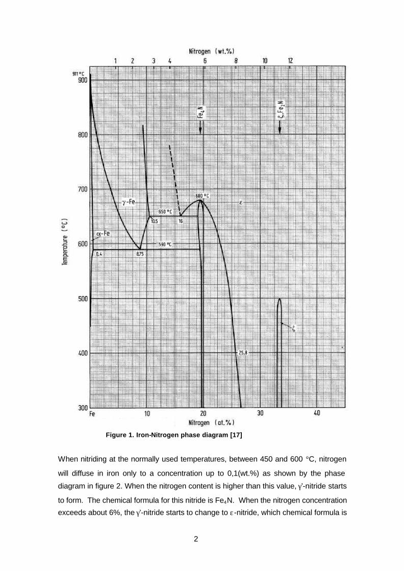
Figure 1. Iron-Nitrogen phase diagram [17]
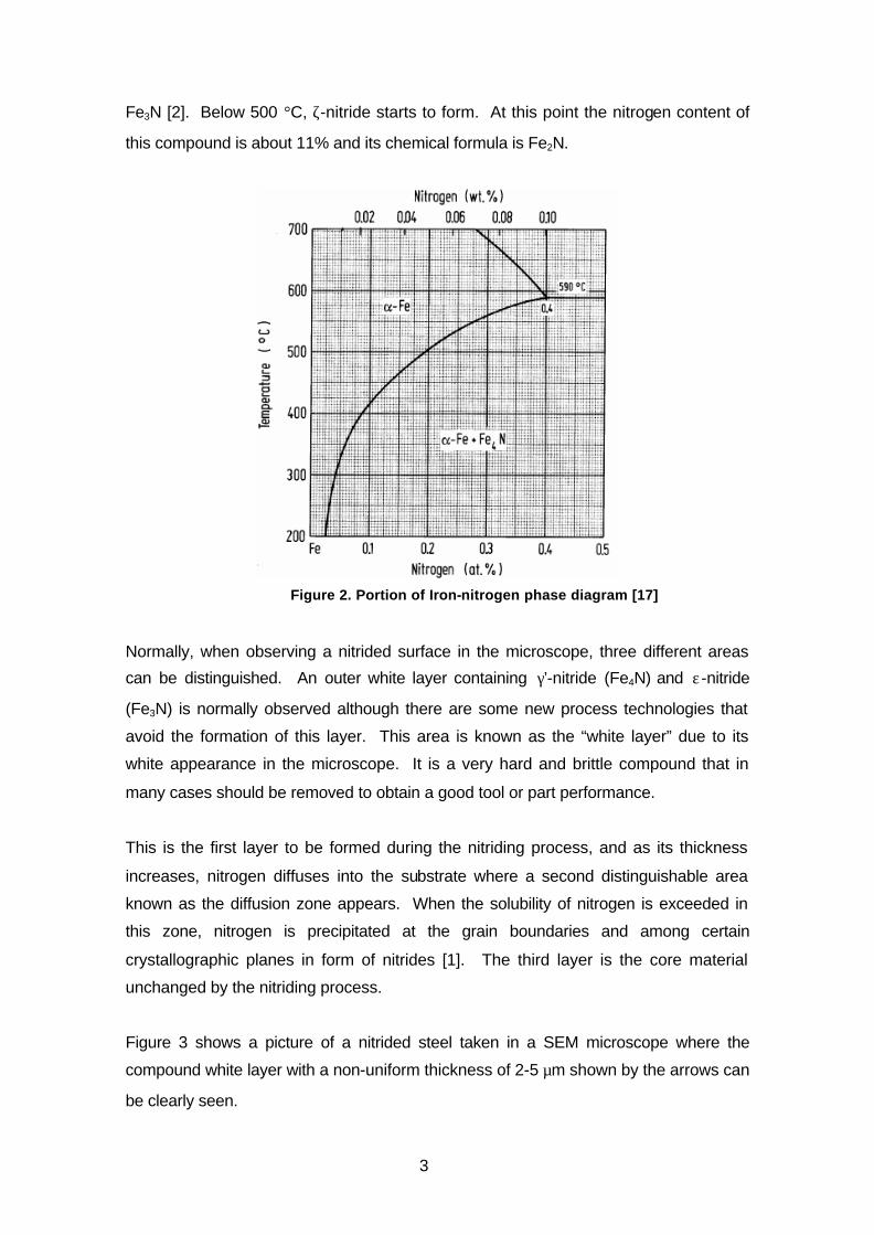
When nitriding at the normally used temperatures, between 450 and 600 °C, nitrogen
will diffuse in iron only to a concentration up to 0,1(wt.%) as shown by the phase
diagram in figure 2. When the nitrogen content is higher than this value, γ’-nitride starts
to form. The chemical formula for this nitride is Fe4N. When the nitrogen concentration
exceeds about 6%, the γ’-nitride starts to change to ε-nitride, which chemical formula is
3
Fe3N [2]. Below 500 °C, ζ-nitride starts to form. At this point the nitrogen content of
this compound is about 11% and its chemical formula is Fe2N.
Figure 2. Portion of Iron-nitrogen phase diagram [17]
Normally, when observing a nitrided surface in the microscope, three different areas
can be distinguished. An outer white layer containing γ’-nitride (Fe4N) and ε-nitride
(Fe3N) is normally observed although there are some new process technologies that
avoid the formation of this layer. This area is known as the “white layer” due to its
white appearance in the microscope. It is a very hard and brittle compound that in
many cases should be removed to obtain a good tool or part performance.
This is the first layer to be formed during the nitriding process, and as its thickness
increases, nitrogen diffuses into the substrate where a second distinguishable area
known as the diffusion zone appears. When the solubility of nitrogen is exceeded in
this zone, nitrogen is precipitated at the grain boundaries and among certain
crystallographic planes in form of nitrides [1]. The third layer is the core material
unchanged by the nitriding process.
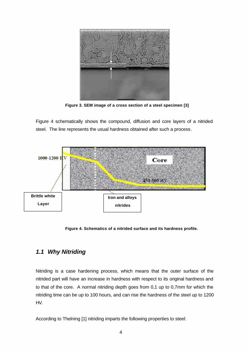
Figure 3 shows a picture of a nitrided steel taken in a SEM microscope where the
compound white layer with a non-uniform thickness of 2-5 µm shown by the arrows can
be clearly seen.
4
Figure 3. SEM image of a cross section of a steel specimen [3]
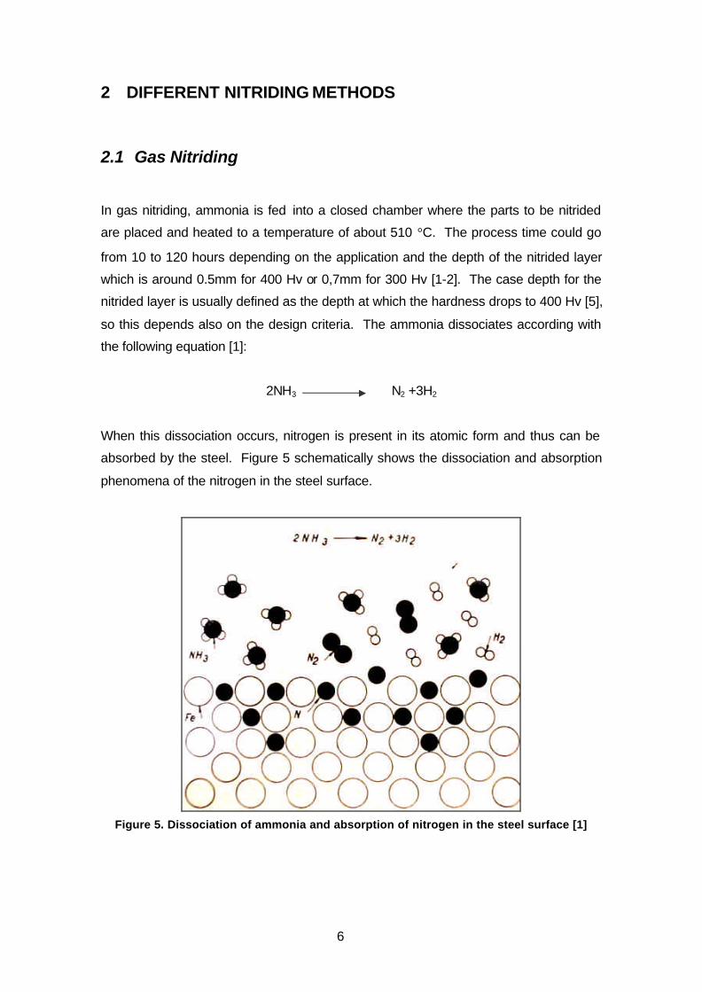
Figure 4 schematically shows the compound, diffusion and core layers of a nitrided
steel. The line represents the usual hardness obtained after such a process.
Figure 4. Schematics of a nitrided surface and its hardness profile.
1.1 Why Nitriding
Nitriding is a case hardening process, which means that the outer surface of the
nitrided part will have an increase in hardness with respect to its original hardness and
to that of the core. A normal nitriding depth goes from 0,1 up to 0,7mm for which the
nitriding time can be up to 100 hours, and can rise the hardness of the steel up to 1200
HV.
According to Thelning [1] nitriding imparts the following properties to steel:
Brittle white
Layer
Iron and alloys
nitrides

5
- High surface hardness and wear strength, together with reduced risk of galling.
- High resistance to tempering and high-temperature hardness.
- High fatigue strength and low fatigue notch sensitivity.
- Improved corrosion resistance for non stainless steel.
- High dimensional stability compared to other heat treatment processes.
Even though nitriding produces high surface hardness, the process is not always the
best choice for abrasive wear applications. High point loads can chip the nitrided layer
away. In fact, nitriding finds its best use for adhesive wear applications. The outer
compound layer reduces friction and improves the corrosion resistance of the steel,
except for stainless steels in the later case. Because of its high hardness and
resistance to tempering, nitriding can be applied to elements that will work on high
temperatures of approximately 600 °C [5].
A very important advantage of nitriding over other case hardening processes is the low
process temperature. While carburizing is held at high temperatures, around 970 °C,
where the diffusion process of the elements takes place in the austenite phase of the
steel, nitriding takes place in the ferrite phase, allowing some steel grades to maintain
most of their prior mechanical properties after the process. This is an advantage since
in most cases it is useful to heat treat the bulk before nitriding in order to be able to
have a higher core hardness. This high hardness of the core gives the hollow nitrided
layer a good mechanical support, thus preventing it from cracking due to elastic
deformation. If the process was held at high temperatures, the steel’s core would be
tempered back to its original annealed hardness.
Today, more and more efforts are being made to be able to lower the nitriding
temperatures and in this way to expand the number of materials on which this process
can be applied. Plasma technologies and its applications are being studied to be able
to reduce the nitriding temperature as much as possible.
In the following section, we will take a brief look at the different nitriding processes.
After that, plasma nitriding and its most recent developments will be discussed more in
detail.
6
2 DIFFERENT NITRIDING METHODS
2.1 Gas Nitriding
In gas nitriding, ammonia is fed into a closed chamber where the parts to be nitrided
are placed and heated to a temperature of about 510 °C. The process time could go
from 10 to 120 hours depending on the application and the depth of the nitrided layer
which is around 0.5mm for 400 Hv or 0,7mm for 300 Hv [1-2]. The case depth for the
nitrided layer is usually defined as the depth at which the hardness drops to 400 Hv [5],
so this depends also on the design criteria. The ammonia dissociates according with
the following equation [1]:
2NH3 N2 +3H2
When this dissociation occurs, nitrogen is present in its atomic form and thus can be
absorbed by the steel. Figure 5 schematically shows the dissociation and absorption
phenomena of the nitrogen in the steel surface.
Figure 5. Dissociation of ammonia and absorption of nitrogen in the steel surface [1]
7
The driving force for nitriding is the nitrogen potential in the gaseous atmosphere,
which is expressed by [7]:
2/32
3
H
NH
p
pNp =
Thus, the nitrogen potential describes the nitriding capacity of the atmosphere. By
controlling this, the formation of different structures in the material can be controlled. In
general, higher potential create higher surface concentration of nitrogen and higher
concentration gradients towards the core material. Lower nitrogen potential allows the
development of nitrided surfaces with the formation of very thin brittle compound layer
or “white layer” [7] for gas nitriding and its complete absence in plasma nitriding.
Nitrogen is one of the atoms that can be interstitially dissolved in iron, thus the
possibility of having a diffusion process from the gas inside the steel surface. In this
process quenching is not required after processing since the hardening mechanism is
not the formation of martensite, as it is when carburizing, but the formation of hard
finely dispersed nitrides and carbonitrides which distort the ferrite lattice [1].
These compounds, known as nitrides, can be formed with different alloying elements
besides iron, among them Al, Cr, Mo, V and W. These elements are commonly known
as good nitride formers because they form stable nitrides at the nitriding temperatures.
Commercially, these alloying elements are found in many grades of tool steel and
some in machinery steel grades. Molybdenum for example, besides its contribution
as a nitride former, reduces the brittleness of the nitrided layer at nitriding
temperatures. It is important, on the other hand, to be aware that the depth of the
nitrided layer reduces as the amount of alloying elements increase since they slow
down the diffusion process of nitrogen into the matrix. Alloying elements as nickel,
copper, silicon and manganese, have little or no effect in the nitriding process [2].
On the other hand, it has been shown by the authors of [4], that the nickel content has
an influence in the distribution of the nitrides and therefore affects the properties of the
nitrided layer. Steels alloyed with nickel were found to propitiate a fine size and an
even distribution of the nitrides and reduce the brittleness of the nitrided layer.
8
Although all steels are capable of forming iron nitrides when exposed to atomic
nitrogen, the nitriding is enhanced by nitride forming elements as the ones discussed
above.
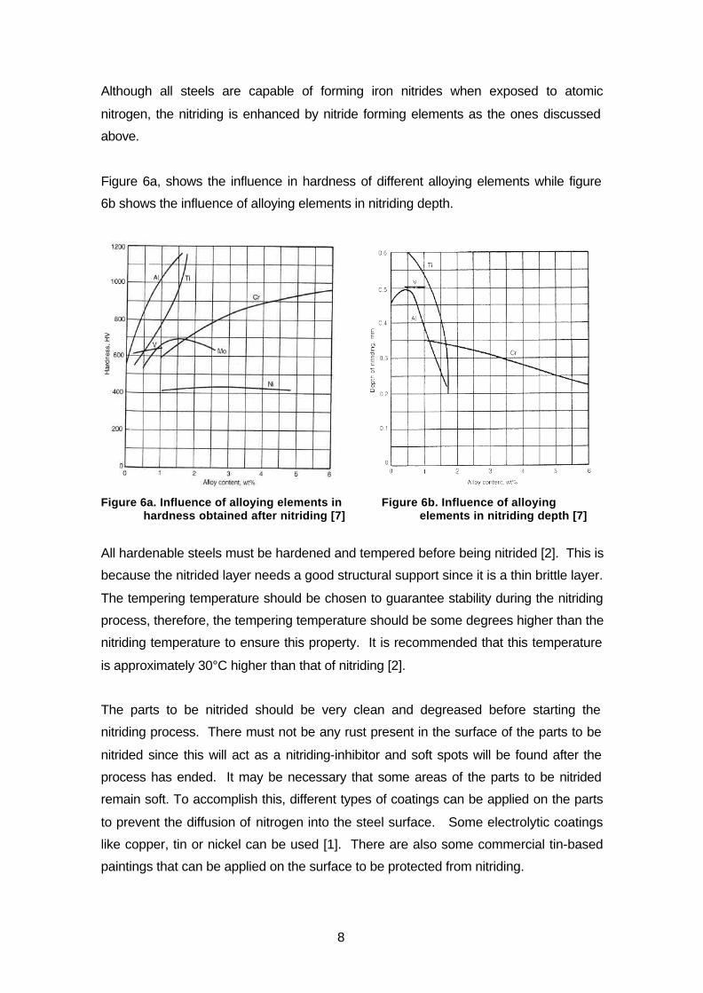
Figure 6a, shows the influence in hardness of different alloying elements while figure
6b shows the influence of alloying elements in nitriding depth.
Figure 6a. Influence of alloying elements in
hardness obtained after nitriding [7] Figure 6b. Influence of alloying
elements in nitriding depth [7]
All hardenable steels must be hardened and tempered before being nitrided [2]. This is
because the nitrided layer needs a good structural support since it is a thin brittle layer.
The tempering temperature should be chosen to guarantee stability during the nitriding
process, therefore, the tempering temperature should be some degrees higher than the
nitriding temperature to ensure this property. It is recommended that this temperature
is approximately 30°C higher than that of nitriding [2].
The parts to be nitrided should be very clean and degreased before starting the
nitriding process. There must not be any rust present in the surface of the parts to be
nitrided since this will act as a nitriding-inhibitor and soft spots will be found after the
process has ended. It may be necessary that some areas of the parts to be nitrided
remain soft. To accomplish this, different types of coatings can be applied on the parts
to prevent the diffusion of nitrogen into the steel surface. Some electrolytic coatings
like copper, tin or nickel can be used [1]. There are also some commercial tin-based
paintings that can be applied on the surface to be protected from nitriding.
9
By varying the process parameters and controlling different process stages, a reduction
of the so-called white layer and a deeper penetration of the diffusion layer can be
obtained. The parameters to vary are: Temperature, process duration and the degree
of dissociation of the ammonia gas in the chamber at different stages of the same
process [2].
Gas nitriding is not used for steels that have a high content of chromium like stainless
steels. The reason is that these type of steels, due to their chemical composition, form
a chromium oxide layer on the surface of the steel that acts as a corrosion protecting
film that has to be broken to allow the nitrogen diffusion into de substrate. This film,
can be only broken by plasma nitriding which will be discussed later [5].
2.2 Salt Bath Nitriding
The process is called salt bath nitriding because the parts to be nitrided are immersed
into a salt bath containing molten salt combinations. The salt mixtures originally had 60
– 70% by weight NaCN and 30-40% KCN [1]. There is in addition, a few percent of
carbonates Na2CO3 and cyanates NaCNO. The process relies on the decomposition of
cyanade to cyanate.
At operation, a desired level of cyanate should be 45%. This is accomplished by aging
the bath at a temperature of approximately 570 °C and for around 12 hours. It is
important to keep this level of cyanates along the whole bath to avoid differences of
hardness and nitrided layer thickness in the steel parts, thus, to do this, air is injected
into the bath to control the cyanate level [1].
Another problem that may easily arise, is the dissolution of the iron crucible in the bath.
This leads to oxidation and pitting of the steel charge. To overcome this problem the
crucibles of the salt baths today are made of titanium. The normal temperatures for
this process are between 550 – 570 °C and a maximum average process time of about
2 hours and up to maximum 4 hours. During immersion time the salt bath gives off
carbon and nitrogen according to the following expressions[1]:
4NaCNO 2NaCN + Na2CO3 + CO + 2N
3Fe + 2CO Fe3C + CO2
10
The process using this type of salts was developed by DEGUSSA and is called the
Tufftride process (Teniferbehandlung in German).
A different variation of the process is called the “Sulfinuz Treatment” [1]. In this
process sodium sulphide (Na2S) is also a component of the salt, which will liberate
sulphur that will be included in the nitrided layer enhancing the antifriction properties of
the outer compound layer.
After any of these processes, quenching in warm water will give a better result. This
will create a supersaturated solid solution of nitrogen in α-iron and thus increase the
fatigue resistance of the part. On the other hand, this operation reduces the
toughness of the nitrided layer [1] which should also be considered.
Salt baths became very popular because the process led to an outer surface
compound layer of γ’-nitride (Fe4N) and ε-nitride (Fe3N) which are not as brittle as ζ-
nitride (Fe2N) and are used to enhance the wear resistance, the friction properties and
the corrosion resistance of the steel surface. The formation of these layers is due to
the reaction between oxygen-saturated-cyanates which are active compounds which
were formed by aeration of the bath which oxidized the cyanides, and the steel surface
[6].
Although very beneficial, for years salt baths have been used with some problems, i.e.
it was hard to control the chemical composition of the salt and had big environmental
problems such as complicated regulation for disposal of waste salts and the disposal of
rinse water which is also environmentally hazardous. These complications made the
development of the baths to slow down and in many cases be replaced by gas nitriding
[6].
Due to this, there has been a necessity for developing a novel salt bath composition
that having the same nitriding capabilities was environmentally friendly. Cyanate-base
baths were developed. In this type of baths, the environmental problem was solved
since the disposal process and control of the salt reactivity with the help of a developed
generator was much more easier than that with the cyanade baths. On the other hand,
it took some time for the process to be fully developed and go into industrial use since
the chemical reactivity of the bath was difficult to control [6].
11
Salt baths have a great advantage because by controlling the composition of the salt,
the chemical reactivity of the bath can be controlled, thus leading to a decrease of the
process temperature. Lowering the process temperature is of high importance since it
means less distortion of the treated part and gives the ability for processing a broader
band of steel grades without diminishing their mechanical properties.
With the new cyanate-based baths, the chemical reactivity can be controlled to obtain
process temperatures as low as 480 °C and still avoid all the environmental problems
that the cyanide baths presented [6].
Salt bath nitriding has shown to be a faster process than gas nitriding due to better
heat transfer properties and high reactivity of the bath. As a guide, it could be said that
10 hours of gas nitriding correspond to 4 hours of processing in a salt bath
On the other hand, conventional salt bath nitriding times are restricted to maximum 4
hours due to the formation of pores in the white layer. Often, a greater depth of
nitriding is required than that obtained during this time, which becomes a limiting
parameter for this process [1].
2.3 Plasma Nitriding
Plasma nitriding, also known as ion nitriding or glow discharge nitriding, is a gas
nitriding process enhanced by a plasma discharge on the part to be nitrided. The
plasma is gas that when exposed to an electrical potential is ionized and glows. The
parts to be nitrided are connected as a cathode and the furnace walls are the anode.
They are supplied with a potential between 0.3 and 1KV [8].
Particles are accelerated and hit the cathode (work piece) transferring all their kinetic
energy and heating it. For gas particles to have enough kinetic energy to transfer, they
need to have a considerable large mean free path and in this way gain speed for
collision with the substrate before colliding with another gas particle. This is why this
process and mostly all plasma processes work under vacuum as a measure to
increase the mean free path of the accelerated particles. The pressure used for plasma
nitriding is normally between 100 – 1000Pa [8]. Other authors as in ref [7] suggest a
narrower range between 50 – 500Pa. This pressure is considered as a rough vacuum
since there are other processes that use much higher vacuum values.
12
The chemical reaction when ammonia dissociated was explained in the preceding
section. In the case of plasma nitriding, the process gases are introduced separately.
One combination that is often used is Nitrogen + Hydrogen. Argon is also used in the
initial stages as a plasma sputtering gas for surface cleaning of the substrate to be
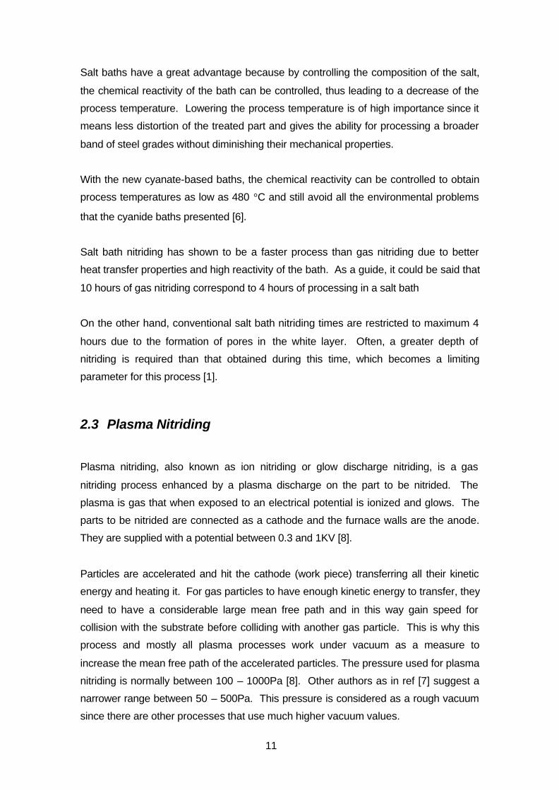
nitrided. This will be explained later on. Figure 7 shows Koebel’s model for the glow
discharge ion nitriding mechanism. The voltage drop occurs in what is called the
plasma sheath which is a positive charged area where ions are accelerated towards
the cathode and have their highest kinetic energies.
Figure 7. Koebel’s model of the plasma nitriding mechanism [7]
During ion nitriding three reactions will occur at the surface of the material being
treated. In the first reaction, iron and other contaminants are removed from the surface
of the work by an action known as sputtering or by a reducing reaction with hydrogen.
The impact of hydrogen or argon ions bombarding the work surface dislodges the
contaminant that will be extracted by the vacuum system. The removal of these
contaminants allows the diffusion of nitrogen into the surface [7].
During the second reaction, and as a result of the impact of the sputtered ion atoms,
case formation begins at the work surface of iron nitrides [7].
Sputtered Fe + N = FeN
13
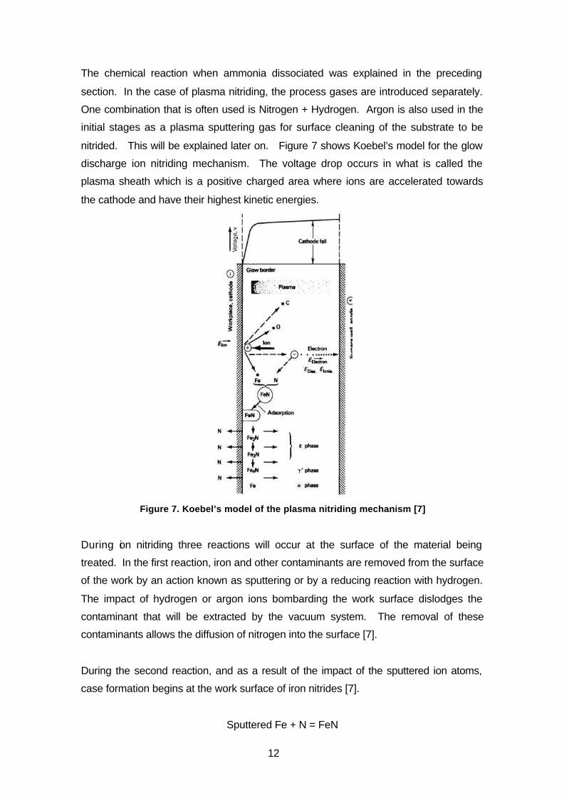
During the third reaction, a breakdown of the FeN begins under the continuous
sputtering from the plasma. This one causes the instability of the FeN which begins to
break down into the ε phase followed by the γ’ phase and a iron-nitrogen compound
zone [7]. This process is shown in figure 7 and explained by the following equations
[7].
2FeN Fe2N + N
3Fe2N 2Fe3N + N (ε-phase)
4Fe3N 3Fe4N + N (γ’ -phase)
Fe4N 4Fe + N (Iron/nitrogen compound zone)
Figure 8 shows a drawing of the process of formation of the compound zone during
nitriding.
Figure 8. Mechanism of formation of the compound zone [7]
In plasma, accelerated electrons collide with the nitrogen particles. At low electron
energies these collisions are elastic but as we increase the electron’s energy, as for
glow discharge plasmas, these collisions become inelastic. These inelastic collisions
with gas molecules or atoms result in their excitation. When exited, the molecule can
spontaneously undergo one of the following processes: (1) electron relaxation, back to
the ground state, (2) dissociation, or (3) ionization [9]. These phenomena will be
explained later but this is the basic phenomenon by which a plasma can enhance the
nitriding process by electron impacts with the gas molecules to create ions, free radical

14
and exited-sate molecules that will contribute to the surface reaction and nitrogen
diffusion.
Sputtering of the part to be nitrided is the other big advantage of plasma nitriding since
with this process the parts are atomically cleaned and the impact energy is used to not
only heat the part but also for surface cleaning and activation.
As the author of reference [10] shows, “Ricard et al, showed that for steel nitriding, the
N2+, the vibrational N2 and the N neutral species are most relevant.” But not all
vibrational N2 have enough vibrational energy to contribute to the nitriding process by
surface reaction according to a model suggested by Marchand et al [10]. Optimal
nitriding was obtained when the vibration level is V=46, where the molecular species
are thought to exist as atomic nitrogen [10]. This lead to the conclusion that a
minimum vibration level has to exist for the exited nitrogen molecules to contribute with
the nitriding of the surface.
Hydrogen plays an important role, both in the initial stage when cleaning the surface
and in the second stage when the nitrogen diffusion process takes place. In the initial
stage it acts as a reducing agent for the oxides present in the surface, thus cleaning it
and preparing it so the oxides do not block the diffusion of nitrogen. In the second
stage, hydrogen not only acts as a reducing agent, but also influences and regulates
the composition of the diffusion zone [7] by diluting nitrogen and lowering its potential in
the chamber’s atmosphere.
Even though there is no presence of oxygen because of the vacuum used during the
process, some decarburization might result from the reaction that takes place between
carbon atoms from the steel and active hydrogen species from the plasma to form CH3
species. This decarburization might be beneficial since taking away the carbon from
the steel surfaces enhances the diffusion of nitrogen inside the steel [12]. If some
oxygen is present in the chamber, its presence enhances decarburization by the
formation of CO2, however, for higher contents of O2 (above 3%), an oxide layer is first
formed that prevents the transport of carbon from the core to the steel surface and
partially stops the decarburization process [12].
Argon is also used in the first stage of the plasma nitriding process as a cleaning agent.
This is because argon is a heavier gas than nitrogen or hydrogen and therefore, when
Ar ions are accelerated, their kinetic energies are higher, which enhances the cleaning

15
when colliding with the substrate. Special attention has to be paid to the gas ratios
since etching of the surface of the substrate can be produced by the effect of argon, so
a ration of 95%H2 and 5% Ar and up to a maximum of 90%H2 and 10% Ar is normally
used [7].
2.3.1 Plasma Nitriding Advantages
Plasma nitriding is the latest developed nitriding technology, although its commercial
used was hindered for the first 50 years since its invention, new advances have
lowered the equipment cost and allow the technology to spread in an industrial level.
Some advantages of the process are listed by Pye [7] and are:
- Environmentally friendly gases: Different from gas and salt bath nitriding, which
produce toxic gases, plasma nitriding uses as process gases, nitrogen, hydrogen
and argon mainly, which are not harmful for people or the environment.
- No fire risk: Even though hydrogen my be dangerous, in the case of plasma
nitriding there is no risk of fire due to the vacuum used in the chamber which lowers
the oxygen level to such a point as to entirely reducing the risk.
- Shorter cycle times: The plasma properties enhance the deposition rate of nitrogen
inside the steel surface due to ion bombardment and to the presence of highly
active species. The lower heating time required also shortens the cycle time in
some cases.
- Automation: Low operator involvement reduces the risk of problems presented
during production, enhances the reliability and allows for process repeatability at a
metallurgical level.
- Low process gas consumption: This together with low energy consumption, results
in low operating costs.
- Ability to treat most steels: As was earlier explained, plasma nitriding allows the
nitriding of aluminum and stainless steel while other conventional processes do not.
- Ease of selective nitriding: Plasma nitriding allow for selective nitriding, i.e. to
nitride only selected areas of the same part.
- Low decarburization: When working under vacuum, low amount of oxygen is
present in the process chamber. This avoids the reaction of carbon with oxygen
and the decarburization of the steel surface.
- Low-maintenance equipment and very low operation cost are other advantages this
process presents.

16
2.3.2 Plasma Nitriding Disadvantages
Plasma processing technology has been developed intensively in the last 20 years.
This technology allows for many different materials processes from welding, to plasma
diffusion processes to coatings. Many different alternatives of this technology are
available yet not all are commercialized. The main reason for this, is the equipment
cost in the market that makes it not economically viable for many industrial
applications. The initial equipment cost, thus becomes one of the greatest
disadvantages of the plasma nitriding process against salt bath or conventional gas
nitriding process.
Another disadvantage of the process is the hollow cathode effect. Hollow cathode is
an area of low vacuum pressure where the plasma glow seam does not follow the
contour of the part being treated. This effect is usually present in blind holes where
electrons are trapped and start to migrate through the walls of the holes. This causes a
high level of ionization, thus inducing a great amount of ion bombardment and a
overheating of the steel in these areas that my lead to burning or over sputtering of the
part [11]. Figure 9 schematically shows the mechanism of the hollow cathode effect by
drawing the electrons trajectory in the plasma. Figure 10 shows the edge defect that
could appear during plasma nitriding. This edge defect is due to an increase in the
temperature of this area which allows for high diffusion of nitrogen forming this nitride
networks.
Figure 9. Electron trajectory in a blind hole causing a hollow cathode effect [11]
Figure 10. Edge defect cause by over heating [7]
17
3 PROCESS TECHNOLOGY OF PLASMA NITRIDING
The plasma nitriding technique was first developed by the German physicist Dr.
Wehnheldt, but he was unable to control the process due to instability in the glow
discharge. Together with the Swiss physicist Dr. Bernhard Berghaus, he further
developed the technique and was able to control the process. This led to the
commercialization of the technology [7]. Development of the plasma relies on low
pressure, voltage, and gas composition control.
Before 1970, the main technology used for creating and controlling the plasma, was a
continuous dc power generator. This technology had some problems as an electrical
arc could appear between the anode and the cathode [13]. This arcing had different
problems for the part being nitrided which will be explained later. During the mid
1970’s, scientist at the university of Aachen in Germany, worked on better methods of
controlling the glow discharge and developed the pulsed dc technology [7]. This
technology allows for controlling the time the pulse is on and the time the pulse is off,
avoiding in this way the arcing produced in other cases. Normally, the time the pulse is
on is a set value and the time off constantly varies to control the part’s temperature.
Today, pulsed plasma equipment is readily available, which can operate at frequencies
from 1 to 10 kHz.
Several methods or variation of the technology used for plasma nitriding are available
in the market today. The method known as cathodic nitriding takes its name because
the charge, or parts to be nitrided, are made the cathodes in nitrogen-containing
discharges. RF nitriding is a process in which the parts are held at a negative potential
and can be considered a modification of the cathodic process [14]. RF power sources,
however, are considerably more expensive than dc power sources as used for cathodic
discharges and are more commonly used for plasma processing of non conducting
substrates. The alternating current at sufficiently high frequencies where the period is
shorter than the charging time of the substrate helps prevent the substrate’s charging
and allows to maintain the plasma during the process [15].
When the parts to be nitrided are made the anode in the equipment arrangement, the
process is known as anodic nitriding. During the anodic nitriding, parts are not only
nitrided, but also enriched by material from the cathode which is sputtered during the
process. This allows for surface modifications when films of different materials want to
18
be deposited on the substrate by selecting a specific material for the cathode to be
used[14]. With this method, deposition of nitrides of the following materials can be
made on the substrate: Mo, Cr, Ti, V etc.
3.1 Nitriding System with Enhanced Discharge
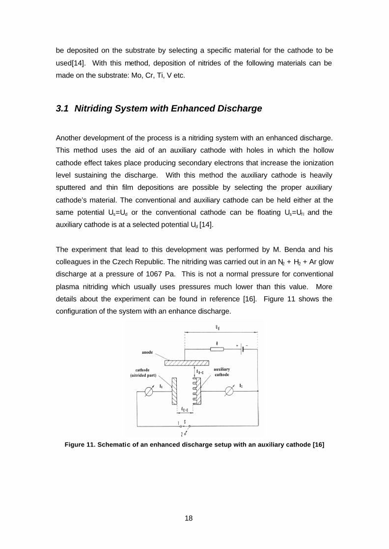
Another development of the process is a nitriding system with an enhanced discharge.
This method uses the aid of an auxiliary cathode with holes in which the hollow
cathode effect takes place producing secondary electrons that increase the ionization
level sustaining the discharge. With this method the auxiliary cathode is heavily
sputtered and thin film depositions are possible by selecting the proper auxiliary
cathode’s material. The conventional and auxiliary cathode can be held either at the
same potential Us=Ud or the conventional cathode can be floating Us=Uf l and the
auxiliary cathode is at a selected potential Ud [14].
The experiment that lead to this development was performed by M. Benda and his
colleagues in the Czech Republic. The nitriding was carried out in an N2 + H2 + Ar glow
discharge at a pressure of 1067 Pa. This is not a normal pressure for conventional
plasma nitriding which usually uses pressures much lower than this value. More
details about the experiment can be found in reference [16]. Figure 11 shows the
configuration of the system with an enhance discharge.
Figure 11. Schematic of an enhanced discharge setup with an auxiliary cathode [16]

19
3.2 Duplex Coatings
Recent research has focused on developing multi layer technologies known as duplex
coating process. In this process a thin film layer of some hard coating material like
titanium nitrides or chromium nitrides, is deposited after traditional plasma nitriding or
another plasma diffusion process like carburizing. The thin film can be deposited by
many means, one of them being the one that has just been explained with enhanced
discharge. PVD (Physical Vapor Deposition) and CVD (Chemical Vapor Deposition)
process can also be used.
This duplex coating process improves the tribological properties of the part to be
nitrided extending the life time of tooling. They are classified into two groups [14].
1. Direct DCT, i.e. deposition of coating onto nitrided or implanted substrate
surface
2. Converse DCT, i.e. nitriding or vacuum heat treatment of the coating/substrate
couple.
The direct DCT process has a problem since the nitrides formed during the nitriding
process inhibit the diffusion of elements from the coating into the steel surface. This
results in the lack of a diffusion interface between the coating and the substrate which
is very important for the adherence of the first one. On the other hand, the nitrided
layer, due to its high hardness, offers a very good mechanical support for the coating,
decreasing the risks for chipping and delamination and increasing the coating
performance.
Converse DCT, different from direct DCT, does not present this problem. The post-
coating plasma nitriding process or vacuum heat treatment stimulates the two following
processes [14]: (1) efficient inter-diffusion of the elements between the coating and the
substrate with a dramatic redistribution of the elements in the coating and (2) the
formation of intermetallic compounds when the temperature of the treatment is
sufficiently high. This two have direct effect on the adherence and on the wear
resistance of the processed part or tool.
After nitriding it is usually necessary to do a mechanical treatment of the surface in
order for it to be coated. This is because the nitriding process produces a fairly rough
20
porous surface not suitable for this kind of coatings since it does not give a good
mechanical support to it. Polishing of the nitrided surface is then needed to be able to
obtain the desire properties. The compound layer formed during nitriding, as said
before, provides a barrier for the diffusion of the coating elements in the substrate and
therefore inhibits its adherence. Another problem with the compound layer is the
possible decomposition of iron nitrides at temperatures above 520 °C generating a very
soft α-Fe layer usually called the black layer which also fails to be a good mechanical
support for the coating [18] and has to be removed before coating. In plasma nitriding,
the process can be controlled in certain way as to prevent the formation of this
compound layer. Thus it seams that this problem can be overcome. The process by
which you obtain no compound layer during plasma nitriding is usually known as bright
nitriding. This is accomplished by controlling the nitrogen potential of the atmosphere
and the nitriding time and temperature.
3.3 Low-Pressure Nitriding Using a Microwave Discharge
One of the major differences between the plasma nitriding process and the thin films
deposition process such as PVD, is the pressure at which they work. While plasma
nitriding works at a pressure between 50 to 500 Pa, the deposition processes work at
pressures between 0,1 and 10 Pa. As the formation of the compound zone, as earlier
explained, pressure difference is another important limitation for a duplex coating to be
carried out in the same process chamber. Having overcome the problem of the
compound layer formation by performing a bright nitriding process, the investigations
have focused on finding a good method for decreasing the nitriding pressures down to
the coating pressures.
Electron cyclotron resonance (ECR) microwave discharges, have been found to be
very suitable as a method for reducing the nitriding pressures by plasma-assisted
nitriding [14]. This is due to (i) high plasma reactivity induced by effective production of
active species at elevated electron temperatures and densities, (ii) a high degree of
plasma uniformity over large areas and (iii) no contamination of substrate surfaces from
additional electrodes ( e.g. heated W filaments in triode systems) [14]. Further
information about the equipment used and the experiments, can be found in reference
[14].
21
3.4 Continuous Duplex Process Using a Bipolar Pulsed Power
Supply.
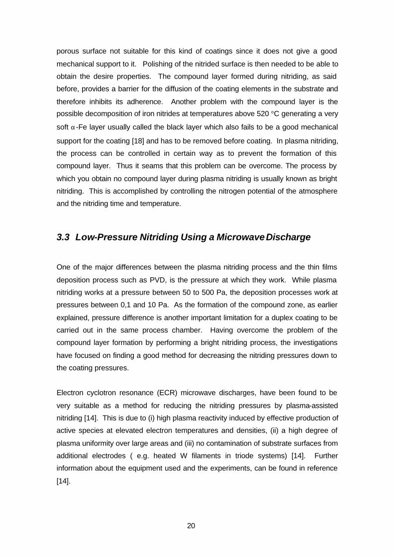
The modification of a conventional nitriding equipment for continuous duplex coating
using a bipolar pulsed DC power source has also been reported. B. Buecken and his
colleagues from the technical University Bergakademie Freiberg in Germany,
accomplished the PVD deposition of a titanium nitride film in a modified nitriding
equipment [19]. In this case, and to overcome the pressure difference at which the
different process work, an intermediate vacuum pumping was performed in order to
lower the pressure from the nitriding pressure of 300 Pa to the PVD required pressure
of 0,25 Pa. Figure 12 schematically shows the equipment used for this process.
Figure 12. Technical principle of combined plasma nitriding in
the TINA 900: 1, double-walled chamber; 2, substrate holder;
3,hollow cathode; 4, evaporator; 5, auxiliary anode; 6, radiant
heating system; 7, thermocouple [19]
More information about the process and the experiments can be found in reference
[19].
A continuous duplex process using the same chamber has also been reported by the
author in reference [18]. In this case, the equipment used was a commercial
equipment for PVD coatings in which nitriding experiments followed by a PVD CrN
coating had been performed. Several test showed that the nitriding efficiency at high
22
vacuum (0,7 Pa) was comparable to that of a normal nitriding equipment. The
adherence, mechanical and fatigue resistance of the duplex treated part were better
than the ones from a part that was only PVD CrN coated. To accomplish this and
avoid possible delamination, bright nitriding was performed. More information about the
experiment can be found in reference [18].
3.5 Active Screen Plasma Nitriding.
Active screen plasma nitriding is a fairly novel method for nitriding developed to
overcome many of the problems found on conventional dc plasma nitriding. In this
process the entire workload is surrounded by a metal screen or cage on which a high
voltage cathodic potential is applied. The work table and the parts to be treated are
connected to a floating potential or to a relatively lower bias voltage e.g. –100 to –
200V, so it is on the screen, rather than on the parts’ surface that the plasma is formed.
The plasma heats up the screen and this radiates to the workload obtaining the desired
temperature. Active species from the plasma are encouraged to pass through the
screen and will be deposited on the components surface. With this method problems
like surface damage caused by arcing, the hollow cathode effect and the edge defect
found in conventional dc plasma nitriding are avoided [20].
In AS plasma nitriding, iron nitrides from the screen are deposited on the parts surface
liberating nitrogen which will further diffuse into the substrate surface. Without the iron
nitrides being deposited on the part, the nitrided case depth will be minimal and with
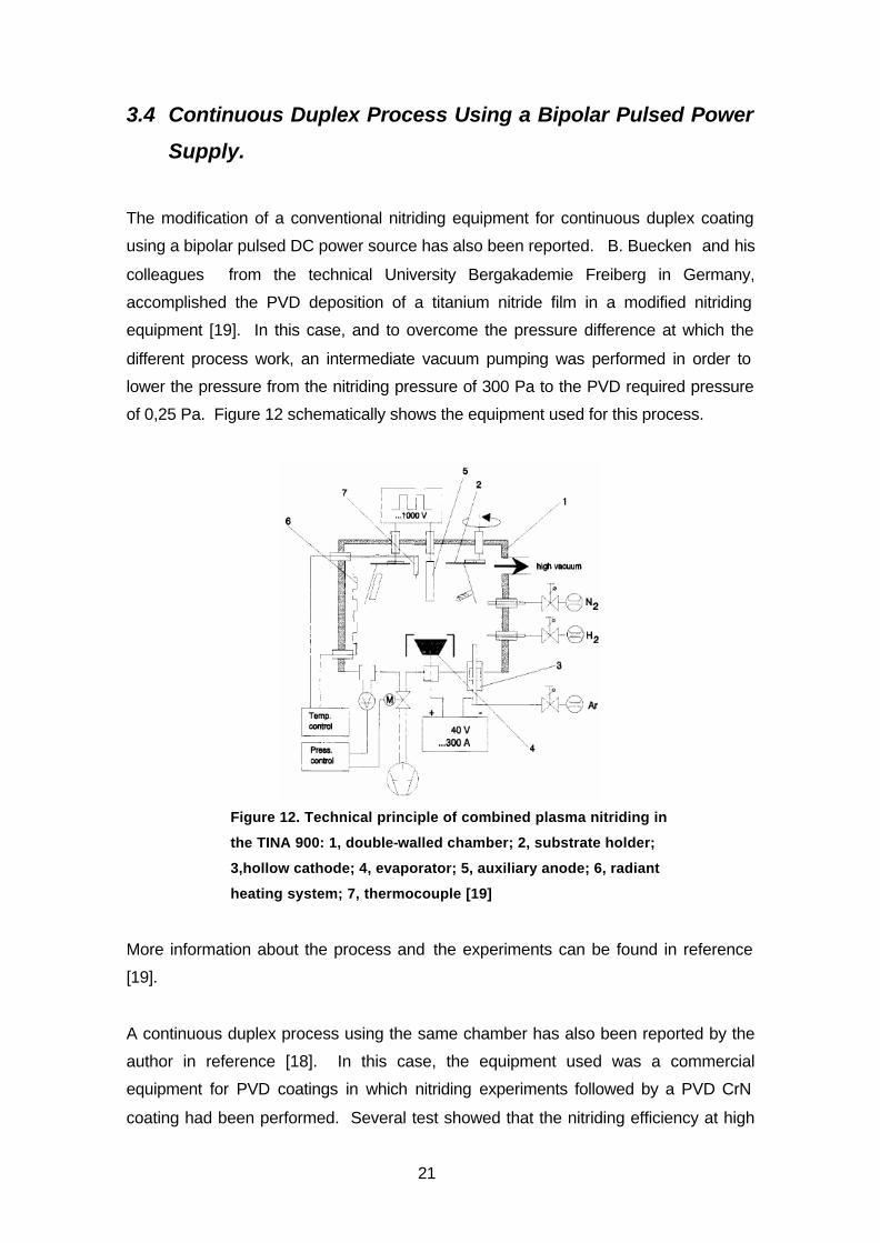
non-uniform deposition, non-uniform case depth will be obtained [20]. Figure 13
schematically shows the setup used for the active screen plasma experiment perform
by the authors of reference [20].
Figure 13. Active screen
plasma nitriding schematic
drawing : 1, sample; 2, dummy
sample for temperature control;
3,isolated sample table; 4, mesh
cylinder, cathode ; 5, top lid,
cathode; 6, furnace wall [20]
23
4 PLASMA TECHNOLOGY AND NITRIDING EQUIPMENT
A plasma is a gas containing charged and neutral species, including some or all of the
following: electrons, positive ions, negative ions, atoms, and molecules. An important
parameter of a plasma is the degree of ionization which is the fraction of the original
neutral species (atoms and/or molecules) which have become ionized. Plasmas with a
degree of ionization much less than unity are referred to as weakly ionized. The
presence of a relatively large population of neutral species will dominate the behavior
of this type of plasma. In fully ionized plasmas, the degree of ionization approaches
unity, and neutral particles play little or no role [15].
To form and sustain a plasma requires some energy source to produce the required
ionization. In steady state, the rate of ionization must balance the losses of ions and
electrons from the plasma volume by recombination and diffusion or convection to the
boundary. Plasma is often referred to as the fourth state of matter since it occurs by
adding energy (heat) to a gas. There is not, however, a distinct phase change in going
from a neutral gas to a plasma; the process is more continuous [15].
The plasmas normally used for materials processing are initiated and sustained by
electric fields which are produced by either direct current (dc) or alternating current (ac)
power supplies. Typical ac frequencies of excitation are 100 kHz, at the low end of the
spectrum, 13.56 MHz in the radio frequency (rf) portion of the spectrum, and 2.45 GHz
in the microwave region. These plasmas are also referred to as electric discharges,
gaseous discharges, or glow discharges (the latter because they emit light). As has
been shown before, different technologies can be used today for plasma nitriding that
use different types of plasma discharges, but we will focus on glow discharge plasmas
which are more widely used in industry for this process [15].
Plasmas are a very efficient way to couple non-thermal energy from an electric field to
materials processing. Plasmas are used for a wide variety of processes, among which
are the thermo chemical diffusion processes, thin film deposition, etching, cleaning,
cutting, welding etc.
Even though plasma techniques are normally used under different values of vacuum,
there are some researchers working on plasmas at one atmosphere pressure applied
to materials processing techniques. This investigation might eventually lead to lower

24
the costs for plasma processing equipment and more industrial applications can be
built.
4.1 The Importance of Collisions in Plasmas
As earlier stated, the plasma state is an ionized gas. This ionization occurs due to
collisions between different particles present in this gas. Accelerated electrons due to
the electric field present in plasma generators, leaving the cathode, will collide with
atoms or molecules from the gas and can create ionized particles. Some of the
collisions of the emitted electrons with the atom or molecule from the process gas do
not have the sufficient energy as to kick out an electron from the atom they have just
collided with, thus exiting its electrons to a higher energy level. This exited particles
have a defined life time and will eventually come back to their original energy state
emitting photons in the process. This emission of light is what gives the name of glow
discharge to some types of plasmas .
Figure 14a. Electron generation in an electric field and ionization by electro-atom collision [15]
Figure 14b. Ion bombardment, secondary electron generation and ionization of gas atoms [15]
Figure 14a shows the process of electron generation and how it gives rise to the
plasma between anode and cathode. Figure 14b shows how ions exit the bulk plasma
region and are accelerated out of the plasma and through the sheath into de cathode.
The secondary electron emission is the name used for the process of an electron
colliding with an atom and liberating a second electron from it. This process not only
frees another electron that will be accelerated in the magnetic field, but will also ionize
25
the gas atom which will be accelerated towards the cathode. Secondary electrons can
arise from the cathode as well as from the gas.
Collisions fall into two categories, elastic collisions which are those for which the
internal energy of the elements do not change, and inelastic collisions, for which the
internal energy (excitation level) of the colliding elements will change [15].
Thus, it is the collisions between the gas species found in the process chamber that
sustain the plasma. It is important then to create a proper environment in the process
chamber to be able to allow this collisions and to obtain the desired result from them. It
is here vacuum plays an important role in sustaining the plasma. As was said before,
electrons are accelerated due to the electric field present in the reactor. The kinetic
energy electrons gain is directly related to the force exerted by the electric field on the
electron and the distance this electron travels before colliding and transferring its
energy to the collided particle. The force of the electric field is directly related to the
voltage, and the distance the electron travels before a collision is directly related to the
mean free path in the surrounding gas. The mean free path on its own is directly
related to the gas pressure in the chamber.
Too low pressure could cause the electron to travel freely without any collision and hit
the anode. Too high pressure, on the other hand, could make the electron collide with
a particle right after leaving the cathode and before gaining enough kinetic energy to
ionize the process gas and create secondary electron emissions.
Collisions can be divided into different important groups which are:
Electron-Neutral, elastic collision: The probability for this collisions to occur,
depends on the electron speed and the mass of the neutral atom in the collision. Since
the mass of the neutral atom is greater than that of the electron, low energy is
transferred from the electron to the neutral. The first one on the other hand, is highly
influenced and its trajectory will be drastically changed.
Electron-Electron collisions: Due to electrons having the same mass the collision
process is a very efficient way of energy exchange. For highly ionized plasmas (degree
of ionization between 10-4 to 10-3), the electron-electron collision will play a very
important role, while for lower degrees of ionization, electron-neutral collision will be
more important.
26
Electron-impact inelastic collisions: In this collision, almost all the energy from the
speeding electron is transferred to the collided particle and several reactions can occur.
Relaxation is one of these reactions. In this case, the electron of a molecule is exited
to a higher energy level due to the charge of the passing electron. Relaxation form this
state is almost instantaneous (10-8 s) [9] in most cases and is accompanied by the
emission of a photon whose wavelength corresponds to the exited electron’s energy
level drop. This emission lines give plasmas their glow and also provide for qualitative
analysis of the plasma’s atomic composition by Optical Emission Spectroscopy (OES)
[9].
The relaxation process by photon emission is sometimes quantum-mechanically
impeded and then the atom can reach a metastable state for many seconds until it
finally radiates a photon or is deactivated in a collision. The lightest gases have the
most energetic metastable states. Argon, which is sometimes used during the plasma
nitriding process, has a metastable energy of 11,7 eV[9]. This metastables can
contribute to dissociation of weaker species by “Penning” reactions:
AB + Ar* A + B + Ar
Dissociation reactions occur at higher electron impact energy than excitation reactions.
AB + e A+ + B + 2e (dissociative ionization)
AB + e A + B + e (dissociation)
AB + e A + B- (dissociative electron attachment)
Free radicals produced are very active chemically because of their unsatisfied bond.
The third reaction that occurs in the plasma is Ionization, which is the one that requires
higher electron’s impact energy. Ionization can be simple
A + e A+ + 2e
Or dissociative as shown before.
Ionization supports the plasma by supplying electrons in replacement of those that are
lost to the walls of the nitriding chamber.
Ion collision processes: There are a few ion collision processes important for the
discharge. One of them is the secondary electron emission from the cathode due to ion
27
impact. This is important because the electrons emission help to sustain the plasma.
The second one is ion-ion collision where energy is transferred from an energized ion
to a non energized one. This results in the loss of an energetic ion and this
phenomena happens more frequently in the sheath region of the discharge
schematically shown in picture 14b.
4.2 Type of Plasma Used in Plasma Nitriding: Glow Discharge
The plasma typically used for nitriding, or in general, for thermo chemical diffusion
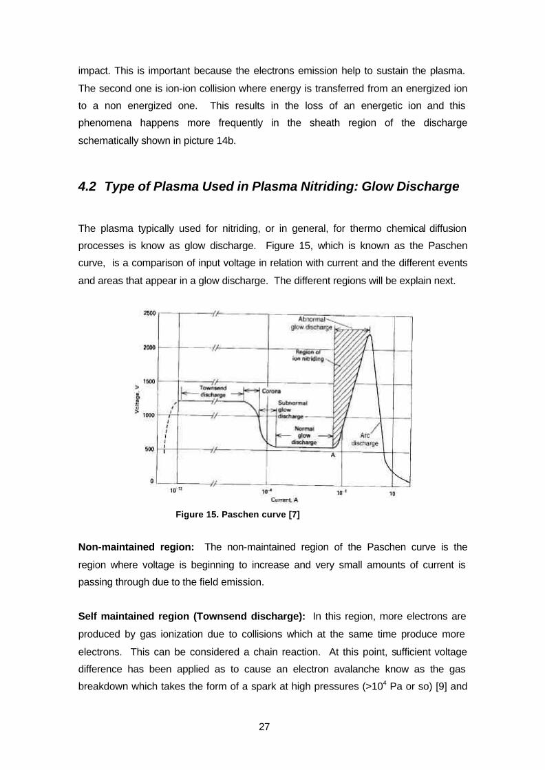
processes is know as glow discharge. Figure 15, which is known as the Paschen
curve, is a comparison of input voltage in relation with current and the different events
and areas that appear in a glow discharge. The different regions will be explain next.
Figure 15. Paschen curve [7]
Non-maintained region: The non-maintained region of the Paschen curve is the
region where voltage is beginning to increase and very small amounts of current is
passing through due to the field emission.
Self maintained region (Townsend discharge): In this region, more electrons are
produced by gas ionization due to collisions which at the same time produce more
electrons. This can be considered a chain reaction. At this point, sufficient voltage
difference has been applied as to cause an electron avalanche know as the gas
breakdown which takes the form of a spark at high pressures (>104 Pa or so) [9] and
28
the form of a much more diffuse “glow” at lower pressures. After breakdown, the
plasma is “ignited” and a continuous flow of electrons and ions between the cathodes is
sustained by impact ionizing collisions in the gas phase. The electrons that initiate this
avalanche, are secondary emitted electrons from the cathode due to ion bombardment.
Transition region (corona): In this region, there is a voltage drop since there is a big
reduction of the current resistance. The voltage stability, then, can not be maintained.
Subnormal glow discharge: In this region, a very fussy glow can already be seen
since the glow has been ignited.
Normal glow region: As glow discharge current is allowed to increase, the glow
column between the electrodes will widen as to keep a constant current density at the
cathode. It can be seen that the glow completely covers the work pieces.
Abnormal glow region: Once the glow has covered the whole area of the cathode,
the plasma enters in the abnormal glow discharge region. In this region, the current
density and the voltage are allowed to increase. This is the region where plasma is
used for plasma nitriding.
Arc discharge region: In the arc discharge region, a dramatic voltage drop can be
observed. At this point, the current density will increase to very high values and
overheating of the part can appear. This arc discharges can be seen through the
chamber’s glass as a lightning and are to be avoided.
As explained before, today’s plasma equipment are powered and controlled by pulsed
dc power sources. This power sources prevent the arcing that could easily occur with
prior continuous dc power sources.
4.3 Plasma Nitriding Equipment Used Today
Even though there are many different new technologies and developments in the
plasma nitriding field, and in the nitriding field combined with other surface processes,
there are two main categories in which today’s plasma nitriding furnaces can be
classified. These two categories will be explained next.
29
4.3.1 Cold-Wall Continuous dc Plasma Furnaces
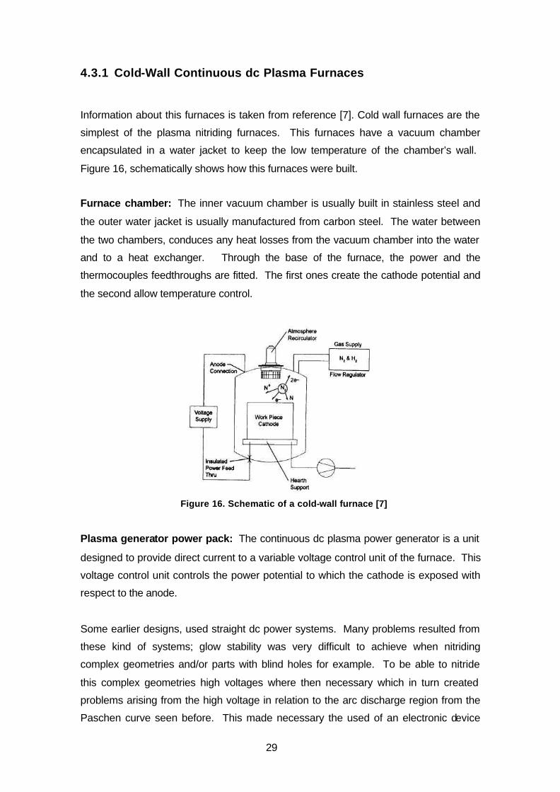
Information about this furnaces is taken from reference [7]. Cold wall furnaces are the
simplest of the plasma nitriding furnaces. This furnaces have a vacuum chamber
encapsulated in a water jacket to keep the low temperature of the chamber’s wall.
Figure 16, schematically shows how this furnaces were built.
Furnace chamber: The inner vacuum chamber is usually built in stainless steel and
the outer water jacket is usually manufactured from carbon steel. The water between
the two chambers, conduces any heat losses from the vacuum chamber into the water
and to a heat exchanger. Through the base of the furnace, the power and the
thermocouples feedthroughs are fitted. The first ones create the cathode potential and
the second allow temperature control.
Figure 16. Schematic of a cold-wall furnace [7]
Plasma generator power pack: The continuous dc plasma power generator is a unit
designed to provide direct current to a variable voltage control unit of the furnace. This
voltage control unit controls the power potential to which the cathode is exposed with
respect to the anode.
Some earlier designs, used straight dc power systems. Many problems resulted from
these kind of systems; glow stability was very difficult to achieve when nitriding
complex geometries and/or parts with blind holes for example. To be able to nitride
this complex geometries high voltages where then necessary which in turn created
problems arising from the high voltage in relation to the arc discharge region from the
Paschen curve seen before. This made necessary the used of an electronic device
30
that worked as a arc detector and as soon as the arc was detected, it was suppressed
by the control unit.
This arcing problem led to mechanical as well as metallurgical defects on the part due
to overheating. On the other hand, lower pressures had to be used to avoid this arcing
and the glow was not able to cover the complex geometries of some parts.
Heating elements: A cold wall furnace did not normally have heating elements. Heat
to the part was generated by the kinetic energy transferred to it by ion bombardment
from the plasma. In some cases, furnace manufacturers will design supplementary
heating elements found within the furnace chamber to assist the plasma heating. It
was necessary to keep in mind that this elements would also be nitrided.
Furnace thermocouples: In plasma nitriding, the temperature to be measured is the
part’s temperature and not the process chamber temperature as in conventional heat
treatment. Thus the thermocouple has to be in contact with the part. The part and
process temperature are measured by considering the thickest and the thinnest part of
the load. If the thermocouple can not be attached to the part, a dummy test part, which
is representative of the load, has to be placed in the chamber and the thermocouple
has to be attached to it. Temperature of the part should be held at a tolerance of ±5
°C. The thermocouple has to be isolated from the anode of the furnace, i.e. the
process chamber.
Gas flow: To assure repeatability of the process, it is mandatory to assure a good gas
flow control. Earlier equipment used flow meters, but the accuracy was not very good.
A later development was the use of micrometer needle valves, but these too could not
offer a great level of accuracy. A more accurate development for achieving a good
control of gas flow, is the mass-flow controller.
Gas flow setup depends on the work surface area. Different work surface area require
different gas flow. This one also depends and varies according to surface metallurgy
requirements. The reason for the low gas consumption in plasma nitriding is that no
“sweep” gases are used and only the gas necessary for the process is used.
Vacuum pump: Chamber pressure is normally controlled by a simple mechanical
vacuum pump, a rotary-vane vacuum pump or a combination of a vacuum pump and a
roots blower. With an operating pressure between 10 to 500 Pa, the roots blower
improves the system pumping speed and compression. Lower vacuum diffusion
31
pumping systems are used only when a very clean inner chamber is required and low
residual gas values are necessary.
The vacuum pump-out port is usually locate in the hearth. The furnace hearth and the
vacuum pump are usually connected by a flexible stainless steel connector.
Cathode and Anode: The vacuum vessel acts as the anode potential, and the furnace
hearth is connected as the cathode. The principal concern with the power feedthrough
is that it be insulated with a very dense ceramic material with high insulation
characteristics.
4.3.2 Hot-wall Pulsed dc Plasma Nitriding
Hot wall pulsed plasma technology is in many aspects the same as cold wall
continuous dc technology. Their main difference is in that the hot wall furnace does not
longer uses plasma to heat up the parts, instead, the vacuum chamber has heating
elements in the outside that are also covered by an insulating bell. Figure 17 shows
the schematics of the hot-wall technology. Hot-wall plasma furnaces do not use the
plasma to heat up the load as do cold-wall plasma furnaces. Instead, the load is
heated by mean of the external heating elements to a temperature of around 200 °C
before the plasma is ignited. This allows for the plasma to operate at lower voltages
(400 to 500V) than for cold-wall furnaces (600 to 800V), away from the arc discharge
region. Plasma then, is only used for surface preparation, gas ionization and to
maintain the load temperature. The current density needed for the last one,
corresponding to about 1-2 A/m2, can be reached at lower voltages due to the already
heated workload. This is not possible with cold-wall furnaces where the current density
needed is approximately 10 A/m2.
An advantage of hot-wall furnaces is that the heating time for the load is shortened in
comparison with cold-wall furnaces, thus reducing the batch time for each process.
Pulsed power supply allows for the use of high voltages without the risk of arcing, thus
the voltage can be kept constant as the part heats up since the temperature is
controlled by the length of the pulses and therefore all the other parameters as
pressure for example, do not have to be changed. On the other hand, cold-wall
furnaces need to change the voltage as the temperature of the load increases and
therefore other parameters have to be changed in order to control the plasma.

32
Figure 17. Hot-wall furnace [7]
The use of pulsed power also allows for the wall temperature to go as high as 650 °C
without the risk of over heat build up in the wall which would in turn radiate heat to the
load obligating to lower the voltage input to levels where the plasma could not be
sustained. Keeping the wall surface at this maximum temperature is important, so the
hot-wall furnaces have fans that extract heat from the walls. Cold-wall furnaces, on the
other hand, need to keep the walls at room temperature and need water cooled jackets
which are expensive to build. Today, most of the equipment being produced is being
built under the pulsed dc technology philosophy due to its great advantage over
continuous dc type furnaces.
33
5 NITRIDING EXPERIMENTS ON HOT-WORK TOOL STEEL
As a practical experiment, three samples of hot work tool steel grade Orvar Supreme
(H13 type), were heat treated with different nitriding methods. Sample number one
was Gas nitrided, sample number two was nitrocarburized, and sample number three
was plasma nitrided. The process parameters for each sample are described below.
Sample 1 2 3
Process Gas Nitriding Nitrocarburizing Plasma Nitriding
Process Temperature 510 °C 580 °C 480 °C
Process gas. Cracked Ammonia
NH3
N2: 55%
NH3: 40%
O2: 5%
N2: 25%
H2: 75%
Process Time 30 h 4 h 30 h
Compound layer
Thickness
10 µm 11,3 µm 1,6 µm
Total layer thickness. 159 µm 147 µm 138,6 µm
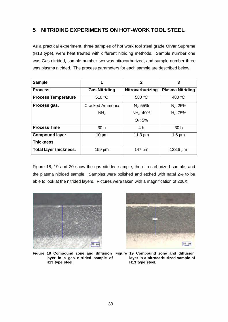
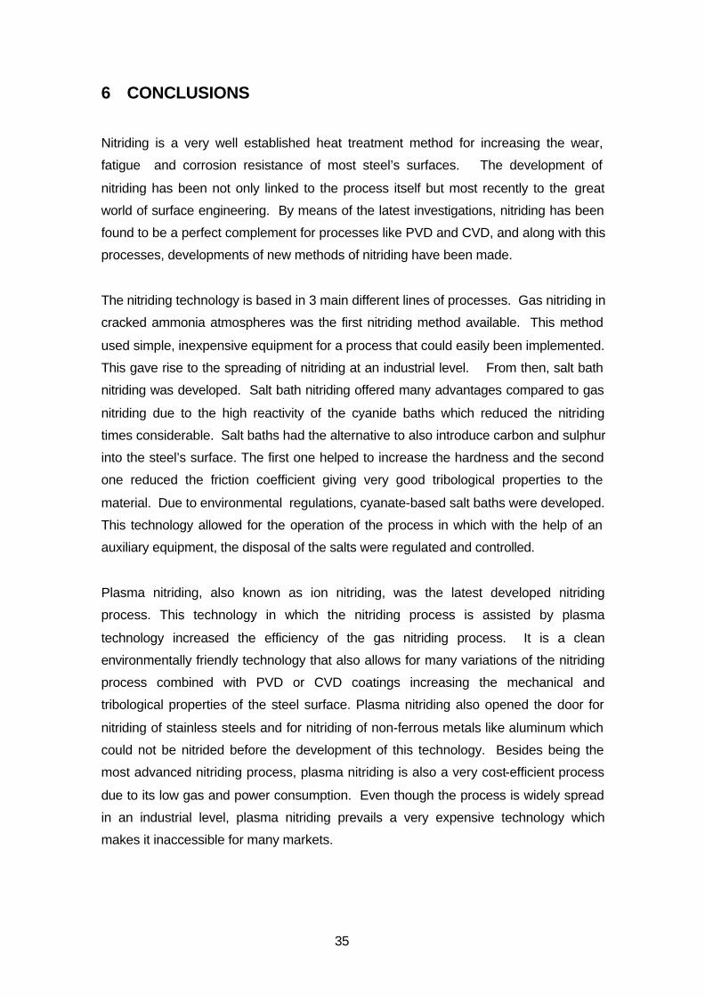
Figure 18, 19 and 20 show the gas nitrided sample, the nitrocarburized sample, and
the plasma nitrided sample. Samples were polished and etched with natal 2% to be
able to look at the nitrided layers. Pictures were taken with a magnification of 200X.
Figure 18 Compound zone and diffusion
layer in a gas nitrided sample of H13 type steel
Figure 19 Compound zone and diffusion layer in a nitrocarburized sample of H13 type steel.

34
Figure 20. Compound zone and diffusion layer
in a plasma nitrided sample of H13 type steel.
5.1 Experiments Discussion
The gas nitrided sample, as well as the nitrocarburized sample, show a thick
compound layer compared to the plasma nitrided sample. The reason for this is the
nitrogen potential in the furnace atmosphere. It seems that the nitrogen potential in the
two first cases was somewhat higher than that of the plasma nitriding furnace. This
creates a higher nitrogen concentration gradient from the atmosphere to the substrate
surface and core that gives rise to a fast formation of γ’ and ε nitrides at the first stages
of the process.
It is important to see that by the gas nitriding process, a deeper penetration of nitrogen
was found into the substrate. This contradicts the statement made before about the
plasma process being more efficient. The reason for this result is the temperature
difference between the two process. While gas nitriding was run at a temperature of
510 °C, plasma nitriding was run at a temperature of 480 °C. At higher temperatures,
the diffusion of nitrogen into steel increases.
To prove this, is enough to look at the nitriding depth of the nitrocarburized sample.
This sample obtained a case depth just bellow the other two samples and with a
process time of only 4 hours. This, again, can be explained due to the temperature of
this process which was 580 °C.
35
6 CONCLUSIONS
Nitriding is a very well established heat treatment method for increasing the wear,
fatigue and corrosion resistance of most steel’s surfaces. The development of
nitriding has been not only linked to the process itself but most recently to the great
world of surface engineering. By means of the latest investigations, nitriding has been
found to be a perfect complement for processes like PVD and CVD, and along with this
processes, developments of new methods of nitriding have been made.
The nitriding technology is based in 3 main different lines of processes. Gas nitriding in
cracked ammonia atmospheres was the first nitriding method available. This method
used simple, inexpensive equipment for a process that could easily been implemented.
This gave rise to the spreading of nitriding at an industrial level. From then, salt bath
nitriding was developed. Salt bath nitriding offered many advantages compared to gas
nitriding due to the high reactivity of the cyanide baths which reduced the nitriding
times considerable. Salt baths had the alternative to also introduce carbon and sulphur
into the steel’s surface. The first one helped to increase the hardness and the second
one reduced the friction coefficient giving very good tribological properties to the
material. Due to environmental regulations, cyanate-based salt baths were developed.
This technology allowed for the operation of the process in which with the help of an
auxiliary equipment, the disposal of the salts were regulated and controlled.
Plasma nitriding, also known as ion nitriding, was the latest developed nitriding
process. This technology in which the nitriding process is assisted by plasma
technology increased the efficiency of the gas nitriding process. It is a clean
environmentally friendly technology that also allows for many variations of the nitriding
process combined with PVD or CVD coatings increasing the mechanical and
tribological properties of the steel surface. Plasma nitriding also opened the door for
nitriding of stainless steels and for nitriding of non-ferrous metals like aluminum which
could not be nitrided before the development of this technology. Besides being the
most advanced nitriding process, plasma nitriding is also a very cost-efficient process
due to its low gas and power consumption. Even though the process is widely spread
in an industrial level, plasma nitriding prevails a very expensive technology which
makes it inaccessible for many markets.

36
Surface engineering is a very important field of work since it helps to increase the
duration of tools and machinery parts, but also to reduce their cost by making it
possible to use lower quality bulk or core materials and still obtain better performance.
Nitriding is part of the surface engineering field and plasma nitriding opens the door for
the combinations of it with many other different techniques and it makes it a very
important process which will be further developed in the future.

37
7 REFERENCES
1. THELNING, Karl-Erik, Nitriding, Steel and its heat treatment: Bofors Handbook. BUTTERWORTHS, London 1975. p 377-427
2. http://www.key-to-steel.com/Articles/Art117.htm
3. M. Berg a,*, C.V. Budtz-Jørgensen a, H. Reitz b, K.O. Schweitz a, J. Chevallier
a, and P. Kringhøj a, J. Bøttiger a: On plasma nitriding of steels. on Surface and Coatings Technology 124 (2000) 25–31
4. S. A. Gerasimov,1 A. V. Zhikharev,1 E. V. Berezina,1 G. I. Zubarev,1 and V. A.
Pryanichnikov1: New Ideas on the Mechanism of Structure Formation in Nitrided Steels. On: Metal Science and Heat Treatment, Vol. 46, Nos. 1 – 2, 2004
5. Smith, Eduard H. Mechanical Engineer’s Reference Book (12th edition).
Butterworth Heinemann, Oxford, 1998
6. FUNATANI, K.: Low-Temperature Salt Bath Nitriding of Steels. On: Metal Science and Heat Treatment, Vol. 46, Nos. 7 – 8, 2004
7. PYE, David, Practical Nitriding and Ferritic Nitrocarburizing. ASM International.
Ohio 2003
8. T. Czerwiec*, N. Renevier1, H. Michel, Low-temperature plasma-assisted nitriding. Surf. Coating Technology 131 (2000) 267-277
9. SMITH, L. Donald, Thin-Film deposition – Principles and Practice. McGraw-Hill,
Inc.1995
10. K.-T. Rie: Recent advances on plasma diffusion processes . On: Surface and Coating Technology 112 (1999) 56-62
11. H. Koch, L.J. Friedrich, V. Hinkel, F.Ludwig, B. Politt, and T. Schurig, Hollow
cathode discharge sputtering device for uniform large area thin film deposition. J. Vac. Sci. Technol. A 9, 2374 (1991)
12. P. Egert a,b, A.M. Maliska a, H.R.T. Silva a, C.V. Speller a. Decarburation
during plasma nitriding. On: Surface and coating Technology 221 (1999) 33-38.
13. C. Alves Jr. a,*, J.A. Rodrigues b, A.E. Martinelli. The effect of pulse width on the microstructure of d.c.-plasma-nitrided layers. Surface and Coatings Technology 122 (1999) 112-117.
14. J. Musil, J. Vlcek, M. Ruzicka: Recent progress in plasma nitriding. On:
Vacuum 59 (2000) 940-951.
15. Rossnagel, M. Stephen, Cuomo, J. Jerome and Westwood, D. William. Handbook of Plasma Processing Technology – Fundamentals, etching, deposition and surface interactions. Noyes Publications. New Jersey, 1990
38
16. M. Benda, J. Vlcek, and V. Cibulka. Plasma nitriding combined with a hollow cathode discharge sputtering at high pressures. J. Vacuum Science and Technology. A 15 (1997) 2636-2646
17. KUBASCHEWSKI, Ortrud. IRON-Binary Phase Diagrams. Springer-Verlag.
Berlin 1982
18. J.-D. Kamminga *, R. Hoy , G.C.A.M. Janssen , E. Lugscheider , a, a b c M. Maesc. First results on duplex coating without intermediate mechanical treatment. On: Surface and Coatings Technology 174 –175 (2003) 671–676
19. B. Buecken, G. Leonhardta R. Wilberga, K. Hoecka, H.-J. Spies. Direct
combination of plasma nitriding and PVD hardcoating by a continuous process. On: Surface and Coatings Technology, 68/69 (1994) 244—248
20. C. X. Li, T. Bell, and H. Dong. A study of active screen plasma nitriding. On:
Surface Engineering 2002 Vol. 18 No. 3. 174-181