Embed Size (px)
Citation preview

1
Thank you for buying a GESAN generator set.
This manual has been written to assist you in maintaining and operating yourgenerator set correctly. Please read it carefully before putting the machine intooperation so as to become familiar with the precautions to be taken during useand be able to perform maintenance in ideal conditions.
Please keep this manual on hand for consultation at all times and ensure it isincluded with the machine should it be re-sold.
GRUPOS ELECTROGENOS GESAN, S.A. is constantly striving to improve itsproducts, and regularly introduces changes to the equipment it supplies. Forthis reason the characteristics and information contained in this manual may bemodified without prior notice and without incurring any obligation.
If any problems or queries arise, please contact your distributor.

2
CONTENTS
SAFETY INSTRUCTIONS..................................................................................3
GENERAL DESCRIPTION .................................................................................6
LABELS ..............................................................................................................7
BEFORE USE.....................................................................................................91.1 Oil recommended ...........................................................................9
1.2 Oil level check ................................................................................ 91.3 Fuel recommended .......................................................................101.4 Fuel level check ..........................................................................10
OPERATION.....................................................................................................121. Starting the engine.........................................................................12
1.1 Starting using the electric starter......................................121.2 Starting using the starter rope..........................................14
2. Running the engine.........................................................................163. Stopping the engine........................................................................164. Operating the generator set............................................................175. Commissioning...............................................................................18
MAINTENANCE ................................................................................................181. Maintenance schedule...................................................................192. Oil change......................................................................................19
2.1 Oil filter change................................................................203. Air filter ..........................................................................................20
3.1 Air filter change................................................................21 4. Spark-plug maintenance...... ......................................................... 21
HANDLING, TRANSPORT AND STORAGE .................................................. 221. Handling ........................................................................................222. Transport ...................................................................................... 233. Long term storage.............................. .......................................... 23
WIRING DIAGRAMS ........................................................................................ 24
TROUBLESHOOTING .................................................................................... 27
CHARACTERISTICS ....................................................................................... 28

3
SAFETY INSTRUCTIONS
Please read carefully the following instructions for your own safety and thesafety of others :
1. Make sure that the control panel is well-lit if you run your generator set inpoor operating conditions.
2. Make sure that you know how to stop the generator set in case ofemergency and familiarise yourself with its controls and power outlets.
Do not permit operation by someone unfamiliar with the generator set.
Do not let children operate the generator set without the help of an adult.
Children and pets must be kept at a safe distance from the engine, in order toavoid burns or injury.
3. Carry out all necessary checks before starting the generator set in orderto avoid accidents or damage to the equipment.
4. Earth the generator set as well as the load properly.
5. Do not operate the generator set when it is raining or where there issnow. YOU MAY BE ELECTROCUTED .
Do not get the generator set wet, or operate it with wet hands ..
6. Do not connect the generator set to the mains. Connection should becarried out by a qualified electrician in accordance with all applicable standardsand regulations.
A poorly made connection may cause current returns which could lead to theelectrocution of anybody working on the mains.
7.- The engine exhaust emits sufficient heat to set some substances on fire.
Keep the generator set away from buildings and other equipment (at leastone metre).

4
Keep all inflammable substances away from the generator set.
Wait until the engine has cooled down before carrying out maintenance orstoring it.
8. The fuel used is highly inflammable and volatile :
Ensure that the engine is not running before filling the fuel tank and that thepremises are sufficiently ventilated.
Do not over-fill the fuel tank. After filling, ensure the fuel cap is properlyclosed.
Do not get near flames or sparks while filling the fuel tank.
DO NOT SMOKE near the generator set.
Keep the generator set on a firm, level surface , otherwise fuel may spill andcatch light.
9. Exhaust fumes from the engine are poisonous:
Do not operate the generator set in a closed environment.
If operating the set in an enclosed space, provide adequate ventilation anddirect the exhaust fumes out of the area.
10. If the generator set is used in a place where damp and dust areunavoidable, it must be dried and cleaned regularly .
11. At the slightest abnormality, stop and disconnect the set . Locate andcorrect the fault before starting up again.
12. Regularly inspect all electrical cables. If damaged cables or hazardoussituations are found, stop the unit immediately and replace or correct the faultycables before starting up again.
13. Handle batteries with care. Batteries give off explosive gases;keep sparks, flames and cigarettes well away. Provide adequate ventilationwhen charging or using batteries in enclosed spaces.
Batteries contain sulphuric acid (electrolyte). Contact with the skin oreyes can cause severe burning. Wear protective clothing and a protectivemask.
If electrolyte comes into contact with skin, wash with water.
If electrolyte comes into contact with eyes, wash eyes with water for at least 15minutes and seek medical assistance immediately.

5
Electrolyte is poisonous. If you swallow it, drink large amounts of water or milk,and follow with milk of magnesia or vegetable oil and seek medical assistance.
Use only distilled water in batteries. Tap water will shorten battery life. If thebattery is filled above the maximum level the electrolyte will overflow causingcorrosion of the engine or adjacent parts. Clean away electrolyte which hasbeen spilled.
14. Used oil can cause skin cancer in cases of prolonged andfrequent contact. Although this is unlikely, hand washing after contact withused motor oil is recommended.
KEEP OUT OF THE REACH OF CHIDREN.
For further information or enquiries please contact :
GRUPOS ELECTROGENOS GESAN S.A.Polígono Malpica-Alfindén, c/ Encina, nº 850171 La Puebla de Alfindén (Zaragoza)SPAINPhone: (+34) 976 107 332 Fax: (+34) 976 107 366E-mail: [email protected]

6
GENERAL DESCRIPTION
G 12000 H, G 12 TF H
1- Frame 13- Control panel2- Engine 14- Ignition key box3- Alternator 15- On light4- Engine dampener 16- 230 V socket5- Alternator dampener 17- Circuit breaker6- Fuel filler cap 18- Voltmeter7- Fuel tank 19- Hours run meter8- Battery 20- 230 V socket (G 12000 H)9- Fuel tap 400 V socket (G 12 Tf H)
10- Air filter 11- Exhaust pipe 12- Engine oil drainage plug

7
LABELS
On your generator set you will find the following labels:
LABEL No. 1(UNDEFINED DANGER)
LABEL No. 2
LABEL No. 3
This label may indicate 230 or 400 V.
LABEL No. 4 (EARTH)
LABEL No.5 (ELECTRICAL HAZARD)

8
LABEL No. 6
For your own safety and the safety of others, please replace these labelsimmediately if lost or damaged.
LOCATION OF LABELS
Label no. 1 is located on the fuel tank, or on the air filter (as near as possible tothe exhaust outlet).This label is also found on the sides of the alternator. (See picture).
Labels 2 and 3 are located on top of the alternator. (Three phase generatorsets do not have label no. 2).
Label no. 4 is located on the frame, next to the earth screw.
Label no. 5 is located on the alternator cap and on the control panel (ifsupplied).
Label no. 6 is located on top of the fuel tank.

9
BEFORE USE
To carry out the following checks place the generator set on a firm, levelsurface.
1.1 OIL RECOMMENDED
The use of SAE 10W30 motor oil is recommended, for all temperatures ingeneral.
It is however wise to select from thetable the viscosity applicable to theaverage temperature of the areawhere the set is to be used.
* The oil used is of vital importance as it affects the performance and lifeexpectancy of the engine.
*Running the engine with insufficient oil may result in major damage.
*Do not use non-detergent or vegetable oils .
1.2 OIL LEVEL CHECK
a) Remove the oil filler cap (1) and clean thedipstick (2) with a clean cloth.
b) Insert the dipstick into the oil filler vent withoutscrewing in.
c) If the level is under the minimum, addrecommended oil up to the upper limit.WARNING !!!

10
1.3 FUEL RECOMMENDED
Use car petrol, preferably UNLEADED or with a low lead content in order toreduce deposits in the combustion chamber.
Fuel tank capacity: 13 litres
* Do not use oil/petrol mixture or dirty/old fuel.
* Do not let dirt or water get into the tank.
* Do not use petrol containing alcohol.
NOTE: The warranty does not cover damage caused by the use of unsuitablefuel.
1.4 FUEL LEVEL CHECK
a) Remove fuel tank cap.
b) Add fuel and replace cap.
Fill fuel tank in well ventilated premises and with the engine turned off.
Do not smoke or allow sparks or flames in the area where the engine isrefuelled or where fuel is stored.
Do not overfill the fuel tank and make sure that filling the tank, the fuel cap hasbeen screwed on properly .
Take care not to spill fuel when filling. Fuel fumes or spilled fuel may catchlight. If fuel is spilled, ensure that the area is dry before starting the engine.
Avoid repeated or prolonged contact with the skin and avoid inhaling fumes.
KEEP FUEL OUT OF THE REACH OF CHILDREN.
WARNING !!!
WARNING !!!

11
Fuel consumption may increase with altitude as the air/ fuel mixture becomesricher. If you use your generator set at altitudes higher than 1800 m above sealevel, please consult.
At high altitude, the air/fuel mix in the carburettor becomes too rich. Engineefficiency will be reduced and fuel consumption will increase.
If the engine is always used at high altitude (above 1830m), efficiency may beimproved by installing in the carburettor a smaller diameter main fueldistributor, and by readjusting the guide screw. Have your local dealer performthese modifications on the carburettor.
A petrol engines loses 3.5% power for every 300 metres above sea level.Altitude will affect engine power even more if the carburettor is not modified.
WARNING ! ! !

12
OPERATION
1. STARTING THE ENGINE
Check that nothing is connected to the generator set output sockets.
The engine must be connected to the battery to activate the fuel cut-outsolenoid, allowing the engine to run. If the battery is disconnected, fuel flow tothe carburettor main distributor will be interrupted.
If the fuel tank has a valve, check that it is in the OPEN or ON position beforeattempting to start the engine.
1.1 STARTING THE ENGINE USING THE ELECTRIC STARTER
a) Pull the choke knob out to the CLOSE position to start a cold engine. Thechoke may not be necessary if the engine is hot or air temperature is high.
WARNING !!!
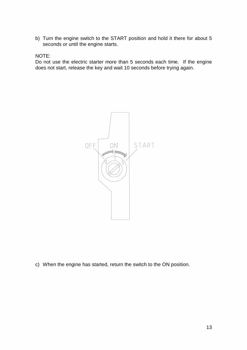
13
b) Turn the engine switch to the START position and hold it there for about 5seconds or until the engine starts.
NOTE:Do not use the electric starter more than 5 seconds each time. If the enginedoes not start, release the key and wait 10 seconds before trying again.
c) When the engine has started, return the switch to the ON position.

14
1.2 STARTING THE ENGINE USING THE ROPE STARTER
a) Pull the choke knob out to the CLOSE position to start a cold engine. Thechoke may not be necessary if the engine is hot or air temperature is high.
b) Turn the engine switch to the ON position .
c) Pull out the starter grip until it “bites” back. Then pull out sharply.

15
* Do not let the starter grip snap back against theengine. Let it pull back slowly to avoid damagingthe starter.
Oil alert system (if supplied)
The oil alert system is designed to prevent engine damage caused by a lack ofoil in the oil sump. Before the oil level in the sump falls below the safety limit,the oil alert system automatically stops the engine (the engine switch remainsin the ON position),
WARNING !!!

16
2. RUNNING THE ENGINE
a) As the engine warms up, press the choke knob in to the OPEN position.
Do not disconnect the battery while the engine is running. This will disactivatethe fuel cut-out solenoid and cut off fuel flow to the carburettor main distributor,thus stopping the engine.
3. STOPPING THE ENGINE
To stop the engine in an emergency, turn the engine switch to the OFFposition. Otherwise, follow the procedure below:
a) If the fuel tank has a valve, turn the fuel valve to the CLOSED or OFFposition.
b) Turn the engine switch to the OFF position.

17
4. OPERATING THE GENERATOR SET
Once the engine is running, your GESAN generator set is ready to provide youwith the service which was the reason for your purchase.
However, please let us repeat the instructions to be followed for your ownsafety and the correct running of your generator set:
WARNING !!!
* Do not connect the generator set to the mains.* Do not start the generator without checking that nothing is connected to theoutput sockets.* Do not change the cable connections.* Do not change the engine speed : The frequency and the voltage directlydepend on the rotation speed of the engine. This adjustment IS CARRIED OUTAT THE FACTORY.
MANIPULATING THE ACCELERATOR OF THE ENGINE ENTAILS THE LOSSOF THE GUARANTEE.
* Do not connect equipment using a voltage different from that supplied bythe generator set.
* This generator set is not suitable for use with electrical equipment such astelevision sets, hi-fi equipment, computers, etc.
* Before connecting an electric welder , please consult our technicaldepartment. Current peaks MAY BURN THE ALTERNATOR.
* Do not charge batteries on the D.C. outlets. When included on thealternator they are intended as an auxiliary output. Their current ratings can befound in the characteristics included at the end of this manual.
* Avoid overloads . For problem-free operation remember that:
- The sum of the power ratings of the equipment connected to the generatorset has to be compatible with the characteristics included at the end of thismanual.
- Some apparatus (electric motors, air compressors, etc.) absorb powerhigher than their nominal power rating when starting. Please consult yourdistributor in each case.

18
- Do not exceed the maximum current values indicated for each outputsocket.
5. COMMISSIONING
1. Connect equipment to the output sockets, making sure not to surpass themaximum current specified for each output.
2. Ensure that the cooling air inlet and outlet vents are not obstructed.
MAINTENANCE
To obtain the best performance and the longest life from your GESANgenerator set, you must ensure that maintenance is carried out regularly. It istherefore vital that you follow the following maintenance schedule.
WARNING !!!
*The engine and the exhaust pipe reach very high temperatures and can causeserious burns or set inflammable substances on fire if close by. Let the enginecool down for at least 15 minutes before carrying out maintenance.
*Using NON ORIGINAL or equivalent parts may cause damage to yourgenerator set.

19
1. MAINTENANCE SCHEDULE
The following schedule contains a summary of the maintenance instructionswhich are indicated in months or hours of operation so as to help you to choosethe best periods :
Item Operation
Check the level
Change
Check
Clean (*)
Change
Clean and adjust
Clean (**)
Check and adjust (**)
Change (**)
Change
Every 200 hours
Every 2 years(***)
At each use First month or 20 hours
Every 3 months or every 50
hours
Every 6 months or
every100 hours
Every year or every 300
hours
Engine oil
Air filter element
Oil filter
Spark plug
Spark arrestor
Valve play
Fuel filter
Fuel line
(*) Clean more frequently in a dusty environment(**) Maintenance to be carried out by a specialist unless tools areavailable.
2. OIL CHANGE
WARNING !!!
* Used oil can cause skin cancer in cases of prolonged and frequent contact.Although this is unlikely, wash your hands after handling used motor oil.
To obtain rapid and complete oil draining, it is advisable to drain the enginesump as soon as possible after the recommended cooling period (15 min.approximately).

20
NOTE: Used oil is a major pollutant. We recommend you take it in a closedcontainer to a service station or a waste disposal station. Do not discard it withhousehold rubbish and do not pour it on the ground or into the seweragesystem.
2.1 OIL FILTER CHANGE
a) Drain engine oil.b) Remove oil filter using filter wrench and let remaining oil drain away.
Discard oil filter.c) Clean filter base.d) Coat new joint with clean motor oil and fit it to the base of the filter.e) Fit new oil filter and tighten by hand until joint is firmly in place.f) Turn filter to the specified angle or torque with a torque wrench:
Angle: 7/4 of a turnTorque: 22 N-m (2.2 Kg-m)
g) Add specified amount of motor oil. Start the engine and check to see ifthere are any leaks.
h) Stop the engine and check the oil level again. If necessary, add oil to reachthe correct level.
NOTE: Ask you authorised Honda dealer for advice on the filter wrench(special tool).
3. AIR FILTER

21
A blocked air filter can affect the running of the engine and cause an increasein fuel consumption. Regular maintenance of this filter is therefore necessary.
WARNING !!!
* Never use petrol or other inflammable substances for cleaning air filterelements. These substances can catch light and damage these elements.
WARNING !!!
* Never use the generator set without an air filter, it could damage theengine.
3.1 AIR FILTER CHANGE
a) Extract filletted bolt and air filter cover.
b) Extract the two 5 mm screws from the air filter cover and extract the paperelement from the cover. Extract the foam element from the air filter body.
c) Foam element: Clean with warm water and a small amount of detergentand drain thoroughly. Coat the element with clean motor oil and drain offexcess oil. The engine will smoke when it starts up if too much oil is left onthe foam.
d) Paper element: Tap the element several times on a hard surface to removedust, or blow compressed air (not more than 2.1 kg/cm2) through the filterfrom the air filter cover side. Change paper element if very dirty. Replacepaper element and reassemble filter.
4. SPARK-PLUG MAINTENANCE
WARNING !!!
* If the engine is still hot, do not touch the exhaust pipe or the spark-plug. Youcould burn yourself badly.
a) Remove the cap and unscrew the spark-plug with a spark-plug wrench.
b) Check the spark-plug. Replace it if there are lots of deposits on theelectrodes or if the insulator is broken or molten. Clean the spark-plug with ametal brush.
Do not sand blast the spark-plug.

22
c) Measure the gap between the electrodes with thicknessgauges. The gap must be between 0.7 and 0.8 mm. If anadjustment is necessary just bend the side electrode..
d) Check if the spark-plug washer is in good condition. Thenscrew the spark- plug manually into position.
e) Give it another 1/2 turn when installing a new spark plug oranother 1/4 turn if it is a used spark-plug. Reassemble the spark-plug cap.
WARNING !!!
* Check that the spark plug is correctly tightened, if not it mayoverheat and damage the engine.
HANDLING, TRANSPORT AND STORAGE
1. HANDLING
To load the generator set two slings must be fixedto the frame as shown in the drawing. It isimportant that these slings are tightly fixed to theframe.
The set is lifted by inserting a hook into theorifices in the two slings.

23
2. TRANSPORT
WARNING !!!
Before carrying the generator set ensure that the knob on the engine isswitched to “OFF”.
Drain the fuel tank before carrying the generator set.
3. LONG TERM STORAGE
a) Avoid storage in a damp or dusty environment.
b) Drain fuel:
1. Disconnect engine fuel line and drain out fuel tank into a suitablecontainer. If the fuel tank has a valve, turn the valve to the OPEN orON position to drain fuel. After draining is finished, reconnect fuelline.
2. Extract cover, loosen carburettor drainage screw and drain outcarburettor into a suitable container. Then tighten drainage screw andrefit cover.
WARNING !!!
Petrol is highly inflammable and explosive in certain conditions. Do notsmoke or allow flames or sparks nearby.
c) Change engine oil.
d) Extract both spark-plugs and pour a teaspoonful of motor oil into thecylinders. Crank the engine several times to spread the oil, then refit thespark-plugs.
e) Remove the battery and store it in a cool, dry place. Recharge it once amonth.

24
f) Cover the engine to protect from dust.

25
WIRING DIAGRAMS
G 12000 H ALTERNATORS
G 12 TF H ALTERNATOR

26
G 12000 H CONTROL PANEL

27
G 12 TF H CONTROL PANEL

28
TROUBLESHOOTING
PROBLEM PROBLABE CAUSE SOLUTIONThe engine does not start 1. The engine switch is in the “OFF”
position.1. Switch to “ON”
2. The fuel tap is closed or the fuel tankis empty.
2. Open the fuel tap or add fuel
3. Oil sump level is too low 3. Fill oil sump.4. Faulty spark-plug or the gap betweenthe electrodes is incorrect
4. Replace spark-plug.
5. Electrical appliances are connected tothe outputs.
5. Disconnect the appliances before starting thegenset.
The engine is difficult to start or theengine is losing power.
1. Dirty air filter 1. Change air filter
2. Dirt in the fuel system or blocked fuelfilter
2. Replace fuel filter and clean carburettor.
3. Blocked fuel cap vent. 3.Clean fuel tank cap.
No electricity at the outputs. 1. The circuit breaker has tripped. 1. Reset.2. Faulty excitation. 2.Consult service technician.3. Engine speed too low 3. Check engine speed.4. Destroyed condenser. * 4. Replace condenser.5. Faulty windings 5.Consult service technician.
High voltage at no load 1. Overspeed 1. Check speed2. Condenser capacity too high. * 2. Check capacity.
Low voltage at no load 1. Speed too low 1. Check speed.2. Diodes or varistor destroyed 2. Replace.3. Destroyed windings. 3. Check and change4. Condenser capacity too low * 4. Check and change
Correct voltage without load but lowwith load.
1. Speed too low with load. 1. Check load.
2. Overload 2. Check load.3. Shortcircuited diode. 3. Check and change.
Correct voltage without load but highwith load.
1.Speed too high with load. 1. Check speed.
Unsteady voltage. 1. Poor contacts. 1. Check contacts.2. Unsteady speed 2. Check engine regulation
Noisy alternator 1. Faulty bearing. 1. Change.2. Faulty coupling. 2. Check.
* Single phase generator sets only.

29
CHARACTERISTICS
ENGINE
G 12000 H / G 12 TF HModel GX 620Engine type 614 cm3Capacity 20 HPEngine speed Forced airCooling 3000 rpmFuel tank capacity 13 litresOil sump capacity 1.5 litres
ALTERNATOR
Rated voltage 230 / 400 VRated frequency 50 HzSound power Lwa 100Maximum output power 10 000 W
DIMENSIONS AND WEIGHT
Length 900 mmWidth 585 mmHeight 510 mmWeight 155 kg