Embed Size (px)
Citation preview

PIPE SOLUTIONSPIPE SOLUTIONSSolving thermal expansion, building settlement movement, noise,
vibration, de-aeration & dirt problems in pipes and plant
Pipe Solutions Ltd., Head Office, Hornbeam Park Oval, Harrogate, HG2 8RBTel:01423-878888 Fax:01423-878880 Email:[email protected]
Website:www.pipesolutions.co.uk
TECHNICAL REFERENCE GUIDE
THERMAL PIPE EXPANSION
Solutions...brought to you by Hurlstones
CONTENTS
THERMAL EXPANSION 4PROBLEMS TO OVERCOME 5METHODICAL APPROACH 6NATURAL FLEXIBILITY SOLUTION 7PIPE BRANCH & OFFSET FLEXIBILITY 8PIPE LOOP FLEXIBILITY 10
EXPANSION JOINT SOLUTION 12TYPICAL ‘AXIAL’ INSTALLATIONS 13TYPICAL ‘LATERAL’ INSTALLATIONS 14TYPICAL ‘HINGED’ INSTALLATIONS 15TYPICAL ‘GIMBAL’ INSTALLATIONS 16EXPANSION JOINT GEOMETRY 17STRUCTURAL / BUILDING MOVEMENT 18
PIPE ANCHORS - FRICTION FORCE 19BENDING FORCE + SPRING RATE FORCE 20PRESSURE THRUST FORCE + CENTRIFUGAL FORCE 21WIND LOAD FORCE + DEAD WEIGHT FORCE 22
PIPE GUIDES - CALCULATION OF SPACINGS 23PIPE GUIDES - USED WITH UNRESTRAINED EXPANSION JOINTS 24PIPE GUIDES - USED WITH RESTRAINED EXPANSION JOINTS 25
TYPICAL ANCHORS, GUIDES & SUPPORTS 26
COLD PULL (COLD DRAW) 27OTHER CONSIDERATION - INSULATION, INSTALLATION, COMMISSIONING, OPERATION & MAINTENANCE 28
STEAM DATA + WATER FILLED PIPE / INSULATION WEIGHTS 29DIMENSIONAL PIPE DATA 30
This publication contains general information.If you require more detailed data then please contact us.
Nothing herein constitutes a warranty of any kind, expressed or implied.We reserve the right to alter or amend any information detailed in this publication. E&OE.
Edition 3. © Pipe Solutions Ltd. 12/2010.
Disclaimer: Every effort has been made to ensure the accuracy of the information provided,however, we cannot accept any responsibility for any errors.
Tel 01423 878888 PIPE SOLUTIONS LTD
MEMBER
INTRODUCTION
Pipe Solutions Ltd is a wholly independent company established with the aim of providing the engineering industry with a one stop shop for solving the problems of thermal expansion,
building settlement movement, noise, vibration, de-aeration and dirt removal in pipes and plant, whilst providing an unequalled portfolio of expansion joints, guides, anchors, flexible connectors,
hoses, anti-vibration mounts, de-aerators, dirt separators and chemical dosing equipment.
Technical expertise, quality products, professional market support and a value led pricing policy enable Pipe Solutions Ltd to achieve success in the mechanical engineering industry.
A Quality Management System approved by Lloyd's Register Quality Assurance and certified to BS EN ISO 9001 enables all in house operations to be completed to the satisfaction of all Pipe
Solutions Ltd clients. From a ‘helping hand’ to a 'complete solution', you are assured of the highest standard.
Specially developed computer software enable the whole support team to accurately deliver exactly what is required; from providing prompt product proposals and technical data to timely
product despatches and invoicing.
Pipe Solutions Ltd guarantee customer care. Every team member is committed to the customer. If you are made a promise, it will be honoured. Tasks that are clearly not achievable will not be
taken on and you will be told immediately. We build our reputation on integrity and honesty.
Pipe Solutions - put us to the test !
PIPE SOLUTIONS LTD
PLEASE CONTACT SOON:
Tel 01423 878888
MEMBER
PIPE SOLUTIONSPIPE SOLUTIONSSolving thermal expansion, building settlement movement, noise,
vibration, de-aeration & dirt problems in pipes and plant
Pipe Solutions Ltd, Head Office, Hornbeam Park Oval, Harrogate, HG2 8RBTel:01423-878888 Fax:01423-878880
Email:[email protected] Website:www.pipesolutions.co.uk
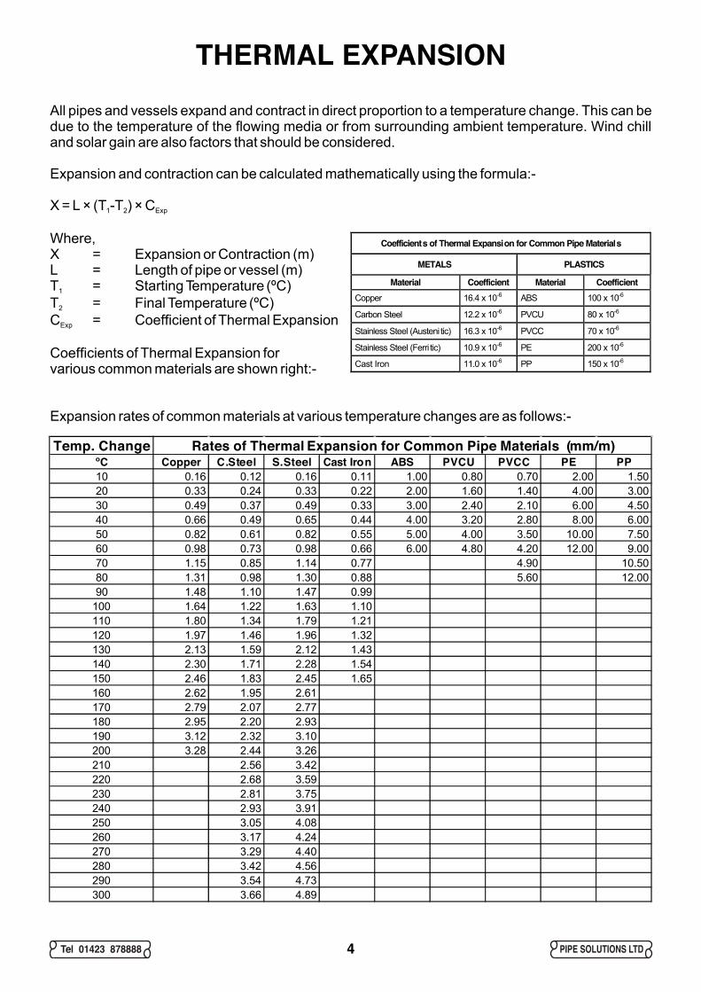
THERMAL EXPANSIONAll pipes and vessels expand and contract in direct proportion to a temperature change. This can be due to the temperature of the flowing media or from surrounding ambient temperature. Wind chill and solar gain are also factors that should be considered.
Expansion and contraction can be calculated mathematically using the formula:-
X = L × (T -T ) × C1 2 Exp
Where,X = Expansion or Contraction (m)L = Length of pipe or vessel (m)T = Starting Temperature (ºC)1
T = Final Temperature (ºC)2
C = Coefficient of Thermal ExpansionExp
Coefficients of Thermal Expansion forvarious common materials are shown right:-
4
Coefficients of Thermal Expansion for Common Pipe Materials
METALS PLASTICS
Material Coefficient Material Coefficient Copper 16.4 x 10⁻⁶ ABS 100 x 10-6
Carbon Steel 12.2 x 10⁻⁶ PVCU 80 x 10-6
Stainless Steel (Austeni tic) 16.3 x 10⁻⁶ PVCC 70 x 10-6
Stainless Steel (Ferri tic) 10.9 x 10⁻⁶ PE 200 x 10-6
Cast Iron 11.0 x 10⁻⁶ PP 150 x 10-6
Expansion rates of common materials at various temperature changes are as follows:-
Temp. Change Rates of Thermal Expansion for Common Pipe Materials (mm/m)ºC Copper C.Steel S.Steel Cast Iron ABS PVCU PVCC PE PP10 0.16 0.12 0.16 0.11 1.00 0.80 0.70 2.00 1.5020 0.33 0.24 0.33 0.22 2.00 1.60 1.40 4.00 3.0030 0.49 0.37 0.49 0.33 3.00 2.40 2.10 6.00 4.5040 0.66 0.49 0.65 0.44 4.00 3.20 2.80 8.00 6.0050 0.82 0.61 0.82 0.55 5.00 4.00 3.50 10.00 7.5060 0.98 0.73 0.98 0.66 6.00 4.80 4.20 12.00 9.0070 1.15 0.85 1.14 0.77 4.90 10.5080 1.31 0.98 1.30 0.88 5.60 12.0090 1.48 1.10 1.47 0.99
100 1.64 1.22 1.63 1.10110 1.80 1.34 1.79 1.21120 1.97 1.46 1.96 1.32130 2.13 1.59 2.12 1.43140 2.30 1.71 2.28 1.54150 2.46 1.83 2.45 1.65160 2.62 1.95 2.61170 2.79 2.07 2.77180 2.95 2.20 2.93190 3.12 2.32 3.10200 3.28 2.44 3.26210 2.56 3.42220 2.68 3.59230 2.81 3.75240 2.93 3.91250 3.05 4.08260 3.17 4.24270 3.29 4.40280 3.42 4.56290 3.54 4.73300 3.66 4.89
Tel 01423 878888 PIPE SOLUTIONS LTD
PROBLEMS TO OVERCOMEExceeding Allowable StressesWhen the pipe is free to move, problems tend not to exist so often. However, when the pipe is restricted from moving freely, large forces and moments are imposed on pipe supports, anchors and connections to vessels, plant, etc. As a result, the allowable stress on the pipe and the fixed points may well be exceeded, leading to premature failure.
Pipe Bowing and BucklingOther expansion related problems may also start to occur, such as the pipe buckling or bowing. This is often the direct result of a pipe growing in length between two fixed points. Although the fixed points (anchors) may not be over-stressed and remain intact, the pipe is being compressed like a column and could potentially buckle.
Building Settlement Movement Whenever pipes are routed across structural movement joints in buildings, roads, bridges, etc., they will be subjected to differential displacements. These must be taken into consideration when designing the pipe system.
Vessel SettlementPipes may be installed with rigid connections to vessels used for storage of fluids. These installations will probably be made whilst the vessel is empty. However, when the vessel is filled, the weight of the fluid may cause settlement of the foundations or compression of spring mountings. These must be taken into consideration when designing the pipe system.
Plant Vibration and Start-upWhenever equipment that is installed on anti-vibration mountings starts-up or runs-down, it will pass through the resonant frequency of the vibration isolation system. At this point, the equipment will move more than during normal operating conditions. These movements or displacements will be imposed on the pipework connections and may overstress or fatigue the pipe and or plant nozzles. Expansion bellows can relieve these stresses and also reduce the transmission of noise and vibration to the pipe system.
Water Hammer and Flow Induced Movement and VibrationTurbulent and high velocity flow of liquids in pipes can cause pipe displacements where the liquid acts upon direction changes and reductions in the pipe system. Where a system process uses automated valves, fast closure times can cause water hammer. Expansion bellows and flexible hoses can help with relieving stresses in the pipe.
Wind Loading on Supporting StructuresHigh wind speeds naturally buffer buildings, bridges, gantries, etc. The forces developed may cause the structure to sway, which will in turn displace the pipework. If there is a possibility of displacements being imposed on the pipe, then they must be taken into consideration when designing the pipe system.
Seismic LoadingAlthough rare in the UK, consider pipe displacements due to seismic activity. Careful analysis is required with due allowance for pipe shock absorbers and sway braces.
5Tel 01423 878888 PIPE SOLUTIONS LTD

NATURAL PIPE FLEXING
METHODICAL APPROACHThere is no such thing as a "correct solution" as many can exist. However taking a methodical approach will unveil the possible solutions that can solve the expansion problems.
Many factors must be taken into consideration. The following information should be gathered before different methods are considered:-
Pipe Material (Expansion Coefficients)Pipe Nominal Size (and Gauge, Wall Thickness or Schedule)Pipe Length, Location and LayoutTemperature (Minimum, Maximum and Starting Temperature)Pressure (Working and Test)Connection and Branch PointsBuilding Structure (Position and Strength of Walls, Floors, Soffits, Mezzanines, etc)
ANCHORS
CHECK THEPOSITIONS AND STRENGTHS OF
UNRESTRAINED BELLOWSSTANDARD AXIAL EXTERNALLY PRESSURISED AXIAL
RESTRAINED BELLOWS
PRESSURE BALANCEDBELLOWS
CONTACTPIPE SOLUTIONS LTD
LATERAL HINGED GIMBAL
GUIDES
SUPPORTS
PIPELENGTH
PIPE LOOPS
PLANT VIBRATION
COEFFICIENT OF EXPANSION
L-SHAPED LAYOUTS
PIPEMATERIAL
BUILDING SETTLEMENT
TEMPERATURE CHANGE
Z-SHAPED LAYOUTS
VESSEL SETTLEMENT
PIPE EXPANSION
WIND LOAD MOVEMENT
WATER HAMMER
ESTABLISH PIPE MOVEMENT
DETERMINE EXPANSION
CONSIDERALSO
PIPE SYSTEMLAYOUT & LOCATION
CONSIDER THE VARIOUS SOLUTIONS IN TURN
SOLUTIONFOUND
x
x
&
&
= &
&
NO
NO
YES
NO
Tel 01423 878888 PIPE SOLUTIONS LTD6
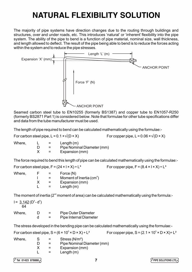
NATURAL FLEXIBILITY SOLUTIONThe majority of pipe systems have direction changes due to the routing through buildings and structures, over and under roads, etc. This introduces ‘natural’ or ‘inherent’ flexibility into the pipe system. The ability of the pipe to bend is a function of pipe material, nominal size, wall thickness, and length allowed to deflect. The result of the pipe being able to bend is to reduce the forces acting within the system and to reduce the pipe stresses.
Seamed carbon steel tube to EN10255 (formerly BS1387) and copper tube to EN1057-R250 (formerly BS2871 Part 1) is considered below. Note that formulae for other tube specifications differ and data from the tube manufacturer must be used.
The length of pipe required to bend can be calculated mathematically using the formulae:-
For carbon steel pipe, L = 0.1 × (D × X) For copper pipe, L = 0.06 × (D × X)
Where, L = Length (m)D = Pipe Nominal Diameter (mm)X = Expansion (mm)
The force required to bend this length of pipe can be calculated mathematically using the formulae:-
For carbon steel pipe, F = (24 × I × X) ÷ L³ For copper pipe, F = (8.4 × I × X) ÷ L³
Where, F = Force (N)4I = Moment of Inertia (cm )
X = Expansion (mm)L = Length (m)
ndThe moment of inertia (2 moment of area) can be calculated mathematically using the formula:-4 4I = 3.142 (D - d )
64
Where, D = Pipe Outer Diameterd = Pipe Internal Diameter
The stress developed in the bending pipe can be calculated mathematically using the formulae:-5 5For carbon steel pipe, S = (6 × 10 × D × X) ÷ L² For copper pipe, S = (2.1 × 10 × D × X)÷ L²
Where, S = Stress (N/m²)D = Pipe Nominal Diameter (mm)X = Expansion (mm)L = Length (m)
Ö Ö
Tel 01423 878888 PIPE SOLUTIONS LTD
Expansion ‘X’ (mm)
Force ‘F’ (N)
ANCHOR POINT
ANCHOR POINT
Length ‘L’ (m)
7
Tel 01423 878888 PIPE SOLUTIONS LTD
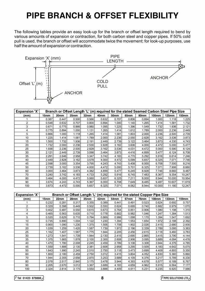
PIPE BRANCH & OFFSET FLEXIBILITYThe following tables provide an easy look-up for the branch or offset length required to bend by various amounts of expansion or contraction, for both carbon steel and copper pipes. If 50% cold pull is used, the branch or offset will accommodate twice the movement; for look-up purposes, use half the amount of expansion or contraction.
ANCHOR
ANCHOR
COLDPULLOffset ‘L’ (m)
PIPELENGTH
Expansion ‘X’ (mm)
Expansion 'X' Branch or Offset Length 'L' (m) required for the stated Seamed Carbon Steel Pipe Size(mm) 15mm 20mm 25mm 32mm 40mm 50mm 65mm 80mm 100mm 125mm 150mm
1 0.387 0.447 0.500 0.566 0.632 0.707 0.806 0.894 1.000 1.118 1.2252 0.548 0.632 0.707 0.800 0.894 1.000 1.140 1.265 1.414 1.581 1.7323 0.671 0.775 0.866 0.980 1.095 1.225 1.396 1.549 1.732 1.936 2.1214 0.775 0.894 1.000 1.131 1.265 1.414 1.612 1.789 2.000 2.236 2.4495 0.866 1.000 1.118 1.265 1.414 1.581 1.803 2.000 2.236 2.500 2.739
10 1.225 1.414 1.581 1.789 2.000 2.236 2.550 2.828 3.162 3.536 3.87315 1.500 1.732 1.936 2.191 2.449 2.739 3.122 3.464 3.873 4.330 4.74320 1.732 2.000 2.236 2.530 2.828 3.162 3.606 4.000 4.472 5.000 5.47725 1.936 2.236 2.500 2.828 3.162 3.536 4.031 4.472 5.000 5.590 6.12430 2.121 2.449 2.739 3.098 3.464 3.873 4.416 4.899 5.477 6.124 6.70835 2.291 2.646 2.958 3.347 3.742 4.183 4.770 5.292 5.916 6.614 7.24640 2.449 2.828 3.162 3.578 4.000 4.472 5.099 5.657 6.325 7.071 7.74645 2.598 3.000 3.354 3.795 4.243 4.743 5.408 6.000 6.708 7.500 8.21650 2.739 3.162 3.536 4.000 4.472 5.000 5.701 6.325 7.071 7.906 8.66060 3.000 3.464 3.873 4.382 4.899 5.477 6.245 6.928 7.746 8.660 9.48770 3.240 3.742 4.183 4.733 5.292 5.916 6.745 7.483 8.367 9.354 10.24780 3.464 4.000 4.472 5.060 5.657 6.325 7.211 8.000 8.944 10.000 10.95490 3.674 4.243 4.743 5.367 6.000 6.708 7.649 8.485 9.487 10.607 11.619100 3.873 4.472 5.000 5.657 6.325 7.071 8.062 8.944 10.000 11.180 12.247
8
Expansion 'X' Branch or Offset Length 'L' (m) required for the stated Copper Pipe Size (mm) 15mm 22mm 28mm 35mm 42mm 54mm 67mm 76mm 108mm 133mm 159mm
1 0.232 0.281 0.317 0.355 0.389 0.441 0.491 0.523 0.624 0.692 0.7572 0.329 0.398 0.449 0.502 0.550 0.624 0.695 0.740 0.882 0.979 1.0703 0.402 0.487 0.550 0.615 0.673 0.764 0.851 0.906 1.080 1.198 1.3104 0.465 0.563 0.635 0.710 0.778 0.882 0.982 1.046 1.247 1.384 1.5135 0.520 0.629 0.710 0.794 0.869 0.986 1.098 1.170 1.394 1.547 1.692
10 0.735 0.890 1.004 1.122 1.230 1.394 1.553 1.654 1.972 2.188 2.39215 0.900 1.090 1.230 1.375 1.506 1.708 1.902 2.026 2.415 2.680 2.93020 1.039 1.259 1.420 1.587 1.739 1.972 2.196 2.339 2.789 3.095 3.38325 1.162 1.407 1.587 1.775 1.944 2.205 2.456 2.615 3.118 3.460 3.78330 1.273 1.541 1.739 1.944 2.130 2.415 2.690 2.865 3.415 3.790 4.14435 1.375 1.665 1.878 2.100 2.300 2.608 2.906 3.095 3.689 4.094 4.47640 1.470 1.780 2.008 2.245 2.459 2.789 3.106 3.308 3.944 4.376 4.78545 1.559 1.888 2.130 2.381 2.608 2.958 3.295 3.509 4.183 4.642 5.07550 1.643 1.990 2.245 2.510 2.750 3.118 3.473 3.699 4.409 4.893 5.35060 1.800 2.180 2.459 2.750 3.012 3.415 3.804 4.052 4.830 5.360 5.86070 1.944 2.355 2.656 2.970 3.253 3.689 4.109 4.376 5.217 5.789 6.33080 2.078 2.517 2.840 3.175 3.478 3.944 4.393 4.678 5.577 6.189 6.76790 2.205 2.670 3.012 3.367 3.689 4.183 4.659 4.962 5.915 6.564 7.177100 2.324 2.814 3.175 3.550 3.888 4.409 4.911 5.231 6.235 6.920 7.566
Tel 01423 878888 PIPE SOLUTIONS LTD
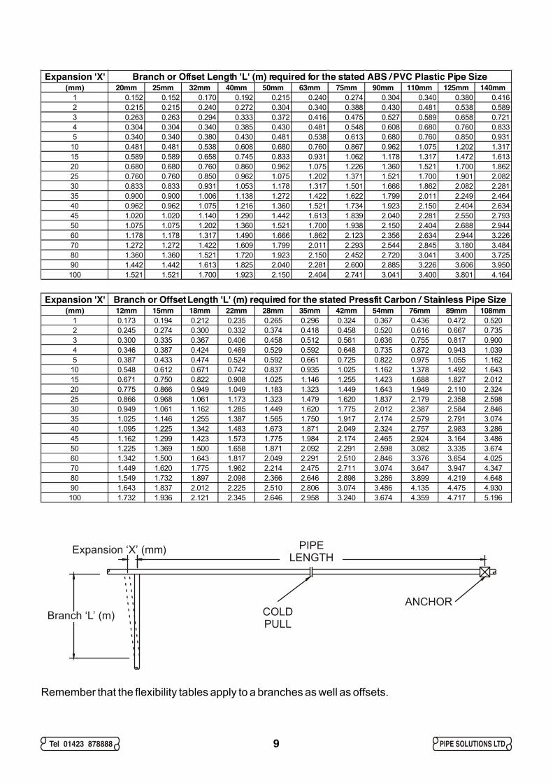
Expansion 'X' Branch or Offset Length 'L' (m) required for the stated ABS / PVC Plastic Pipe Size(mm) 20mm 25mm 32mm 40mm 50mm 63mm 75mm 90mm 110mm 125mm 140mm
1 0.152 0.152 0.170 0.192 0.215 0.240 0.274 0.304 0.340 0.380 0.4162 0.215 0.215 0.240 0.272 0.304 0.340 0.388 0.430 0.481 0.538 0.5893 0.263 0.263 0.294 0.333 0.372 0.416 0.475 0.527 0.589 0.658 0.7214 0.304 0.304 0.340 0.385 0.430 0.481 0.548 0.608 0.680 0.760 0.8335 0.340 0.340 0.380 0.430 0.481 0.538 0.613 0.680 0.760 0.850 0.931
10 0.481 0.481 0.538 0.608 0.680 0.760 0.867 0.962 1.075 1.202 1.31715 0.589 0.589 0.658 0.745 0.833 0.931 1.062 1.178 1.317 1.472 1.61320 0.680 0.680 0.760 0.860 0.962 1.075 1.226 1.360 1.521 1.700 1.86225 0.760 0.760 0.850 0.962 1.075 1.202 1.371 1.521 1.700 1.901 2.08230 0.833 0.833 0.931 1.053 1.178 1.317 1.501 1.666 1.862 2.082 2.28135 0.900 0.900 1.006 1.138 1.272 1.422 1.622 1.799 2.011 2.249 2.46440 0.962 0.962 1.075 1.216 1.360 1.521 1.734 1.923 2.150 2.404 2.63445 1.020 1.020 1.140 1.290 1.442 1.613 1.839 2.040 2.281 2.550 2.79350 1.075 1.075 1.202 1.360 1.521 1.700 1.938 2.150 2.404 2.688 2.94460 1.178 1.178 1.317 1.490 1.666 1.862 2.123 2.356 2.634 2.944 3.22670 1.272 1.272 1.422 1.609 1.799 2.011 2.293 2.544 2.845 3.180 3.48480 1.360 1.360 1.521 1.720 1.923 2.150 2.452 2.720 3.041 3.400 3.72590 1.442 1.442 1.613 1.825 2.040 2.281 2.600 2.885 3.226 3.606 3.950100 1.521 1.521 1.700 1.923 2.150 2.404 2.741 3.041 3.400 3.801 4.164
9
ANCHORCOLDPULL
Branch ‘L’ (m)
PIPELENGTH
Expansion ‘X’ (mm)
Remember that the flexibility tables apply to a branches as well as offsets.
Expansion 'X' Branch or Offset Length 'L' (m) required for the stated Pressfit Carbon / Stainless Pipe Size(mm) 12mm 15mm 18mm 22mm 28mm 35mm 42mm 54mm 76mm 89mm 108mm
1 0.173 0.194 0.212 0.235 0.265 0.296 0.324 0.367 0.436 0.472 0.5202 0.245 0.274 0.300 0.332 0.374 0.418 0.458 0.520 0.616 0.667 0.7353 0.300 0.335 0.367 0.406 0.458 0.512 0.561 0.636 0.755 0.817 0.9004 0.346 0.387 0.424 0.469 0.529 0.592 0.648 0.735 0.872 0.943 1.0395 0.387 0.433 0.474 0.524 0.592 0.661 0.725 0.822 0.975 1.055 1.162
10 0.548 0.612 0.671 0.742 0.837 0.935 1.025 1.162 1.378 1.492 1.64315 0.671 0.750 0.822 0.908 1.025 1.146 1.255 1.423 1.688 1.827 2.01220 0.775 0.866 0.949 1.049 1.183 1.323 1.449 1.643 1.949 2.110 2.32425 0.866 0.968 1.061 1.173 1.323 1.479 1.620 1.837 2.179 2.358 2.59830 0.949 1.061 1.162 1.285 1.449 1.620 1.775 2.012 2.387 2.584 2.84635 1.025 1.146 1.255 1.387 1.565 1.750 1.917 2.174 2.579 2.791 3.07440 1.095 1.225 1.342 1.483 1.673 1.871 2.049 2.324 2.757 2.983 3.28645 1.162 1.299 1.423 1.573 1.775 1.984 2.174 2.465 2.924 3.164 3.48650 1.225 1.369 1.500 1.658 1.871 2.092 2.291 2.598 3.082 3.335 3.67460 1.342 1.500 1.643 1.817 2.049 2.291 2.510 2.846 3.376 3.654 4.02570 1.449 1.620 1.775 1.962 2.214 2.475 2.711 3.074 3.647 3.947 4.34780 1.549 1.732 1.897 2.098 2.366 2.646 2.898 3.286 3.899 4.219 4.64890 1.643 1.837 2.012 2.225 2.510 2.806 3.074 3.486 4.135 4.475 4.930100 1.732 1.936 2.121 2.345 2.646 2.958 3.240 3.674 4.359 4.717 5.196
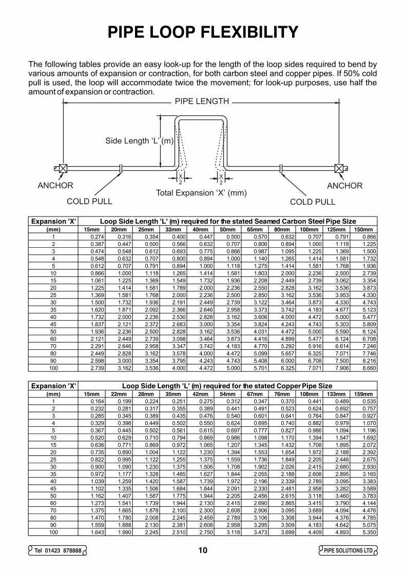
Expansion 'X' Loop Side Length 'L' (m) required for the stated Seamed Carbon Steel Pipe Size (mm) 15mm 20mm 25mm 32mm 40mm 50mm 65mm 80mm 100mm 125mm 150mm
1 0.274 0.316 0.354 0.400 0.447 0.500 0.570 0.632 0.707 0.791 0.8662 0.387 0.447 0.500 0.566 0.632 0.707 0.806 0.894 1.000 1.118 1.2253 0.474 0.548 0.612 0.693 0.775 0.866 0.987 1.095 1.225 1.369 1.5004 0.548 0.632 0.707 0.800 0.894 1.000 1.140 1.265 1.414 1.581 1.7325 0.612 0.707 0.791 0.894 1.000 1.118 1.275 1.414 1.581 1.768 1.936
10 0.866 1.000 1.118 1.265 1.414 1.581 1.803 2.000 2.236 2.500 2.73915 1.061 1.225 1.369 1.549 1.732 1.936 2.208 2.449 2.739 3.062 3.35420 1.225 1.414 1.581 1.789 2.000 2.236 2.550 2.828 3.162 3.536 3.87325 1.369 1.581 1.768 2.000 2.236 2.500 2.850 3.162 3.536 3.953 4.33030 1.500 1.732 1.936 2.191 2.449 2.739 3.122 3.464 3.873 4.330 4.74335 1.620 1.871 2.092 2.366 2.646 2.958 3.373 3.742 4.183 4.677 5.12340 1.732 2.000 2.236 2.530 2.828 3.162 3.606 4.000 4.472 5.000 5.47745 1.837 2.121 2.372 2.683 3.000 3.354 3.824 4.243 4.743 5.303 5.80950 1.936 2.236 2.500 2.828 3.162 3.536 4.031 4.472 5.000 5.590 6.12460 2.121 2.449 2.739 3.098 3.464 3.873 4.416 4.899 5.477 6.124 6.70870 2.291 2.646 2.958 3.347 3.742 4.183 4.770 5.292 5.916 6.614 7.24680 2.449 2.828 3.162 3.578 4.000 4.472 5.099 5.657 6.325 7.071 7.74690 2.598 3.000 3.354 3.795 4.243 4.743 5.408 6.000 6.708 7.500 8.216100 2.739 3.162 3.536 4.000 4.472 5.000 5.701 6.325 7.071 7.906 8.660
Tel 01423 878888 PIPE SOLUTIONS LTD
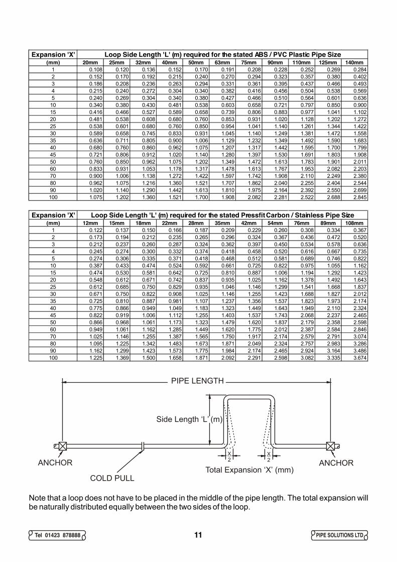
PIPE LOOP FLEXIBILITYThe following tables provide an easy look-up for the length of the loop sides required to bend by various amounts of expansion or contraction, for both carbon steel and copper pipes. If 50% cold pull is used, the loop will accommodate twice the movement; for look-up purposes, use half the amount of expansion or contraction.
Expansion 'X' Loop Side Length 'L' (m) required for the stated Copper Pipe Size (mm) 15mm 22mm 28mm 35mm 42mm 54mm 67mm 76mm 108mm 133mm 159mm
1 0.164 0.199 0.224 0.251 0.275 0.312 0.347 0.370 0.441 0.489 0.5352 0.232 0.281 0.317 0.355 0.389 0.441 0.491 0.523 0.624 0.692 0.7573 0.285 0.345 0.389 0.435 0.476 0.540 0.601 0.641 0.764 0.847 0.9274 0.329 0.398 0.449 0.502 0.550 0.624 0.695 0.740 0.882 0.979 1.0705 0.367 0.445 0.502 0.561 0.615 0.697 0.777 0.827 0.986 1.094 1.196
10 0.520 0.629 0.710 0.794 0.869 0.986 1.098 1.170 1.394 1.547 1.69215 0.636 0.771 0.869 0.972 1.065 1.207 1.345 1.432 1.708 1.895 2.07220 0.735 0.890 1.004 1.122 1.230 1.394 1.553 1.654 1.972 2.188 2.39225 0.822 0.995 1.122 1.255 1.375 1.559 1.736 1.849 2.205 2.446 2.67530 0.900 1.090 1.230 1.375 1.506 1.708 1.902 2.026 2.415 2.680 2.93035 0.972 1.177 1.328 1.485 1.627 1.844 2.055 2.188 2.608 2.895 3.16540 1.039 1.259 1.420 1.587 1.739 1.972 2.196 2.339 2.789 3.095 3.38345 1.102 1.335 1.506 1.684 1.844 2.091 2.330 2.481 2.958 3.282 3.58950 1.162 1.407 1.587 1.775 1.944 2.205 2.456 2.615 3.118 3.460 3.78360 1.273 1.541 1.739 1.944 2.130 2.415 2.690 2.865 3.415 3.790 4.14470 1.375 1.665 1.878 2.100 2.300 2.608 2.906 3.095 3.689 4.094 4.47680 1.470 1.780 2.008 2.245 2.459 2.789 3.106 3.308 3.944 4.376 4.78590 1.559 1.888 2.130 2.381 2.608 2.958 3.295 3.509 4.183 4.642 5.075100 1.643 1.990 2.245 2.510 2.750 3.118 3.473 3.699 4.409 4.893 5.350
ANCHORANCHOR
COLD PULLCOLD PULL
Side Length ‘L’ (m)
PIPE LENGTH
Total Expansion ‘X’ (mm)
X2
X2
10
Tel 01423 878888 PIPE SOLUTIONS LTD11
Expansion 'X' Loop Side Length 'L' (m) required for the stated Pressfit Carbon / Stainless Pipe Size(mm) 12mm 15mm 18mm 22mm 28mm 35mm 42mm 54mm 76mm 89mm 108mm
1 0.122 0.137 0.150 0.166 0.187 0.209 0.229 0.260 0.308 0.334 0.3672 0.173 0.194 0.212 0.235 0.265 0.296 0.324 0.367 0.436 0.472 0.5203 0.212 0.237 0.260 0.287 0.324 0.362 0.397 0.450 0.534 0.578 0.6364 0.245 0.274 0.300 0.332 0.374 0.418 0.458 0.520 0.616 0.667 0.7355 0.274 0.306 0.335 0.371 0.418 0.468 0.512 0.581 0.689 0.746 0.822
10 0.387 0.433 0.474 0.524 0.592 0.661 0.725 0.822 0.975 1.055 1.16215 0.474 0.530 0.581 0.642 0.725 0.810 0.887 1.006 1.194 1.292 1.42320 0.548 0.612 0.671 0.742 0.837 0.935 1.025 1.162 1.378 1.492 1.64325 0.612 0.685 0.750 0.829 0.935 1.046 1.146 1.299 1.541 1.668 1.83730 0.671 0.750 0.822 0.908 1.025 1.146 1.255 1.423 1.688 1.827 2.01235 0.725 0.810 0.887 0.981 1.107 1.237 1.356 1.537 1.823 1.973 2.17440 0.775 0.866 0.949 1.049 1.183 1.323 1.449 1.643 1.949 2.110 2.32445 0.822 0.919 1.006 1.112 1.255 1.403 1.537 1.743 2.068 2.237 2.46550 0.866 0.968 1.061 1.173 1.323 1.479 1.620 1.837 2.179 2.358 2.59860 0.949 1.061 1.162 1.285 1.449 1.620 1.775 2.012 2.387 2.584 2.84670 1.025 1.146 1.255 1.387 1.565 1.750 1.917 2.174 2.579 2.791 3.07480 1.095 1.225 1.342 1.483 1.673 1.871 2.049 2.324 2.757 2.983 3.28690 1.162 1.299 1.423 1.573 1.775 1.984 2.174 2.465 2.924 3.164 3.486100 1.225 1.369 1.500 1.658 1.871 2.092 2.291 2.598 3.082 3.335 3.674
Expansion 'X' Loop Side Length 'L' (m) required for the stated ABS / PVC Plastic Pipe Size (mm) 20mm 25mm 32mm 40mm 50mm 63mm 75mm 90mm 110mm 125mm 140mm
1 0.108 0.120 0.136 0.152 0.170 0.191 0.208 0.228 0.252 0.269 0.2842 0.152 0.170 0.192 0.215 0.240 0.270 0.294 0.323 0.357 0.380 0.4023 0.186 0.208 0.236 0.263 0.294 0.331 0.361 0.395 0.437 0.466 0.4934 0.215 0.240 0.272 0.304 0.340 0.382 0.416 0.456 0.504 0.538 0.5695 0.240 0.269 0.304 0.340 0.380 0.427 0.466 0.510 0.564 0.601 0.636
10 0.340 0.380 0.430 0.481 0.538 0.603 0.658 0.721 0.797 0.850 0.90015 0.416 0.466 0.527 0.589 0.658 0.739 0.806 0.883 0.977 1.041 1.10220 0.481 0.538 0.608 0.680 0.760 0.853 0.931 1.020 1.128 1.202 1.27225 0.538 0.601 0.680 0.760 0.850 0.954 1.041 1.140 1.261 1.344 1.42230 0.589 0.658 0.745 0.833 0.931 1.045 1.140 1.249 1.381 1.472 1.55835 0.636 0.711 0.805 0.900 1.006 1.129 1.232 1.349 1.492 1.590 1.68340 0.680 0.760 0.860 0.962 1.075 1.207 1.317 1.442 1.595 1.700 1.79945 0.721 0.806 0.912 1.020 1.140 1.280 1.397 1.530 1.691 1.803 1.90850 0.760 0.850 0.962 1.075 1.202 1.349 1.472 1.613 1.783 1.901 2.01160 0.833 0.931 1.053 1.178 1.317 1.478 1.613 1.767 1.953 2.082 2.20370 0.900 1.006 1.138 1.272 1.422 1.597 1.742 1.908 2.110 2.249 2.38080 0.962 1.075 1.216 1.360 1.521 1.707 1.862 2.040 2.255 2.404 2.54490 1.020 1.140 1.290 1.442 1.613 1.810 1.975 2.164 2.392 2.550 2.699100 1.075 1.202 1.360 1.521 1.700 1.908 2.082 2.281 2.522 2.688 2.845
ANCHORANCHOR
COLD PULL
Side Length ‘L’ (m)
PIPE LENGTH
Total Expansion ‘X’ (mm)
X2
X2
Note that a loop does not have to be placed in the middle of the pipe length. The total expansion will be naturally distributed equally between the two sides of the loop.
Tel 01423 878888 PIPE SOLUTIONS LTD
EXPANSION JOINT SOLUTIONIf natural flexibility is insufficient, or the resultant forces are excessive, then expansion joints are the next solution. However, there are several different models and it must be decided which is the best for the pipe system being designed.
The possible positions and strengths of anchors and guides must be considered. Different models of expansion joint, when combined with the pipe system parameters, will impose different forces.
The expansion joints can be divided into two main groups. These are ‘unrestrained’ and ‘restrained’ expansion joints. All expansion joints fall into one of these groups as illustrated below:-
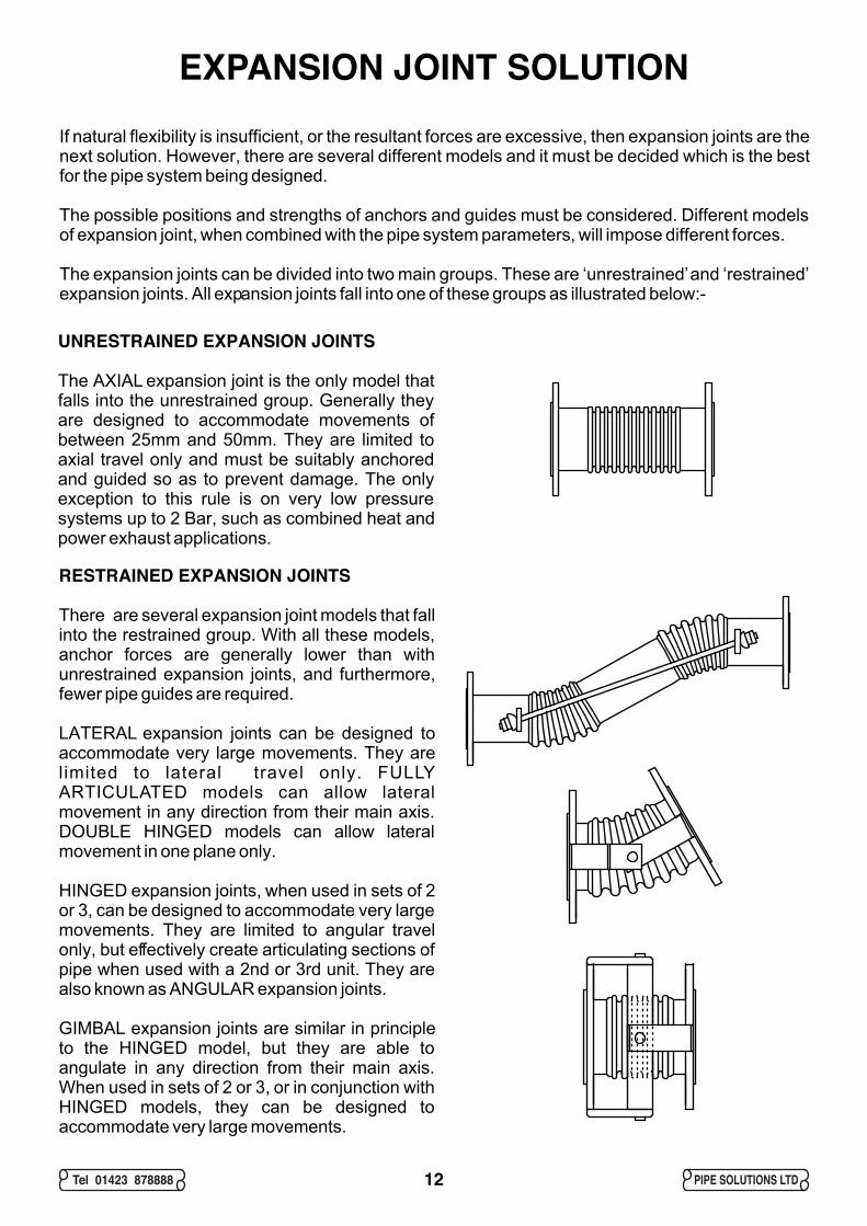
UNRESTRAINED EXPANSION JOINTS
The AXIAL expansion joint is the only model that falls into the unrestrained group. Generally they are designed to accommodate movements of between 25mm and 50mm. They are limited to axial travel only and must be suitably anchored and guided so as to prevent damage. The only exception to this rule is on very low pressure systems up to 2 Bar, such as combined heat and power exhaust applications.
RESTRAINED EXPANSION JOINTS
There are several expansion joint models that fall into the restrained group. With all these models, anchor forces are generally lower than with unrestrained expansion joints, and furthermore, fewer pipe guides are required.
LATERAL expansion joints can be designed to accommodate very large movements. They are limited to lateral travel only. FULLY ARTICULATED models can allow lateral movement in any direction from their main axis. DOUBLE HINGED models can allow lateral movement in one plane only.
HINGED expansion joints, when used in sets of 2 or 3, can be designed to accommodate very large movements. They are limited to angular travel only, but effectively create articulating sections of pipe when used with a 2nd or 3rd unit. They are also known as ANGULAR expansion joints.
GIMBAL expansion joints are similar in principle to the HINGED model, but they are able to angulate in any direction from their main axis. When used in sets of 2 or 3, or in conjunction with HINGED models, they can be designed to accommodate very large movements.
12
Tel 01423 878888 PIPE SOLUTIONS LTD
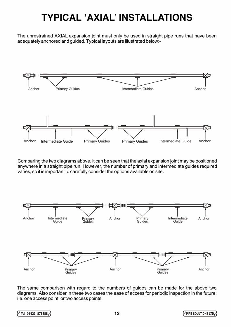
TYPICAL ‘AXIAL’ INSTALLATIONSThe unrestrained AXIAL expansion joint must only be used in straight pipe runs that have been adequately anchored and guided. Typical layouts are illustrated below:-
Comparing the two diagrams above, it can be seen that the axial expansion joint may be positioned anywhere in a straight pipe run. However, the number of primary and intermediate guides required varies, so it is important to carefully consider the options available on site.
The same comparison with regard to the numbers of guides can be made for the above two diagrams. Also consider in these two cases the ease of access for periodic inspection in the future; i.e. one access point, or two access points.
Anchor AnchorPrimary Guides Intermediate Guides
Anchor AnchorAnchor PrimaryGuides
PrimaryGuides
IntermediateGuide
IntermediateGuide
Anchor AnchorAnchor PrimaryGuides
PrimaryGuides
Intermediate GuideAnchor AnchorIntermediate GuidePrimary GuidesPrimary Guides
13
Tel 01423 878888 PIPE SOLUTIONS LTD
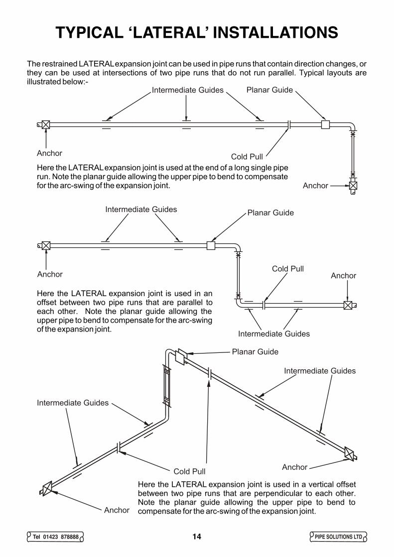
TYPICAL ‘LATERAL’ INSTALLATIONSThe restrained LATERAL expansion joint can be used in pipe runs that contain direction changes, or they can be used at intersections of two pipe runs that do not run parallel. Typical layouts are illustrated below:-
Here the LATERAL expansion joint is used at the end of a long single pipe run. Note the planar guide allowing the upper pipe to bend to compensate for the arc-swing of the expansion joint.
Here the LATERAL expansion joint is used in an offset between two pipe runs that are parallel to each other. Note the planar guide allowing the upper pipe to bend to compensate for the arc-swing of the expansion joint.
Here the LATERAL expansion joint is used in a vertical offset between two pipe runs that are perpendicular to each other. Note the planar guide allowing the upper pipe to bend to compensate for the arc-swing of the expansion joint.
Anchor
Anchor Cold Pull
Planar GuideIntermediate Guides
AnchorAnchorCold Pull
Planar GuideIntermediate Guides
Intermediate Guides
Intermediate Guides
Intermediate Guides
Cold Pull
Planar Guide
Anchor
Anchor
14
Tel 01423 878888 PIPE SOLUTIONS LTD
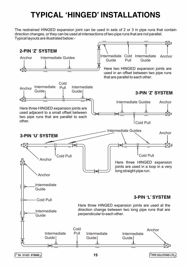
TYPICAL ‘HINGED’ INSTALLATIONSThe restrained HINGED expansion joint can be used in sets of 2 or 3 in pipe runs that contain direction changes, or they can be used at intersections of two pipe runs that are not parallel. Typical layouts are illustrated below:-
Here two HINGED expansion joints are used in an offset between two pipe runs that are parallel to each other.
Here three HINGED expansion joints are used adjacent to a small offset between two pipe runs that are parallel to each other.
Here three HINGED expansion joints are used in a loop in a very long straight pipe run.
Intermediate Guides
Cold PullCold PullAnchor
Anchor
Intermediate Guides
IntermediateGuide
IntermediateGuide
ColdPull
Cold Pull
Anchor
Anchor
Intermediate Guides IntermediateGuide
IntermediateGuide
ColdPull
AnchorAnchor
IntermediateGuide
IntermediateGuide
ColdPull
IntermediateGuide
IntermediateGuide
IntermediateGuide
Cold Pull
Anchor
Anchor
Here three HINGED expansion joints are used at the direction change between two long pipe runs that are perpendicular to each other.
2-PIN ‘Z’ SYSTEM
3-PIN ‘Z’ SYSTEM
3-PIN ‘U’ SYSTEM
3-PIN ‘L’ SYSTEM
15
Tel 01423 878888 PIPE SOLUTIONS LTD
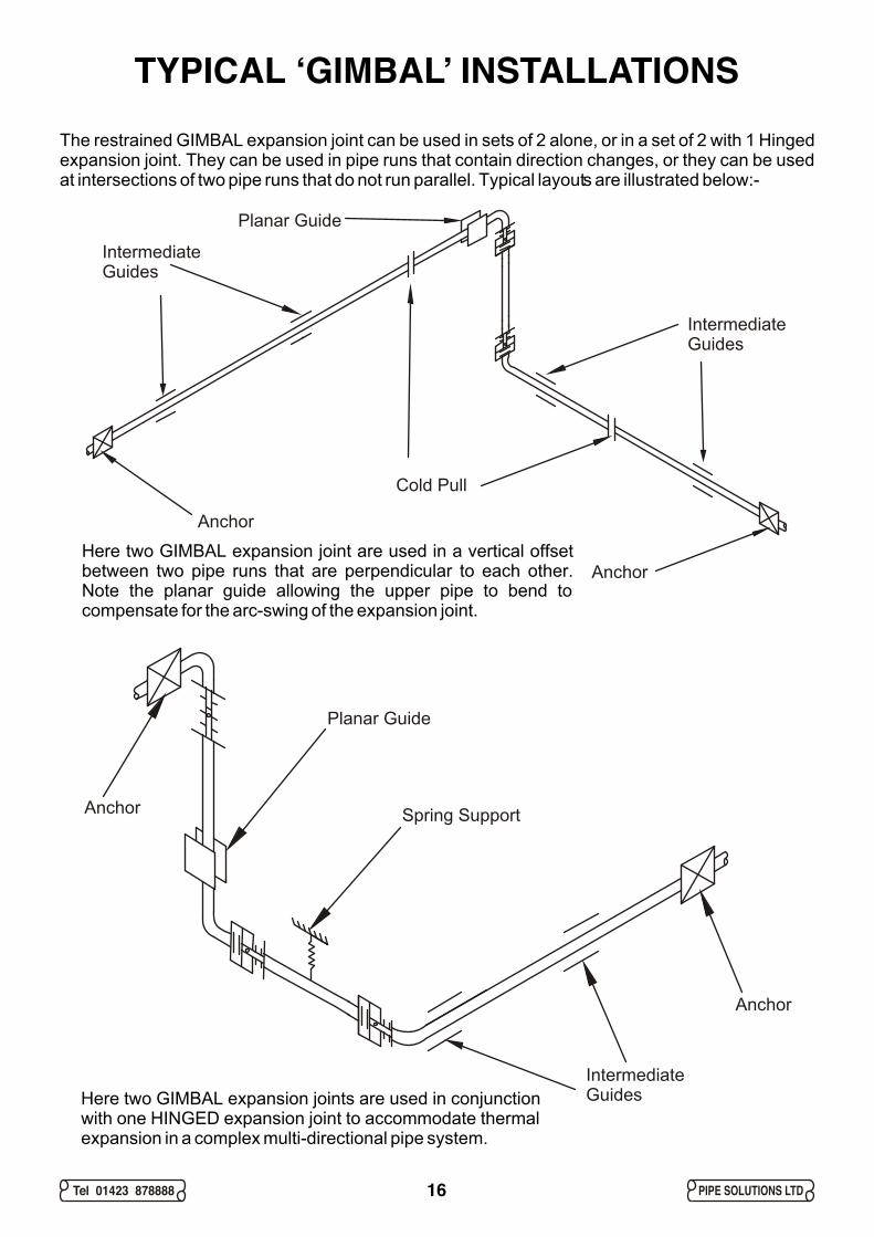
TYPICAL ‘GIMBAL’ INSTALLATIONSThe restrained GIMBAL expansion joint can be used in sets of 2 alone, or in a set of 2 with 1 Hinged expansion joint. They can be used in pipe runs that contain direction changes, or they can be used at intersections of two pipe runs that do not run parallel. Typical layouts are illustrated below:-
Anchor
Anchor
Cold Pull
IntermediateGuides
IntermediateGuides
Planar Guide
Anchor
Anchor
Spring Support
IntermediateGuides
Planar Guide
Here two GIMBAL expansion joints are used in conjunction with one HINGED expansion joint to accommodate thermal expansion in a complex multi-directional pipe system.
Here two GIMBAL expansion joint are used in a vertical offset between two pipe runs that are perpendicular to each other. Note the planar guide allowing the upper pipe to bend to compensate for the arc-swing of the expansion joint.
16
Tel 01423 878888 PIPE SOLUTIONS LTD17
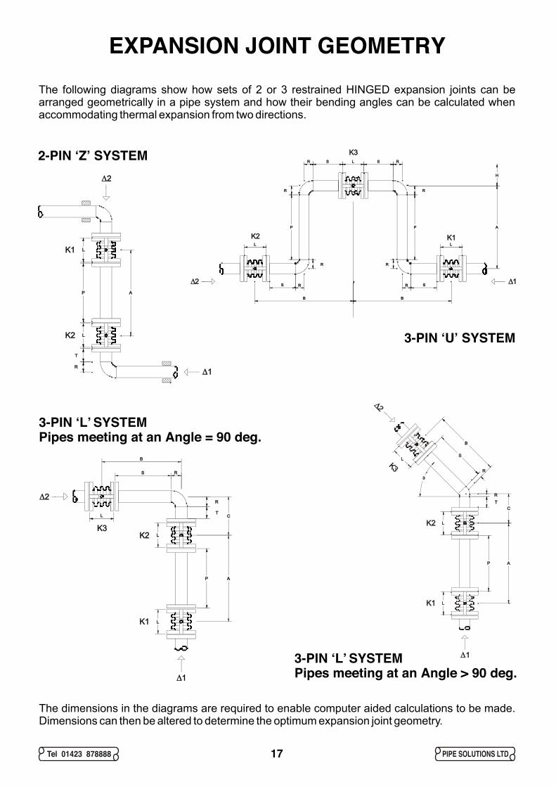
EXPANSION JOINT GEOMETRYThe following diagrams show how sets of 2 or 3 restrained HINGED expansion joints can be arranged geometrically in a pipe system and how their bending angles can be calculated when accommodating thermal expansion from two directions.
The dimensions in the diagrams are required to enable computer aided calculations to be made. Dimensions can then be altered to determine the optimum expansion joint geometry.
2-PIN ‘Z’ SYSTEM
3-PIN ‘U’ SYSTEM
3-PIN ‘L’ SYSTEMPipes meeting at an Angle = 90 deg.
3-PIN ‘L’ SYSTEMPipes meeting at an Angle > 90 deg.
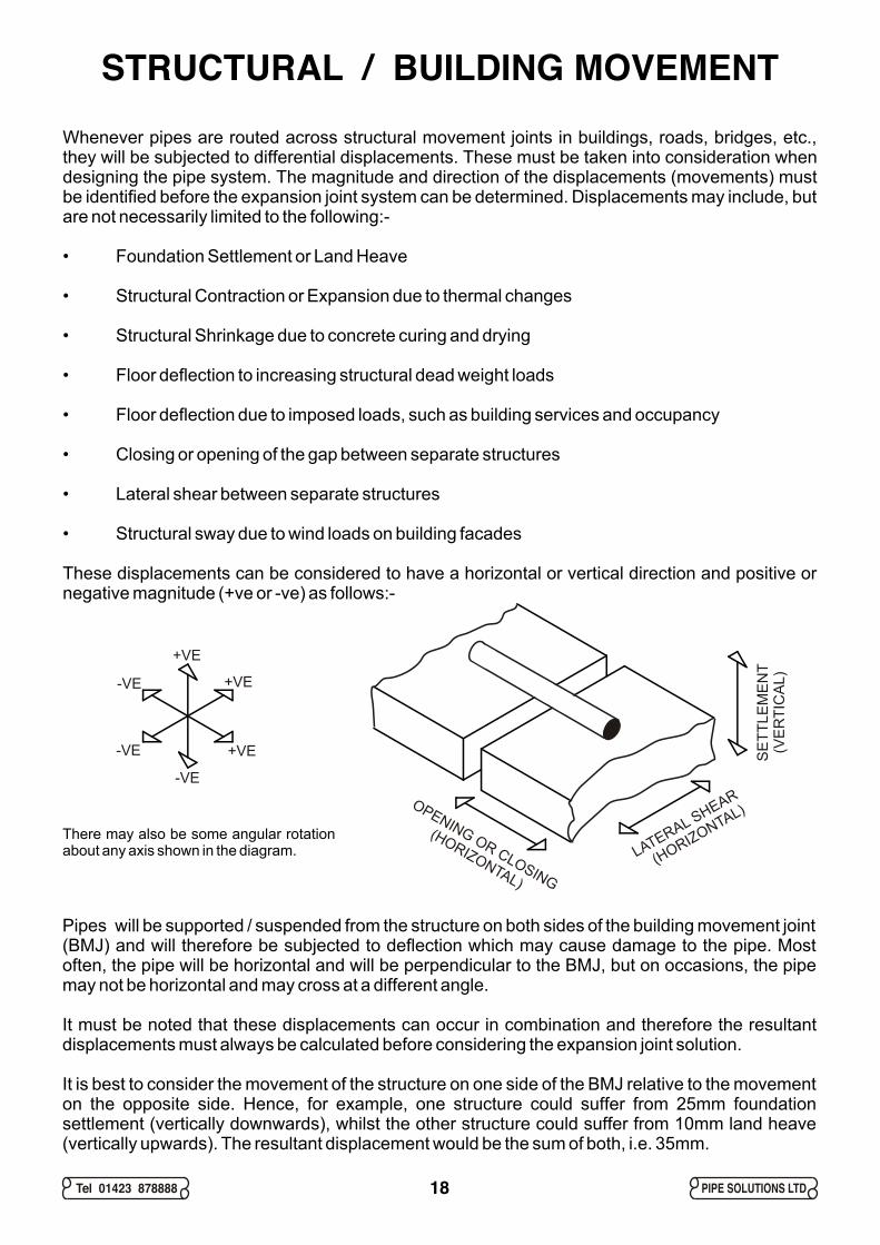
STRUCTURAL / BUILDING MOVEMENTWhenever pipes are routed across structural movement joints in buildings, roads, bridges, etc., they will be subjected to differential displacements. These must be taken into consideration when designing the pipe system. The magnitude and direction of the displacements (movements) must be identified before the expansion joint system can be determined. Displacements may include, but are not necessarily limited to the following:-
• Foundation Settlement or Land Heave
• Structural Contraction or Expansion due to thermal changes
• Structural Shrinkage due to concrete curing and drying
• Floor deflection to increasing structural dead weight loads
• Floor deflection due to imposed loads, such as building services and occupancy
• Closing or opening of the gap between separate structures
• Lateral shear between separate structures
• Structural sway due to wind loads on building facades
These displacements can be considered to have a horizontal or vertical direction and positive or negative magnitude (+ve or -ve) as follows:-
Pipes will be supported / suspended from the structure on both sides of the building movement joint (BMJ) and will therefore be subjected to deflection which may cause damage to the pipe. Most often, the pipe will be horizontal and will be perpendicular to the BMJ, but on occasions, the pipe may not be horizontal and may cross at a different angle.
It must be noted that these displacements can occur in combination and therefore the resultant displacements must always be calculated before considering the expansion joint solution.
It is best to consider the movement of the structure on one side of the BMJ relative to the movement on the opposite side. Hence, for example, one structure could suffer from 25mm foundation settlement (vertically downwards), whilst the other structure could suffer from 10mm land heave (vertically upwards). The resultant displacement would be the sum of both, i.e. 35mm.
+VE
+VE
+VE
-VE
-VE
-VE
Tel 01423 878888 PIPE SOLUTIONS LTD18
There may also be some angular rotation about any axis shown in the diagram.
OPENING OR CLOSING
(HORIZONTAL)
SE
TTLE
ME
NT
(VE
RTI
CA
L)
LATERAL SHEAR
(HORIZONTAL)

Tel 01423 878888 PIPE SOLUTIONS LTD
PIPE ANCHORSPipe anchors are required to control pipe expansion or contraction, and for ‘natural’ flexibility or expansion joints to function as designed. The forces acting on the pipe anchors will comprise one or more of the following:-
• Friction force of the pipe moving over the supports, relative to pipe slope
• Bending force of the offset or branch
• Spring force of the bellows of the expansion joint
• Pressure thrust force of unrestrained expansion joints
• Centrifugal force of the flowing media acting on pipe direction changes
• Wind loading force relative to wind speed and height above ground
• Dead weight force of pipe, media, insulation and components
Each of these forces are considered separately over the next few pages as follows:-
Friction Force
As the pipe expands or contracts over its supports, it encounters friction. The anchors must resist this friction force, which is a function of the weight of the pipe, insulation and contents, coefficient of friction and the slope of the pipe. For vertical pipes (risers), friction forces are small, but can be estimated at 15% of the anchor force multiplied by the coefficient of friction.
The friction force can be calculated mathematically using the formula:- F = M × G × CFriction
Where, F = Force (N)M = Mass (kg)
2G = Gravitational Acceleration (9.81m/s )C = Coefficient of FrictionFriction
Coefficients of friction vary. As a guide, use the following:-
Steel on P.T.F.E. = 0.03Point Contact steel on steel = 0.20Line Contact steel on steel = 0.25Edge Contact steel on steel = 0.30Face to Face Contact steel on steel = 0.40
Friction force (N) for 1m horizontal length of water filled insulated* BS1387 heavy steel pipe15mm 20mm 25mm 32mm 40mm 50mm 65mm 80mm 100mm 125mm 150mm
0.03 0.5 0.6 1.0 1.4 1.7 2.4 3.4 4.4 6.7 9.1 11.70.2 3.1 4.3 6.9 9.4 11.2 16.3 22.6 29.4 44.7 60.6 78.30.25 3.9 5.4 8.6 11.8 14.0 20.4 28.2 36.8 55.9 75.8 97.90.3 4.7 6.5 10.3 14.1 16.8 24.4 33.8 44.1 67.1 90.9 117.40.4 6.3 8.6 13.7 18.8 22.4 32.6 45.1 58.9 89.5 121.3 156.6
Coefficient of Friction
*Insulati on is 50mm thi ck and has a density of 200k g per cub ic metr e
19
Tel 01423 878888 PIPE SOLUTIONS LTD
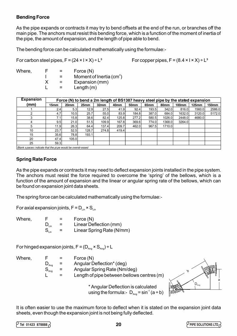
Bending Force
As the pipe expands or contracts it may try to bend offsets at the end of the run, or branches off the main pipe. The anchors must resist this bending force, which is a function of the moment of inertia of the pipe, the amount of expansion, and the length of pipe able to bend.
The bending force can be calculated mathematically using the formulae:- For carbon steel pipes, F = (24 × I × X) ÷ L³ For copper pipes, F = (8.4 × I × X) ÷ L³
Where, F = Force (N)4I = Moment of Inertia (cm )
X = Expansion (mm)L = Length (m)
Spring Rate Force
As the pipe expands or contracts it may need to deflect expansion joints installed in the pipe system. The anchors must resist the force required to overcome the ‘spring’ of the bellows, which is a function of the amount of expansion and the linear or angular spring rate of the bellows, which can be found on expansion joint data sheets.
The spring force can be calculated mathematically using the formulae:- For axial expansion joints, F = D × SLin Lin
Where, F = Force (N)D = Linear Deflection (mm)Lin
S = Linear Spring Rate (N/mm)Lin
For hinged expansion joints, F = (D × S ) ÷ LAng Ang
Where, F = Force (N)D = Angular Deflection* (deg)Ang
S = Angular Spring Rate (Nm/deg)Ang
L = Length of pipe between bellows centres (m)
It is often easier to use the maximum force to deflect when it is stated on the expansion joint data sheets, even though the expansion joint is not being fully deflected.
Force (N) to bend a 2m length of BS1387 heavy steel pipe by the stated expansion15mm 20mm 25mm 32mm 40mm 50mm 65mm 80mm 100mm 125mm 150mm
1 2.4 5.3 12.9 27.5 41.9 92.4 193.5 342.0 816.0 1560.0 2586.02 4.7 10.5 25.7 55.0 83.9 184.8 387.0 684.0 1632.0 3120.0 5172.03 7.1 15.8 38.6 82.4 125.8 277.2 580.5 1026.0 2448.0 4680.04 9.5 21.0 51.5 109.9 167.8 369.6 774.0 1368.0 3264.05 11.9 26.3 64.4 137.4 209.7 462.0 967.5 1710.0
10 23.7 52.5 128.7 274.8 419.415 35.6 78.8 193.120 47.4 105.025 59.3
Expansion (mm)
Blank s paces i ndicate that the pi pe would be overstr essed
20
* Angular Deflection is calculated -1using the formula:- D = sin (a ÷ b) Ang
1 1 DAng
a
b

Tel 01423 878888 PIPE SOLUTIONS LTD
Pressure Thrust Force
As the pipe expands it may need to deflect axial expansion joints installed in the pipe system. The anchors must be able to resist the pressure thrust force which is present whenever unrestrained (axial) expansion joints are used. This force is a function of the effective area of the bellows and the working or test pressure at the expansion joint location.
The pressure thrust force can be calculated mathematically using the formulae:- For working conditions, F = A × P × 0.1 For test conditions, F = A × P × 0.1E working E test
Where, F = Force (N)2A = Effective Area (cm ), taken from data sheetsE
2P = Working Pressure (kN/m )Working2P = Test Pressure (kN/m ), often 1.5x working pressureTest
0.1 = Correction Factor, due to measurement units used
Centrifugal Force
As the media flows through the pipe, it encounters bends. At these bends the flowing media exerts a centrifugal force on the pipe. The anchors (and guides) may have to resist this centrifugal force, which is a function of the media density, media velocity, area of the bend and bend angle.
2The centrifugal force can be calculated mathematically using the formula:- F=(D×V ×A×Sin B )Ang
Where, F = Force (N)3D = Density of the media (kg/m )
V = Velocity (m/s)2A = Area of the bend on which the flowing media acts (m )
B = Bend Angle (degrees)Ang
Pressure Thrust Force (N) exerted by Axial Expansion Joints at the stated pressure(kN/m²) (bar) 15mm 20mm 25mm 32mm 40mm 50mm 65mm 80mm 100mm 125mm 150mm
100 1 60 80 100 190 230 350 530 720 1110 1690 2340200 2 120 160 200 380 460 700 1060 1440 2220 3380 4680300 3 180 240 300 570 690 1050 1590 2160 3330 5070 7020400 4 240 320 400 760 920 1400 2120 2880 4440 6760 9360500 5 300 400 500 950 1150 1750 2650 3600 5550 8450 11700600 6 360 480 600 1140 1380 2100 3180 4320 6660 10140 14040700 7 420 560 700 1330 1610 2450 3710 5040 7770 11830 16380800 8 480 640 800 1520 1840 2800 4240 5760 8880 13520 18720900 9 540 720 900 1710 2070 3150 4770 6480 9990 15210 210601000 10 600 800 1000 1900 2300 3500 5300 7200 11100 16900 234001100 11 660 880 1100 2090 2530 3850 5830 7920 12210 18590 257401200 12 720 960 1200 2280 2760 4200 6360 8640 13320 20280 280801300 13 780 1040 1300 2470 2990 4550 6890 9360 14430 21970 304201400 14 840 1120 1400 2660 3220 4900 7420 10080 15540 23660 327601500 15 900 1200 1500 2850 3450 5250 7950 10800 16650 25350 351001600 16 960 1280 1600 3040 3680 5600 8480 11520 17760 27040 374402000 20 1200 1600 2000 3800 4600 7000 10600 14400 22200 33800 468002400 24 1440 1920 2400 4560 5520 8400 12720 17280 26640 40560 56160
Pressure
15mm 20mm 25mm 32mm 40mm 50mm 65mm 80mm 100mm 125mm 150mm1.0 0.2 0.4 0.6 1.0 1.4 2.2 3.7 5.1 8.7 13.3 19.02.0 0.8 1.5 2.3 4.1 5.5 8.8 14.8 20.5 34.7 53.0 75.83.0 1.8 3.3 5.3 9.1 12.4 19.8 33.3 46.0 78.1 119.3 170.64.0 3.3 5.9 9.4 16.3 22.0 35.3 59.2 81.8 138.9 212.0 303.25.0 5.1 9.2 14.7 25.4 34.4 55.1 92.5 127.9 217.0 331.3 473.86.0 7.4 13.2 21.1 36.6 49.5 79.4 133.2 184.1 312.5 477.0 682.2
Velocity (m/s)
Water dens ity at 20C is 1000kg/m3
Centrifugal force (N) for water flowing round a 90deg steel pipe bend at the stated velocity
21
Tel 01423 878888 PIPE SOLUTIONS LTD
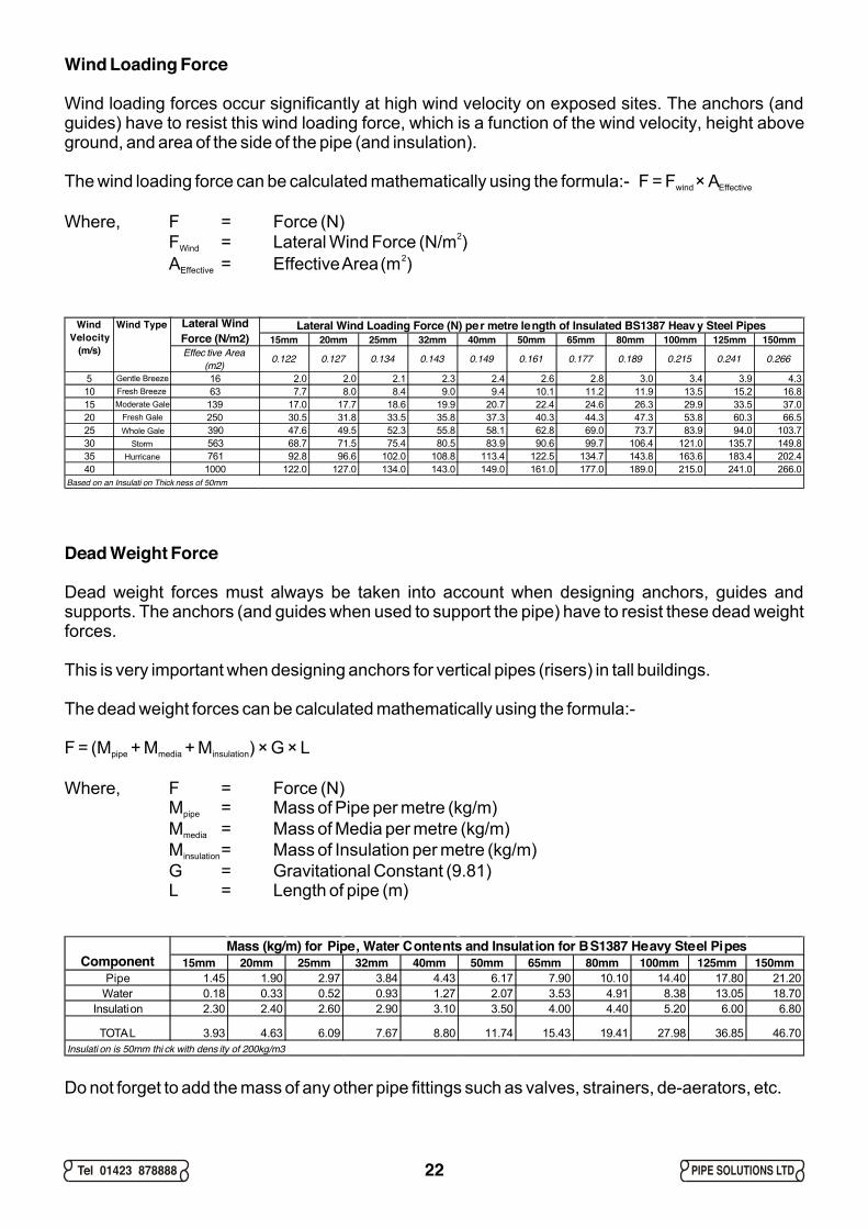
Wind Loading Force
Wind loading forces occur significantly at high wind velocity on exposed sites. The anchors (and guides) have to resist this wind loading force, which is a function of the wind velocity, height above ground, and area of the side of the pipe (and insulation).
The wind loading force can be calculated mathematically using the formula:- F = F × Awind Effective
Where, F = Force (N)2F = Lateral Wind Force (N/m )Wind
2A = Effective Area (m )Effective
Dead Weight Force
Dead weight forces must always be taken into account when designing anchors, guides and supports. The anchors (and guides when used to support the pipe) have to resist these dead weight forces.
This is very important when designing anchors for vertical pipes (risers) in tall buildings.
The dead weight forces can be calculated mathematically using the formula:-
F = (M + M + M ) × G × Lpipe media insulation
Where, F = Force (N)M = Mass of Pipe per metre (kg/m)pipe
M = Mass of Media per metre (kg/m)media
M = Mass of Insulation per metre (kg/m)insulation
G = Gravitational Constant (9.81)L = Length of pipe (m)
Mass (kg/m) for Pipe, Water Contents and Insulat ion for BS1387 Heavy Steel Pipes15mm 20mm 25mm 32mm 40mm 50mm 65mm 80mm 100mm 125mm 150mm
Pipe 1.45 1.90 2.97 3.84 4.43 6.17 7.90 10.10 14.40 17.80 21.20Water 0.18 0.33 0.52 0.93 1.27 2.07 3.53 4.91 8.38 13.05 18.70
Insulation 2.30 2.40 2.60 2.90 3.10 3.50 4.00 4.40 5.20 6.00 6.80
TOTAL 3.93 4.63 6.09 7.67 8.80 11.74 15.43 19.41 27.98 36.85 46.70
Component
Insulati on is 50mm thi ck with dens ity of 200kg/m3
Lateral Wind Loading Force (N) pe r metre length of Insulated BS1387 Heav y Steel Pipes15mm 20mm 25mm 32mm 40mm 50mm 65mm 80mm 100mm 125mm 150mm
Effec tive Area (m2) 0.122 0.127 0.134 0.143 0.149 0.161 0.177 0.189 0.215 0.241 0.266
5 Gentle Breeze 16 2.0 2.0 2.1 2.3 2.4 2.6 2.8 3.0 3.4 3.9 4.310 Fresh Breeze 63 7.7 8.0 8.4 9.0 9.4 10.1 11.2 11.9 13.5 15.2 16.815 Moderate Gale 139 17.0 17.7 18.6 19.9 20.7 22.4 24.6 26.3 29.9 33.5 37.020 Fresh Gale 250 30.5 31.8 33.5 35.8 37.3 40.3 44.3 47.3 53.8 60.3 66.525 Whole Gale 390 47.6 49.5 52.3 55.8 58.1 62.8 69.0 73.7 83.9 94.0 103.730 Storm 563 68.7 71.5 75.4 80.5 83.9 90.6 99.7 106.4 121.0 135.7 149.835 Hurricane 761 92.8 96.6 102.0 108.8 113.4 122.5 134.7 143.8 163.6 183.4 202.440 1000 122.0 127.0 134.0 143.0 149.0 161.0 177.0 189.0 215.0 241.0 266.0
Lateral Wind Force (N/m2)
Wind Velocity
(m/s)
Wind Type
Based on an Insulati on Thick ness of 50mm
Do not forget to add the mass of any other pipe fittings such as valves, strainers, de-aerators, etc.
22
Tel 01423 878888 PIPE SOLUTIONS LTD
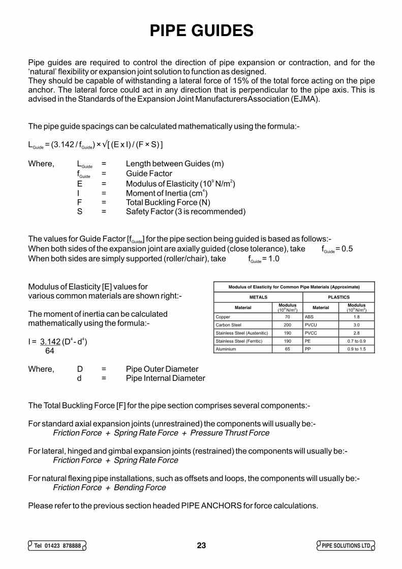
PIPE GUIDESPipe guides are required to control the direction of pipe expansion or contraction, and for the ‘natural’ flexibility or expansion joint solution to function as designed. They should be capable of withstanding a lateral force of 15% of the total force acting on the pipe anchor. The lateral force could act in any direction that is perpendicular to the pipe axis. This is advised in the Standards of the Expansion Joint Manufacturers Association (EJMA).
The pipe guide spacings can be calculated mathematically using the formula:-
L = (3.142 / f ) × [ (E x I) / (F × S) ]Guide Guide
Where, L = Length between Guides (m)Guide
f = Guide Factor Guide9 2E = Modulus of Elasticity (10 N/m )
4I = Moment of Inertia (cm )F = Total Buckling Force (N)S = Safety Factor (3 is recommended)
The values for Guide Factor [f ] for the pipe section being guided is based as follows:-Guide
When both sides of the expansion joint are axially guided (close tolerance), take f = 0.5Guide
When both sides are simply supported (roller/chair), take f = 1.0Guide
Modulus of Elasticity [E] values forvarious common materials are shown right:-
The moment of inertia can be calculatedmathematically using the formula:-
4 4I = 3.142 (D - d ) 64
Where, D = Pipe Outer Diameterd = Pipe Internal Diameter
The Total Buckling Force [F] for the pipe section comprises several components:-
For standard axial expansion joints (unrestrained) the components will usually be:-Friction Force + Spring Rate Force + Pressure Thrust Force
For lateral, hinged and gimbal expansion joints (restrained) the components will usually be:-Friction Force + Spring Rate Force
For natural flexing pipe installations, such as offsets and loops, the components will usually be:-Friction Force + Bending Force
Please refer to the previous section headed PIPE ANCHORS for force calculations.
Ö
23
Modulus of Elasticity for Common Pipe Materials (Approximate)
METALS PLASTICS
Material Modulus (109 N/m2) Material Modulus
(109 N/m2) Copper 70 ABS 1.8
Carbon Steel 200 PVCU 3.0
Stainless Steel (Austenitic) 190 PVCC 2.8
Stainless Steel (Ferritic) 190 PE 0.7 to 0.9
Aluminium 65 PP 0.9 to 1.5
Tel 01423 878888 PIPE SOLUTIONS LTD
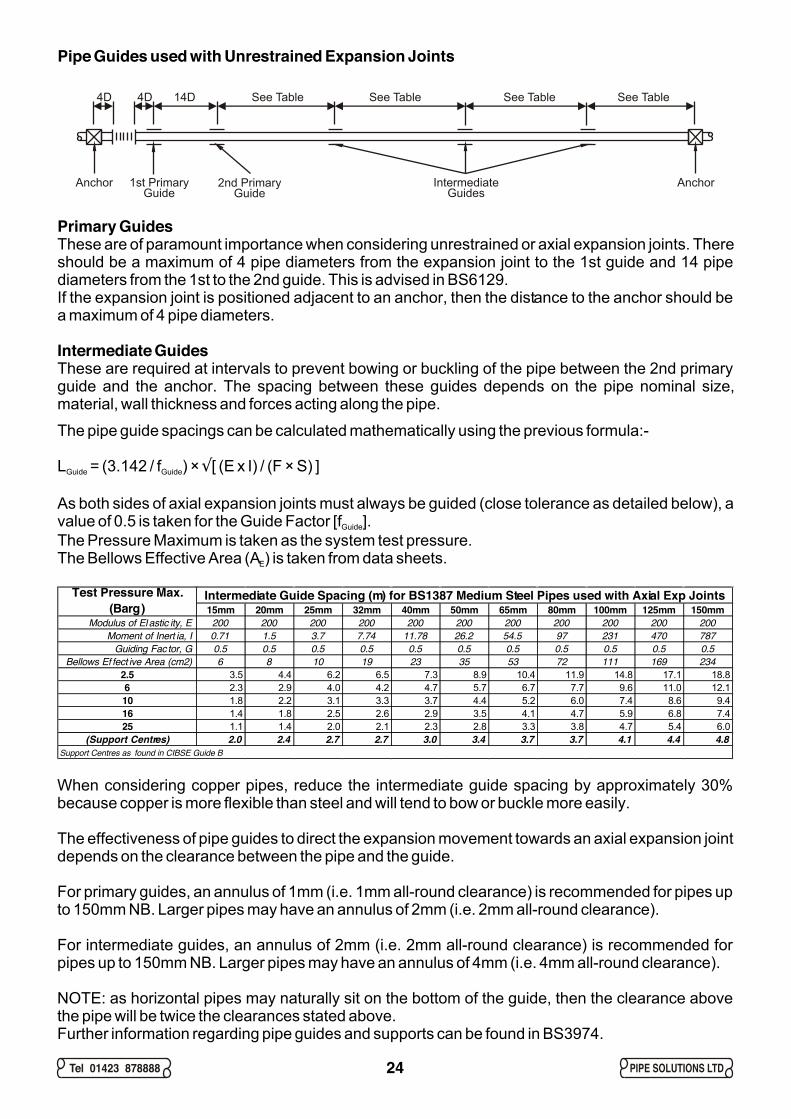
Primary GuidesThese are of paramount importance when considering unrestrained or axial expansion joints. There should be a maximum of 4 pipe diameters from the expansion joint to the 1st guide and 14 pipe diameters from the 1st to the 2nd guide. This is advised in BS6129.If the expansion joint is positioned adjacent to an anchor, then the distance to the anchor should be a maximum of 4 pipe diameters.
Intermediate GuidesThese are required at intervals to prevent bowing or buckling of the pipe between the 2nd primary guide and the anchor. The spacing between these guides depends on the pipe nominal size, material, wall thickness and forces acting along the pipe.
The pipe guide spacings can be calculated mathematically using the previous formula:-
L = (3.142 / f ) × [ (E x I) / (F × S) ]Guide Guide
As both sides of axial expansion joints must always be guided (close tolerance as detailed below), a value of 0.5 is taken for the Guide Factor [f ].Guide
The Pressure Maximum is taken as the system test pressure. The Bellows Effective Area (A ) is taken from data sheets.E
Ö
When considering copper pipes, reduce the intermediate guide spacing by approximately 30% because copper is more flexible than steel and will tend to bow or buckle more easily.
The effectiveness of pipe guides to direct the expansion movement towards an axial expansion joint depends on the clearance between the pipe and the guide.
For primary guides, an annulus of 1mm (i.e. 1mm all-round clearance) is recommended for pipes up to 150mm NB. Larger pipes may have an annulus of 2mm (i.e. 2mm all-round clearance).
For intermediate guides, an annulus of 2mm (i.e. 2mm all-round clearance) is recommended for pipes up to 150mm NB. Larger pipes may have an annulus of 4mm (i.e. 4mm all-round clearance).
NOTE: as horizontal pipes may naturally sit on the bottom of the guide, then the clearance above the pipe will be twice the clearances stated above.Further information regarding pipe guides and supports can be found in BS3974.
Pipe Guides used with Unrestrained Expansion Joints
24
Anchor
4D 4D 14D See Table See Table See Table See Table
Anchor1st PrimaryGuide
2nd PrimaryGuide
IntermediateGuides
Intermediate Guide Spacing (m) for BS1387 Medium Steel Pipes used with Axial Exp Joints15mm 20mm 25mm 32mm 40mm 50mm 65mm 80mm 100mm 125mm 150mm
Modulus of Elastic ity, E 200 200 200 200 200 200 200 200 200 200 200Moment of Inert ia, I 0.71 1.5 3.7 7.74 11.78 26.2 54.5 97 231 470 787
Guiding Fac tor, G 0.5 0.5 0.5 0.5 0.5 0.5 0.5 0.5 0.5 0.5 0.5Bellows Ef fect ive Area (cm2) 6 8 10 19 23 35 53 72 111 169 234
2.5 3.5 4.4 6.2 6.5 7.3 8.9 10.4 11.9 14.8 17.1 18.86 2.3 2.9 4.0 4.2 4.7 5.7 6.7 7.7 9.6 11.0 12.110 1.8 2.2 3.1 3.3 3.7 4.4 5.2 6.0 7.4 8.6 9.416 1.4 1.8 2.5 2.6 2.9 3.5 4.1 4.7 5.9 6.8 7.425 1.1 1.4 2.0 2.1 2.3 2.8 3.3 3.8 4.7 5.4 6.0
(Support Centres) 2.0 2.4 2.7 2.7 3.0 3.4 3.7 3.7 4.1 4.4 4.8
Test Pressure Max. (Barg)
Support Centres as found in CIBSE Guide B
Tel 01423 878888 PIPE SOLUTIONS LTD
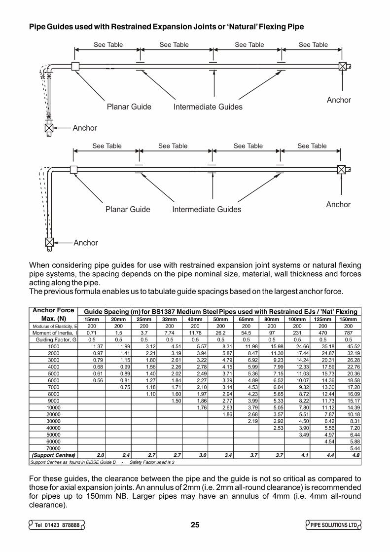
Pipe Guides used with Restrained Expansion Joints or ‘Natural’ Flexing Pipe
When considering pipe guides for use with restrained expansion joint systems or natural flexing pipe systems, the spacing depends on the pipe nominal size, material, wall thickness and forces acting along the pipe.The previous formula enables us to tabulate guide spacings based on the largest anchor force.
For these guides, the clearance between the pipe and the guide is not so critical as compared to those for axial expansion joints. An annulus of 2mm (i.e. 2mm all-round clearance) is recommended for pipes up to 150mm NB. Larger pipes may have an annulus of 4mm (i.e. 4mm all-round clearance).
25
Anchor
AnchorPlanar Guide Intermediate Guides
See Table See Table See Table See Table
Anchor
AnchorPlanar Guide Intermediate Guides
See Table See Table See Table See Table
Guide Spacing (m) for BS1387 Medium Steel Pipes used with Restrained EJs / 'Nat' Flexing15mm 20mm 25mm 32mm 40mm 50mm 65mm 80mm 100mm 125mm 150mm
Modulus of Elasticity, E 200 200 200 200 200 200 200 200 200 200 200Moment of Inertia, I 0.71 1.5 3.7 7.74 11.78 26.2 54.5 97 231 470 787
Guiding Fac tor, G 0.5 0.5 0.5 0.5 0.5 0.5 0.5 0.5 0.5 0.5 0.51000 1.37 1.99 3.12 4.51 5.57 8.31 11.98 15.98 24.66 35.18 45.522000 0.97 1.41 2.21 3.19 3.94 5.87 8.47 11.30 17.44 24.87 32.193000 0.79 1.15 1.80 2.61 3.22 4.79 6.92 9.23 14.24 20.31 26.284000 0.68 0.99 1.56 2.26 2.78 4.15 5.99 7.99 12.33 17.59 22.765000 0.61 0.89 1.40 2.02 2.49 3.71 5.36 7.15 11.03 15.73 20.366000 0.56 0.81 1.27 1.84 2.27 3.39 4.89 6.52 10.07 14.36 18.587000 0.75 1.18 1.71 2.10 3.14 4.53 6.04 9.32 13.30 17.208000 1.10 1.60 1.97 2.94 4.23 5.65 8.72 12.44 16.099000 1.50 1.86 2.77 3.99 5.33 8.22 11.73 15.17
10000 1.76 2.63 3.79 5.05 7.80 11.12 14.3920000 1.86 2.68 3.57 5.51 7.87 10.1830000 2.19 2.92 4.50 6.42 8.3140000 2.53 3.90 5.56 7.2050000 3.49 4.97 6.4460000 4.54 5.8870000 5.44
(Support Centres) 2.0 2.4 2.7 2.7 3.0 3.4 3.7 3.7 4.1 4.4 4.8
Anchor Force Max. (N)
Support Centres as found in CIBSE Guide B - Safety Factor used is 3
Tel 01423 878888 PIPE SOLUTIONS LTD
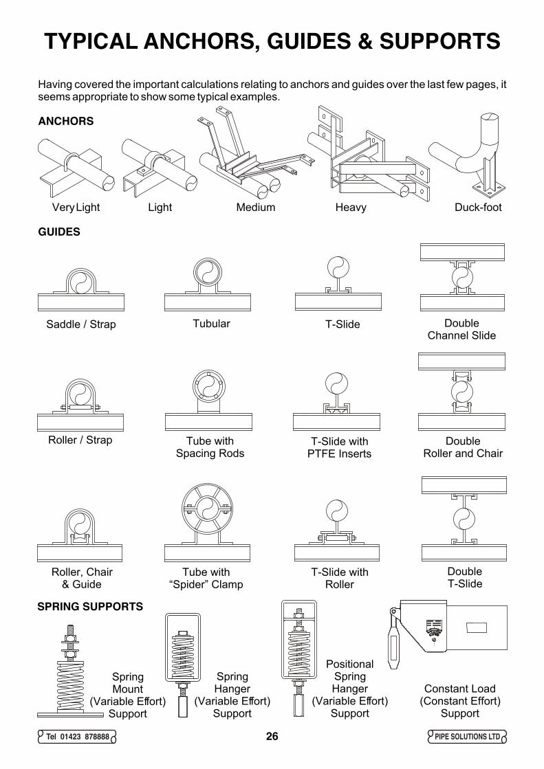
TYPICAL ANCHORS, GUIDES & SUPPORTSHaving covered the important calculations relating to anchors and guides over the last few pages, it seems appropriate to show some typical examples.
ANCHORS
Very Light Light Medium Heavy Duck-foot
GUIDES
SPRING SUPPORTS
26
Saddle / Strap
Roller, Chair & Guide
SpringMount
(Variable Effort)Support
SpringHanger
(Variable Effort)Support
PositionalSpringHanger
(Variable Effort)Support
Constant Load(Constant Effort)
Support
Roller / Strap Tube withSpacing Rods
Tubular
Tube with“Spider” Clamp
T-Slide
T-Slide withPTFE Inserts
T-Slide withRoller
DoubleChannel Slide
DoubleRoller and Chair
DoubleT-Slide
Tel 01423 878888 PIPE SOLUTIONS LTD
COLD PULL (COLD DRAW)Cold pull or cold draw is applicable to the ‘natural’ flexing solution, as well as unrestrained and restrained expansion joint solutions.
Cold pull effectively has the potential to halve the movement being imposed on the pipe offset, loop or expansion joint.
50% Cold Pull
By applying 50% of the expansion in a pipe run as cold pull, a pipe offset or loop is then only required to deflect by a smaller amount, effectively reducing the stresses.
Another way of considering cold pull is that a pipe offset or loop can accommodate more expansion if it is pre-set to position that returns to the neutral position when the pipe is subjected to half the temperature rise, and moves beyond the neutral position when full temperature is reached.
100% Cold Pull
There are occasions when 100% cold pull is best. For example, when considering very high temperature pipes that are subjected to continuous heat (e.g. steam, MTHW or HTHW distribution mains), the working stress in the bellows convolutions can be reduced dramatically if they come to rest in their neutral position.
Pre-Cold Pulled Expansion Joints
Axial expansion joints are often supplied with cold pull applied in the factory. This is good practice as it relieves the engineer on site from applying cold pull on each pipe run. However, where there is a temperature drop after the axial expansion joints have been installed, then models allowing expansion and contraction must be specified.Restrained expansion joints such as the angular and lateral models are not usually supplied pre-cold pulled.
Applying Cold Pull to Unrestrained Expansion Joint Systems
Having calculated the amount of cold pull, a block of timber of thickness equal to the cold pull amount is placed between 2 flanges, either between the axial expansion joint flange and the mating flange, or between 2 mating flanges further down the pipe run before the anchor. The pipe installation, together with anchors and guides is then fully completed. The block of timber can be removed and the gap drawn togther with long high tensile bolts, remembering the gasket of course. The long bolts must not be replaced with standard length bolts and the location must be clearly identified as the COLD PULL position so that future engineers can identify it as such .
Applying Cold Pull to Restrained Expansion Joint Systems and Natural Flexing Pipe
The process is carried out in the same way, with the exception that if there are 2 significant pipe runs with the expansion ‘pushing’ towards the same expansion system, then 2 cold pull positions are recommended.
27
Tel 01423 878888 PIPE SOLUTIONS LTD
OTHER CONSIDERATIONPipe Insulation / LaggingWhen insulating pipes that contain expansion joints, some points should be noted as follows:-
The movement of the expansion joints must not be restricted by the insulation material.The movement of flexing pipe must not be restricted by the insulation material.The insulation material must be removable from the expansion joint to allow for periodic inspection.Care must be taken when considering the type of insulation material to be used, as some materials contain substances that can cause corrosion of the bellows membrane under certain conditions.
Installation Check ListAfter installation of expansion joints, guides, anchors and supports etc, the engineer must consider the following questions:-
Have the correct type of expansion joints been installed ?Have the expansion joints been installed correctly ?Have the expansion joints, guides and anchors been installed in the correct location ?Has the correct amount of cold pull (cold draw) been applied ?Has sufficient clearance been allowed for correct operation of the expansion joints ?Have the expansion joints been damaged in any way ?Have all transport supports been removed ?
CommissioningCommissioning of a pipework system usually includes a pressure test, more often than not at a multiple of 1.5x or 2x the intended system working pressure. The pressure test will normally be at ambient temperature.Removing expansion joints from a system prior to testing is NOT good practice. This defeats the object of testing because other system components, such as anchors, guides, supports, etc are NOT subjected to the larger forces which may be encountered with expansion joints, in particular, axial expansion joints. Also, if expansion joints are not present during the test, any leaks in the expansion joint will not become apparent until the system is under working conditions. The engineer must check points as follows :-
Check BEFORE the pressure test:Ensure that the system test pressure does not exceed the maximum for the expansion joints.Ensure that main and intermediate anchors are strong enough to withstand the test pressure.Ensure that primary and intermediate guides are free to allow pipe movement.Ensure that expansion joint moving parts are free to allow movement.
Check DURING the pressure test: WARNING: Take care when checking pressurised components !Check for any evidence of leakage.Check for any pressure loss.Check for malfunction of expansion joints, anchors, guides and supports.Check in particular for any evidence of snaking or squirm in the bellows membrane.Investigate ALL abnormal changes or unexpected occurance.
Check AFTER the pressure test:Ensure that moving components have returned to their original positions.Ensure that any necessary drain down has been accomplished.
Start Up Check:Ensure that chemical additives are correct and will not damage the expansion joint bellows membrane.Ensure that the thermal expansion of the pipework causes movement in the anticipated manner.Ensure that the expansion joints absorb the movement in the manner for which they were designed.Ensure that all components are still operating within their design limits at maximum system working conditions.Ensure that the system itself is operating within design limits.
Records must be made throughout ALL of the above stages. If problems arise, the procedure MUST be halted and investigated.
Operation and MaintenanceRecords of system changes must be made, such as temperature, pressure, cycling, pipework mod’s etc. Any changes must be evaluated to assess exactly what consequences they may have on system components. Consult the designer of the original system.
Periodic inspection of expansion joints must be made. All expansion joints have a limited life expectancy; this will have been considered during system design, however early failure sometimes occurs due mainly to secondary factors. During periodic inspection the following factors should be looked for:-
Mechanical damage to the bellows convolutions.Corrosion of the bellows convolutions.Loosening of flange bolts or pipe threads.Seizing of guides and supports.Weakening of anchors, guides and supports.Debris or foreign material in the bellows convolutions.Seizing of hinges or ties on expansion joints.
Expansion joints are maintenance free. As part of a maintenance program, expansion joints must be kept clean and free of foreign material. Corrosion protection must be exercised from day one. Soldering flux is HIGHLY CORROSIVE to bellows convolutions.
28
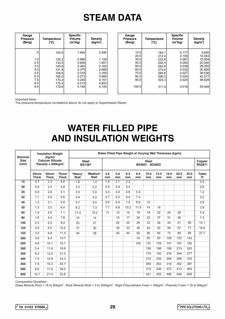
STEAM DATA
WATER FILLED PIPEAND INSULATION WEIGHTS
GaugePressure
(Barg)
0
1.02.03.04.05.06.07.08.09.0
GaugePressure
(Barg)
10.020.030.040.050.060.070.080.090.0
100.0
Temperatureo( C)
100.0
120.2133.5143.6151.8158.8165.0170.4175.4179.9
Temperatureo( C)
184.1212.4233.8250.3263.9275.6285.8295.0303.3
311.0
SpecificVolume
3(m /kg)
1.694
0.8860.6060.4620.3750.3160.2730.2400.2150.194
SpecificVolume
3(m /kg)
0.1770.1000.0670.0500.0390.0320.0270.0240.020
0.018
Density3(kg/m )
0.590
1.1291.6512.1632.6683.1693.6664.1614.6535.144
Density3(kg/m )
5.65010.04315.00420.09225.35530.82636.53642.51748.828
55.494
29Tel 01423 878888 PIPE SOLUTIONS LTD
Water Filled Pipe Weight at Varying Wall Thickness (kg/m)
SteelBS3601 BS3602
SteelBS1387
CopperBS2871
Insulation Weight (kg/m)
Calcium Silicate3*Density = 200kg/m
Nominal Size(mm)
'Heavy'Wall
'Medium'Wall
Table'X'
25mmThick
50mmThick
75mmThick
8.2 7.31.3
4.6
8.6
8.8 3.96.4
16.1
28.0
11.9
30 18.838
7.73.5
10.1
17.9
10.2 14 16
115 147129 167 192
33 43 5850 67 77
260 316283 352 397
4.0mm
5.0mm
6.3mm
8.0mm
10.0mm
12.5mm
16.0mm
20.0mm
25.0mm
1.82.3
4.4
2.415
15012510080655040322520
350300250200
450400
600500
2.2 2.00.8
2.2
2.9 0.84.8
8.9
2.52.4
5.2
3.4
3.5 3.00.9
2.6
6.2
4.0 1.25.1
10.2
21.0
3.42.6
6.0
13.2
4.6
5.7 5.01.2
3.8
7.8
6.5 2.65.8
13.7
25.7
8.8
7.4
5.3
74
56 7564 86 99
310 372336 413 463
22 13.128
5.63.1
8.4
16.3
7.5 10
83 10893 123 142
25 33 4438 51 58
215 264236 296 335
4.8 4.21.1
3.0
7.0
5.5 2.05.6
11.4
23.3
15 7.320
4.72.9
6.8
14.8
6.4
17 23 3127 36
174 216192 244 277
1.6 1.40.7
1.8
2.1 0.44.6
7.8
11.4
15 14
23 21
31 30
40 38
10.21.6
5.4
10.1
12 5.47.1
18.6
32.8
16
40 27.750
114.0
11.6
21.0
14 19 2522 29
150 188166 213 243
44
104
421 496452 546 606
Comparative Densities:- 3 3 3 3 Glass Mineral Wool = 16 to 80kg/m , Rock Mineral Wool = 3 to 200kg/m , Rigid Polyurethane Foam = 50kg/m , Phenolic Foam = 35 to 60kg/m
Important Note:- The pressure-temperature correlations above do not apply to Superheated Steam.
30Tel 01423 878888 PIPE SOLUTIONS LTD
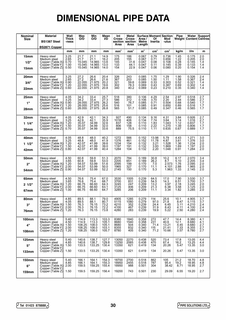
DIMENSIONAL PIPE DATANominal
SizeMaterial
BS1387 Steel
BS2871 Copper
WallThick-ness
MaxO/D
MinO/D
MeanI/D
IntCross-section
Area
MetalCross-section
Area
SurfaceArea /Metre
Length
MomentOf
Inertia
SectionMod-ulus
PipeWeight
WaterContent
SupportCentres
mm mm mm mm 2mm 2mm 2m 4cm 3cm kg/m l/m mHeavy steelMedium steelCopper (Table X)Copper (Table Y)Copper (Table Z)
Heavy steelMedium steelCopper (Table X)Copper (Table Y)Copper (Table Z)
Heavy steelMedium steelCopper (Table X)Copper (Table Y)Copper (Table Z)
Heavy steelMedium steelCopper (Table X)Copper (Table Y)Copper (Table Z)
Heavy steelMedium steelCopper (Table X)Copper (Table Y)Copper (Table Z)
Heavy steelMedium steelCopper (Table X)Copper (Table Y)Copper (Table Z)
Heavy steelMedium steelCopper (Table X)Copper (Table Y)Copper (Table Z)
Heavy steelMedium steelCopper (Table X)Copper (Table Y)Copper (Table Z)
Heavy steelMedium steelCopper (Table X)Copper (Table Y)Copper (Table Z)
Heavy steelMedium steelCopper (Table X)Copper (Table Y)Copper (Table Z)
Heavy steelMedium steelCopper (Table X)Copper (Table Y)Copper (Table Z)
15mm
1/2"
15mm
20mm
3/4"
22mm
25mm
1"
28mm
32mm
1 1/4"
35mm
40mm
1 1/2"
42mm
50mm
2"
54mm
65mm
2 1/2"
67mm
80mm
3"
76mm
100mm
4"
108mm
125mm
5"
133mm
150mm
6"
159mm
3.252.650.701.000.50
3.252.650.901.200.60
4.053.250.901.200.60
4.053.251.201.500.70
4.053.251.201.500.80
4.503.651.202.000.90
4.503.651.202.001.00
4.854.051.502.001.20
5.404.501.502.001.20
5.404.851.50 1.50
5.404.852.00
1.50
21.721.715.04515.04515.045
21.121.114.96514.96514.965
14.916.213.613.014.0
175205145133154
186155 31.6 44.1 22.9
0.0670.0670.0470.0470.047
0.790.710.080.110.06
0.7360.6560.1080.1450.080
1.451.220.280.390.20
0.1750.2050.1450.1330.154
2.02.01.41.41.4
27.227.222.05522.05522.055
26.626.621.97521.97521.975
20.421.620.219.620.8
326367321302340
243203 59.6 78.3 40.2
0.0850.0850.0690.0690.069
1.751.500.330.430.23
1.291.110.3030.3870.210
1.901.580.520.690.35
0.3260.3670.3210.3020.340
2.42.41.41.41.4
34.234.228.05528.05528.055
33.433.427.97527.97527.975
25.727.326.225.626.8
518586540516565
380312 76.7101 51.7
0.1060.1060.0850.0850.085
4.293.700.710.910.49
2.542.200.5040.6500.347
2.972.440.680.890.46
0.5180.5860.5400.5160.565
2.72.71.71.71.7
42.942.935.0735.0735.07
42.142.134.9934.9934.99
34.335.932.632.033.6
9271016 837 806 889
490406128158 75.5
0.1340.1340.1100.1100.110
9.167.741.832.221.11
4.313.641.0431.2700.635
3.843.141.121.390.67
0.9261.0160.8370.8060.889
2.72.71.71.71.7
48.848.842.0742.0742.07
48.048.041.9941.9941.99
40.241.939.639.040.4
12721376123411971284
566461154191104
0.1520.1520.1320.1320.132
13.9811.78 3.21 3.93 2.20
5.794.871.5281.8691.048
4.433.611.361.690.91
1.2711.3761.2341.1971.284
3.03.02.02.02.0
60.860.854.0754.0754.07
59.859.853.9953.9953.99
51.353.051.650.052.2
20702205209519652145
784651199327150
0.1890.1890.1700.1700.170
30.826.2 7.011.1 5.3
10.2 8.7 2.573 4.101 1.963
6.175.101.762.881.33
2.0702.2052.0951.9652.145
3.43.42.02.02.0
76.676.666.7566.7566.75
75.475.466.6066.6066.60
67.068.764.363.164.7
35303700324531253285
1005 831 247 406 206
0.2390.2390.2090.2090.209
64.554.513.221.311.1
17.014.3 3.97 6.38 3.34
7.906.512.183.581.82
3.5303.7003.2453.1253.285
3.73.72.02.02.0
89.589.576.376.376.3
88.188.176.1576.1576.15
79.080.773.272.273.8
49055115421041004280
12851080 352 467 283
0.2790.2790.2390.2390.239
114 97.0 24.4 31.9 19.9
25.621.8 6.45 8.43 5.22
10.1 8.47 3.11 4.11 2.50
4.9055.1154.2104.1004.280
3.73.72.42.42.4
114.9114.9108.25108.25108.25
113.3113.3108.0108.0108.0
103.3105.1105.1103.1105.7
83808680868083558780
18401540 504 832 405
0.3580.3580.3400.3400.340
272231 71.4115 71.2
47.740.613.2121.4110.66
14.412.1 4.45 7.33 3.57
8.3808.6808.6808.3558.780
4.14.12.72.72.7
140.6140.6133.5
133.5
138.7138.7133.25
133.25
127.7129.8130.4
130.4
130501325013350
13350
22702065 621
621
0.4380.4380.419
0.419
520470134
134
73.467.420.26
20.26
17.816.2 5.47
5.47
13.0513.2513.35
13.35
4.44.43.0
3.0
166.1166.1159.5
159.5
164.1164.1159.25
159.25
154.3155.3155.4
156.4
187001895018950
19200
27002455 988
743
0.5180.5180.501
0.501
862787304
230
105 95.4 38.42
29.09
21.219.2 8.71
6.55
18.7018.9518.95
19.20
4.84.82.7
2.7
PIPE SOLUTIONS LIMITED CONDITIONS OF BUSINESS
1. THESE CONDITIONS1.1. These Conditions also apply to the provision of advice or other services by employees of Pipe Solutions Limited1.2. The Buyer acknowledges that these Conditions exclusively define the relationship and agreement with Pipe Solutions Limited and that they supersede all other agreements and Conditions 1.3. No variation in these Conditions, expressed or implied, shall be accepted by the Pipe Solutions Limited unless expressly agreed in writing and signed by a Director of Pipe Solutions Limited and
signed on behalf of the Buyer
2. LIABILITY2.1. These Conditions limit or exclude the liability of Pipe Solutions Limited to avoid the need for Pipe Solutions Limited to increase the level of it's insurance against the risks so limited or excluded, and
thereby to minimise the cost of the Products or Services supplied to the Buyer2.2. If the Buyer nevertheless requires Pipe Solutions Limited to be responsible for risks or liability which is otherwise limited or excluded by these Conditions, then Pipe Solutions Limited will, at it's
option, quote an alternative price for the supply of the Products or Services to reflect the additional cost of obtaining the appropriate additional insurance or other appropriate cover
3. ORDERS3.1. All orders for the Products made by the Buyer shall be confirmed to Pipe Solutions Limited by the Buyer in writing within 24 hours of being received by Pipe Solutions Limited3.2. Upon receipt of the Buyer's written order confirmation by Pipe Solutions Limited, a binding Contract for the purchase of the Products comprised in the order shall be concluded3.3. Any order made by the Buyer is subject to acceptance by Pipe Solutions Limited and a Contract will only be formed when Pipe Solutions Limited has accepted the Buyer's offer to buy3.4. Records held and procedures adopted by Pipe Solutions Limited in relation to orders placed by the Buyer are prima facie evidence that the Buyer has used or ordered the Product indicated
4. CANCELLATION AND RETURNS4.1. The Buyer is not permitted to cancel the Contract, except where previously agreed in writing by a Director of Pipe Solutions Limited4.2. In the event of cancellation by the Buyer, the Buyer will fully indemnify Pipe Solutions Limited against all expenses incurred up to the time of the cancellation
5. DELIVERY5.1. The Buyer will accept delivery of the Products by Pipe Solutions Limited or its agents on the date, or within the time period stipulated by Pipe Solutions Limited5.2. Any time or period for delivery stipulated by Pipe Solutions Limited shall be deemed an estimate only and Pipe Solutions Limited shall not be liable for the costs and consequences of any delay 5.3. Delivery will be made by or on behalf of Pipe Solutions Limited to anywhere within the United Kingdom specified by the Buyer. Delivery to the Buyer's carrier or agent shall be deemed to be delivery
to the Buyer for the purpose of these Conditions5.4. Pipe Solutions Limited shall not be liable for any loss whatsoever or howsoever arising caused by its non-delivery or by failure to make Products available ready for collection on the due date
6. PAYMENT6.1. Unless otherwise agreed in writing, payment for the Products or Services will be made within 30 days from the invoice date6.2. Unless otherwise agreed in writing, no payment discount or allowance will be made6.3. Interest on any overdue account may be charged on a day to day basis at a rate of 6% above the Bank of England base lending rate6.4. Value Added Tax at the ruling shall be added to the price and shall form part of the purchase price of the Products or Services for the purpose of these Conditions6.5. If the Buyer fails to make payment in accordance with these Conditions or other written agreement, Pipe Solutions Limited reserves the right to discontinue, defer or suspend the supply of the
contracted Products or Services to the Buyer, and to refer the Buyer's information to a debt collection or credit reference agency without notice to the Buyer
7. PRICE7.1. The Products or Services will be sold to the Buyer at the prices agreed at the time the order is made by the Buyer7.2. Pipe Solutions Limited reserves the right to increase any fees once each year to reflect changes in the British economy7.3. Any price quoted by Pipe Solutions Limited or contained in any order or contract shall be valid only for 28 days from the date of such quotation, order or contract
8. PROPERTY8.1. The Products shall remain the sole and absolute property of Pipe Solutions Limited and title to and legal and equitable ownership of the Products shall not pass to the Buyer until payment is
received by Pipe Solutions Limited for all monies due from the Buyer8.2. The Buyer acknowledges that until payment for the Products is made in full, the Buyer is in possession of the Products solely as a fiduciary for Pipe Solutions Limited8.3. Without prejudice to any other right or remedies available to it, Pipe Solutions Limited may for the purpose of recovering its Products, and at any time before payment to it of all monies due from the
Buyer, enter upon any premises where such Products are stored, or where they are reasonably thought to be stored, and may repossess the Products
9. PRODUCTS9.1. Where the Products are ordered by reference to any sample, Pipe Solutions Limited shall endeavour to ensure that the Products match the sample9.2. Pipe Solutions Limited warrants that the Products supplied to the Buyer will be suitable for the primary purpose for which the Products are made and normally used9.3. No warranty is given or is implied as to the suitability of the Products for any particular purpose or for use under any specific conditions unless such purpose or conditions have been previously
agreed in writing by Pipe Solutions Limited9.4. Other than in relation to personal injury or death, to the extent permitted by law, Pipe Solutions Limited are not liable to the Buyer or anyone claiming through the Buyer for any loss or damage or
costs sustained or incurred by the Buyer, it's employees, contractors or agents or any third party, arising in any way in connection with this agreement or from the use of, or the supply of the Products9.5. To the extent permitted by law, Pipe Solutions Limited exclude, without limiting the above, liability to the Buyer for consequential loss including, without limitation, loss of profits or business
10. CLAIMS10.1. All claims for loss caused by damage in transit, in storage or on delivery by Pipe Solutions Limited must be notified in writing by the Buyer to Pipe Solutions Limited within three days after receipt of
the Products and must within seven days thereafter be supported by a detailed written claim by the Buyer to Pipe Solutions Limited10.2. All claims for non-delivery, shortages, variances in design, or incorrect specification must be notified to Pipe Solutions Limited by the Buyer in writing no later than three days after the date of
delivery10.3. No claims for shortages, variances in design or incorrect specification shall be accepted in whole or in part by Pipe Solutions Limited if the Products in question have been installed or cut or worked-
upon by the Buyer or its employees or agents10.4. The risk of accidental loss whilst the Products are being returned will be borne by the Buyer
11. OBLIGATIONS11.1. Pipe Solutions Limited shall not be liable or deemed to be in default for any delay or failure to perform its obligations under these Conditions if such delay or failure results directly or indirectly from
any cause beyond the reasonable control of Pipe Solutions Limited.11.2. Delay or failure includes, but is not limited to, acts or restraints of government or governmental agencies, force majeure, act of God, war, riot, civil or criminal disturbance, insurrection, accidents,
fire, explosion, earthquake, flood, the elements, strikes, labour disputes, shortages of suitable material, labour or transport11.3. The obligations of Pipe Solutions Limited may be performed in whole or in part by its authorised distributors, sub-contractors or agents
12. TERMINATION12.1. Pipe Solutions Limited shall be entitled forthwith to terminate any contract incorporating these Conditions and payment thereunder shall immediately become due if the Buyer shall make any
default in, or commit a breach of these Conditions, or of any of its obligations to Pipe Solutions Limited, and have not remedied the same within 10 days of receiving Notice from Pipe Solutions Limited, or if a receiver, provisional liquidator, or administrator or other like person is appointed over any of the Buyer's undertakings or assets or if the Buyer enters into an arrangement with any of it's creditors or becomes insolvent or otherwise is unable to pay it's debts when they fall due
13. ENGLISH LAW13.1. Any contract incorporating these Conditions shall be interpreted in accordance with the English law and shall be enforceable in the English Courts
14. CONTRACT ASSIGNMENT14.1. Any contract incorporating these Conditions may not be assigned by the Buyer without the prior written consent of Pipe Solutions Limited
15. RESERVED RIGHTS15.1. Pipe Solutions Limited reserve the right to obtain credit information from a credit reporting agency and information about the Buyer's commercial activities or commercial credit worthiness from a
business which provides that information, to enable Pipe Solutions Limited to apply a credit policy15.2. Pipe Solutions Limited reserve the right to use any company or organisation that provides invoice discounting or credit factoring services15.3. Pipe Solutions Limited reserve the right to suspend the Buyer's access to Products or Services if there is reasonable cause to do so, or as a result of a direction from any government or other
authority
16. PRODUCT USE 16.1. The Buyer will agree that the Products will be used as designated by Pipe Solutions Limited and in accordance with any current standard or code of practice16.2. Pipe Solutions Limited may advise the Buyer from time to time, but does not carry responsibility for the installation or implementation of the advice given16.3. The Buyer will not, nor will allow others to engage in any activity that is in breach of, or fail to comply with, any applicable law, rule, regulation, standard or code of practice16.4. The Buyer must, at no cost to Pipe Solutions Limited, ensure full, free and safe access to our Products in order for us to inspect the same16.5. The Buyer must provide Pipe Solutions Limited with information that is required in relation to the supply of the Products16.6. The Buyer is solely responsible for the use of the Products and for all payment of fees arising from the use or provision of the Products whether or not the user had the Buyer's authority16.7. Pipe Solutions Limited reserves the right to have any Product fully tested and examined following a reported failure
17. EXEMPTION FROM LIABILITY17.1. In making these Conditions Pipe Solutions Limited does so for itself and for and on behalf of every employee, sub-contractor or agent of Pipe Solutions Limited and the Buyer hereby confirms that
any exemption from liability granted to Pipe Solutions Limited by these Conditions shall also extend to any such employee, sub-contractor or agent of Pipe Solutions Limited
18. NOTICE18.1. Any Notice sent under a contract incorporating these Conditions shall be sent to the registered office of Pipe Solutions Limited or the Buyer (as the case may be) and shall be deemed duly given by
letter 48 hours after being posted by pre-paid registered post or if delivered by hand at the time of delivery
Pipe Solutions Ltd., Head Office, Hornbeam Park Oval, Harrogate, HG2 8RBTel:01423-878888 Fax:01423-878880 Email:[email protected]
Website:www.pipesolutions.co.uk
PIPE SOLUTIONS LTD PROVIDE THE ENGINEER WITH:
Impartial Technical Help
CPD Technical Training Courses
Site Attendance - Surveys and Sign-offs
Technical Reports and Submittals
Prompt Proposals and Quotations
Help with Specification Clauses
Product Data Sheets and Catalogue
Detailed Installation Instructions
Operating & Maintenance Instructions
Web Site for Information Downloads
Quality Management System
TECHNICAL REFERENCE GUIDES COVER:
Vibration and Noise Control
De-aeration and Dirt Removal
Thermal Pipe Expansion
(all publications are also available in PDF format)
12/2010 3
Solutions...brought to you by Hurlstones
Solutions...brought to you by Hurlstones